EP1640243A1 - Rack type electric power steering apparatus - Google Patents
Rack type electric power steering apparatus Download PDFInfo
- Publication number
- EP1640243A1 EP1640243A1 EP04022687A EP04022687A EP1640243A1 EP 1640243 A1 EP1640243 A1 EP 1640243A1 EP 04022687 A EP04022687 A EP 04022687A EP 04022687 A EP04022687 A EP 04022687A EP 1640243 A1 EP1640243 A1 EP 1640243A1
- Authority
- EP
- European Patent Office
- Prior art keywords
- bearing
- rack
- ball nut
- bevel gears
- motor
- Prior art date
- Legal status (The legal status is an assumption and is not a legal conclusion. Google has not performed a legal analysis and makes no representation as to the accuracy of the status listed.)
- Granted
Links
- 229910000831 Steel Inorganic materials 0.000 claims abstract description 5
- 239000010959 steel Substances 0.000 claims abstract description 5
- 230000001154 acute effect Effects 0.000 description 3
- 230000002708 enhancing effect Effects 0.000 description 3
- 238000010276 construction Methods 0.000 description 2
- 238000007796 conventional method Methods 0.000 description 1
- 230000003247 decreasing effect Effects 0.000 description 1
- 230000000694 effects Effects 0.000 description 1
- 238000009434 installation Methods 0.000 description 1
- 239000000463 material Substances 0.000 description 1
- 238000012986 modification Methods 0.000 description 1
- 230000004048 modification Effects 0.000 description 1
Images

Classifications
-
- B—PERFORMING OPERATIONS; TRANSPORTING
- B62—LAND VEHICLES FOR TRAVELLING OTHERWISE THAN ON RAILS
- B62D—MOTOR VEHICLES; TRAILERS
- B62D5/00—Power-assisted or power-driven steering
- B62D5/04—Power-assisted or power-driven steering electrical, e.g. using an electric servo-motor connected to, or forming part of, the steering gear
- B62D5/0421—Electric motor acting on or near steering gear
-
- B—PERFORMING OPERATIONS; TRANSPORTING
- B62—LAND VEHICLES FOR TRAVELLING OTHERWISE THAN ON RAILS
- B62D—MOTOR VEHICLES; TRAILERS
- B62D5/00—Power-assisted or power-driven steering
- B62D5/04—Power-assisted or power-driven steering electrical, e.g. using an electric servo-motor connected to, or forming part of, the steering gear
- B62D5/0442—Conversion of rotational into longitudinal movement
- B62D5/0445—Screw drives
- B62D5/0448—Ball nuts
-
- F—MECHANICAL ENGINEERING; LIGHTING; HEATING; WEAPONS; BLASTING
- F16—ENGINEERING ELEMENTS AND UNITS; GENERAL MEASURES FOR PRODUCING AND MAINTAINING EFFECTIVE FUNCTIONING OF MACHINES OR INSTALLATIONS; THERMAL INSULATION IN GENERAL
- F16H—GEARING
- F16H55/00—Elements with teeth or friction surfaces for conveying motion; Worms, pulleys or sheaves for gearing mechanisms
- F16H55/02—Toothed members; Worms
- F16H55/17—Toothed wheels
- F16H55/18—Special devices for taking up backlash
- F16H55/20—Special devices for taking up backlash for bevel gears
Definitions
- the present invention relates to an electric power steering apparatus, and in particular to a rack type electric power steering apparatus capable of preventing an over tight engagement of bevel gears and an over load of a motor when a bearing supports almost all the axial weight which is applied at a rack bar in such a manner that an axial back lash between a pair of bevel gears generating an assistant force by receiving a driving force of a motor in a rack type electric power steering apparatus is made larger than an axial clearance of the bearing supporting a ball nut.
- a vehicle includes a power steering system for achieving a steering safety.
- a HPS Hydrophilic Power Steering System
- EPS Electronic Power Steering System
- a motor is controlled by an ECU based on a running condition of a vehicle that a vehicle speed sensor and steering torque sensor detect, so that a light and comfort steering feeling is provided when a vehicle runs at a lower speed.
- a vehicle speed sensor and steering torque sensor detect detects a light and comfort steering feeling when a vehicle runs at a lower speed.
- a heavy steering feeling and a stable directivity are achieved.
- a quick steering operation is obtained in an emergency situation, so that an optimum steering condition is provided to a driver.
- the electric power steering apparatus is classified into a column type EPS (C-EPS), a pinion type EPS (E-EPS), and a rack type EPS (R-EPS) based on an installation state.
- C-EPS column type EPS
- E-EPS pinion type EPS
- R-EPS rack type EPS
- R-EPS rack type EPS
- an electric motor installed at an obtuse angle or acute angle at one side of a rack housing is engaged with a gear formed on an outer surface of a ball nut, and the ball nut is rotated by a driving force of the electric motor, so that a rack bar is slid in left and right directions for thereby generating an assistant force based on the operation of a steering wheel.
- FIG. 1 is a schematic cross sectional view illustrating the whole construction of a conventional rack type electric power steering apparatus (R-EPS).
- R-EPS rack type electric power steering apparatus
- a rack bar 2 having a rack gear at one side of an outer surface is installed in a rack housing 1.
- the both ends of the rack bar 2 are ball-jointed with a tie load 3 for thereby transmitting a transfer force of the rack bar 2.
- a pinion 4 is installed at one side of the rack housing 1 at a certain inclination angle with respect to a centerline of the rack bar 2 and is engaged with a rack gear formed at one side of the rack bar 2 for thereby converting a rotational force transferred from a steering shaft into a horizontal movement.
- a motor 5 is installed at the other side of the rack housing 1 at an acute angle or obtuse angle with respect to a centerline of the rack bar 2.
- a bevel gear 50a is engaged at an end of a shaft of the motor 5 and is engaged with a bevel gear 60a of the ball nut 6 supporting the other side of the rack bar 2 in the rack housing 1 for thereby forming a gearing.
- the ball nut 6 is installed in the interior of the rack housing and is rotated by the bearing 7.
- the other side of the rack bar 2 having a ball screw 22 at an inner side of the ball nut 6 slides by a steel ball 8.
- the bevel gears 50a and 60a since the back lash based on the engagement between the bevel gears 50a and 60a is smaller than an axial clearance which is maximum value of amount of movement when an inner race (or an outer race) of the bearing 7 is fixed and an outer race (or an inner race) of the bearing 7 is moved, the bevel gears support almost all the axial weight based on a sliding of the rack bar. Therefore, when the axial weight is applied based on the rack bar, the engaged portions of the bevel gears could be moved in left and right directions, so that a tight engagement occurs. Therefore, an over load occurs in the motor.
- the bevel gears formed of a plastic material could be broken by the above over tight engagement, so that the reliability of the product could be decreased.
- a rack type electric power steering apparatus comprising a pinion connected with a steering wheel; a rack bar that is installed in a rack housing and has one end having a rack gear engaged with the pinion and the other end having a ball screw; a ball nut that is installed at the ball screw in cooperation with a plurality of steel balls; a bearing that rotatably supports the ball nut; a motor that is installed at a certain inclination angle or at a right angle with respect to a center axis of the rack bar; a gearing formed of a pair of bevel gears for transferring a driving force from the motor to the ball nut, wherein a back lash between the bevel gears forming the gearing is larger than an axial clearance of the bearing.
- the bearing is an axial support bearing.
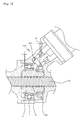
- FIG. 2 is an enlarged view illustrating a ball nut part of a rack type electric power steering apparatus according to the present invention.
- a ball nut 6 surrounding a screw 22 of the other side of a rack bar 2 is inserted and rotatable by a ball bearing 7 which is installed in an inner diameter portion of a rack housing 1.
- a plurality of steel balls 8 are inserted between the ball nut 6 and the screw 22 of the rack bar 2 for thereby guiding the left and right sliding movements of the rack bar 2 and supporting one side of the rack bar.
- a bevel gear 60a is installed around an outer surface of the ball nut, and a motor 5 having a bevel gear 50a engaged with the bevel gear 60a at an end portion of axis of the motor 5 is installed at an obtuse angle or an acute angle with respect to the rack bar 2.
- the back lash B between the engaged bevel gears 50a and 60a is larger than an axial gap, namely, an axial clearance C of the bearing that rotatably supports the ball nut.
- the transferring force of the rack bar 2 is doubled in the direction that the wheels are rotated in combination of the numeral values such as a rotational force transferred to the pinion 4, the speed of the vehicle, the steering angle of the steering wheel, and the rotational torque, so that an optimum steering condition is provided to a driver.
- the bearing 7 and the bevel gear 60a are installed in one side and the other side of the outer surface of the ball nut 6 respectively, the inputted axial weight is supported by the bearing 7 or the bevel gear 60a.
- the back lash based on an engagement of a pair of the bevel gears 50a and 60a forming the gearing 100 is smaller than the inner gap of the axial direction, namely, the axial clearance of the bearing 7, the axial movement distance between the engaged bevel gears is smaller than the axial movement distance of the bearing. Therefore, almost the inputted axial weight is supported by the surface contact between the teeth of the bevel gears. Therefore, an over tight engagement occurs between the teeth of the gears, so that an over load could be applied to the motor.
- the bearing 7 since the back lash B between the bevel gears 50a and 60a is larger than the axial clearance C of the bearing 7, even when the ball nut 6 gets movable in the left or right direction a little by the axial weight, the bearing 7 is getting to support almost all the movement weight. Therefore, it is possible to prevent an over tight engagement due to the engagement of the bevel gears and an over load of the motor. Therefore, in the present invention, it is possible to prevent a damage of the bevel gears for thereby enhancing a reliability of the product.
- the axial bearing configured to support the ball nut could be formed of a four-point bearing, a self-aligning ball bearing, an angular contact bearing, etc., so that the run out of the bevel bearing due to the weights of the axial direction and radial direction of the bearing can be compensated for thereby achieving a smooth operation of the apparatus.
- the axial back lash between the bevel gears is made larger than the axial clearance of the bearing. Therefore, when the axial weight of the rack bar is inputted, the bearing is getting to support almost the weight.
Landscapes
- Engineering & Computer Science (AREA)
- Chemical & Material Sciences (AREA)
- Combustion & Propulsion (AREA)
- Transportation (AREA)
- Mechanical Engineering (AREA)
- Power Steering Mechanism (AREA)
Abstract
Description
- The present invention relates to an electric power steering apparatus, and in particular to a rack type electric power steering apparatus capable of preventing an over tight engagement of bevel gears and an over load of a motor when a bearing supports almost all the axial weight which is applied at a rack bar in such a manner that an axial back lash between a pair of bevel gears generating an assistant force by receiving a driving force of a motor in a rack type electric power steering apparatus is made larger than an axial clearance of the bearing supporting a ball nut.
- Generally, a vehicle includes a power steering system for achieving a steering safety. In the power steering apparatus, a HPS (Hydraulic Power Steering System) has been widely used in a vehicle wherein the HPS adapts a hydraulic pressure. The use of an environment friendly EPS (Electrical Power Steering System) capable of easily achieving an easier steering operation of a driver using a rotational force of a motor increases differently from a conventional method using a hydraulic pressure.
- In the electric power steering apparatus, a motor is controlled by an ECU based on a running condition of a vehicle that a vehicle speed sensor and steering torque sensor detect, so that a light and comfort steering feeling is provided when a vehicle runs at a lower speed. When a vehicle runs at a high speed, a heavy steering feeling and a stable directivity are achieved. A quick steering operation is obtained in an emergency situation, so that an optimum steering condition is provided to a driver.
- The electric power steering apparatus is classified into a column type EPS (C-EPS), a pinion type EPS (E-EPS), and a rack type EPS (R-EPS) based on an installation state.
- Here, in the rack type EPS (R-EPS) in the electric power steering apparatus, an electric motor installed at an obtuse angle or acute angle at one side of a rack housing is engaged with a gear formed on an outer surface of a ball nut, and the ball nut is rotated by a driving force of the electric motor, so that a rack bar is slid in left and right directions for thereby generating an assistant force based on the operation of a steering wheel.
- Figure 1 is a schematic cross sectional view illustrating the whole construction of a conventional rack type electric power steering apparatus (R-EPS). As shown therein, in the rack type electric power steering apparatus, a
rack bar 2 having a rack gear at one side of an outer surface is installed in arack housing 1. The both ends of therack bar 2 are ball-jointed with atie load 3 for thereby transmitting a transfer force of therack bar 2. A pinion 4 is installed at one side of therack housing 1 at a certain inclination angle with respect to a centerline of therack bar 2 and is engaged with a rack gear formed at one side of therack bar 2 for thereby converting a rotational force transferred from a steering shaft into a horizontal movement. - A motor 5 is installed at the other side of the
rack housing 1 at an acute angle or obtuse angle with respect to a centerline of therack bar 2. Abevel gear 50a is engaged at an end of a shaft of the motor 5 and is engaged with abevel gear 60a of the ball nut 6 supporting the other side of therack bar 2 in therack housing 1 for thereby forming a gearing. - In addition, the ball nut 6 is installed in the interior of the rack housing and is rotated by the bearing 7. The other side of the
rack bar 2 having aball screw 22 at an inner side of the ball nut 6 slides by a steel ball 8. - However, in the conventional rack type electric power steering apparatus, since the back lash based on the engagement between the
bevel gears
Therefore, when the axial weight is applied based on the rack bar, the engaged portions of the bevel gears could be moved in left and right directions, so that a tight engagement occurs. Therefore, an over load occurs in the motor. The bevel gears formed of a plastic material could be broken by the above over tight engagement, so that the reliability of the product could be decreased. - Accordingly, it is an object of the present invention to overcome the problems encountered in the conventional art.
- It is an object of the present invention to provide a rack type electric power steering apparatus capable of preventing a possible damage of a bevel gear due to an over tight engagement and enhancing the reliability of a product by preventing an over tight engagement of bevel gears and an over load of a motor when a bearing supports almost all the axial weight which is applied at a rack bar in such a manner that an axial back lash between a pair of bevel gears generating an assistant force by receiving a driving force of a motor in a rack type electric power steering apparatus is made larger than an axial clearance of a bearing supporting a ball nut.
- To achieve the above objects, there is provided a rack type electric power steering apparatus, comprising a pinion connected with a steering wheel; a rack bar that is installed in a rack housing and has one end having a rack gear engaged with the pinion and the other end having a ball screw; a ball nut that is installed at the ball screw in cooperation with a plurality of steel balls; a bearing that rotatably supports the ball nut; a motor that is installed at a certain inclination angle or at a right angle with respect to a center axis of the rack bar; a gearing formed of a pair of bevel gears for transferring a driving force from the motor to the ball nut, wherein a back lash between the bevel gears forming the gearing is larger than an axial clearance of the bearing.
- In the present invention, the bearing is an axial support bearing.
- The present invention will become better understood with reference to the accompanying drawings which are given only by way of illustration and thus are not limitative of the present invention, wherein;
- Figure 1 is a schematic view illustrating a conventional electric power steering apparatus; and
- Figure 2 is a cross sectional enlarged view illustrating a ball nut part of a rack type electric power steering apparatus according to the present invention.
- The preferred embodiments of the present invention will be described with reference to the accompanying drawings.
- The same elements as the construction of the conventional art will be given the same element names and numerals.
- Figure 2 is an enlarged view illustrating a ball nut part of a rack type electric power steering apparatus according to the present invention. As shown therein, a ball nut 6 surrounding a
screw 22 of the other side of arack bar 2 is inserted and rotatable by a ball bearing 7 which is installed in an inner diameter portion of arack housing 1. A plurality of steel balls 8 are inserted between the ball nut 6 and thescrew 22 of therack bar 2 for thereby guiding the left and right sliding movements of therack bar 2 and supporting one side of the rack bar. - In addition, a
bevel gear 60a is installed around an outer surface of the ball nut, and a motor 5 having abevel gear 50a engaged with thebevel gear 60a at an end portion of axis of the motor 5 is installed at an obtuse angle or an acute angle with respect to therack bar 2. - In the present invention, the back lash B between the engaged
bevel gears - The operation and effects of the present invention will be described.
- When a driver rotates a steering wheel (not shown), the transferring force of the
rack bar 2 is doubled in the direction that the wheels are rotated in combination of the numeral values such as a rotational force transferred to the pinion 4, the speed of the vehicle, the steering angle of the steering wheel, and the rotational torque, so that an optimum steering condition is provided to a driver. - In particular, in the rack bar electric power steering apparatus according to the present invention, as shown in Figure 2, when the
rack bar 2 installed in therack housing 1 is slid in left and right directions, an axial back lash B between a pair ofbevel gears rack bar 2, namely, when the weight based on the movement in left and right directions due to the sliding of therack bar 2 is inputted, the bearing 7 can support almost all weight. - As the
rack bar 2 slides in the left and right directions, when the ball nut 7 that supporting therack bar 2 receives the axial weight in the same direction, the bearing 7 and thebevel gear 60a are installed in one side and the other side of the outer surface of the ball nut 6 respectively, the inputted axial weight is supported by the bearing 7 or thebevel gear 60a. In the case that the back lash based on an engagement of a pair of thebevel gears gearing 100 is smaller than the inner gap of the axial direction, namely, the axial clearance of the bearing 7, the axial movement distance between the engaged bevel gears is smaller than the axial movement distance of the bearing. Therefore, almost the inputted axial weight is supported by the surface contact between the teeth of the bevel gears. Therefore, an over tight engagement occurs between the teeth of the gears, so that an over load could be applied to the motor. - On the contrary, in the present invention, since the back lash B between the
bevel gears - The axial bearing configured to support the ball nut could be formed of a four-point bearing, a self-aligning ball bearing, an angular contact bearing, etc., so that the run out of the bevel bearing due to the weights of the axial direction and radial direction of the bearing can be compensated for thereby achieving a smooth operation of the apparatus.
- As described above, in the rack type electric power steering according to the present invention, the axial back lash between the bevel gears is made larger than the axial clearance of the bearing. Therefore, when the axial weight of the rack bar is inputted, the bearing is getting to support almost the weight. In the present invention, it is possible to prevent an over tight engagement due to the engagement of the bevel gears and an over load of the motor. It is possible to prevent a possible damage of the bevel gears that could occur due to the over tight engagement for thereby enhancing a reliability of the product.
- As the present invention may be embodied in several forms without departing from the spirit or essential characteristics thereof, it should also be understood that the above-described examples are not limited by any of the details of the foregoing description, unless otherwise specified, but rather should be construed broadly within its spirit and scope as defined in the appended claims, and therefore all changes and modifications that fall within the meets and bounds of the claims, or equivalences of such meets and bounds are therefore intended to be embraced by the appended claims.
Claims (5)
- A rack type electric power steering apparatus, comprising:a pinion connected with a steering wheel;a rack bar that is installed in a rack housing and has one end having a rack gear engaged with the pinion and the other end having a ball screw;a ball nut that is installed at the ball screw in cooperation with a plurality of steel balls;a bearing that rotatably supports the ball nut;a motor that is installed at a certain inclination angle or at a right angle with respect to a center axis of the rack bar;a gearing formed of a pair of bevel gears for transferring a driving force from the motor to the ball nut, wherein a back lash between the bevel gears forming the gearing is larger than an axial clearance of the bearing.
- The apparatus of claim 1, wherein said bearing is an axial support bearing.
- The apparatus of claim 2, wherein said axial support bearing is a 4-point bearing.
- The apparatus of claim 2, wherein said axial support bearing is a self-aligning bearing.
- The apparatus of claim 2, wherein said axial support bearing is an angular contact bearing.
Priority Applications (2)
| Application Number | Priority Date | Filing Date | Title |
|---|---|---|---|
| EP20040022687 EP1640243B1 (en) | 2004-09-23 | 2004-09-23 | Rack type electric power steering apparatus |
| DE200460011516 DE602004011516T2 (en) | 2004-09-23 | 2004-09-23 | Electrically assisted rack and pinion steering |
Applications Claiming Priority (1)
| Application Number | Priority Date | Filing Date | Title |
|---|---|---|---|
| EP20040022687 EP1640243B1 (en) | 2004-09-23 | 2004-09-23 | Rack type electric power steering apparatus |
Publications (2)
| Publication Number | Publication Date |
|---|---|
| EP1640243A1 true EP1640243A1 (en) | 2006-03-29 |
| EP1640243B1 EP1640243B1 (en) | 2008-01-23 |
Family
ID=34926682
Family Applications (1)
| Application Number | Title | Priority Date | Filing Date |
|---|---|---|---|
| EP20040022687 Expired - Lifetime EP1640243B1 (en) | 2004-09-23 | 2004-09-23 | Rack type electric power steering apparatus |
Country Status (2)
| Country | Link |
|---|---|
| EP (1) | EP1640243B1 (en) |
| DE (1) | DE602004011516T2 (en) |
Cited By (1)
| Publication number | Priority date | Publication date | Assignee | Title |
|---|---|---|---|---|
| CN107031706A (en) * | 2015-10-05 | 2017-08-11 | 株式会社万都 | Rack Assisted Electric Steering |
Citations (3)
| Publication number | Priority date | Publication date | Assignee | Title |
|---|---|---|---|---|
| EP1016581A2 (en) * | 1998-12-28 | 2000-07-05 | Trw Inc. | Electric power steering assembly |
| DE10016197A1 (en) * | 1999-04-01 | 2000-10-05 | Showa Corp Saitama | Electrical servo steering device for moving in compliance with steering force includes a rack-and-pinion mechanism, a ball-and-nut spindle mechanism and an electric motor. |
| JP2002274397A (en) * | 2001-03-22 | 2002-09-25 | Koyo Seiko Co Ltd | Electric power steering device |
-
2004
- 2004-09-23 EP EP20040022687 patent/EP1640243B1/en not_active Expired - Lifetime
- 2004-09-23 DE DE200460011516 patent/DE602004011516T2/en not_active Expired - Lifetime
Patent Citations (3)
| Publication number | Priority date | Publication date | Assignee | Title |
|---|---|---|---|---|
| EP1016581A2 (en) * | 1998-12-28 | 2000-07-05 | Trw Inc. | Electric power steering assembly |
| DE10016197A1 (en) * | 1999-04-01 | 2000-10-05 | Showa Corp Saitama | Electrical servo steering device for moving in compliance with steering force includes a rack-and-pinion mechanism, a ball-and-nut spindle mechanism and an electric motor. |
| JP2002274397A (en) * | 2001-03-22 | 2002-09-25 | Koyo Seiko Co Ltd | Electric power steering device |
Non-Patent Citations (1)
| Title |
|---|
| PATENT ABSTRACTS OF JAPAN vol. 2003, no. 01 14 January 2003 (2003-01-14) * |
Cited By (2)
| Publication number | Priority date | Publication date | Assignee | Title |
|---|---|---|---|---|
| CN107031706A (en) * | 2015-10-05 | 2017-08-11 | 株式会社万都 | Rack Assisted Electric Steering |
| CN107031706B (en) * | 2015-10-05 | 2019-03-15 | 株式会社万都 | Rack-assist electric power steering apparatus |
Also Published As
| Publication number | Publication date |
|---|---|
| DE602004011516D1 (en) | 2008-03-13 |
| DE602004011516T2 (en) | 2009-02-05 |
| EP1640243B1 (en) | 2008-01-23 |
Similar Documents
| Publication | Publication Date | Title |
|---|---|---|
| US8327971B2 (en) | Reducer of electric power steering apparatus | |
| US8001866B2 (en) | Electronic power steering apparatus | |
| US8636099B2 (en) | Rack-driven steering apparatus and rack-driven auxiliary power steering apparatus including the same | |
| US20090260468A1 (en) | Steering device and movement converting device used therefor | |
| KR100621347B1 (en) | Electric power assist steering in cars | |
| US9114823B2 (en) | Actuating device employed in steering system for vehicle | |
| KR100646406B1 (en) | Electric power assist steering in motor vehicle with belt transmission | |
| KR100647116B1 (en) | Steering device of a vehicle | |
| US20060060413A1 (en) | Rack type power steering apparatus | |
| EP1640243B1 (en) | Rack type electric power steering apparatus | |
| US12005971B2 (en) | Rack assist type power steering apparatus | |
| KR100764205B1 (en) | Rack Type Electric Power Steering | |
| KR101172122B1 (en) | Variable Gear Ratio Epicyclic Gear Apparatus | |
| JP2003097661A (en) | Ball screw and wheel steering system using it | |
| JP4114560B2 (en) | Electric power steering device | |
| KR100651157B1 (en) | Gear ratio converter and active front wheel steering device | |
| KR100738430B1 (en) | Electric power steering | |
| KR20040068650A (en) | Free Apartness Absorbing Structure of Worm Shaft for Electric Power Steering System | |
| KR100804570B1 (en) | Electric steering apparatus equipped with planetary gear unit as reducer | |
| KR20060101622A (en) | Reduction Gear Compensation Structure of Electric Power Steering System | |
| KR20110046797A (en) | Reduction gears in electric power assisted steering | |
| KR20070075110A (en) | Variable gear ratio steering with clearance compensation | |
| JP2010038217A (en) | Ball screw device | |
| JP2014098470A (en) | Transmission ratio variable device | |
| KR20040087372A (en) | An Electric Type Power Steering system |
Legal Events
| Date | Code | Title | Description |
|---|---|---|---|
| PUAI | Public reference made under article 153(3) epc to a published international application that has entered the european phase |
Free format text: ORIGINAL CODE: 0009012 |
|
| AK | Designated contracting states |
Kind code of ref document: A1 Designated state(s): AT BE BG CH CY CZ DE DK EE ES FI FR GB GR HU IE IT LI LU MC NL PL PT RO SE SI SK TR |
|
| AX | Request for extension of the european patent |
Extension state: AL HR LT LV MK |
|
| 17P | Request for examination filed |
Effective date: 20060830 |
|
| AKX | Designation fees paid |
Designated state(s): DE FR GB IT |
|
| 17Q | First examination report despatched |
Effective date: 20061207 |
|
| GRAP | Despatch of communication of intention to grant a patent |
Free format text: ORIGINAL CODE: EPIDOSNIGR1 |
|
| GRAS | Grant fee paid |
Free format text: ORIGINAL CODE: EPIDOSNIGR3 |
|
| GRAA | (expected) grant |
Free format text: ORIGINAL CODE: 0009210 |
|
| AK | Designated contracting states |
Kind code of ref document: B1 Designated state(s): DE FR GB IT |
|
| REG | Reference to a national code |
Ref country code: GB Ref legal event code: FG4D |
|
| REF | Corresponds to: |
Ref document number: 602004011516 Country of ref document: DE Date of ref document: 20080313 Kind code of ref document: P |
|
| ET | Fr: translation filed | ||
| PLBE | No opposition filed within time limit |
Free format text: ORIGINAL CODE: 0009261 |
|
| STAA | Information on the status of an ep patent application or granted ep patent |
Free format text: STATUS: NO OPPOSITION FILED WITHIN TIME LIMIT |
|
| 26N | No opposition filed |
Effective date: 20081024 |
|
| REG | Reference to a national code |
Ref country code: FR Ref legal event code: PLFP Year of fee payment: 12 |
|
| PGFP | Annual fee paid to national office [announced via postgrant information from national office to epo] |
Ref country code: IT Payment date: 20150521 Year of fee payment: 12 Ref country code: FR Payment date: 20150521 Year of fee payment: 12 |
|
| PGFP | Annual fee paid to national office [announced via postgrant information from national office to epo] |
Ref country code: GB Payment date: 20150714 Year of fee payment: 12 Ref country code: DE Payment date: 20150521 Year of fee payment: 12 |
|
| REG | Reference to a national code |
Ref country code: DE Ref legal event code: R119 Ref document number: 602004011516 Country of ref document: DE |
|
| GBPC | Gb: european patent ceased through non-payment of renewal fee |
Effective date: 20160923 |
|
| REG | Reference to a national code |
Ref country code: FR Ref legal event code: ST Effective date: 20170531 |
|
| PG25 | Lapsed in a contracting state [announced via postgrant information from national office to epo] |
Ref country code: FR Free format text: LAPSE BECAUSE OF NON-PAYMENT OF DUE FEES Effective date: 20160930 Ref country code: GB Free format text: LAPSE BECAUSE OF NON-PAYMENT OF DUE FEES Effective date: 20160923 Ref country code: DE Free format text: LAPSE BECAUSE OF NON-PAYMENT OF DUE FEES Effective date: 20170401 |
|
| PG25 | Lapsed in a contracting state [announced via postgrant information from national office to epo] |
Ref country code: IT Free format text: LAPSE BECAUSE OF NON-PAYMENT OF DUE FEES Effective date: 20160923 |