EP1640214A1 - Horn switch gear, airbag system comprising this Horn switch gear, and steering device comprising this horn switch gear - Google Patents
Horn switch gear, airbag system comprising this Horn switch gear, and steering device comprising this horn switch gear Download PDFInfo
- Publication number
- EP1640214A1 EP1640214A1 EP05018083A EP05018083A EP1640214A1 EP 1640214 A1 EP1640214 A1 EP 1640214A1 EP 05018083 A EP05018083 A EP 05018083A EP 05018083 A EP05018083 A EP 05018083A EP 1640214 A1 EP1640214 A1 EP 1640214A1
- Authority
- EP
- European Patent Office
- Prior art keywords
- horn
- depression
- plates
- horn switch
- steering
- Prior art date
- Legal status (The legal status is an assumption and is not a legal conclusion. Google has not performed a legal analysis and makes no representation as to the accuracy of the status listed.)
- Granted
Links
- 238000000034 method Methods 0.000 abstract description 5
- 239000012212 insulator Substances 0.000 description 58
- 230000000994 depressogenic effect Effects 0.000 description 8
- 210000000078 claw Anatomy 0.000 description 6
- 238000007667 floating Methods 0.000 description 4
- 238000009499 grossing Methods 0.000 description 3
- 238000002955 isolation Methods 0.000 description 3
- 238000010276 construction Methods 0.000 description 2
- 238000010586 diagram Methods 0.000 description 2
- 230000002708 enhancing effect Effects 0.000 description 2
- 239000000463 material Substances 0.000 description 2
- 238000005549 size reduction Methods 0.000 description 2
- 230000004308 accommodation Effects 0.000 description 1
- 230000003213 activating effect Effects 0.000 description 1
- 238000007664 blowing Methods 0.000 description 1
- 230000003247 decreasing effect Effects 0.000 description 1
- 230000001419 dependent effect Effects 0.000 description 1
- 239000012530 fluid Substances 0.000 description 1
- 239000002184 metal Substances 0.000 description 1
- 238000012986 modification Methods 0.000 description 1
- 230000004048 modification Effects 0.000 description 1
- 239000011347 resin Substances 0.000 description 1
- 229920005989 resin Polymers 0.000 description 1
- 229920002803 thermoplastic polyurethane Polymers 0.000 description 1
- 238000004804 winding Methods 0.000 description 1
Images




Classifications
-
- B—PERFORMING OPERATIONS; TRANSPORTING
- B60—VEHICLES IN GENERAL
- B60Q—ARRANGEMENT OF SIGNALLING OR LIGHTING DEVICES, THE MOUNTING OR SUPPORTING THEREOF OR CIRCUITS THEREFOR, FOR VEHICLES IN GENERAL
- B60Q5/00—Arrangement or adaptation of acoustic signal devices
- B60Q5/001—Switches therefor
- B60Q5/003—Switches therefor mounted on the steering wheel
Definitions
- the present invention relates to a construction of a horn switch gear mounted to a steering wheel for vehicles, and an airbag system or steering device employing the same.
- a steering device structure in which a horn mechanism is mounted to a steering wheel for vehicles is known (for example, see Japanese Unexamined Patent Application Publication No. 10-100832) .
- the steering device described in Japanese Unexamined Patent Application Publication No. 10-100832 is constructed such that when an airbag cover that is a depression part is depressed by a vehicle's occupant, a moving contact is brought into contact with a fixed contact, operating the horn mechanism to blow a horn.
- Japanese Unexamined Patent Application Publication No. 10-100832 presents a concrete structure in which a horn mechanism is mounted on a steering wheel for a vehicle. This type of gear has a keen demand for a technique to achieve rationalization by minimizing the number of components.
- the present invention has been made in light of such circumstances, and has as an object the provision of a technique advantageous in reducing the number of components in a horn switch gear mounted to a steering wheel for vehicles.
- the invention can be applied to a construction technique for a horn switch gear mounted to a steering wheel for vehicles such as cars.
- a horn switch gear is provided.
- the horn switch gear according to this aspect of the invention is in use provided in the position on a steering wheel for vehicles at which a steering-wheel side member and a depression-part side member are opposed to each other.
- the horn switch gear has a structure in which a first horn switch contact and a second horn switch contact are brought into contact with each other by the depression of a depression part at operation of a horn to blow the horn, and in which the contact of the first horn switch contact and the second horn switch contact is released by canceling the depression of the depression part to release the operation of the horn.
- depression part typically includes a module cover (module pad) that covers the airbag of the steering wheel from the occupant side, a horn operating cover used only to activate the horn, and a horn operating button (switch).
- module cover module pad
- horn operating cover used only to activate the horn
- horn operating button switch
- steering-wheel side member broadly includes the steering wheel itself and various members fixed to the steering wheel.
- depression-part side member broadly includes a depression part that is directly depressed at depression of the horn and various members fixed to the depression part.
- the horn switch gear according to the invention has a structure in which the gear is designed to be fixed to the depression-part side member via first fixing means, and the first fixing means is designed to also be used as second fixing means for fixing a plurality of the depression-part side members.
- first fixing means and the second fixing means typically, a bolt-nut structure, a rivet structure, or the like is used.
- the horn switch gear according to this aspect of the invention uses the first fixing means also as the second fixing means, the number of components can be reduced, increasing the versatility of the components to reduce the cost, thereby achieving rationalization.
- a horn switch gear includes at least a plurality of plate-like horn plates; first support means; second support means; and biasing means in the position where the steering-wheel side member and the depression-part side member are opposed to each other.
- the plurality of plate-like horn plates of this aspect of the invention is joined together with a rotation shaft and is allowed to rotate around the rotation shaft.
- the first support means of this aspect of the invention supports a first support section of the horn plates and is fixed to the steering-wheel side member.
- the horn plates are fixed to the steering-wheel side member via the first support means.
- the second support means fixes a second support section of the horn plates, different from the first support section, and, in use, is fixed to the depression-part side member via the first fixing means.
- the horn plates are fixed to the depression-part side member via the first support means and the second support means.
- support the horn plates broadly includes a structure in which the horn plates are clamped from both sides and a structure in which the horn plates are supported from the top or bottom.
- the biasing means of this aspect of the invention is a means for biasing the horn plates so as to rotate around the rotation shaft in a first rotating direction.
- the biasing means only has to have a biasing force that rotates the horn plates in the first rotating direction and its biasing position is not limited.
- the biasing means may directly bias the horn plates themselves or, alternatively, the biasing means may bias the rotation shaft of the horn plates.
- a spring, a damper mechanism, and means using the restoring force of the material itself may be used.
- the depression-part side member is brought close to the steering-wheel side member by the depression of the depression part to move the first support means and the second support means relatively.
- the horn plates rotate in a second rotating direction opposite to the first rotating direction around the rotation shaft against the biasing force of the biasing means, with the first support section supported to the steering wheel side by the first support means and the second support section supported to the depression part side by the second support means.
- the first horn switch contact and the second horn switch contact are brought into contact with each other to blow the horn.
- the depression-part side member is separated from the steering-wheel side member by releasing the depression of the depression part to move the first support means and the second support means relatively.
- the horn plates rotate in the first rotating direction around the rotation shaft by the biasing force of the biasing means, with the first support section supported to the steering wheel side by the first support means and the second support section supported to the depression part side by the second support means.
- the direction in which the first support means and the second support means move relatively at depression of the depression part or cancellation of the depression may either agree with the relative moving direction of the depression-part side member and the steering-wheel side member or may be different from it.
- the horn plates rotate only in the first rotating direction or the second rotating direction around the rotation shaft, with the first support section supported to the steering wheel side by the first support means and the second support section supported to the depression part side by the second support means. Accordingly, the motion of the depression part is limited to one direction at the operation of the horn. Accordingly, whichever part of the depression part such as the center or the end, the occupant of the vehicle depresses, the pressure by the depression is applied evenly onto the depression part, allowing the pressure required to blow the horn to be maintained constant irrespective of the depression position of the depression part. Consequently, the operability of the horn can be improved by smoothing the motion of the depression part.
- the motion of the depression part at the operation of the horn is limited to one direction, the gap formed between the outer periphery of the depression part and the steering wheel can be minimized, enhancing the appearance.
- the plurality of horn plates may be constructed of a pair of right and left horn plates. This structure reduces the cost by sharing two horn plates.
- the plurality of horn plates may be joined together to form a ring shape having a central hole, and the central hole is fitted on a horn-plate adjacent member.
- the horn-plate adjacent member broadly includes members adjacent to the horn plates with the horn plates assembled.
- a typical example of the horn-plate adjacent member is an inflator that is disposed in a position above and adjacent to the horn plates and supplies inflation gas to the airbag.
- the structure according to this aspect of the invention can decrease the size of the devices in the direction in which the horn plates and the horn-plate adjacent member are adjacent to each other, achieving size reduction.
- the first support means may include first clamp means and the second support means may include second clamp means.
- the first clamp means is fixed to the steering-wheel side member while clamping the first support section of each horn plate from the top and bottom of the plate and allows the rotation of the horn plates around the rotation shaft in the clamped state.
- the second clamp means is fixed to the depression-part side member while clamping the second support section of each horn plate from the top and bottom of the plate and allows the rotation of the horn plates around the rotation shaft in the clamped state.
- the horn plates are securely supported while being clamped from the top and bottom, further smoothing the rotation around the rotation shaft.
- an airbag system which includes the horn switch gear according to any one aspect of the invention; a vehicle airbag; a retainer; an inflator; an airbag cover; and a horn operating member.
- the vehicle airbag has the function of deploying in an occupant protection region in a collision.
- the retainer has the function of accommodating the vehicle airbag folded in a desired form in advance.
- the inflator serves as gas supply means for supplying inflation gas to the vehicle airbag.
- the airbag cover has the function of covering the part of the vehicle airbag adjacent to the occupant. In a vehicle collision, the airbag cover is cleaved by the deploying force of the vehicle airbag, allowing the vehicle airbag to deploy in the occupant protection region.
- the horn operating member is a member that is operated by the occupant when the horn is activated.
- the horn is activated by the depression of the horn operating member serving as the depression part and the operation of the horn is cancelled by canceling the depression of the horn operating member.
- the horn operating member typically includes a pad member, a button, and a switch.
- the number of components of the horn switch gear in the airbag system is reduced.
- the horn operating member may be provided only to operate the horn in isolation from the airbag cover or, alternatively, it may also be used as the airbag cover.
- the horn operating member may operate together with the retainer side member by depression or, alternatively, may operate in isolation from the retainer side member.
- the horn operating member may be of a so-called cover floating (pad floating) type in which the horn operating member floats on the retainer.
- a steering device which includes a steering wheel for steering a vehicle, to which the horn switch gear according to any one aspect of the invention is mounted; a vehicle airbag; a retainer; an inflator; an airbag cover; and a horn operating member.
- Those components are disposed inside the outline of the steering wheel.
- the components such as the vehicle airbag, the retainer, the inflator, the airbag cover, and the horn operating member, have substantially the same structure as those described for the airbag system above.
- the horn is activated by the depression of the horn operating member serving as the depression part and the operation of the horn is cancelled by canceling the depression of the horn operating member.
- a steering device in which the number of components of the horn switch gear is reduced.
- the first fixing means for fixing the horn switch gear to the depression-part side member is designed to be used as the second fixing means for fixing the plurality of depression-part side members, the number of the components can be reduced.
- a steering device 100 for cars an embodiment of the steering device of the invention, will be described.
- Fig. 1 is a plan view showing the appearance of the steering device 100 of this embodiment.
- the steering device 100 of this embodiment principally includes a steering wheel 101 for an occupant to use for steering a vehicle, an airbag module 110 covered with a horn pad 112 inside the outline of the steering wheel 101, and a horn switch to be described later.
- the steering wheel 101 is constructed such that a ring-shaped metal core is coated with urethane resin.
- the horn pad 112 has the function of activating the horn switch by depression and also the function of covering the occupant side of an airbag 118, to be described later, and is also called “a module cover.”
- the horn pad 112 serves as "the depression part" of the invention.
- Fig. 2 is an exploded perspective view of the airbag module 110 of the steering device 100.
- the horn pad 112 includes a cover flat part 114 serving as depression part to be depressed in operating the horn and a leg 116 that rises upright from the cover flat part 114.
- An accommodation space 116a partitioned by the leg 116 of the horn pad 112 accommodates principal components such as the airbag 118, a bag ring 120, a retainer 130, an inflator 140, a link mechanism 150, and a bracket 160 in modules on the back of the horn pad 112.
- the airbag module 110 serves as "the airbag system" of the invention.
- the airbag 118 deploys toward an occupant protection region in a collision.
- the airbag 118 corresponds to "the vehicle airbag" of the invention.
- the airbag 118 is mounted to the retainer 130 via the bag ring 120.
- the airbag 118 that is folded in a specified form in advance is accommodated in the retainer 130.
- the inflator 140 has the function of supplying inflation gas to the airbag 118.
- the link mechanism 150 is disposed on the part at which the bracket 160 as the steering wheel (101) side member and the retainer 130 as the horn pad (112) (depression part) side member are opposed. As will be described in detail later, the link mechanism 150 is fixed to the bracket 160 with guide bolts 170 to be screwed in the thread grooves of the bracket 160 and fixed to the fixing part of the steering wheel 101 via the bracket 160. Furthermore, the link mechanism 150 is fixed to the bag ring 120 with guide nuts 172 to be screwed on the threads 122 of the bag ring 120, with the retainer 130 and the inflator 140 interposed therebetween.
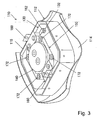
- Fig. 3 shows the airbag module 110 viewed from the back.
- the link mechanism 150 is fixed to the retainer 130 with the four guide nuts 172 and the bag ring 120.
- the guide nuts 172 and the bag ring 120 are also used as fixing means for fixing the inflator 140 to the retainer 130.
- the guide nuts 172 and the bag ring 120 (a bolt-nut structure) are used as both fixing means for fixing the link mechanism 150 to the retainer 130 close to the horn pad 112 and fixing means for fixing the inflator 140 to the retainer 130 close to the horn pad 112.
- the guide nuts 172 and the bag ring 120 serve as "the first fixing means" and "the second fixing means” of the invention.
- a rivet structure can be used.
- the retainer 130 has a first horn switch contact 132 that constructs a horn switch.
- the bracket 160 has a second horn switch contact 162 that constructs the horn switch.
- the first horn switch contact 132 and the second horn switch contact 162 come into contact with each other via the link mechanism 150 that constructs the horn switch to turn on the horn switch, thereby blowing the horn.
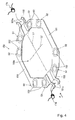
- Fig. 4 is a perspective view of the link mechanism 150 according to the embodiment.
- Fig. 5 is an enlarged view of the part of the link mechanism 150 in position S2 of Fig. 4.
- the link mechanism 150 includes a pair of right and left (bilaterally symmetrical) plate-like horn plates 151.
- the horn plates 151 correspond to "the multiple horn plates" of the invention.
- the bilaterally symmetrical right and left horn plates 151 are effective to reduce the cost because they can be used in common.
- Each horn plate 151 has four through holes 152 in total.
- the horn plates 151 are joined together with joint members 153 at the ends 151a.
- the horn plates 151 joined with the joint members 153 form a ring shape having a central hole 150a.
- the central hole 150a is fitted on the projection of the inflator 140 disposed adjacent to the horn plates 151.
- the pair of right and left horn plates 151 are disposed in a ring shape along the outline of the horn pad 112 in plan view.
- the central hole 150a of the horn plates 151 corresponds to "the central hole” of the invention.
- the inflator 140 corresponds to "the horn-plate adjacent member" of the invention.
- the joint members 153 that join the horn plates 151 have two coil springs 174 for elastically biasing the both ends 151a of the horn plates 151.
- the coil springs 174 correspond to "the biasing means" of the invention.
- each through hole 152 has a circular part 152a and notches 152b at two places of the outer periphery of the circular part 152a.
- the notches 152b are formed on the axis (axis L2 in Figs. 4 and 5) orthogonal to the axis (axis L1 in Fig. 4) of the horn plates 151.
- a first insulator 154 is fitted from above in Fig. 5 and a second insulator 155 is fitted from below in Fig. 5.
- the first insulator 154 has a substantially cylindrical main body 154a having a hole 154d, claws 154b extending from two places of the main body 154a, and semicircular projections 154c extending from two places of the main body 154a.
- the second insulator 155 has a substantially cylindrical main body 155a having a hole 155d, claws 155b extending from two places of the main body 155a, and semicircular projections 155c extending from two places of the main body 155a. Both the first insulator 154 and the second insulator 155 are made of resin.
- the claws 154b of the first insulator 154 are fitted in the notches 152b, and the claws 155b of the second insulator 155 are fitted in the notches 152b. Since the claws 154b of the first insulator 154 are fitted in the main body 155a of the second insulator 155, and the claws 155b of the second insulator 155 are fitted in the main body 154a of the first insulator 154, the first insulator 154 and the second insulator 155 are crimped to the horn plates 151 from both sides.
- the semicircular projections 154c that project downward from the main body 154a of the first insulator 154 are in contact with the upper surface of the horn plates 151, while the semicircular projections 155c that project upward from the main body 155a of the second insulator 155 are in contact with the lower surface of the horn plates 151.
- the horn plates 151 are thus clamped from both sides by the first insulator 154 and the second insulator 155.
- the projections 154c of the first insulator 154 and the projections 155c of the second insulator 155 extend longitudinally along the axis L2.
- the hole 154d of the first insulator 154 and the hole 155d of the second insulator 155 are disposed on top on one another at the upper part and the lower part of the through holes 152, forming a through hole as a whole.
- the through hole is used to pass the guide nut (the guide nut 172 in Fig. 2) for fixing the first insulator 154 and the second insulator 155 to the retainer 130 and the guide bolt (the guide bolt 170 in Fig. 2) for fixing them to the bracket 160 adjacent to the steering wheel 101 therethrough.
- the positions of the first insulator 154 and the second insulator 155 are opposite vertically from that in position S2. Specifically, in the through hole 152 at position S1, the second insulator 155 is fitted from above in Fig. 5; the first insulator 154 is fitted from below in Fig. 5.
- Figs. 6 and 7 show the link mechanism 150 in Fig. 4 viewed from arrow A, with the first insulators 154 and the second insulators 155 crimped to the horn plates 151.
- Fig. 6 shows a state before the horn pad 112 is depressed; and
- Fig. 7 shows a state when the horn pad 112 is depressed.
- Figs. 6 and 7 show the link mechanism 150 in Fig. 4 upside down.
- the link mechanism 150 is interposed between the steering wheel 101 and the retainer 130.
- the horn plates 151 are clamped at the positions of the through holes 152 by the projections 154c of the first insulator 154 and the projections 155c of the second insulator 155.
- the first insulator 154 and the second insulator 155 that clamp the horn plate 151 from both sides are fixed to the bracket 160 adjacent to the steering wheel 101 with the guide bolt (the guide bolt 170 in Fig. 2) fitted in the through hole 152.
- the first insulator 154 and the second insulator 155 at position S1 serve as "the first support means” and "the first clamp means” of the invention.
- the first insulator 154 and the second insulator 155 that clamp the horn plate 151 from both sides are fixed to the retainer 130 with the guide nut (the guide nut 172 in Fig. 2) fitted in the through hole 152.
- the first insulator 154 and the second insulator 155 at position S2 serve as "the second support means” and "the second clamp means” in the invention.
- the horn plates 151 can rotate around the rotation shaft 153a (which corresponds to "the rotation shaft” in the invention) of the joint member 153, whose ends 151a are elastically biased in the direction of arrow 10 or arrow 12 by the coil springs 174.
- the coil springs 174 have the function of elastically biasing the horn plates 151 so as to rotate in the direction opposite to arrow 14 or arrow 16 in Fig. 6 (which corresponds to "the first rotating direction” in the invention).
- the rotation shaft 153a of the joint member 153 has a cylindrical mounting part, on which the winding part of the coil spring 174 is fitted to fix the coil spring 174 to the joint member 153.
- the horn plates 151 can rotate in a specified direction (in the direction of arrow 14 or arrow 16 in Fig. 6) around the rotation shaft 153a while being clamped by the projection 154c of the first insulator 154 and the projection 155c of the second insulator 155.
- the horn plates 151 rotate in the direction of arrow 14 or arrow 16 (which corresponds to "the second rotating direction in the invention") against the elastically biasing force of the coil spring 174 around the rotation shaft 153a of the joint member 153.
- the first horn switch contact 132 of the retainer 130 and the second horn switch contact 162 of the bracket 160 move relatively in the direction in which they come close to each other. Since the first horn switch contact 132 and the second horn switch contact 162 come into contact with each other, the horn switch is turned on to blow the horn.
- the horn plates 151 rotate in the direction opposite to arrow 14 or arrow 16 by the elastically biasing force of the coil spring 174 around the rotation shaft 153a of the joint member 153 while being clamped by the projection 154c of the first insulator 154 and the projection 155c of the second insulator 155.
- the horn plate 151 returns from the state shown in Fig. 7 to the state shown in Fig. 6.
- the first horn switch contact 132 of the retainer 130 and the second horn switch contact 162 of the bracket 160 shown in Fig. 2, move relatively in the direction in which they separate from each other. Since the contact of the first horn switch contact 132 and the second horn switch contact 162 is released, the horn switch is turned off to stop the blow of the horn.
- the guide nuts 172 and the bag ring 120 serve as both fixing means for fixing the link mechanism 150 to the retainer 130 and fixing means for fixing the inflator 140 to the retainer 130, the number of components can be reduced, increasing the versatility of the components to decrease the cost, thereby achieving the rationalization of the device.
- the motion of the horn pad (module cover) 112 during the operation of the horn is limited to one direction by the rotation of the horn plates 151 in a specified direction (in the direction of arrow 14 or arrow 16 in Fig. 6).
- the embodiment uses a structure in which the pair of right and left horn plates 151 is disposed in ring form along the outline of the horn pad 112 in plan view.
- the pressure by the depression is applied evenly onto the horn pad 112, allowing the pressure required to blow the horn to be maintained constant irrespective of the depression position of the horn pad 112, thus smoothing the motion (increasing the operability of the horn).
- the gap between the outer periphery of the horn pad 112 and the steering wheel 101 can be minimized, enhancing the appearance of the steering device.
- the central hole 150a formed by the horn plates 151 is fitted on the projection of the inflator 140, the space in which the existing airbag module 110 is to be disposed can be used effectively, and the structure in which the horn plates 151 are disposed around the inflator 140 is particularly effective in reducing the height. This is therefore advantageous in reducing the height of an airbag system and a steering device to achieve size reduction.
- the fixing means for fixing the link mechanism 150 to the retainer 130 is also used as the fixing means for fixing the inflator 140 to the retainer 130.
- the invention may use a structure in which the fixing means for fixing the link mechanism 150 to the retainer 130 is also used as means for fixing another member adjacent to the horn pad 112, other than the inflator 140, to the retainer 130.
- the link mechanism is constructed of two horn plates.
- the invention may construct the ling mechanism by combining three or more horn plates as appropriate.
- the foregoing embodiment has been described for the case in which the horn plates are fitted on the projection of the inflator 140 adjacent to the horn plates through the central hole.
- the invention may use a structure in which the horn plates are not fitted on the projection of the inflator 140.
- the coil springs 174 are used as biasing means for biasing the horn plates 151
- the invention may use other means as the biasing means, such as a leaf spring with a known structure, a damper mechanism (using air pressure or fluid pressure), and means using the restoring force of the material itself.
- the invention may use the horn pad 112 only for operating the horn, separately from the airbag cover.
- the horn pad 112 operates together with the member on the retainer 130 side
- the invention may have a structure in which the horn pad 112 operates in isolation from the member on the retainer 130 side, that is, a so-called cover floating (pad floating) type in which the horn pad 112 floats on the retainer 130.
- the invention is a technique applicable to the structure of the steering device of vehicles other than a car, for example, vessels and trains.
Landscapes
- Physics & Mathematics (AREA)
- Acoustics & Sound (AREA)
- Engineering & Computer Science (AREA)
- Mechanical Engineering (AREA)
- Steering Controls (AREA)
- Air Bags (AREA)
- Push-Button Switches (AREA)
Abstract
Description
- The present invention relates to a construction of a horn switch gear mounted to a steering wheel for vehicles, and an airbag system or steering device employing the same.
- A steering device structure in which a horn mechanism is mounted to a steering wheel for vehicles is known (for example, see Japanese Unexamined Patent Application Publication No. 10-100832) .
- The steering device described in Japanese Unexamined Patent Application Publication No. 10-100832 is constructed such that when an airbag cover that is a depression part is depressed by a vehicle's occupant, a moving contact is brought into contact with a fixed contact, operating the horn mechanism to blow a horn.
- Japanese Unexamined Patent Application Publication No. 10-100832 presents a concrete structure in which a horn mechanism is mounted on a steering wheel for a vehicle. This type of gear has a keen demand for a technique to achieve rationalization by minimizing the number of components.
- The present invention has been made in light of such circumstances, and has as an object the provision of a technique advantageous in reducing the number of components in a horn switch gear mounted to a steering wheel for vehicles.
- In order to achieve the above-mentioned object, the present invention has been made. The invention can be applied to a construction technique for a horn switch gear mounted to a steering wheel for vehicles such as cars.
- More specifically, this object is achieved by a horn switch gear according to
Claim 1, an airbag system according to Claim 6, and a steering device according to Claim 7. The dependent claims define preferred or advantageous embodiments of the invention. - According to an aspect of the invention, a horn switch gear is provided.
- The horn switch gear according to this aspect of the invention is in use provided in the position on a steering wheel for vehicles at which a steering-wheel side member and a depression-part side member are opposed to each other. The horn switch gear has a structure in which a first horn switch contact and a second horn switch contact are brought into contact with each other by the depression of a depression part at operation of a horn to blow the horn, and in which the contact of the first horn switch contact and the second horn switch contact is released by canceling the depression of the depression part to release the operation of the horn.
- Here the term "depression part" typically includes a module cover (module pad) that covers the airbag of the steering wheel from the occupant side, a horn operating cover used only to activate the horn, and a horn operating button (switch). The term "steering-wheel side member" broadly includes the steering wheel itself and various members fixed to the steering wheel. The term "depression-part side member" broadly includes a depression part that is directly depressed at depression of the horn and various members fixed to the depression part.
- The horn switch gear according to the invention has a structure in which the gear is designed to be fixed to the depression-part side member via first fixing means, and the first fixing means is designed to also be used as second fixing means for fixing a plurality of the depression-part side members. As the first fixing means and the second fixing means, typically, a bolt-nut structure, a rivet structure, or the like is used.
- Since the horn switch gear according to this aspect of the invention uses the first fixing means also as the second fixing means, the number of components can be reduced, increasing the versatility of the components to reduce the cost, thereby achieving rationalization.
- According to another aspect of the invention, a horn switch gear includes at least a plurality of plate-like horn plates; first support means; second support means; and biasing means in the position where the steering-wheel side member and the depression-part side member are opposed to each other.
- The plurality of plate-like horn plates of this aspect of the invention is joined together with a rotation shaft and is allowed to rotate around the rotation shaft.
- The first support means of this aspect of the invention supports a first support section of the horn plates and is fixed to the steering-wheel side member. In other words, the horn plates are fixed to the steering-wheel side member via the first support means. The second support means fixes a second support section of the horn plates, different from the first support section, and, in use, is fixed to the depression-part side member via the first fixing means. In other words, in use, the horn plates are fixed to the depression-part side member via the first support means and the second support means. Here the term "support the horn plates" broadly includes a structure in which the horn plates are clamped from both sides and a structure in which the horn plates are supported from the top or bottom.
- The biasing means of this aspect of the invention is a means for biasing the horn plates so as to rotate around the rotation shaft in a first rotating direction. The biasing means only has to have a biasing force that rotates the horn plates in the first rotating direction and its biasing position is not limited. For example, the biasing means may directly bias the horn plates themselves or, alternatively, the biasing means may bias the rotation shaft of the horn plates. As the biasing means, a spring, a damper mechanism, and means using the restoring force of the material itself may be used.
- According to this aspect of the invention, the depression-part side member is brought close to the steering-wheel side member by the depression of the depression part to move the first support means and the second support means relatively. At that time, the horn plates rotate in a second rotating direction opposite to the first rotating direction around the rotation shaft against the biasing force of the biasing means, with the first support section supported to the steering wheel side by the first support means and the second support section supported to the depression part side by the second support means. Thus the first horn switch contact and the second horn switch contact are brought into contact with each other to blow the horn. On the other hand, the depression-part side member is separated from the steering-wheel side member by releasing the depression of the depression part to move the first support means and the second support means relatively. At that time, the horn plates rotate in the first rotating direction around the rotation shaft by the biasing force of the biasing means, with the first support section supported to the steering wheel side by the first support means and the second support section supported to the depression part side by the second support means. Thus the contact between the first horn switch contact and the second horn switch contact is released to stop the blow of the horn. The direction in which the first support means and the second support means move relatively at depression of the depression part or cancellation of the depression may either agree with the relative moving direction of the depression-part side member and the steering-wheel side member or may be different from it.
- With the horn switch gear according to this aspect of the invention, the horn plates rotate only in the first rotating direction or the second rotating direction around the rotation shaft, with the first support section supported to the steering wheel side by the first support means and the second support section supported to the depression part side by the second support means. Accordingly, the motion of the depression part is limited to one direction at the operation of the horn. Accordingly, whichever part of the depression part such as the center or the end, the occupant of the vehicle depresses, the pressure by the depression is applied evenly onto the depression part, allowing the pressure required to blow the horn to be maintained constant irrespective of the depression position of the depression part. Consequently, the operability of the horn can be improved by smoothing the motion of the depression part.
- Also, since the motion of the depression part at the operation of the horn is limited to one direction, the gap formed between the outer periphery of the depression part and the steering wheel can be minimized, enhancing the appearance.
- According to yet another aspect of the invention, the plurality of horn plates may be constructed of a pair of right and left horn plates. This structure reduces the cost by sharing two horn plates.
- According to yet another aspect of the invention, the plurality of horn plates may be joined together to form a ring shape having a central hole, and the central hole is fitted on a horn-plate adjacent member. Here the term "the horn-plate adjacent member" broadly includes members adjacent to the horn plates with the horn plates assembled. A typical example of the horn-plate adjacent member is an inflator that is disposed in a position above and adjacent to the horn plates and supplies inflation gas to the airbag.
- The structure according to this aspect of the invention can decrease the size of the devices in the direction in which the horn plates and the horn-plate adjacent member are adjacent to each other, achieving size reduction.
- According to yet another aspect of the invention, the first support means may include first clamp means and the second support means may include second clamp means. The first clamp means is fixed to the steering-wheel side member while clamping the first support section of each horn plate from the top and bottom of the plate and allows the rotation of the horn plates around the rotation shaft in the clamped state. The second clamp means is fixed to the depression-part side member while clamping the second support section of each horn plate from the top and bottom of the plate and allows the rotation of the horn plates around the rotation shaft in the clamped state.
- With this structure, the horn plates are securely supported while being clamped from the top and bottom, further smoothing the rotation around the rotation shaft.
- Further, according to another aspect of the invention, an airbag system is provided, which includes the horn switch gear according to any one aspect of the invention; a vehicle airbag; a retainer; an inflator; an airbag cover; and a horn operating member. The vehicle airbag has the function of deploying in an occupant protection region in a collision. The retainer has the function of accommodating the vehicle airbag folded in a desired form in advance. The inflator serves as gas supply means for supplying inflation gas to the vehicle airbag. The airbag cover has the function of covering the part of the vehicle airbag adjacent to the occupant. In a vehicle collision, the airbag cover is cleaved by the deploying force of the vehicle airbag, allowing the vehicle airbag to deploy in the occupant protection region. The horn operating member is a member that is operated by the occupant when the horn is activated. In the airbag system according to the invention, the horn is activated by the depression of the horn operating member serving as the depression part and the operation of the horn is cancelled by canceling the depression of the horn operating member. The horn operating member typically includes a pad member, a button, and a switch.
- According to this airbag system, the number of components of the horn switch gear in the airbag system is reduced.
- In the airbag system, the horn operating member may be provided only to operate the horn in isolation from the airbag cover or, alternatively, it may also be used as the airbag cover. When the horn operating member is also used as the airbag cover, the horn operating member may operate together with the retainer side member by depression or, alternatively, may operate in isolation from the retainer side member. In other words, the horn operating member may be of a so-called cover floating (pad floating) type in which the horn operating member floats on the retainer.
- According to another aspect of the invention, a steering device is provided, which includes a steering wheel for steering a vehicle, to which the horn switch gear according to any one aspect of the invention is mounted; a vehicle airbag; a retainer; an inflator; an airbag cover; and a horn operating member. Those components are disposed inside the outline of the steering wheel. The components, such as the vehicle airbag, the retainer, the inflator, the airbag cover, and the horn operating member, have substantially the same structure as those described for the airbag system above. In the steering device, the horn is activated by the depression of the horn operating member serving as the depression part and the operation of the horn is cancelled by canceling the depression of the horn operating member.
- According to this aspect of the invention, there is provided a steering device in which the number of components of the horn switch gear is reduced.
- As has been described, in the horn switch gear for vehicles according to the invention, since the first fixing means for fixing the horn switch gear to the depression-part side member is designed to be used as the second fixing means for fixing the plurality of depression-part side members, the number of the components can be reduced.
- An embodiment of the steering device of the present invention will be specifically described hereinafter with reference to the drawings.
- Fig. 1 is a plan view showing the appearance of a steering device according to an embodiment of the invention.
- Fig. 2 is an exploded perspective view of an airbag module in Fig. 1.
- Fig. 3 is a perspective view of the airbag module in Fig. 1, viewed from the back.
- Fig. 4 is a perspective view of a link mechanism according to the embodiment.
- Fig. 5 is an enlarged view of the part of the link mechanism in position S2 of Fig. 4.
- Fig. 6 is a diagram of the link mechanism in Fig. 4 viewed from arrow A, showing a state before a horn pad is depressed
- Fig. 7 is a diagram of the link mechanism in Fig. 4 viewed from arrow A, showing a state when the horn pad is depressed.
- Referring to Figs. 1 to 7, a
steering device 100 for cars, an embodiment of the steering device of the invention, will be described. - Fig. 1 is a plan view showing the appearance of the
steering device 100 of this embodiment. As shown in Fig. 1, thesteering device 100 of this embodiment principally includes asteering wheel 101 for an occupant to use for steering a vehicle, anairbag module 110 covered with ahorn pad 112 inside the outline of thesteering wheel 101, and a horn switch to be described later. Thesteering wheel 101 is constructed such that a ring-shaped metal core is coated with urethane resin. In thesteering device 100, thehorn pad 112 has the function of activating the horn switch by depression and also the function of covering the occupant side of anairbag 118, to be described later, and is also called "a module cover." Thehorn pad 112 serves as "the depression part" of the invention. - Fig. 2 is an exploded perspective view of the
airbag module 110 of thesteering device 100. As shown in Fig. 2, thehorn pad 112 includes a coverflat part 114 serving as depression part to be depressed in operating the horn and aleg 116 that rises upright from the coverflat part 114. Anaccommodation space 116a partitioned by theleg 116 of thehorn pad 112 accommodates principal components such as theairbag 118, abag ring 120, aretainer 130, aninflator 140, alink mechanism 150, and abracket 160 in modules on the back of thehorn pad 112. Theairbag module 110 serves as "the airbag system" of the invention. - The
airbag 118 deploys toward an occupant protection region in a collision. Theairbag 118 corresponds to "the vehicle airbag" of the invention. Theairbag 118 is mounted to theretainer 130 via thebag ring 120. Theairbag 118 that is folded in a specified form in advance is accommodated in theretainer 130. Theinflator 140 has the function of supplying inflation gas to theairbag 118. - The
link mechanism 150 is disposed on the part at which thebracket 160 as the steering wheel (101) side member and theretainer 130 as the horn pad (112) (depression part) side member are opposed. As will be described in detail later, thelink mechanism 150 is fixed to thebracket 160 withguide bolts 170 to be screwed in the thread grooves of thebracket 160 and fixed to the fixing part of thesteering wheel 101 via thebracket 160. Furthermore, thelink mechanism 150 is fixed to thebag ring 120 withguide nuts 172 to be screwed on thethreads 122 of thebag ring 120, with theretainer 130 and the inflator 140 interposed therebetween. - Fig. 3 shows the
airbag module 110 viewed from the back. As shown in Fig. 3, thelink mechanism 150 is fixed to theretainer 130 with the fourguide nuts 172 and thebag ring 120. Theguide nuts 172 and thebag ring 120 are also used as fixing means for fixing the inflator 140 to theretainer 130. Specifically, according to the embodiment, theguide nuts 172 and the bag ring 120 (a bolt-nut structure) are used as both fixing means for fixing thelink mechanism 150 to theretainer 130 close to thehorn pad 112 and fixing means for fixing the inflator 140 to theretainer 130 close to thehorn pad 112. Theguide nuts 172 and thebag ring 120 serve as "the first fixing means" and "the second fixing means" of the invention. In place of the bolt-nut structure, a rivet structure can be used. - The
retainer 130 has a firsthorn switch contact 132 that constructs a horn switch. Thebracket 160 has a secondhorn switch contact 162 that constructs the horn switch. The firsthorn switch contact 132 and the secondhorn switch contact 162 come into contact with each other via thelink mechanism 150 that constructs the horn switch to turn on the horn switch, thereby blowing the horn. - Referring to Figs. 4 and 5, the specific structure of the
link mechanism 150 will be described. Fig. 4 is a perspective view of thelink mechanism 150 according to the embodiment. Fig. 5 is an enlarged view of the part of thelink mechanism 150 in position S2 of Fig. 4. - As shown in Fig. 4, the
link mechanism 150 includes a pair of right and left (bilaterally symmetrical) plate-like horn plates 151. Thehorn plates 151 correspond to "the multiple horn plates" of the invention. The bilaterally symmetrical right and lefthorn plates 151 are effective to reduce the cost because they can be used in common. Eachhorn plate 151 has four throughholes 152 in total. Thehorn plates 151 are joined together withjoint members 153 at theends 151a. Thehorn plates 151 joined with thejoint members 153 form a ring shape having acentral hole 150a. Thecentral hole 150a is fitted on the projection of the inflator 140 disposed adjacent to thehorn plates 151. Although not shown in the drawing, the pair of right and lefthorn plates 151 are disposed in a ring shape along the outline of thehorn pad 112 in plan view. Thecentral hole 150a of thehorn plates 151 corresponds to "the central hole" of the invention. Theinflator 140 corresponds to "the horn-plate adjacent member" of the invention. - As the details will be described later, the
joint members 153 that join thehorn plates 151 have twocoil springs 174 for elastically biasing the both ends 151a of thehorn plates 151. The coil springs 174 correspond to "the biasing means" of the invention. - As shown in Fig. 5, each through
hole 152 has acircular part 152a andnotches 152b at two places of the outer periphery of thecircular part 152a. Thenotches 152b are formed on the axis (axis L2 in Figs. 4 and 5) orthogonal to the axis (axis L1 in Fig. 4) of thehorn plates 151. In each throughhole 152 at position S2 in Fig. 4, afirst insulator 154 is fitted from above in Fig. 5 and asecond insulator 155 is fitted from below in Fig. 5. - The
first insulator 154 has a substantially cylindricalmain body 154a having ahole 154d,claws 154b extending from two places of themain body 154a, andsemicircular projections 154c extending from two places of themain body 154a. Thesecond insulator 155 has a substantially cylindricalmain body 155a having ahole 155d,claws 155b extending from two places of themain body 155a, andsemicircular projections 155c extending from two places of themain body 155a. Both thefirst insulator 154 and thesecond insulator 155 are made of resin. - When the
first insulator 154 and thesecond insulator 155 are fitted into each throughhole 152, theclaws 154b of thefirst insulator 154 are fitted in thenotches 152b, and theclaws 155b of thesecond insulator 155 are fitted in thenotches 152b. Since theclaws 154b of thefirst insulator 154 are fitted in themain body 155a of thesecond insulator 155, and theclaws 155b of thesecond insulator 155 are fitted in themain body 154a of thefirst insulator 154, thefirst insulator 154 and thesecond insulator 155 are crimped to thehorn plates 151 from both sides. In this crimped state, thesemicircular projections 154c that project downward from themain body 154a of thefirst insulator 154 are in contact with the upper surface of thehorn plates 151, while thesemicircular projections 155c that project upward from themain body 155a of thesecond insulator 155 are in contact with the lower surface of thehorn plates 151. Thehorn plates 151 are thus clamped from both sides by thefirst insulator 154 and thesecond insulator 155. Theprojections 154c of thefirst insulator 154 and theprojections 155c of thesecond insulator 155 extend longitudinally along the axis L2. This allows the motion of thehorn plates 151 relative to thefirst insulator 154 and thesecond insulator 155 by the cooperation of theprojections 154c and theprojections 155c, with thefirst insulator 154 and thesecond insulator 155 crimped to thehorn plates 151. The motion follows the extending direction of theprojections 154c and theprojections 155c, thus being limited to the longitudinal section of the axis L2 on which thenotches 152b of the throughhole 152 are provided. - In this crimped state, the
hole 154d of thefirst insulator 154 and thehole 155d of thesecond insulator 155 are disposed on top on one another at the upper part and the lower part of the throughholes 152, forming a through hole as a whole. The through hole is used to pass the guide nut (theguide nut 172 in Fig. 2) for fixing thefirst insulator 154 and thesecond insulator 155 to theretainer 130 and the guide bolt (theguide bolt 170 in Fig. 2) for fixing them to thebracket 160 adjacent to thesteering wheel 101 therethrough. - For each through
hole 152 at position S1 in Fig. 4, or the throughhole 152 closer to the end of the horn plate than to position S2, the positions of thefirst insulator 154 and thesecond insulator 155 are opposite vertically from that in position S2. Specifically, in the throughhole 152 at position S1, thesecond insulator 155 is fitted from above in Fig. 5; thefirst insulator 154 is fitted from below in Fig. 5. - Figs. 6 and 7 show the
link mechanism 150 in Fig. 4 viewed from arrow A, with thefirst insulators 154 and thesecond insulators 155 crimped to thehorn plates 151. Fig. 6 shows a state before thehorn pad 112 is depressed; and Fig. 7 shows a state when thehorn pad 112 is depressed. Figs. 6 and 7 show thelink mechanism 150 in Fig. 4 upside down. - As shown in Fig. 6, the
link mechanism 150 is interposed between thesteering wheel 101 and theretainer 130. In thelink mechanism 150, thehorn plates 151 are clamped at the positions of the throughholes 152 by theprojections 154c of thefirst insulator 154 and theprojections 155c of thesecond insulator 155. - In the through
hole 152 on the inside of Fig. 6, or at positions S1 in Fig. 4 (which corresponds to "the first support section" in the invention), thefirst insulator 154 and thesecond insulator 155 that clamp thehorn plate 151 from both sides are fixed to thebracket 160 adjacent to thesteering wheel 101 with the guide bolt (theguide bolt 170 in Fig. 2) fitted in the throughhole 152. Thefirst insulator 154 and thesecond insulator 155 at position S1 serve as "the first support means" and "the first clamp means" of the invention. - On the other hand, in the through
hole 152 on the outside in Fig. 6, or at position S2 in Fig. 4 (which corresponds to "the second support section" of the invention), thefirst insulator 154 and thesecond insulator 155 that clamp thehorn plate 151 from both sides are fixed to theretainer 130 with the guide nut (theguide nut 172 in Fig. 2) fitted in the throughhole 152. Thefirst insulator 154 and thesecond insulator 155 at position S2 serve as "the second support means" and "the second clamp means" in the invention. - The
horn plates 151 can rotate around therotation shaft 153a (which corresponds to "the rotation shaft" in the invention) of thejoint member 153, whoseends 151a are elastically biased in the direction ofarrow 10 orarrow 12 by the coil springs 174. In other words, the coil springs 174 have the function of elastically biasing thehorn plates 151 so as to rotate in the direction opposite toarrow 14 orarrow 16 in Fig. 6 (which corresponds to "the first rotating direction" in the invention). Therotation shaft 153a of thejoint member 153 has a cylindrical mounting part, on which the winding part of thecoil spring 174 is fitted to fix thecoil spring 174 to thejoint member 153. - When the
horn pad 112 is depressed to blow the horn in the state of Fig. 6, the load is applied to the part substantially in the center of each horn plate 151 (the right and left ends in Fig. 6) of thelink mechanism 150 via theretainer 130. At that time, the lower surface of theretainer 130 moves toward the upper surface of the steering wheel 101 (downward in Fig. 6), and with this motion, thefirst insulator 154 and thesecond insulator 155 disposed outside in Fig. 6, which are fixed to theretainer 130, are also moved downward in Fig. 6. In other words, thefirst insulator 154 and thesecond insulator 155 disposed outside in Fig. 6 (at position S2 in Fig. 4) move relative to thefirst insulator 154 and thesecond insulator 155 disposed inside in Fig. 6 (at position S1 in Fig. 4). Accordingly, thehorn plates 151 can rotate in a specified direction (in the direction ofarrow 14 orarrow 16 in Fig. 6) around therotation shaft 153a while being clamped by theprojection 154c of thefirst insulator 154 and theprojection 155c of thesecond insulator 155. Thus, as shown in Fig. 7, thehorn plates 151 rotate in the direction ofarrow 14 or arrow 16 (which corresponds to "the second rotating direction in the invention") against the elastically biasing force of thecoil spring 174 around therotation shaft 153a of thejoint member 153. At that time, according to the embodiment, the firsthorn switch contact 132 of theretainer 130 and the secondhorn switch contact 162 of thebracket 160, shown in Fig. 2, move relatively in the direction in which they come close to each other. Since the firsthorn switch contact 132 and the secondhorn switch contact 162 come into contact with each other, the horn switch is turned on to blow the horn. - When the depression of the
horn pad 112 is released to cancel the operation of the horn in the state of Fig. 7, the load applied to thehorn plates 151 by depression is decreased. At that time, the lower surface of theretainer 130 moves in the direction separating from the upper surface of the steering wheel 101 (upward in Fig. 7), with which thefirst insulator 154 and thesecond insulator 155 disposed outside in Fig. 7 (at position S2 in Fig. 4), which are fixed to theretainer 130, are also moved upward in Fig. 7. Accordingly, thehorn plates 151 rotate in the direction opposite toarrow 14 orarrow 16 by the elastically biasing force of thecoil spring 174 around therotation shaft 153a of thejoint member 153 while being clamped by theprojection 154c of thefirst insulator 154 and theprojection 155c of thesecond insulator 155. Thus, thehorn plate 151 returns from the state shown in Fig. 7 to the state shown in Fig. 6. At that time, according to the embodiment, the firsthorn switch contact 132 of theretainer 130 and the secondhorn switch contact 162 of thebracket 160, shown in Fig. 2, move relatively in the direction in which they separate from each other. Since the contact of the firsthorn switch contact 132 and the secondhorn switch contact 162 is released, the horn switch is turned off to stop the blow of the horn. - As has been described, in the steering device that mounts the
link mechanism 150 of the embodiment, since theguide nuts 172 and thebag ring 120 serve as both fixing means for fixing thelink mechanism 150 to theretainer 130 and fixing means for fixing the inflator 140 to theretainer 130, the number of components can be reduced, increasing the versatility of the components to decrease the cost, thereby achieving the rationalization of the device. - According to the embodiment, the motion of the horn pad (module cover) 112 during the operation of the horn is limited to one direction by the rotation of the
horn plates 151 in a specified direction (in the direction ofarrow 14 orarrow 16 in Fig. 6). Also, the embodiment uses a structure in which the pair of right and lefthorn plates 151 is disposed in ring form along the outline of thehorn pad 112 in plan view. Accordingly, whichever part of thehorn pad 112 such as the center or the end, the occupant of the vehicle depresses, the pressure by the depression is applied evenly onto thehorn pad 112, allowing the pressure required to blow the horn to be maintained constant irrespective of the depression position of thehorn pad 112, thus smoothing the motion (increasing the operability of the horn). - According to the embodiment, since the motion of the
horn pad 112 is limited to one direction during the operation of the horn, the gap between the outer periphery of thehorn pad 112 and thesteering wheel 101 can be minimized, enhancing the appearance of the steering device. - According to the embodiment, since the
central hole 150a formed by thehorn plates 151 is fitted on the projection of the inflator 140, the space in which the existingairbag module 110 is to be disposed can be used effectively, and the structure in which thehorn plates 151 are disposed around theinflator 140 is particularly effective in reducing the height. This is therefore advantageous in reducing the height of an airbag system and a steering device to achieve size reduction. - The invention is not limited to the foregoing embodiment but various applications and modifications can be made. For example, the following applications can be made.
- The foregoing embodiment has been described for the case in which the fixing means for fixing the
link mechanism 150 to theretainer 130 is also used as the fixing means for fixing the inflator 140 to theretainer 130. Alternatively, the invention may use a structure in which the fixing means for fixing thelink mechanism 150 to theretainer 130 is also used as means for fixing another member adjacent to thehorn pad 112, other than the inflator 140, to theretainer 130. - The foregoing embodiment has been described for the case in which the link mechanism is constructed of two horn plates. Alternatively, the invention may construct the ling mechanism by combining three or more horn plates as appropriate.
- The foregoing embodiment has been described for the case in which the horn plates are fitted on the projection of the inflator 140 adjacent to the horn plates through the central hole. Alternatively, the invention may use a structure in which the horn plates are not fitted on the projection of the
inflator 140. - Although in the embodiment the coil springs 174 are used as biasing means for biasing the
horn plates 151, the invention may use other means as the biasing means, such as a leaf spring with a known structure, a damper mechanism (using air pressure or fluid pressure), and means using the restoring force of the material itself. - Although in the embodiment the
horn pad 112 is also used as the airbag cover, the invention may use thehorn pad 112 only for operating the horn, separately from the airbag cover. Although in the embodiment thehorn pad 112 operates together with the member on theretainer 130 side, the invention may have a structure in which thehorn pad 112 operates in isolation from the member on theretainer 130 side, that is, a so-called cover floating (pad floating) type in which thehorn pad 112 floats on theretainer 130. - Although in the embodiment the structure of the steering device of a car has been described, the invention is a technique applicable to the structure of the steering device of vehicles other than a car, for example, vessels and trains.
Claims (7)
- A horn switch gear provided in use in the position on a steering wheel for vehicles at which a steering-wheel side member (160) and a depression-part side member (130) are opposed to each other, in which a first horn switch contact (132) and a second horn switch contact (162) are brought into contact with each other by the depression of a depression part (112) at operation of a horn to blow the horn, and in which the contact of the first horn switch contact (132) and the second horn switch contact (162) is released by canceling the depression of the depression part (112) to release the operation of the horn, wherein
the gear is fixed to the depression-part side member (130) via first fixing means(120, 172) the first fixing means (120, 172) being also used as second fixing means for fixing a plurality of the depression-part side members (130). - The horn switch gear according to Claim 1, comprising:a plurality of plate-like horn plates (151) that is joined together with a rotation shaft (153a) and is allowed to rotate around the rotation shaft (153a); first support means (154, 155, 170) that supports a first support section (S1) of the horn plates (151) and is fixed to the steering-wheel side member (160); second support means (154, 155, 172) that fixes a second support section (S2) of the horn plates (151), different from the first support section (S1), and is fixed to the depression-part side member (130) via the first fixing means (120, 172); and biasing means (174) that biases the horn plates (151) so as to rotate around the rotation shaft (153a) in a first rotating direction; wherein the horn switch gear is designed such thatwhen the depression-part side member (130) is brought close to the steering-wheel side member (160) by the depression of the depression part (112) to move the first support means and the second support means relatively, the horn plates (151) rotate in a second rotating direction opposite to the first rotating direction around the rotation shaft (153a) against the biasing force of the biasing means (174), with the first support section (S1) supported to the steering wheel side by the first support means (154, 155, 170) and the second support section (S2) supported to the depression part side by the second support means (154, 155, 172), to bring the first horn switch contact (132) into contact with the second horn switch contact (162); andwhen the depression-part side member (130) is separated from the steering-wheel side member (160) by releasing the depression of the depression part (112) to move the first support means and the second support means relatively, the horn plates (151) rotate in the first rotating direction around the rotation shaft (153a) by the biasing force of the biasing means (174), with the first support section (S1) supported to the steering wheel side by the first support means (154, 155, 170) and the second support section (S2) supported to the depression part side by the second support means (154, 155, 172), to release the contact between the first horn switch contact (132) and the second horn switch contact (162).
- The horn switch gear according to Claim 2, wherein
the plurality of horn plates (151) are constructed of a pair of right and left horn plates. - The horn switch gear according to Claim 2 or 3, wherein
the plurality of horn plates (151) are joined together to form a ring shape having a central hole (150a), the central hole (150a) being fitted on a horn-plate adjacent member (140). - The horn switch gear according to any one of Claims 2 to 4, wherein
the first support means (154, 155, 170) includes first clamp means (154, 155) that is fixed to the steering-wheel side member (160) while clamping the first support section (S1) of each horn plate (151) from the top and bottom of the plate and allows the rotation of the horn plates (151) around the rotation shaft (153a) in the clamped state; and
the second support means (154, 155, 172) includes second clamp means (154, 155) that is fixed to the depression-part side member (130) while clamping the second support section (S2) of each horn plate (151) from the top and bottom of the plate and allows the rotation of the horn plates (151) around the rotation shaft (153a) in the clamped state. - An airbag system comprising:the horn switch gear according to any one of Claims 1 to 5;a vehicle airbag (118) that deploys in an occupant protection region in a collision;a retainer (130) that accommodates the vehicle airbag (118) folded in a desired form in advance;an inflator (140) that supplies inflation gas to the vehicle airbag (118);an airbag cover (112) that covers the part of the vehicle airbag (118) adjacent to the occupant; anda horn operating member (112),wherein a horn is activated by the depression of the horn operating member (112) serving as the depression part and the operation of the horn is cancelled by canceling the depression of the horn operating member (112).
- A steering device comprising:a steering wheel for steering a vehicle, to which the horn switch gear according to any one of Claims 1 to 5 is mounted;a vehicle airbag (118) that deploys in an occupant protection region in a collision;a retainer (130) that accommodates the vehicle airbag (118) folded in a desired form in advance;an inflator (140) that supplies inflation gas to the vehicle airbag (118);an airbag cover (112) that covers the part of the vehicle airbag (118) adjacent to the occupant inside the outline of the steering wheel; anda horn operating member (112) provided to the steering wheel,wherein a horn is activated by the depression of the horn operating member (112) serving as the depression part and the operation of the horn is cancelled by canceling the depression of the horn operating member (112).
Applications Claiming Priority (1)
| Application Number | Priority Date | Filing Date | Title |
|---|---|---|---|
| JP2004277288A JP2006092921A (en) | 2004-09-24 | 2004-09-24 | Horn switch device, air-bag device and steering device |
Publications (2)
| Publication Number | Publication Date |
|---|---|
| EP1640214A1 true EP1640214A1 (en) | 2006-03-29 |
| EP1640214B1 EP1640214B1 (en) | 2008-02-27 |
Family
ID=35045338
Family Applications (1)
| Application Number | Title | Priority Date | Filing Date |
|---|---|---|---|
| EP05018083A Ceased EP1640214B1 (en) | 2004-09-24 | 2005-08-19 | Horn switch gear, airbag system comprising this Horn switch gear, and steering device comprising this horn switch gear |
Country Status (4)
| Country | Link |
|---|---|
| US (1) | US20060066082A1 (en) |
| EP (1) | EP1640214B1 (en) |
| JP (1) | JP2006092921A (en) |
| DE (1) | DE602005004973T2 (en) |
Families Citing this family (4)
| Publication number | Priority date | Publication date | Assignee | Title |
|---|---|---|---|---|
| US7708309B2 (en) * | 2005-10-20 | 2010-05-04 | Delphi Korea Corporation | Driver's airbag module assembly structure |
| DE102008013526B4 (en) * | 2008-03-07 | 2012-02-02 | Autoliv Development Ab | Safety arrangement and method for producing a safety arrangement |
| JP5083623B2 (en) * | 2008-05-28 | 2012-11-28 | オムロン株式会社 | Push-button switch |
| CN110143231B (en) * | 2019-05-06 | 2024-03-22 | 顺达(芜湖)汽车饰件有限公司 | Steering wheel skeleton with shock-absorbing steering wheel gasbag hanger bar |
Citations (6)
| Publication number | Priority date | Publication date | Assignee | Title |
|---|---|---|---|---|
| EP0390029A2 (en) * | 1989-03-27 | 1990-10-03 | Toyoda Gosei Co., Ltd. | Horn switch mechanism of steering wheel |
| JPH10100832A (en) | 1996-09-30 | 1998-04-21 | Sensor Technol Kk | Air bag module for driver's seat |
| US6199908B1 (en) * | 1997-01-16 | 2001-03-13 | Toyoda Gosei Co., Ltd. | Steering wheel and horn switch assembly for the steering wheel |
| EP1099604A2 (en) * | 1999-09-24 | 2001-05-16 | Gallino Plasturgia S.r.L. | "Horn actuating device for a motor-vehicle steering wheel" |
| US20040099517A1 (en) * | 2002-08-30 | 2004-05-27 | Takata-Petri Ag | Switching device for a vehicle horn |
| DE202004010098U1 (en) * | 2004-06-23 | 2004-09-23 | Takata-Petri Ag | Switch actuator for operating a road vehicle horn, uses a mechanism that prevents a tilting action |
Family Cites Families (11)
| Publication number | Priority date | Publication date | Assignee | Title |
|---|---|---|---|---|
| US5327796A (en) * | 1992-12-28 | 1994-07-12 | General Motors Corporation | Horn switch actuated by rocking air bag module |
| US5650600A (en) * | 1995-06-01 | 1997-07-22 | Trw Inc. | Horn switch for air bag module |
| US6478330B2 (en) * | 1996-08-06 | 2002-11-12 | Toyoda Gosei Co., Ltd. | Steering wheel |
| DE29805207U1 (en) * | 1998-03-23 | 1998-06-04 | TRW Automotive Safety Systems GmbH, 63743 Aschaffenburg | Steering wheel with an airbag |
| US6830263B2 (en) * | 2002-02-08 | 2004-12-14 | Key Safety Systems, Inc. | Method for attaching an airbag module |
| DE20213908U1 (en) * | 2002-09-09 | 2003-01-30 | TRW Automotive Safety Systems GmbH & Co. KG, 63743 Aschaffenburg | Airbag module and assembly from a steering wheel and an airbag module |
| DE20303116U1 (en) * | 2003-02-20 | 2003-07-17 | Takata Petri Ag | Switch with self-cleaning contacts |
| US6942247B2 (en) * | 2003-03-12 | 2005-09-13 | Delphi Technologies, Inc. | Driver airbag formed contact spring |
| KR100519231B1 (en) * | 2003-08-14 | 2005-10-06 | 현대모비스 주식회사 | Horn switch assembly |
| US7159898B2 (en) * | 2004-04-20 | 2007-01-09 | General Motors Corporation | Vehicle air bag module retention system |
| JP2006228699A (en) * | 2004-12-17 | 2006-08-31 | Takata Corp | Horn switch device, air bag device, and steering wheel |
-
2004
- 2004-09-24 JP JP2004277288A patent/JP2006092921A/en not_active Withdrawn
-
2005
- 2005-08-19 DE DE602005004973T patent/DE602005004973T2/en not_active Expired - Fee Related
- 2005-08-19 EP EP05018083A patent/EP1640214B1/en not_active Ceased
- 2005-09-15 US US11/226,238 patent/US20060066082A1/en not_active Abandoned
Patent Citations (6)
| Publication number | Priority date | Publication date | Assignee | Title |
|---|---|---|---|---|
| EP0390029A2 (en) * | 1989-03-27 | 1990-10-03 | Toyoda Gosei Co., Ltd. | Horn switch mechanism of steering wheel |
| JPH10100832A (en) | 1996-09-30 | 1998-04-21 | Sensor Technol Kk | Air bag module for driver's seat |
| US6199908B1 (en) * | 1997-01-16 | 2001-03-13 | Toyoda Gosei Co., Ltd. | Steering wheel and horn switch assembly for the steering wheel |
| EP1099604A2 (en) * | 1999-09-24 | 2001-05-16 | Gallino Plasturgia S.r.L. | "Horn actuating device for a motor-vehicle steering wheel" |
| US20040099517A1 (en) * | 2002-08-30 | 2004-05-27 | Takata-Petri Ag | Switching device for a vehicle horn |
| DE202004010098U1 (en) * | 2004-06-23 | 2004-09-23 | Takata-Petri Ag | Switch actuator for operating a road vehicle horn, uses a mechanism that prevents a tilting action |
Also Published As
| Publication number | Publication date |
|---|---|
| DE602005004973D1 (en) | 2008-04-10 |
| JP2006092921A (en) | 2006-04-06 |
| US20060066082A1 (en) | 2006-03-30 |
| EP1640214B1 (en) | 2008-02-27 |
| DE602005004973T2 (en) | 2009-03-05 |
Similar Documents
| Publication | Publication Date | Title |
|---|---|---|
| US11034374B2 (en) | Steering wheel | |
| JP5629415B2 (en) | Airbag module assembly for controlling the gap near the airbag cover | |
| JP5415125B2 (en) | Steering wheel, steering device | |
| US11305716B2 (en) | Steering wheel | |
| JP4044440B2 (en) | Inflatable airbag bolster panel holding device | |
| US11529921B2 (en) | Steering wheel | |
| JP5641639B2 (en) | handle | |
| JP7328441B2 (en) | steering wheel | |
| EP1640214B1 (en) | Horn switch gear, airbag system comprising this Horn switch gear, and steering device comprising this horn switch gear | |
| US8931799B2 (en) | Airbag device and steering wheel | |
| JPH06191413A (en) | Steering wheel | |
| JP5162234B2 (en) | Handle switch device and handle | |
| JP2006213147A (en) | Horn switch gear, airbag device and steering device | |
| US12252089B2 (en) | Steering wheel | |
| US6455792B1 (en) | Steering wheel with a moving contact | |
| JP2015037913A (en) | Air bag device | |
| JP2022155069A (en) | steering wheel | |
| KR20100031419A (en) | Airbag assembly | |
| JP2005199789A (en) | Steering device | |
| JPH08183416A (en) | Air bag device | |
| JPH08324438A (en) | Steering wheel | |
| JP2006205908A (en) | Airbag device | |
| KR20040035004A (en) | Steering wheel having a air-bag module in a vehicle | |
| JPH1120710A (en) | Steering wheel |
Legal Events
| Date | Code | Title | Description |
|---|---|---|---|
| PUAI | Public reference made under article 153(3) epc to a published international application that has entered the european phase |
Free format text: ORIGINAL CODE: 0009012 |
|
| AK | Designated contracting states |
Kind code of ref document: A1 Designated state(s): AT BE BG CH CY CZ DE DK EE ES FI FR GB GR HU IE IS IT LI LT LU LV MC NL PL PT RO SE SI SK TR |
|
| AX | Request for extension of the european patent |
Extension state: AL BA HR MK YU |
|
| 17P | Request for examination filed |
Effective date: 20060728 |
|
| 17Q | First examination report despatched |
Effective date: 20060824 |
|
| AKX | Designation fees paid |
Designated state(s): DE FR GB SE |
|
| GRAP | Despatch of communication of intention to grant a patent |
Free format text: ORIGINAL CODE: EPIDOSNIGR1 |
|
| GRAS | Grant fee paid |
Free format text: ORIGINAL CODE: EPIDOSNIGR3 |
|
| GRAA | (expected) grant |
Free format text: ORIGINAL CODE: 0009210 |
|
| AK | Designated contracting states |
Kind code of ref document: B1 Designated state(s): DE FR GB SE |
|
| REG | Reference to a national code |
Ref country code: GB Ref legal event code: FG4D |
|
| REF | Corresponds to: |
Ref document number: 602005004973 Country of ref document: DE Date of ref document: 20080410 Kind code of ref document: P |
|
| PG25 | Lapsed in a contracting state [announced via postgrant information from national office to epo] |
Ref country code: SE Free format text: LAPSE BECAUSE OF FAILURE TO SUBMIT A TRANSLATION OF THE DESCRIPTION OR TO PAY THE FEE WITHIN THE PRESCRIBED TIME-LIMIT Effective date: 20080527 |
|
| PGFP | Annual fee paid to national office [announced via postgrant information from national office to epo] |
Ref country code: DE Payment date: 20080905 Year of fee payment: 4 |
|
| EN | Fr: translation not filed | ||
| PLBE | No opposition filed within time limit |
Free format text: ORIGINAL CODE: 0009261 |
|
| STAA | Information on the status of an ep patent application or granted ep patent |
Free format text: STATUS: NO OPPOSITION FILED WITHIN TIME LIMIT |
|
| 26N | No opposition filed |
Effective date: 20081128 |
|
| PG25 | Lapsed in a contracting state [announced via postgrant information from national office to epo] |
Ref country code: FR Free format text: LAPSE BECAUSE OF FAILURE TO SUBMIT A TRANSLATION OF THE DESCRIPTION OR TO PAY THE FEE WITHIN THE PRESCRIBED TIME-LIMIT Effective date: 20081219 |
|
| GBPC | Gb: european patent ceased through non-payment of renewal fee |
Effective date: 20090819 |
|
| PG25 | Lapsed in a contracting state [announced via postgrant information from national office to epo] |
Ref country code: DE Free format text: LAPSE BECAUSE OF NON-PAYMENT OF DUE FEES Effective date: 20100302 |
|
| PG25 | Lapsed in a contracting state [announced via postgrant information from national office to epo] |
Ref country code: GB Free format text: LAPSE BECAUSE OF NON-PAYMENT OF DUE FEES Effective date: 20090819 |