EP1639934A2 - Vacuum cleaner - Google Patents
Vacuum cleaner Download PDFInfo
- Publication number
- EP1639934A2 EP1639934A2 EP05106262A EP05106262A EP1639934A2 EP 1639934 A2 EP1639934 A2 EP 1639934A2 EP 05106262 A EP05106262 A EP 05106262A EP 05106262 A EP05106262 A EP 05106262A EP 1639934 A2 EP1639934 A2 EP 1639934A2
- Authority
- EP
- European Patent Office
- Prior art keywords
- cleaned
- cleaning
- cleaner
- vacuum cleaner
- reader
- Prior art date
- Legal status (The legal status is an assumption and is not a legal conclusion. Google has not performed a legal analysis and makes no representation as to the accuracy of the status listed.)
- Withdrawn
Links
Images


Classifications
-
- A—HUMAN NECESSITIES
- A47—FURNITURE; DOMESTIC ARTICLES OR APPLIANCES; COFFEE MILLS; SPICE MILLS; SUCTION CLEANERS IN GENERAL
- A47L—DOMESTIC WASHING OR CLEANING; SUCTION CLEANERS IN GENERAL
- A47L9/00—Details or accessories of suction cleaners, e.g. mechanical means for controlling the suction or for effecting pulsating action; Storing devices specially adapted to suction cleaners or parts thereof; Carrying-vehicles specially adapted for suction cleaners
- A47L9/009—Carrying-vehicles; Arrangements of trollies or wheels; Means for avoiding mechanical obstacles
-
- A—HUMAN NECESSITIES
- A47—FURNITURE; DOMESTIC ARTICLES OR APPLIANCES; COFFEE MILLS; SPICE MILLS; SUCTION CLEANERS IN GENERAL
- A47L—DOMESTIC WASHING OR CLEANING; SUCTION CLEANERS IN GENERAL
- A47L9/00—Details or accessories of suction cleaners, e.g. mechanical means for controlling the suction or for effecting pulsating action; Storing devices specially adapted to suction cleaners or parts thereof; Carrying-vehicles specially adapted for suction cleaners
- A47L9/28—Installation of the electric equipment, e.g. adaptation or attachment to the suction cleaner; Controlling suction cleaners by electric means
-
- A—HUMAN NECESSITIES
- A47—FURNITURE; DOMESTIC ARTICLES OR APPLIANCES; COFFEE MILLS; SPICE MILLS; SUCTION CLEANERS IN GENERAL
- A47L—DOMESTIC WASHING OR CLEANING; SUCTION CLEANERS IN GENERAL
- A47L9/00—Details or accessories of suction cleaners, e.g. mechanical means for controlling the suction or for effecting pulsating action; Storing devices specially adapted to suction cleaners or parts thereof; Carrying-vehicles specially adapted for suction cleaners
- A47L9/02—Nozzles
-
- A—HUMAN NECESSITIES
- A47—FURNITURE; DOMESTIC ARTICLES OR APPLIANCES; COFFEE MILLS; SPICE MILLS; SUCTION CLEANERS IN GENERAL
- A47L—DOMESTIC WASHING OR CLEANING; SUCTION CLEANERS IN GENERAL
- A47L9/00—Details or accessories of suction cleaners, e.g. mechanical means for controlling the suction or for effecting pulsating action; Storing devices specially adapted to suction cleaners or parts thereof; Carrying-vehicles specially adapted for suction cleaners
- A47L9/28—Installation of the electric equipment, e.g. adaptation or attachment to the suction cleaner; Controlling suction cleaners by electric means
- A47L9/2805—Parameters or conditions being sensed
-
- A—HUMAN NECESSITIES
- A47—FURNITURE; DOMESTIC ARTICLES OR APPLIANCES; COFFEE MILLS; SPICE MILLS; SUCTION CLEANERS IN GENERAL
- A47L—DOMESTIC WASHING OR CLEANING; SUCTION CLEANERS IN GENERAL
- A47L9/00—Details or accessories of suction cleaners, e.g. mechanical means for controlling the suction or for effecting pulsating action; Storing devices specially adapted to suction cleaners or parts thereof; Carrying-vehicles specially adapted for suction cleaners
- A47L9/28—Installation of the electric equipment, e.g. adaptation or attachment to the suction cleaner; Controlling suction cleaners by electric means
- A47L9/2836—Installation of the electric equipment, e.g. adaptation or attachment to the suction cleaner; Controlling suction cleaners by electric means characterised by the parts which are controlled
- A47L9/2842—Suction motors or blowers
-
- A—HUMAN NECESSITIES
- A47—FURNITURE; DOMESTIC ARTICLES OR APPLIANCES; COFFEE MILLS; SPICE MILLS; SUCTION CLEANERS IN GENERAL
- A47L—DOMESTIC WASHING OR CLEANING; SUCTION CLEANERS IN GENERAL
- A47L9/00—Details or accessories of suction cleaners, e.g. mechanical means for controlling the suction or for effecting pulsating action; Storing devices specially adapted to suction cleaners or parts thereof; Carrying-vehicles specially adapted for suction cleaners
- A47L9/28—Installation of the electric equipment, e.g. adaptation or attachment to the suction cleaner; Controlling suction cleaners by electric means
- A47L9/2836—Installation of the electric equipment, e.g. adaptation or attachment to the suction cleaner; Controlling suction cleaners by electric means characterised by the parts which are controlled
- A47L9/2852—Elements for displacement of the vacuum cleaner or the accessories therefor, e.g. wheels, casters or nozzles
-
- A—HUMAN NECESSITIES
- A47—FURNITURE; DOMESTIC ARTICLES OR APPLIANCES; COFFEE MILLS; SPICE MILLS; SUCTION CLEANERS IN GENERAL
- A47L—DOMESTIC WASHING OR CLEANING; SUCTION CLEANERS IN GENERAL
- A47L9/00—Details or accessories of suction cleaners, e.g. mechanical means for controlling the suction or for effecting pulsating action; Storing devices specially adapted to suction cleaners or parts thereof; Carrying-vehicles specially adapted for suction cleaners
- A47L9/28—Installation of the electric equipment, e.g. adaptation or attachment to the suction cleaner; Controlling suction cleaners by electric means
- A47L9/2857—User input or output elements for control, e.g. buttons, switches or displays
-
- A—HUMAN NECESSITIES
- A47—FURNITURE; DOMESTIC ARTICLES OR APPLIANCES; COFFEE MILLS; SPICE MILLS; SUCTION CLEANERS IN GENERAL
- A47L—DOMESTIC WASHING OR CLEANING; SUCTION CLEANERS IN GENERAL
- A47L9/00—Details or accessories of suction cleaners, e.g. mechanical means for controlling the suction or for effecting pulsating action; Storing devices specially adapted to suction cleaners or parts thereof; Carrying-vehicles specially adapted for suction cleaners
- A47L9/28—Installation of the electric equipment, e.g. adaptation or attachment to the suction cleaner; Controlling suction cleaners by electric means
- A47L9/2894—Details related to signal transmission in suction cleaners
Definitions
- the present invention relates to a vacuum cleaner operable in a plurality of cleaning modes and a method of using the same.
- Vacuum cleaners are known the art and one such device is on the market.
- One is disclosed in Korean Unexamined Patent Publication No. 2003-0056826 comprising a cleaner body having a suction fan, a fan motor to drive the fan and a cyclonic dust collection unit.
- a suction unit is connected to the cleaner body to collect debris when a cleaning operation is performed.
- An extension pipe and a grip is connected to the suction unit to the upper end of the extension pipe and to one end of the suction hose.
- the other end of the suction hose is connected to the cleaner body.
- a control switch is disposed at one side of the grip to turn the cleaner on/off and control a suction force of the cleaner.
- the control switch can be manually operated to increase the suction force of the cleaner which may be required when, for example, a relatively large amount of dirt is present or when cleaning a surface from which it is difficult to remove foreign matter, such as a carpet. In this way, the cleaning capacity of the cleaner is increased.
- the control switch may be manipulated to decrease a suction force of the cleaner thereby decreasing the cleaning capacity of the cleaner.
- control switch In such known vacuum cleaners, the control switch must be manually manipulated to control the cleaning capacity of the cleaner depending upon an object to be cleaned or the place where a cleaning operation is performed, which can be very troublesome and inconvenient. Furthermore, it is difficult for a user to set cleaning capacity to the appropriate level for every object to be cleaned, which may result in poor cleaning performance. This problem is even more serious in the case of automatic robot cleaners, in which a cleaning operation is performed based on a specified cleaning mode irrespective of a type of surface to be cleaned, and therefore, appropriate cleaning is not accomplished.
- an automatic robot cleaner would perform a cleaning operation in the same cleaning mode irrespective of whether to clean a floor covered with laminated paper or floor control with carpet, even through the carpeted floor is more difficult to clean than the floor covered with laminated paper.
- a flat smooth floor such as a laminated floor may be well cleaned while a carpeted floor may be poorly cleaned.
- the present invention is therefore characterised by detection means to detect data relating to a type of surface to be cleaned from a surface identifier on said surface and a control means for selecting a cleaning mode for the surface to be cleaned dependent upon the detected data.
- the detection means comprises a radio frequency identification reader operable to read data in an identifying radio frequency transmitted by the surface identifier in the form of a radio frequency identifier tag.
- the detection means comprises a bar code reader operable to read data from the surface identifier in the form of a bar code.
- control means includes a control information storage unit containing data relating to each cleaning mode and, a microprocessor, the detection means and control information storage unit being connected to the microprocessor to select the cleaning mode of the vacuum cleaner.
- a preferred embodiment comprises a suction fan to provide the suction force of the vacuum cleaner, each cleaning mode corresponding to a different suction fan speed and thereby to a different suction force.
- the vacuum cleaner is an automated self-propelled vacuum cleaner and each cleaning mode corresponds to a different speed of propulsion of the vacuum cleaner.
- the method of cleaning using a vacuum cleaner is characterised by the steps of detecting data relating to a type of surface to be cleaned from a surface identifier on said surface and selecting a cleaning mode for the surface to be cleaned dependent upon the detected data.
- a cleaner having a plurality of cleaning modes, including a reader reading object identification data stored in an object identification medium attached to an object to be cleaned, and a control unit interpreting the object identification data read by the reader to identify a kind of the object to be cleaned and controlling the cleaner such that the cleaner performs cleaning in a cleaning mode corresponding to the identified kind of the object to be cleaned.
- a cleaner including a radio frequency identification (RFID) reader transmitting an RF signal to an RFID tag attached to an object to be cleaned, the RFID tag having a certification number and receiving another RF signal transmitted from the RFID tag and a control unit interpreting the RF signal received from the RFID reader to identify a kind of the object to be cleaned and controlling the cleaner such that the cleaner performs cleaning in a cleaning mode corresponding to the identified kind of the object to be cleaned.
- RFID radio frequency identification
- a cleaning method including reading object identification data stored in an object identification medium and regarding an object to be cleaned, interpreting read the object identification data to identify a kind of the object to be cleaned, and controlling the cleaner to perform cleaning in a cleaning mode corresponding to the identified kind of the object to be cleaned.
- a vacuum cleaning system including an object type provider providing a type of an object to be cleaned, a reading section reading the type of the object to be cleaned, and a control section selecting one of plural cleaning modes based on the read type of the object to be cleaned and causing a vacuum cleaner to clean the object to be cleaned in the selected cleaning mode.
- a vacuum cleaner comprising a suction unit 10 to pick up debris during a cleaning operation and a cleaner body 20 connected to the suction unit 10 by a plurality of connection members.
- the suction unit 10 has a radio frequency identification (RFID) reader 11 which transmits a radio frequency (RF) signal to the interior of a room and receives another RF signal from an RFID tag 30 (shown in Figures 2 and 3) mounted to an object to be cleaned, such as a carpet, a laminate floor, or a wooden floor, transmitted in response to the RF signal transmitted to the interior of the room.
- RFID tag 30 shown in Figures 2 and 3
- the RFID reader is shown to be on the suction unit 10 it is to be understood, however, that the RFID reader 11 may be mounted to other parts of the vacuum cleaner.
- a fan (not shown) is mounted in the cleaner body 20 to suck air containing dust and debris, a fan motor 27 ( Figures 2 and 7) to drive the fan, and a dust collection unit (not shown) to separate foreign matter from air.
- Wheels 21 are attached to both sides of the cleaner body 20 to enable the cleaner body 20 to move.
- a roller caster 22 is mounted to the bottom of the cleaner body 20 to enable the cleaner body 20 to rotate right and left as it moves back and forth.
- a ventilation filter 23 is attached to one side of the cleaner body 20 adjacent to the front of the cleaner body 20, to filter air that has been separated from foreign matter and discharge the air to outside the cleaner body 20.
- the plurality of connection members include an extension pipe 12 connected to the suction unit 10, and an extension hose 14 connected to the cleaner body 20.
- the extension pipe 12 and the extension hose 14 are connected to each other via a grip 13.
- a control switch 15 At one side of the grip 13 is disposed a control switch 15 to turn the cleaner on/off and control a suction force of the cleaner.
- the vacuum cleaner also includes a control information storage unit 26 to store control information comprising a plurality of different cleaning modes corresponding to different surfaces to be cleaned and driving levels of the components of the cleaner.
- the vacuum cleaner also includes a microcomputer 25 to control operation of the cleaner and a selection button 28 to allow a user to select automatic cleaning or manual cleaning.
- the cleaning modes of the cleaner are automatically changed based on the type of surface to be cleaned.
- the cleaning capacity of the cleaner is controlled by the user through manipulation of the control switch 15 of Figure 1.
- the control information storage unit 26 contains driving levels of components of the cleaner that are set based on the cleaning modes as indicated in Table 1. In this embodiment, only revolutions per minute of the fan motor 27 is set, although the driving levels of the other component may be set based on the cleaning modes.
- Table 1 Kinds of objects to be cleaned Cleaning modes Revolutions per minute of fan motor Floor covered with laminated paper Laminated paper covered floor mode A Carpet Carpet mode 1.5A Sofa Sofa Mode 1.2A
- revolutions per minute of the fan motor 27 is A (where, A is constant) for the laminated covered floor mode because foreign matter such as dirt and debris is easily removed from laminate floors.
- the revolutions per minute of the fan motor 27 are increased to 1.5A because foreign matter is more difficult to remove from carpets than from a floor covered with laminated paper. Therefore, the suction force of the vacuum cleaner is increased to perform cleaning appropriate to each object or surface to be cleaned.
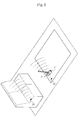
- the RFID reader 11 receives an RF signal transmitted from the RFID tag 30 attached to each object or surface to be cleaned, such as the carpet or sofa. In this way, the vacuum cleaner identifies the surface or object to be cleaned.
- a cleaning process of the vacuum cleaner of a first embodiment of the present invention will now be described with reference to Figure 4.
- operation 40 it is determined whether the automatic cleaning or the manual cleaning is to be performed. If it is determined that the manual cleaning is to be performed, the cleaning is performed with the cleaning capacity of the cleaner (i.e. suction force of the vacuum cleaner) as set by the user's manipulation of the control switch 15 (operation 52).
- the cleaning capacity of the cleaner i.e. suction force of the vacuum cleaner
- the RFID reader 11 transmits an RF signal to the interior of a room to identify an object to be cleaned (operation 42) and receives another RF signal that the RFID tag 30 transmits in respect to the RF signal transmitted from the RFID reader 11 (operation 44).
- the RFID reader 11 converts the RF signal received from the RFID tag 30 into a digital signal and then performs cycle redundancy check (CRC) to determine whether normal object identification data has been transmitted. If it is determined that the normal object identification data has been transmitted, the data is transmitted to the microcomputer 25.
- the normal object identification data is a certification number assigned to each RFID tag 30.
- the microcomputer 25 interprets the received object identification data to identify the kind of object or surface to be cleaned (operation 46).
- the microcomputer 25 stores certification numbers corresponding to the respective surfaces/objects to be cleaned. For example, information indicating that the surface/object to be cleaned is a carpet could be certification numbers 001 ⁇ 010 and the information indicating that the surface/object to be cleaned is a floor covered with laminated paper could be certification numbers 011 ⁇ 020.
- the microcomputer 25 After the kind of the surface/object to be cleaned is identified, the microcomputer 25 performs cleaning in the cleaning mode accordingly with reference to Table 1 of the control information storage unit 26 (operation 48). Then it is determined whether the cleaning has been finished (operation 50). If the cleaning has not yet finished, operation 42 is repeated.
- a vacuum cleaner according to a second embodiment of the present invention is shown in Figures 5 to 7 which uses a bar code 31 instead of the RFID tag 30 used in the first embodiment, as a surface/object identification means to identify a surface/object to be cleaned.
- the bar code 31 is attached to each surface or object to be cleaned and a bar code reader 16 is mounted to the bottom of the suction unit 10.
- the bar code reader 16 reads the bar code 31 to identify the surface/object to be cleaned.
- Other components of the vacuum cleaner according to the second embodiment correspond to those of the vacuum cleaner according to the first embodiment and therefore a detailed description thereof is omitted.
- the bar code reader 16 reads the bar code 31 which is the surface/object identification data (operation 62) and transmits the read bar code information to the microcomputer 25.
- the microcomputer 25 interprets the received bar code information to identify the kind of surface/object to be cleaned (operation 64).
- the microcomputer 25 stores bar code information corresponding to different types of surface/objects to be cleaned. For example, three bits of storage spaces may be assigned to indicate kinds of objects to be cleaned.
- the microcomputer 25 stores information indicating that the surface/object to be cleaned is a carpet when the received bar code information is 001 ⁇ 010 and the surface/object to be cleaned is a floor covered with laminated paper when the received bar code information is 011 ⁇ 101.
- Operation 66 and operation 68 of Figure 8 respectively correspond to operation 48 and operation 50 of Figure 4.
- Figure 9 is a view showing an automatic robot cleaner according to a third embodiment of the present invention.
- the automatic robot cleaner includes a cleaner body 80, a roller caster 82 and wheels 81 mounted to the bottom of the cleaner body 80 for enabling the cleaner body 80 to move.
- a dust suction port 83 and an RFID reader 84 are mounted to the bottom of the cleaner body 80.
- Reception of an RF signal from an RFID tag 85 and identification of kinds of surfaces/objects to be cleaned according to the third embodiment are identical to those of the first embodiment except that the third embodiment is applied to an automatic robot cleaner, not a manual cleaner.
- the third embodiment not only revolutions per minute of the fan motor but also the moving speed of the robot cleaner are changed based on the cleaning modes to control the cleaning capacity of the cleaner.
- the robot cleaner is controlled so that the moving speed of the robot cleaner in a carpet mode is lower than that of the robot cleaner in a laminated paper covered floor mode.
- the RFID reader 84 is mounted to the bottom of the cleaner body 80 of the automatic robot cleaner, although alternatively, a bar code reader may be mounted to the bottom of the cleaner body 80 for reading a bar code attached to the surface/object to be cleaned to perform automatic cleaning. Reading of a bar code by the bar code reader and identification of kinds of surfaces/objects to be cleaned according to the third embodiment are identical to those of the second embodiment.
- cleaning is performed based on cleaning modes individually set for specific types of surfaces/objects to be cleaned.
Landscapes
- Engineering & Computer Science (AREA)
- Mechanical Engineering (AREA)
- Electric Vacuum Cleaner (AREA)
Abstract
Description
- The present invention relates to a vacuum cleaner operable in a plurality of cleaning modes and a method of using the same.
- Vacuum cleaners are known the art and one such device is on the market. One is disclosed in Korean Unexamined Patent Publication No. 2003-0056826 comprising a cleaner body having a suction fan, a fan motor to drive the fan and a cyclonic dust collection unit. A suction unit is connected to the cleaner body to collect debris when a cleaning operation is performed.
- An extension pipe and a grip is connected to the suction unit to the upper end of the extension pipe and to one end of the suction hose. The other end of the suction hose is connected to the cleaner body. A control switch is disposed at one side of the grip to turn the cleaner on/off and control a suction force of the cleaner.
- When the control switch is operated to turn on the vacuum cleaner, dirt and debris is sucked, together with air, through the suction unit and is then transmitted to the cyclonic dust collection unit where the dust is separated from the air according to the principle of cyclone. The separated matter is collected into a dust collection bag in the cleaner body.
- The control switch can be manually operated to increase the suction force of the cleaner which may be required when, for example, a relatively large amount of dirt is present or when cleaning a surface from which it is difficult to remove foreign matter, such as a carpet. In this way, the cleaning capacity of the cleaner is increased. When a relatively small amount of debris is present, or when the surface to be cleaned is easy to remove foreign matter from, the control switch may be manipulated to decrease a suction force of the cleaner thereby decreasing the cleaning capacity of the cleaner.
- In such known vacuum cleaners, the control switch must be manually manipulated to control the cleaning capacity of the cleaner depending upon an object to be cleaned or the place where a cleaning operation is performed, which can be very troublesome and inconvenient. Furthermore, it is difficult for a user to set cleaning capacity to the appropriate level for every object to be cleaned, which may result in poor cleaning performance. This problem is even more serious in the case of automatic robot cleaners, in which a cleaning operation is performed based on a specified cleaning mode irrespective of a type of surface to be cleaned, and therefore, appropriate cleaning is not accomplished. For example, an automatic robot cleaner would perform a cleaning operation in the same cleaning mode irrespective of whether to clean a floor covered with laminated paper or floor control with carpet, even through the carpeted floor is more difficult to clean than the floor covered with laminated paper. As a result, for example, a flat smooth floor such as a laminated floor may be well cleaned while a carpeted floor may be poorly cleaned.
- Therefore, it is an aspect of the invention to provide a cleaner and a cleaning method using the same that is capable of performing appropriate cleaning based on an object to be cleaned.
- The present invention is therefore characterised by detection means to detect data relating to a type of surface to be cleaned from a surface identifier on said surface and a control means for selecting a cleaning mode for the surface to be cleaned dependent upon the detected data.
- In a preferred embodiment, the detection means comprises a radio frequency identification reader operable to read data in an identifying radio frequency transmitted by the surface identifier in the form of a radio frequency identifier tag. However, in an alternative preferred embodiment, the detection means comprises a bar code reader operable to read data from the surface identifier in the form of a bar code.
- Preferably, the control means includes a control information storage unit containing data relating to each cleaning mode and, a microprocessor, the detection means and control information storage unit being connected to the microprocessor to select the cleaning mode of the vacuum cleaner.
- A preferred embodiment comprises a suction fan to provide the suction force of the vacuum cleaner, each cleaning mode corresponding to a different suction fan speed and thereby to a different suction force.
- In another preferred embodiment, the vacuum cleaner is an automated self-propelled vacuum cleaner and each cleaning mode corresponds to a different speed of propulsion of the vacuum cleaner.
- The method of cleaning using a vacuum cleaner is characterised by the steps of detecting data relating to a type of surface to be cleaned from a surface identifier on said surface and selecting a cleaning mode for the surface to be cleaned dependent upon the detected data.
- According to another aspect of the present invention, there is provided a cleaner having a plurality of cleaning modes, including a reader reading object identification data stored in an object identification medium attached to an object to be cleaned, and a control unit interpreting the object identification data read by the reader to identify a kind of the object to be cleaned and controlling the cleaner such that the cleaner performs cleaning in a cleaning mode corresponding to the identified kind of the object to be cleaned.
- According to another aspect of the present invention, there is provided a cleaner including a radio frequency identification (RFID) reader transmitting an RF signal to an RFID tag attached to an object to be cleaned, the RFID tag having a certification number and receiving another RF signal transmitted from the RFID tag and a control unit interpreting the RF signal received from the RFID reader to identify a kind of the object to be cleaned and controlling the cleaner such that the cleaner performs cleaning in a cleaning mode corresponding to the identified kind of the object to be cleaned.
- According to another aspect of the present invention, there is provided a cleaning method including reading object identification data stored in an object identification medium and regarding an object to be cleaned, interpreting read the object identification data to identify a kind of the object to be cleaned, and controlling the cleaner to perform cleaning in a cleaning mode corresponding to the identified kind of the object to be cleaned.
- According to another aspect of the present invention, there is provided a vacuum cleaning system including an object type provider providing a type of an object to be cleaned, a reading section reading the type of the object to be cleaned, and a control section selecting one of plural cleaning modes based on the read type of the object to be cleaned and causing a vacuum cleaner to clean the object to be cleaned in the selected cleaning mode.
- A preferred embodiment of the present invention will now be described, by way of example only, with reference to the accompanying drawings, in which:
- Figure 1 is a view showing a vacuum cleaner according to a first embodiment of the present invention;
- Figure 2 is a block diagram showing the construction of the vacuum cleaner shown in Figure 1;
- Figure 3 is a view illustrating how an object to be cleaned is identified by the vacuum cleaner shown in Figures 1 and 2;
- Figure 4 is a flow chart illustrating a cleaning process of the vacuum cleaner shown in Figures 1 and 2;
- Figure 5 is a view showing a vacuum cleaner according to a second embodiment of the present invention;
- Figure 6 is a block diagram showing the construction of the vacuum cleaner shown in Figure 5;
- Figure 7 is a view illustrating how an object to be cleaned is identified by the vacuum cleaner shown in Figures 5 and 6;
- Figure 8 is a flow chart illustrating a cleaning process of the vacuum cleaner shown in Figures 5 and 6; and
- Figure 9 is a view showing an automatic robot cleaner according to a third embodiment of the present invention.
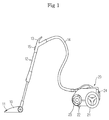
- Referring to Figure 1, a vacuum cleaner is shown comprising a
suction unit 10 to pick up debris during a cleaning operation and acleaner body 20 connected to thesuction unit 10 by a plurality of connection members. Thesuction unit 10 has a radio frequency identification (RFID) reader 11 which transmits a radio frequency (RF) signal to the interior of a room and receives another RF signal from an RFID tag 30 (shown in Figures 2 and 3) mounted to an object to be cleaned, such as a carpet, a laminate floor, or a wooden floor, transmitted in response to the RF signal transmitted to the interior of the room. While the RFID reader is shown to be on thesuction unit 10 it is to be understood, however, that the RFID reader 11 may be mounted to other parts of the vacuum cleaner. - A fan (not shown) is mounted in the
cleaner body 20 to suck air containing dust and debris, a fan motor 27 (Figures 2 and 7) to drive the fan, and a dust collection unit (not shown) to separate foreign matter from air.Wheels 21 are attached to both sides of thecleaner body 20 to enable thecleaner body 20 to move. - A
roller caster 22 is mounted to the bottom of thecleaner body 20 to enable thecleaner body 20 to rotate right and left as it moves back and forth. Aventilation filter 23 is attached to one side of thecleaner body 20 adjacent to the front of thecleaner body 20, to filter air that has been separated from foreign matter and discharge the air to outside thecleaner body 20. - The plurality of connection members include an
extension pipe 12 connected to thesuction unit 10, and anextension hose 14 connected to thecleaner body 20. Theextension pipe 12 and theextension hose 14 are connected to each other via agrip 13. At one side of thegrip 13 is disposed acontrol switch 15 to turn the cleaner on/off and control a suction force of the cleaner. - Referring to the block diagram of Figure 2, the vacuum cleaner also includes a control
information storage unit 26 to store control information comprising a plurality of different cleaning modes corresponding to different surfaces to be cleaned and driving levels of the components of the cleaner. The vacuum cleaner also includes amicrocomputer 25 to control operation of the cleaner and aselection button 28 to allow a user to select automatic cleaning or manual cleaning. When the automatic cleaning is selected, the cleaning modes of the cleaner are automatically changed based on the type of surface to be cleaned. When the manual cleaning is selected, the cleaning capacity of the cleaner is controlled by the user through manipulation of thecontrol switch 15 of Figure 1. - The control
information storage unit 26 contains driving levels of components of the cleaner that are set based on the cleaning modes as indicated in Table 1. In this embodiment, only revolutions per minute of thefan motor 27 is set, although the driving levels of the other component may be set based on the cleaning modes.Table 1 Kinds of objects to be cleaned Cleaning modes Revolutions per minute of fan motor Floor covered with laminated paper Laminated paper covered floor mode A Carpet Carpet mode 1.5A Sofa Sofa Mode 1.2A fan motor 27 is A (where, A is constant) for the laminated covered floor mode because foreign matter such as dirt and debris is easily removed from laminate floors. In the carpet mode, the revolutions per minute of thefan motor 27 are increased to 1.5A because foreign matter is more difficult to remove from carpets than from a floor covered with laminated paper. Therefore, the suction force of the vacuum cleaner is increased to perform cleaning appropriate to each object or surface to be cleaned. - Referring to Figure 3, the RFID reader 11 receives an RF signal transmitted from the
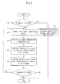
RFID tag 30 attached to each object or surface to be cleaned, such as the carpet or sofa. In this way, the vacuum cleaner identifies the surface or object to be cleaned. - A cleaning process of the vacuum cleaner of a first embodiment of the present invention will now be described with reference to Figure 4. When cleaning is started, it is determined whether the automatic cleaning or the manual cleaning is to be performed (operation 40). If it is determined that the manual cleaning is to be performed, the cleaning is performed with the cleaning capacity of the cleaner (i.e. suction force of the vacuum cleaner) as set by the user's manipulation of the control switch 15 (operation 52).
- Alternatively, if it is determined that automatic cleaning is to be performed, the RFID reader 11 transmits an RF signal to the interior of a room to identify an object to be cleaned (operation 42) and receives another RF signal that the
RFID tag 30 transmits in respect to the RF signal transmitted from the RFID reader 11 (operation 44). - The RFID reader 11 converts the RF signal received from the
RFID tag 30 into a digital signal and then performs cycle redundancy check (CRC) to determine whether normal object identification data has been transmitted. If it is determined that the normal object identification data has been transmitted, the data is transmitted to themicrocomputer 25. The normal object identification data is a certification number assigned to eachRFID tag 30. - The
microcomputer 25 interprets the received object identification data to identify the kind of object or surface to be cleaned (operation 46). Themicrocomputer 25 stores certification numbers corresponding to the respective surfaces/objects to be cleaned. For example, information indicating that the surface/object to be cleaned is a carpet could be certification numbers 001~010 and the information indicating that the surface/object to be cleaned is a floor covered with laminated paper could be certification numbers 011~020. - After the kind of the surface/object to be cleaned is identified, the
microcomputer 25 performs cleaning in the cleaning mode accordingly with reference to Table 1 of the control information storage unit 26 (operation 48). Then it is determined whether the cleaning has been finished (operation 50). If the cleaning has not yet finished,operation 42 is repeated. - A vacuum cleaner according to a second embodiment of the present invention is shown in Figures 5 to 7 which uses a
bar code 31 instead of theRFID tag 30 used in the first embodiment, as a surface/object identification means to identify a surface/object to be cleaned. - In the second embodiment, the
bar code 31 is attached to each surface or object to be cleaned and abar code reader 16 is mounted to the bottom of thesuction unit 10. Thebar code reader 16 reads thebar code 31 to identify the surface/object to be cleaned. Other components of the vacuum cleaner according to the second embodiment correspond to those of the vacuum cleaner according to the first embodiment and therefore a detailed description thereof is omitted. - A cleaning process using the vacuum cleaner according to the second embodiment of the present invention will now be described with reference to Figure 8.
- When cleaning is started, it is determined whether automatic cleaning or manual cleaning is to be performed (operation 60). If it is determined that manual cleaning is to be performed, the cleaning is performed with the cleaning capacity of the cleaner (i.e. suction force of the vacuum cleaner) as set through by user's manipulation of a control switch (operation 70).
- If it is determined that automatic cleaning is to be performed, the
bar code reader 16 reads thebar code 31 which is the surface/object identification data (operation 62) and transmits the read bar code information to themicrocomputer 25. - The
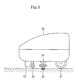
microcomputer 25 interprets the received bar code information to identify the kind of surface/object to be cleaned (operation 64). Themicrocomputer 25 stores bar code information corresponding to different types of surface/objects to be cleaned. For example, three bits of storage spaces may be assigned to indicate kinds of objects to be cleaned. Themicrocomputer 25 stores information indicating that the surface/object to be cleaned is a carpet when the received bar code information is 001~010 and the surface/object to be cleaned is a floor covered with laminated paper when the received bar code information is 011~101. Operation 66 andoperation 68 of Figure 8 respectively correspond tooperation 48 andoperation 50 of Figure 4. - Figure 9 is a view showing an automatic robot cleaner according to a third embodiment of the present invention. As shown in Figure 9, the automatic robot cleaner includes a
cleaner body 80, aroller caster 82 andwheels 81 mounted to the bottom of thecleaner body 80 for enabling thecleaner body 80 to move. Adust suction port 83 and anRFID reader 84 are mounted to the bottom of thecleaner body 80. - Reception of an RF signal from an
RFID tag 85 and identification of kinds of surfaces/objects to be cleaned according to the third embodiment are identical to those of the first embodiment except that the third embodiment is applied to an automatic robot cleaner, not a manual cleaner. In the third embodiment, not only revolutions per minute of the fan motor but also the moving speed of the robot cleaner are changed based on the cleaning modes to control the cleaning capacity of the cleaner. For example, the robot cleaner is controlled so that the moving speed of the robot cleaner in a carpet mode is lower than that of the robot cleaner in a laminated paper covered floor mode. - In the third embodiment, the
RFID reader 84 is mounted to the bottom of thecleaner body 80 of the automatic robot cleaner, although alternatively, a bar code reader may be mounted to the bottom of thecleaner body 80 for reading a bar code attached to the surface/object to be cleaned to perform automatic cleaning. Reading of a bar code by the bar code reader and identification of kinds of surfaces/objects to be cleaned according to the third embodiment are identical to those of the second embodiment. - As is apparent from the above description, cleaning is performed based on cleaning modes individually set for specific types of surfaces/objects to be cleaned.
- Consequently, the above described embodiments of the present invention efficiently perform cleaning irrespective of kinds of surfaces/objects to be cleaned.
- Although a few embodiments of the present invention have been shown and described, the present invention is not limited to the described embodiments and changes may be made to these embodiments without departing from the principles of the invention, the scope of which is defined by the claims hereafter.
Claims (21)
- A vacuum cleaner operable in a plurality of cleaning modes characterised by detection means to detect data relating to a type of surface to be cleaned from a surface identifier on said surface and a control means for selecting a cleaning mode for the surface to be cleaned dependent upon the detected data.
- A vacuum cleaner according to claim 1 wherein the detection means comprises a radio frequency identification reader operable to read data in an identifying radio frequency transmitted by the surface identifier in the form of a radio frequency identifier tag.
- A vacuum cleaner according to claim 1 wherein the detection means comprises a bar code reader operable to read data from the surface identifier in the form of a bar code.
- A vacuum cleaner according to any of claims 1 to 3 wherein the control means includes a control information storage unit containing data relating to each cleaning mode and a microcompressor, the detection means and control information storage unit being connected to the microcompressor to select the cleaning mode of the vacuum cleaner.
- A vacuum cleaner according to any preceding claim comprising a suction fan to provide the suction force of the vacuum cleaner, each cleaning mode corresponding to a different suction fan speed and thereby to a different suction force.
- A vacuum cleaner according to any preceding claim wherein the vacuum cleaner is an automated self-propelled vacuum cleaner and each cleaning mode corresponds to a different speed of propulsion of the vacuum cleaner.
- A method of cleaning using a vacuum cleaner comprising a detecting means and a control means, operable in a plurality of cleaning modes characterised by the steps of detecting data relating to a type of surface to be cleaned from a surface identifier on said surface and selecting a cleaning mode for the surface to be cleaned dependent upon the detected data.
- A cleaning having a plurality of cleaning modes comprising a reader reading object identification data stored in an object identification medium attached to an object to be cleaned and a control unit interpreting the object identification data read by the reader to identify a kind of object to be cleaned and controlling the cleaner such that the cleaner performs cleaning in a cleaning mode corresponding to the identified kind of object to be cleaned.
- The cleaner according to claim 8 further comprising a fan generating a suction force wherein revolutions per minute of the fan differ among the cleaning modes so as to generate different suction forces in the cleaning modes.
- The cleaner according to claim 8 further comprising a control information storage unit storing control information including driving levels of components of the cleaner based on the cleaning modes.
- The cleaner according to claim 8 wherein the object identification medium is a radio frequency identification (RFID) tag and the reader is an RFID reader receiving object identification data transmitted from the RFID tag.
- The cleaner according to claim 8 wherein the object identification medium is a bar code and the reader is a bar code reader reading a bar code containing object identification data.
- A cleaner comprising a radio frequency identification (RFID) reader transmitting an RF signal to an RFID tag attached to an object to be cleaned, the RFID tag having a certification number and receiving another RF signal transmitted from the RFID tag and a control unit interpreting the RF signal received from the RFID reader to identify a kind of object to be cleaned and controlling the cleaner such that the cleaner performs cleaning in a cleaning mode corresponding to the identified kind of object to be cleaned.
- The cleaner according to claim 13 further comprising a control information storage unit storing control information including driving levels of components of the cleaner based on a plurality of cleaning modes.
- A cleaning method comprising reading object identification data stored in an object identification medium and regarding an object to be cleaned, interpreting read the object identification data to identify a kind of object to be cleaned and controlling the cleaner to perform cleaning in a cleaning mode corresponding to the identified kind of object to be cleaned.
- The method according to claim 15 wherein the object identification medium is an RFID tag having a certification number and the reading is performed by a radio frequency identification (RFID) reader receiving object identification data transmitted from the RFID tag.
- The method according to claim 16 wherein the object identification medium is a bar code and the reader is a bar code reader reading a bar code containing object identification data.
- The vacuum cleaner according to claim 16 wherein the RFID tag transmits an RFID signal in response to a received RFID request signal from the RFID reader.
- The method according to claim 15 wherein the object identification medium is attached to the object.
- The vacuum cleaner according to claim 15 wherein the object is an item of furniture or a surface.
- A vacuum cleaning system comprising an object type provided providing a type of an object to be cleaned, a reading section reading the type of object to be cleaned and a control section selecting one of plural cleaning modes based on the read type of the object to be cleaned and causing a vacuum cleaner to clean the object to be cleaned in the selected cleaning mode.
Applications Claiming Priority (1)
| Application Number | Priority Date | Filing Date | Title |
|---|---|---|---|
| KR1020040071896A KR20060023068A (en) | 2004-09-08 | 2004-09-08 | Cleaner and cleaning method using the same |
Publications (2)
| Publication Number | Publication Date |
|---|---|
| EP1639934A2 true EP1639934A2 (en) | 2006-03-29 |
| EP1639934A3 EP1639934A3 (en) | 2007-11-07 |
Family
ID=36165533
Family Applications (1)
| Application Number | Title | Priority Date | Filing Date |
|---|---|---|---|
| EP05106262A Withdrawn EP1639934A3 (en) | 2004-09-08 | 2005-07-08 | Vacuum cleaner |
Country Status (4)
| Country | Link |
|---|---|
| US (1) | US20060048797A1 (en) |
| EP (1) | EP1639934A3 (en) |
| KR (1) | KR20060023068A (en) |
| CN (1) | CN1745693A (en) |
Cited By (2)
| Publication number | Priority date | Publication date | Assignee | Title |
|---|---|---|---|---|
| EP1898289A3 (en) * | 2006-09-02 | 2008-08-13 | InMach Intelligente Maschinen GmbH | Modular system for providing an infrastructure to control a surface machining device |
| EP2505112A1 (en) | 2011-03-29 | 2012-10-03 | Seb S.A. | Vacuum cleaner with means for detecting the presence of a nozzle |
Families Citing this family (30)
| Publication number | Priority date | Publication date | Assignee | Title |
|---|---|---|---|---|
| US7086111B2 (en) * | 2001-03-16 | 2006-08-08 | Braun Gmbh | Electric dental cleaning device |
| US7464510B2 (en) | 2000-09-19 | 2008-12-16 | Interface, Inc. | System and method for floor covering installation |
| DE10159395B4 (en) * | 2001-12-04 | 2010-11-11 | Braun Gmbh | Device for cleaning teeth |
| WO2002071970A1 (en) | 2001-03-14 | 2002-09-19 | Braun Gmbh | Method and device for cleaning teeth |
| US8443476B2 (en) | 2001-12-04 | 2013-05-21 | Braun Gmbh | Dental cleaning device |
| US8468772B2 (en) | 2003-08-11 | 2013-06-25 | Interface, Inc. | Carpet tiles and carpet tile installations |
| DE102004062150A1 (en) * | 2004-12-23 | 2006-07-13 | Braun Gmbh | Interchangeable accessory for a small electrical appliance and method for determining the service life of the accessory |
| KR100867896B1 (en) * | 2007-01-18 | 2008-11-10 | 주식회사 우리기술 | Robot cleaning building exterior walls and windows. |
| US8524010B2 (en) * | 2007-03-07 | 2013-09-03 | Ecoservices, Llc | Transportable integrated wash unit |
| EP2554616A3 (en) | 2007-03-27 | 2013-06-26 | Interface, Inc. | System and method for floor covering installation |
| DE102007022827A1 (en) * | 2007-05-15 | 2008-11-20 | Braun Gmbh | Toothbrush attachment and method for its production |
| DE102007029973A1 (en) * | 2007-06-28 | 2009-01-08 | Braun Gmbh | toothbrush |
| US20090267741A1 (en) * | 2008-04-25 | 2009-10-29 | Eric Chun-Yip Li | RFID Floor Tags for Machine Localization and Delivery of Visual Information |
| US20100114372A1 (en) * | 2008-10-30 | 2010-05-06 | Intellibot Robotics Llc | Method of cleaning a surface using an automatic cleaning device |
| US20100251641A1 (en) * | 2009-04-07 | 2010-10-07 | Interface, Inc. | Systems and Methods for Modular Floor Installation |
| EP2420203B1 (en) | 2010-08-19 | 2019-10-23 | Braun GmbH | Resonant motor unit and electric device with resonant motor unit |
| DK2705192T3 (en) | 2011-05-04 | 2015-05-18 | Tandus Flooring Inc | Modular carpet system |
| US9443357B2 (en) | 2011-07-11 | 2016-09-13 | Gojo Industries, Inc. | Dispenser use monitor |
| EP2550938B1 (en) | 2011-07-25 | 2015-01-14 | Braun GmbH | Oral hygiene device |
| PL2550937T3 (en) | 2011-07-25 | 2014-07-31 | Braun Gmbh | Magnetic connection between a toothbrush handle and a brush head |
| ES2646447T3 (en) | 2011-07-25 | 2017-12-13 | Braun Gmbh | Oral care devices with linear electro-polymer motors |
| CN103324191A (en) * | 2012-03-23 | 2013-09-25 | 苏州宝时得电动工具有限公司 | Control method and control system executing same |
| KR101893152B1 (en) * | 2012-10-26 | 2018-08-31 | 엘지전자 주식회사 | robot cleaner system and a control method of the same |
| US9675226B2 (en) | 2012-10-26 | 2017-06-13 | Lg Electronics Inc. | Robot cleaner system and control method of the same |
| WO2016118797A1 (en) | 2015-01-22 | 2016-07-28 | Interface, Inc. | Floor covering system with sensors |
| US9868211B2 (en) | 2015-04-09 | 2018-01-16 | Irobot Corporation | Restricting movement of a mobile robot |
| WO2019143700A1 (en) | 2018-01-17 | 2019-07-25 | Tti (Macao Commercial Offshore) Limited | System and method for operating a cleaning system based on a surface to be cleaned |
| CN108803600A (en) * | 2018-05-31 | 2018-11-13 | 北京智行者科技有限公司 | A method of executing cleaning work |
| CN111282937A (en) * | 2020-03-27 | 2020-06-16 | 江苏乐橘云盘科技有限公司 | A tray cleaning, drying and sorting line |
| CN118847619A (en) * | 2024-08-07 | 2024-10-29 | 湖北亿纬动力有限公司 | A rolling roller cleaning system and a cleaning method thereof |
Family Cites Families (9)
| Publication number | Priority date | Publication date | Assignee | Title |
|---|---|---|---|---|
| US5086535A (en) * | 1990-10-22 | 1992-02-11 | Racine Industries, Inc. | Machine and method using graphic data for treating a surface |
| US5279672A (en) * | 1992-06-29 | 1994-01-18 | Windsor Industries, Inc. | Automatic controlled cleaning machine |
| FR2708188A1 (en) * | 1993-07-28 | 1995-02-03 | Philips Laboratoire Electroniq | Vacuum cleaner with means of soil detection and adjustment of the engine power according to the detected soil. |
| IT1271241B (en) * | 1994-10-04 | 1997-05-27 | Consorzio Telerobot | NAVIGATION SYSTEM FOR AUTONOMOUS MOBILE ROBOT |
| GB2344888A (en) * | 1998-12-18 | 2000-06-21 | Notetry Ltd | Obstacle detection system |
| KR100342029B1 (en) * | 1999-06-07 | 2002-06-27 | 탁승호 | Surface-travelling mobile apparatus and cleaning apparatus using the same |
| US6608551B1 (en) * | 1999-09-13 | 2003-08-19 | Intermec Ip Corp | Low-cost radio replacement utilizing RFID technology |
| EP1136027B1 (en) * | 2000-03-17 | 2008-07-09 | Vorwerk & Co. Interholding GmbH | Floor treating apparatus and method for recognizing a state of floor respectively for aligning the drive movement |
| DE10346216B3 (en) * | 2003-09-24 | 2004-09-09 | Alfred Kärcher Gmbh & Co. Kg | Mobile cleaning machine for cleaning floor of rooms has drive wheels and brush and has CCD camera and may sense markers set at edges of doorways |
-
2004
- 2004-09-08 KR KR1020040071896A patent/KR20060023068A/en not_active Withdrawn
-
2005
- 2005-07-01 US US11/171,258 patent/US20060048797A1/en not_active Abandoned
- 2005-07-05 CN CNA2005100824981A patent/CN1745693A/en active Pending
- 2005-07-08 EP EP05106262A patent/EP1639934A3/en not_active Withdrawn
Cited By (2)
| Publication number | Priority date | Publication date | Assignee | Title |
|---|---|---|---|---|
| EP1898289A3 (en) * | 2006-09-02 | 2008-08-13 | InMach Intelligente Maschinen GmbH | Modular system for providing an infrastructure to control a surface machining device |
| EP2505112A1 (en) | 2011-03-29 | 2012-10-03 | Seb S.A. | Vacuum cleaner with means for detecting the presence of a nozzle |
Also Published As
| Publication number | Publication date |
|---|---|
| US20060048797A1 (en) | 2006-03-09 |
| EP1639934A3 (en) | 2007-11-07 |
| CN1745693A (en) | 2006-03-15 |
| KR20060023068A (en) | 2006-03-13 |
Similar Documents
| Publication | Publication Date | Title |
|---|---|---|
| EP1639934A2 (en) | Vacuum cleaner | |
| AU2003259634B2 (en) | Robot Cleaner | |
| TWI769413B (en) | Method for controlling a robot cleaner | |
| JP4181477B2 (en) | Self-propelled vacuum cleaner | |
| AU761745B2 (en) | Robotic floor cleaning device | |
| EP1752077B1 (en) | Robot cleaner having function for detecting separation of dust tank and control method thereof | |
| CN115175599B (en) | Mobile cleaning robot hardware recommendation | |
| US20040177467A1 (en) | Automated electronic vacuum system and method | |
| JP2005040576A (en) | Robot cleaner with air cleaning function and system thereof | |
| US11397437B2 (en) | System with a first floor processing device and a second floor processing device as well as a method for operating such a system | |
| AU2004237819A1 (en) | Robot Cleaner | |
| JP2005211365A (en) | Autonomous traveling robot cleaner | |
| EP3589181A1 (en) | Vacuum cleaner and vacuum cleaning system in wireless communication with a user-controlled electronic device | |
| EP4059402B1 (en) | Floor types identifying device, dust suction device having the same, and vacuum cleaner having the same | |
| GB2486977A (en) | Suction nozzle with an edge brush and obstacle sensor | |
| KR20160031836A (en) | Vacuum cleaner, contorl method thereof and computer readable recording media | |
| CN106725099A (en) | Combined dust collector | |
| KR20210022359A (en) | cleaner and controling method the cleaner | |
| CN103476314A (en) | Electric vacuum cleaner | |
| JP2020146457A (en) | Floor processing device and system comprised of floor processing device and external terminal | |
| JP4876986B2 (en) | Vacuum cleaner | |
| JP4654794B2 (en) | Electric vacuum cleaner | |
| JP2009000372A (en) | Self-propelled vacuum cleaner | |
| JP2011193897A (en) | Vacuum cleaner | |
| US20230255424A1 (en) | Robot cleaner and method for controlling same |
Legal Events
| Date | Code | Title | Description |
|---|---|---|---|
| PUAI | Public reference made under article 153(3) epc to a published international application that has entered the european phase |
Free format text: ORIGINAL CODE: 0009012 |
|
| AK | Designated contracting states |
Kind code of ref document: A2 Designated state(s): AT BE BG CH CY CZ DE DK EE ES FI FR GB GR HU IE IS IT LI LT LU LV MC NL PL PT RO SE SI SK TR |
|
| AX | Request for extension of the european patent |
Extension state: AL BA HR MK YU |
|
| PUAL | Search report despatched |
Free format text: ORIGINAL CODE: 0009013 |
|
| AK | Designated contracting states |
Kind code of ref document: A3 Designated state(s): AT BE BG CH CY CZ DE DK EE ES FI FR GB GR HU IE IS IT LI LT LU LV MC NL PL PT RO SE SI SK TR |
|
| AX | Request for extension of the european patent |
Extension state: AL BA HR MK YU |
|
| STAA | Information on the status of an ep patent application or granted ep patent |
Free format text: STATUS: THE APPLICATION IS DEEMED TO BE WITHDRAWN |
|
| AKX | Designation fees paid | ||
| 18D | Application deemed to be withdrawn |
Effective date: 20080201 |
|
| REG | Reference to a national code |
Ref country code: DE Ref legal event code: 8566 |