EP1637808A2 - Gas hob with electronic control system - Google Patents
Gas hob with electronic control system Download PDFInfo
- Publication number
- EP1637808A2 EP1637808A2 EP05108211A EP05108211A EP1637808A2 EP 1637808 A2 EP1637808 A2 EP 1637808A2 EP 05108211 A EP05108211 A EP 05108211A EP 05108211 A EP05108211 A EP 05108211A EP 1637808 A2 EP1637808 A2 EP 1637808A2
- Authority
- EP
- European Patent Office
- Prior art keywords
- hob
- cooking
- timer
- cut
- gas
- Prior art date
- Legal status (The legal status is an assumption and is not a legal conclusion. Google has not performed a legal analysis and makes no representation as to the accuracy of the status listed.)
- Withdrawn
Links
- 238000010411 cooking Methods 0.000 claims abstract description 119
- 230000003287 optical effect Effects 0.000 claims description 2
- 238000001514 detection method Methods 0.000 description 15
- 235000013305 food Nutrition 0.000 description 6
- 238000010438 heat treatment Methods 0.000 description 6
- 238000000034 method Methods 0.000 description 5
- 230000008569 process Effects 0.000 description 5
- XLYOFNOQVPJJNP-UHFFFAOYSA-N water Substances O XLYOFNOQVPJJNP-UHFFFAOYSA-N 0.000 description 5
- 230000008901 benefit Effects 0.000 description 4
- 235000015927 pasta Nutrition 0.000 description 4
- 230000004913 activation Effects 0.000 description 3
- 238000009835 boiling Methods 0.000 description 3
- 238000010586 diagram Methods 0.000 description 3
- 238000002604 ultrasonography Methods 0.000 description 3
- 230000005540 biological transmission Effects 0.000 description 2
- 230000005662 electromechanics Effects 0.000 description 2
- 239000007788 liquid Substances 0.000 description 2
- 238000012545 processing Methods 0.000 description 2
- 230000009471 action Effects 0.000 description 1
- 238000013459 approach Methods 0.000 description 1
- 238000009529 body temperature measurement Methods 0.000 description 1
- 238000005520 cutting process Methods 0.000 description 1
- 230000001419 dependent effect Effects 0.000 description 1
- 238000013461 design Methods 0.000 description 1
- 238000009826 distribution Methods 0.000 description 1
- 238000005265 energy consumption Methods 0.000 description 1
- 238000004519 manufacturing process Methods 0.000 description 1
- 230000009467 reduction Effects 0.000 description 1
- 238000007789 sealing Methods 0.000 description 1
- 238000012360 testing method Methods 0.000 description 1
Images

Classifications
-
- F—MECHANICAL ENGINEERING; LIGHTING; HEATING; WEAPONS; BLASTING
- F24—HEATING; RANGES; VENTILATING
- F24C—DOMESTIC STOVES OR RANGES ; DETAILS OF DOMESTIC STOVES OR RANGES, OF GENERAL APPLICATION
- F24C3/00—Stoves or ranges for gaseous fuels
- F24C3/12—Arrangement or mounting of control or safety devices
- F24C3/126—Arrangement or mounting of control or safety devices on ranges
-
- F—MECHANICAL ENGINEERING; LIGHTING; HEATING; WEAPONS; BLASTING
- F23—COMBUSTION APPARATUS; COMBUSTION PROCESSES
- F23N—REGULATING OR CONTROLLING COMBUSTION
- F23N1/00—Regulating fuel supply
- F23N1/007—Regulating fuel supply using mechanical means
-
- F—MECHANICAL ENGINEERING; LIGHTING; HEATING; WEAPONS; BLASTING
- F23—COMBUSTION APPARATUS; COMBUSTION PROCESSES
- F23N—REGULATING OR CONTROLLING COMBUSTION
- F23N5/00—Systems for controlling combustion
- F23N5/02—Systems for controlling combustion using devices responsive to thermal changes or to thermal expansion of a medium
- F23N5/10—Systems for controlling combustion using devices responsive to thermal changes or to thermal expansion of a medium using thermocouples
- F23N5/102—Systems for controlling combustion using devices responsive to thermal changes or to thermal expansion of a medium using thermocouples using electronic means
-
- F—MECHANICAL ENGINEERING; LIGHTING; HEATING; WEAPONS; BLASTING
- F23—COMBUSTION APPARATUS; COMBUSTION PROCESSES
- F23N—REGULATING OR CONTROLLING COMBUSTION
- F23N2235/00—Valves, nozzles or pumps
- F23N2235/12—Fuel valves
- F23N2235/16—Fuel valves variable flow or proportional valves
-
- F—MECHANICAL ENGINEERING; LIGHTING; HEATING; WEAPONS; BLASTING
- F23—COMBUSTION APPARATUS; COMBUSTION PROCESSES
- F23N—REGULATING OR CONTROLLING COMBUSTION
- F23N2241/00—Applications
- F23N2241/08—Household apparatus
-
- F—MECHANICAL ENGINEERING; LIGHTING; HEATING; WEAPONS; BLASTING
- F23—COMBUSTION APPARATUS; COMBUSTION PROCESSES
- F23N—REGULATING OR CONTROLLING COMBUSTION
- F23N5/00—Systems for controlling combustion
- F23N5/24—Preventing development of abnormal or undesired conditions, i.e. safety arrangements
Definitions
- the present invention relates to a gas hob according to the preamble of claim 1.
- the present invention is typically applied to gas hobs for domestic use.
- Gas hobs for domestic use are generally equipped with a flat surface housing four or six cooking points. Each cooking point has at least one gas heating element, i.e. a burner, and at least one support element allowing to lay a cook-ware over the burner.
- gas heating element i.e. a burner
- support element allowing to lay a cook-ware over the burner.
- each cooking point corresponds to a single tap for adjusting the gas flow and thus the flame generated by the burner; the tap is associated with a knob which can be operated by the user during the adjustment.
- cooking points comprising two burners adapted to be adjusted by the user.
- each cooking point also corresponds to a valve which may be in two different operating conditions: a condition in which it is open and therefore allows gas to be supplied to the burner, and a condition in which it is closed and therefore prevents gas from being supplied to the burner; the opening/closing of this valve is usually controlled by a thermocouple detecting the temperature near the burner, so as to cut off the gas supply if there is no flame (i.e. when a low temperature is detected, e.g. lower than 200°C, taking into account that at the center of the flame there is a temperature of approx. 600°C), thus acting as a safety device.
- a thermocouple detecting the temperature near the burner, so as to cut off the gas supply if there is no flame (i.e. when a low temperature is detected, e.g. lower than 200°C, taking into account that at the center of the flame there is a temperature of approx. 600°C), thus acting as a safety device.
- timers for helping the user to obtain properly cooked food have been on the market for many years. Many years ago, such timers were merely mechanic; electromechanic timers appeared later, and nowadays electronic timers are widespread.
- the user manually sets a time corresponding to a desired cooking time (e.g. 10 minutes).
- a desired cooking time e.g. 10 minutes.
- the timer activates automatically.
- the timer determines that a time corresponding to the time set by the user has elapsed, it typically emits an audible signal.
- the user hears such a signal, he/she acts upon the hob and typically "turns off the cooker ", i.e. turns the adjustment knob of the tap corresponding to the cooking point where the cooking has to be stopped until the flame generated by the burner is turned off.
- Patent DE2909129 describes an electric hob fitted with a heating power control system; said hob is associated with a temperature sensor.
- the temperature sensor is located on the lid of a pot and is connected to an ultrasound emitter; the temperature detected by the sensor is transmitted to the hob, typically during a cooking phase, through the ultrasound emitter; the sensor and the emitter are powered by a battery.
- the control system can, among other things, adjust the electric power supplied to a heating source of the hob on the basis of the temperature detected by the sensor.
- Said Patent also provides for the use of a timer which may be connected to the transmitter and which may be set to a desired cooking time by the user, so that the control system can adjust the electric power supplied to the heating source of the hob and reduce it to zero when the set time has elapsed.
- Patent DE3225486 describes an electric hob being similar to the one previously described, but having a temperature sensor which does not need to be connected to a battery; in fact, the temperature sensor is powered by the hob control system thanks to the electromagnetic energy transmitted by an antenna.
- the object of the present invention is to provide a solution for gas hobs which is able to control the cooking process automatically and effectively and which is both simple and economical to implement.
- the idea at the basis of the present invention is to achieve cooking control through simple cut-off means.
- gas hobs are normally fitted with gas supply cut-off means, even if the latter are used solely as safety devices.
- Fig. 1 shows a gas hob for domestic use, indicated as a whole with reference number 1, having four cooking points, each being indicated with reference number 2; each cooking point 2 comprises at least one gas burner, indicated as a whole with reference number 21.
- One of the cooking points, shown in Fig. 3, comprises two gas burners, indicated with reference numbers 21A and 21B; more specifically, the burner 21B is divided into two parts which enclose the burner 21A.
- FIG. 2 The block diagram of Fig. 2 shows just one cooking point, i.e. the one of Fig. 3.
- knobs 9 corresponding to the number of gas burners of the four cooking points 2; in fact, one cooking point comprises two burners; each knob 9 allows the user to adjust the gas flow supplied to an associated burner.
- the hob 1 works on gas; the gas is supplied to the inlets of a number of safety valves, indicated as a whole with reference number 3, corresponding to the number of burners 21; Fig. 2 shows just two valves 3A and 3B, corresponding to the burners 21A and 21B of the only cooking point illustrated.
- the safety valves 3 are used to cut off the gas supply to the burners; each of these valves may be either open, thereby allowing gas to be supplied to the respective burner, or closed, thereby preventing gas from being supplied to the respective burner.
- the outlets of the safety valves 3 are connected to the respective burners through gas flow adjustment taps 10; the taps 10 are as many as the number of burners, and are actuated by the user through the respective knobs 9.
- the cooking point represented in Fig. 2 is fitted with a support element allowing the user to lay down the cook-ware over the two burners 3A and 3B.
- a pressure cooker has been laid down on the support element 8; said pressure cooker 8 has a detection system 5 being able to detect the temperature within the pressure cooker 8 and to transmit radio signals indicating the detected temperature values.
- Reference number 7 represents a timer being adjustable by the user.
- Reference number 4 represents a radio receiver.
- the hob 1 comprises an electronic control system 6; the system 6 is connected to the timer 7, the receiver 4 and the valves 3A and 3B; also, the system 6 is connected to two thermocouples (not shown in Fig. 2) being associated with the two burners 3A and 3B of the cooking point, respectively.
- Fig. 2 shows a partial block diagram of the hob of Fig. 1 and therefore, for example, shows neither any elements nor any connections related to the other three burners of the hob 1.
- the hob according to the present invention comprises at least one gas burner and cut-off means adapted to interrupt the gas supply to at least said burner; in the illustrated example, the cut-off means consist of the two safety valves 3A and 3B being associated with the two burners 21A and 21B.
- the hob according to the present invention also comprises:
- the reception means are typically of the electronic type; in the illustrated example, they consist of the radio receiver 4.
- the detection system transmitting signals to the reception means is typically external to the hob; in the illustrated example, it consists of the system 5.
- the detection system may be more or less complex; for instance, it may be adapted to operate autonomously and to detect and transmit the cooking parameter continuously or periodically; as an alternative, the detection system may be adapted to detect and transmit the cooking parameter only when interrogated by the electronic control system of the hob.
- the detection system may be active, i.e. supplied by an internal power source such as, for example, a battery - as described in the cited Patent DE2909129; alternately, the detection system may be passive, i.e. supplied by an external power source - as described in the cited Patent DE3225486. It is worth mentioning that detection systems adapted to cooperate with a hob according to the present invention are known at least in the patent literature, in particular in the above-mentioned Patents.
- the cooking parameter may be the temperature, the pressure or the humidity at which the cooking is taking place.
- the cooking parameters also include parameters being related to the "cooking time”, i.e.: “cooking time elapsed", “remaining cooking time” and a "end of cooking” indication, the latter being the most direct one.
- cooking parameters are adapted to be used with particular types of cook-ware; for instance, cooking pressure may be used when a pressure cooker is employed.
- the values of the parameter or the parameters are processed by the electronic control system of the hob. Sometimes this processing may be extremely simple; this is the case, for instance, when the cooking parameter corresponds to the "end of cooking" indication. It should be noted that the detection system may as well be adapted to perform an initial processing of the detected parameter values.
- cooking control is accomplished through simple cut-off means.
- gas hobs are normally fitted with gas supply cut-off means; advantageously, this control exploits said means for other useful functions.
- the reception means and the detection system are not connected through a cable; as a matter of fact, cables located near heat sources are easily subject to damage; moreover, cables near cooking points hinder the user's movements, preventing him/her to lay down and move the cook-ware with ease; in such a case, the reception means are adapted to receive optical signals (e.g. infrared signals), acoustic signals (e.g., ultrasound signals) or radio signals. Tests carried out have shown that infrared signals are most suited to kitchen use; besides, both infrared transmitters and infrared receivers are rather simple and cheap devices.
- optical signals e.g. infrared signals
- acoustic signals e.g., ultrasound signals
- the most typical cooking parameters which may be used in the present invention are cooking temperature and cooking pressure; moreover, these physical quantities can be detected through simple and cheap electronic devices; this is even more true for temperature.
- Cooking parameters such as cooking temperature and cooking pressure may be easily detected by a detection system being external but close to the hob, in particular close to the cooking point where the cooking takes place.
- the detection system is associated with a cook-ware and is applied, for example, to the bottom, to the sides or to the lid of said cook-ware.
- the cooking parameters related to "cooking time” may be detected easily through a timer.
- the timer may be located either in the hob or in a position being close to it, e.g. on the kitchen working top or table; the timer may also be integrated into other household appliances, e.g. an oven or a hood; it is apparent that the timer cannot be too far from the hob, because it must be easily set and activated when using the hob.
- the timer may be advantageous to provide the timer with transmission means adapted to transmit signals indicating a parameter related to the "cooking time" to reception means of the hob; if the timer is fitted with transmission means, it may be located anywhere.
- the timer may be more or less complex; for example, it may be adapted to operate autonomously, thus transmit the parameter related to the "cooking time” either continuously or periodically; alternately, the timer may be adapted to transmit the parameter related to the "cooking time” only when interrogated by the electronic control system of the hob.
- the timer may be active, i.e. supplied by an internal power source such as, for instance, a battery.
- Such an innovative timer may be used also in combination with cooking appliances being different from the one described herein, e.g. an electric hob.
- the cook-ware is a pressure cooker, i.e. a cooking container having a lid which ensures a hermetic sealing; the pressure cooker lid is fitted with a valve being calibrated for opening under the action of a predefined pressure; this calibration is typically carried out during the manufacture of the pressure cooker and is set based on the maximum pressure which may be reached within the cook-ware during the cooking phase.
- a temperature sensor which detects the temperature of the steam generated during the cooking and coming out of the valve when the pressure exceeds the calibration value. A temperature measurement thus allows to detect pressure variations within the cook-ware.
- the hob according to the present invention comprises cut-off means adapted to interrupt the gas supply.
- these means may advantageously be in just two operating conditions: an operating condition wherein gas is supplied, and an operating condition wherein gas is not supplied.
- Cut-off means having these characteristics may advantageously be produced through safety valves like those typically used in hobs; moreover, the same valves may be used to perform both the usual safety functions and the control functions according to the present invention.
- the hob according to the present invention may also comprise a timer, and its electronic control system may be adapted to control the cut-off means on the basis of signals sent by the timer; the cooking process may thus be controlled, for example, based both on cooking temperature or pressure and on cooking time.
- a timer may typically be set by the user, i.e. for the timer is adapted to count a time corresponding to the time interval, set by the user, being necessary to obtain properly cooked food; such a time interval may refer to the complete cooking of the food or just to a certain cooking phase.
- the electronic control system being present on the hob processes the values of the cooking parameter or parameters coming from the reception means and therefore from the detection system.
- the electronic control system can receive signals such as "start time counting” and/or "end time counting” from the timer; these signals sent to the electronic control system by the timer commonly indicate “start cooking” and “end of cooking”, respectively.
- the electronic control system can control the safety valves on the basis of the signals sent by the timer.
- the electronic control system can command the closing of a safety valve.
- the timer does not activate automatically as soon as it has been set by the user, but is activated by the electronic control system.
- the timer may, for example, store the user's setting and wait until its state is changed by the electronic control system.
- the timer activation may advantageously be performed by the electronic control system on the basis of signals indicating temperatures and/or pressures; such signals are typically received by the electronic control system through the reception means.
- the control system activates the timer. Once activated by the electronic control system, the timer starts counting the time set by the user while the cooking goes on. Therefore, the user is given the advantage of being able to set all parameters being necessary to obtain a correct cooking when the cooking is started, thus giving over the entire cooking control to the hob.
- This solution using a timer whose activation is controlled by an electronic control system depending on signals (received by reception means being connected to the electronic control system) indicating values of at least one cooking parameter is not strictly limited to gas hobs; it may also be applied, for example, to electric hobs and offer the same benefits.
- the present invention may be advantageously used in combination with pressure cookers, but it may also be applied to other types of cook-ware, preferably (but not necessarily) having a lid, such as, for example, pots for cooking pasta.
- a lid such as, for example, pots for cooking pasta.
- pasta is best cooked in boiling water; the various typologies of pasta (spaghetti, macaroni, etc.) reach their optimal cooking in typically different time intervals (5 minutes, 13 minutes, etc.); such intervals, being usually stated as a general recommendation on packs of pasta, should be understood from the moment when the water starts boiling; initially, the temperature of the water in the pot increases; this temperature value is sent by the detection system to the electronic control system, which processes it by comparing it with a predefined value, i.e.
- the electronic control system causes the activation of the timer, which has been previously set by the user; the activated timer starts counting the time; when the preset time interval has elapsed, the timer sends a "end of cooking” signal; the electronic control system then controls the cut-off means, in particular the safety valve, so as to interrupt the gas supply to the burner; this terminates the cooking.
- the present invention may also be applied with great advantage to a gas hob comprising two or more gas burners being associated with the same cooking point.
- the hob will have a certain number of cooking points; one of these will comprise two burners, whereas the other cooking points will comprise just one burner.
- Cooking points comprising two burners are described, for example, in Patent IT1232887 in the name of the present Applicant; each of the two burners is connected to its own safety valve, its own thermocouple, its own tap and its own knob allowing the user to adjust the gas flow; the two burners are therefore totally independent from each other, though being associated with the same cooking point.
- the present invention is applied to a cooking point comprising several burners having their own gas supply cut-off means, then it is possible to interrupt the gas supply to the burners in a selective way.
- the user when the cooking is started the user turns on the flame on both burners.
- the user positions a pressure cooker on the support of the burning cooking point and sets the timer to the time being necessary for completing the cooking (e.g. 10 minutes).
- temperature and pressure within the pressure cooker increase.
- the value of the cooking temperature and/or pressure is detected by the detection system being present on the lid of the pressure cooker; this value is then sent to the electronic control system of the hob, which processes it and compares it with a stored value. When the detected value matches the stored one, the electronic control system activates the timer, thereby starting the counting of the time interval previously set by the user.
- the electronic control system commands one of the two safety valves so as to cut off the gas supply to one of the two burners, thereby reducing the amount of heat supplied to the pressure cooker.
- This is an advantageous solution; as a matter of fact, it is initially advantageous to obtain a rapid increase in temperature and pressure within the pressure cooker so that the food starts cooking quickly, whereas afterwards, i.e. during the actual cooking period, the pressure cooker may be provided with a reduced amount of heat being sufficient to keep constant the pressure within it.
- the timer sends a "end of cooking" signal to the electronic control system of the hob, which closes the safety valve being still open. The gas supply to the cooking point is thus totally cut off, so that the cooking is terminated.
- teachings of the present invention may be applied to hobs being supplied through a connection to either a gas cylinder or the public gas distribution main.
Landscapes
- Engineering & Computer Science (AREA)
- Chemical & Material Sciences (AREA)
- Combustion & Propulsion (AREA)
- Mechanical Engineering (AREA)
- General Engineering & Computer Science (AREA)
- Control Of Combustion (AREA)
- Regulation And Control Of Combustion (AREA)
Abstract
Description
- The present invention relates to a gas hob according to the preamble of
claim 1. - Although not being subject to any strict limitations, the present invention is typically applied to gas hobs for domestic use.
- Gas hobs for domestic use are generally equipped with a flat surface housing four or six cooking points. Each cooking point has at least one gas heating element, i.e. a burner, and at least one support element allowing to lay a cook-ware over the burner.
- Generally each cooking point corresponds to a single tap for adjusting the gas flow and thus the flame generated by the burner; the tap is associated with a knob which can be operated by the user during the adjustment. There are also cooking points comprising two burners adapted to be adjusted by the user.
- As known, generally each cooking point also corresponds to a valve which may be in two different operating conditions: a condition in which it is open and therefore allows gas to be supplied to the burner, and a condition in which it is closed and therefore prevents gas from being supplied to the burner; the opening/closing of this valve is usually controlled by a thermocouple detecting the temperature near the burner, so as to cut off the gas supply if there is no flame (i.e. when a low temperature is detected, e.g. lower than 200°C, taking into account that at the center of the flame there is a temperature of approx. 600°C), thus acting as a safety device.
- Hobs fitted with timers for helping the user to obtain properly cooked food have been on the market for many years. Many years ago, such timers were merely mechanic; electromechanic timers appeared later, and nowadays electronic timers are widespread.
- In these devices, whether being mechanic, electromechanic or electronic, the user manually sets a time corresponding to a desired cooking time (e.g. 10 minutes). As soon as the user has completed the setting, the timer activates automatically. When the timer determines that a time corresponding to the time set by the user has elapsed, it typically emits an audible signal. When the user hears such a signal, he/she acts upon the hob and typically "turns off the cooker ", i.e. turns the adjustment knob of the tap corresponding to the cooking point where the cooking has to be stopped until the flame generated by the burner is turned off.
- In the field of electric hobs, a number of proposals have been made, at patent level, concerning hobs being fitted with systems allowing to adjust the heating power of their cooking points on the basis of the user's settings and also on the basis of the cooking temperature.
- Patent DE2909129 describes an electric hob fitted with a heating power control system; said hob is associated with a temperature sensor. The temperature sensor is located on the lid of a pot and is connected to an ultrasound emitter; the temperature detected by the sensor is transmitted to the hob, typically during a cooking phase, through the ultrasound emitter; the sensor and the emitter are powered by a battery. The control system can, among other things, adjust the electric power supplied to a heating source of the hob on the basis of the temperature detected by the sensor. Said Patent also provides for the use of a timer which may be connected to the transmitter and which may be set to a desired cooking time by the user, so that the control system can adjust the electric power supplied to the heating source of the hob and reduce it to zero when the set time has elapsed.
- Patent DE3225486 describes an electric hob being similar to the one previously described, but having a temperature sensor which does not need to be connected to a battery; in fact, the temperature sensor is powered by the hob control system thanks to the electromagnetic energy transmitted by an antenna.
- As regards the field of gas hobs, neither on the market nor in the patent literature there are any instances of cooking systems adapted to adjust the heating power of a cooking point on the basis of cooking parameters.
- Actually, it is not practical to perform an automatic adjustment of the heat generated on a hob of a gas hob without the user operating the corresponding knob. As a matter of fact, such an adjustment would require a rather complex and costly tap, which would affect the total cost of the hob.
- The object of the present invention is to provide a solution for gas hobs which is able to control the cooking process automatically and effectively and which is both simple and economical to implement.
- Said object is achieved by the hob having the features described in the
independent claim 1; advantageous aspects of the present invention are detailed in dependent claims. - The idea at the basis of the present invention is to achieve cooking control through simple cut-off means.
- It should be noted that gas hobs are normally fitted with gas supply cut-off means, even if the latter are used solely as safety devices.
- Further objects, features and advantages of the present invention will become apparent from the following description and from the annexed drawings, wherein:
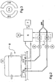
- Fig. 1 shows a schematic and simplified drawing of a domestic-use hob according to the present invention;
- Fig. 2 shows a partial block diagram of the hob of Fig. 1, on which a pot is placed; and
- Fig. 3 shows a top view of the cooking point included in Fig. 2.
- Both said description and said drawings are to be considered as non-limiting examples.
- Fig. 1 shows a gas hob for domestic use, indicated as a whole with
reference number 1, having four cooking points, each being indicated withreference number 2; eachcooking point 2 comprises at least one gas burner, indicated as a whole withreference number 21. One of the cooking points, shown in Fig. 3, comprises two gas burners, indicated withreference numbers burner 21B is divided into two parts which enclose theburner 21A. - The block diagram of Fig. 2 shows just one cooking point, i.e. the one of Fig. 3.
- On the
hob 1 shown in the drawings there are fiveknobs 9 corresponding to the number of gas burners of the fourcooking points 2; in fact, one cooking point comprises two burners; eachknob 9 allows the user to adjust the gas flow supplied to an associated burner. - The
hob 1 works on gas; the gas is supplied to the inlets of a number of safety valves, indicated as a whole with reference number 3, corresponding to the number ofburners 21; Fig. 2 shows just twovalves burners - The outlets of the safety valves 3 are connected to the respective burners through gas flow adjustment taps 10; the
taps 10 are as many as the number of burners, and are actuated by the user through therespective knobs 9. - The cooking point represented in Fig. 2 is fitted with a support element allowing the user to lay down the cook-ware over the two
burners - In Fig. 2, a pressure cooker has been laid down on the
support element 8; saidpressure cooker 8 has adetection system 5 being able to detect the temperature within thepressure cooker 8 and to transmit radio signals indicating the detected temperature values. -
Reference number 7 represents a timer being adjustable by the user. -
Reference number 4 represents a radio receiver. - The
hob 1 comprises anelectronic control system 6; thesystem 6 is connected to thetimer 7, thereceiver 4 and thevalves system 6 is connected to two thermocouples (not shown in Fig. 2) being associated with the twoburners - As said, Fig. 2 shows a partial block diagram of the hob of Fig. 1 and therefore, for example, shows neither any elements nor any connections related to the other three burners of the
hob 1. - The technical features of the present invention are as follows.
- The hob according to the present invention comprises at least one gas burner and cut-off means adapted to interrupt the gas supply to at least said burner; in the illustrated example, the cut-off means consist of the two
safety valves burners - The hob according to the present invention also comprises:
- reception means adapted to receive signals indicating values of at least one cooking parameter detected by a system, and
- an electronic control system being connected to the cut-off means and to the reception means, and adapted to control the cut-off means on the basis of signals received by the reception means, indicating values of at least one cooking parameter.
- The reception means are typically of the electronic type; in the illustrated example, they consist of the
radio receiver 4. - The detection system transmitting signals to the reception means is typically external to the hob; in the illustrated example, it consists of the
system 5. The detection system may be more or less complex; for instance, it may be adapted to operate autonomously and to detect and transmit the cooking parameter continuously or periodically; as an alternative, the detection system may be adapted to detect and transmit the cooking parameter only when interrogated by the electronic control system of the hob. The detection system may be active, i.e. supplied by an internal power source such as, for example, a battery - as described in the cited Patent DE2909129; alternately, the detection system may be passive, i.e. supplied by an external power source - as described in the cited Patent DE3225486. It is worth mentioning that detection systems adapted to cooperate with a hob according to the present invention are known at least in the patent literature, in particular in the above-mentioned Patents. - Depending on the implementation, the cooking parameter may be the temperature, the pressure or the humidity at which the cooking is taking place. Furthermore, the cooking parameters also include parameters being related to the "cooking time", i.e.: "cooking time elapsed", "remaining cooking time" and a "end of cooking" indication, the latter being the most direct one.
- Some of these cooking parameters are adapted to be used with particular types of cook-ware; for instance, cooking pressure may be used when a pressure cooker is employed.
- Of course, it is also possible to use more than one cooking parameter.
- The values of the parameter or the parameters are processed by the electronic control system of the hob. Sometimes this processing may be extremely simple; this is the case, for instance, when the cooking parameter corresponds to the "end of cooking" indication. It should be noted that the detection system may as well be adapted to perform an initial processing of the detected parameter values.
- According to the above teaching, cooking control is accomplished through simple cut-off means.
- As already mentioned, gas hobs are normally fitted with gas supply cut-off means; advantageously, this control exploits said means for other useful functions.
- Advantageously, according to the present invention, the reception means and the detection system are not connected through a cable; as a matter of fact, cables located near heat sources are easily subject to damage; moreover, cables near cooking points hinder the user's movements, preventing him/her to lay down and move the cook-ware with ease; in such a case, the reception means are adapted to receive optical signals (e.g. infrared signals), acoustic signals (e.g., ultrasound signals) or radio signals. Tests carried out have shown that infrared signals are most suited to kitchen use; besides, both infrared transmitters and infrared receivers are rather simple and cheap devices.
- The most typical cooking parameters which may be used in the present invention are cooking temperature and cooking pressure; moreover, these physical quantities can be detected through simple and cheap electronic devices; this is even more true for temperature.
- Cooking parameters such as cooking temperature and cooking pressure may be easily detected by a detection system being external but close to the hob, in particular close to the cooking point where the cooking takes place.
- Advantageously, the detection system is associated with a cook-ware and is applied, for example, to the bottom, to the sides or to the lid of said cook-ware.
- It should be noted that there are various "cooking temperatures" at a single cooking point, i.e.: flame temperature, temperature of the bottom of the cook-ware, temperature of the sides of the cook-ware, temperature of the lid of the cook-ware, temperature of the cooking liquid (water, oil,...), temperature of the cooking steam, temperature of the food cooked; all these temperatures may be detected; of course, some of these temperatures are more significant than others for the purposes of the present invention, i.e. typically temperature of the cooking liquid, temperature of the cooking steam and temperature of the food cooked.
- In the light of the above observation, it is clear that a detection system placed on the lid of the cooking cook-ware is in the ideal position for effectively detect the most significant "cooking temperatures", as in the example of Fig. 2.
- The cooking parameters related to "cooking time" may be detected easily through a timer. The timer may be located either in the hob or in a position being close to it, e.g. on the kitchen working top or table; the timer may also be integrated into other household appliances, e.g. an oven or a hood; it is apparent that the timer cannot be too far from the hob, because it must be easily set and activated when using the hob.
- In view of the above considerations, according to the present invention, it may be advantageous to provide the timer with transmission means adapted to transmit signals indicating a parameter related to the "cooking time" to reception means of the hob; if the timer is fitted with transmission means, it may be located anywhere. The timer may be more or less complex; for example, it may be adapted to operate autonomously, thus transmit the parameter related to the "cooking time" either continuously or periodically; alternately, the timer may be adapted to transmit the parameter related to the "cooking time" only when interrogated by the electronic control system of the hob. The timer may be active, i.e. supplied by an internal power source such as, for instance, a battery. Such an innovative timer may be used also in combination with cooking appliances being different from the one described herein, e.g. an electric hob.
- According to a preferred embodiment example of the present invention, the cook-ware is a pressure cooker, i.e. a cooking container having a lid which ensures a hermetic sealing; the pressure cooker lid is fitted with a valve being calibrated for opening under the action of a predefined pressure; this calibration is typically carried out during the manufacture of the pressure cooker and is set based on the maximum pressure which may be reached within the cook-ware during the cooking phase.
- On the lid there is also a temperature sensor which detects the temperature of the steam generated during the cooking and coming out of the valve when the pressure exceeds the calibration value. A temperature measurement thus allows to detect pressure variations within the cook-ware.
- As said, the hob according to the present invention comprises cut-off means adapted to interrupt the gas supply. In order to perform such a function, these means may advantageously be in just two operating conditions: an operating condition wherein gas is supplied, and an operating condition wherein gas is not supplied.
- Cut-off means having these characteristics may advantageously be produced through safety valves like those typically used in hobs; moreover, the same valves may be used to perform both the usual safety functions and the control functions according to the present invention.
- The hob according to the present invention may also comprise a timer, and its electronic control system may be adapted to control the cut-off means on the basis of signals sent by the timer; the cooking process may thus be controlled, for example, based both on cooking temperature or pressure and on cooking time. Such a timer may typically be set by the user, i.e. for the timer is adapted to count a time corresponding to the time interval, set by the user, being necessary to obtain properly cooked food; such a time interval may refer to the complete cooking of the food or just to a certain cooking phase.
- As previously described, the electronic control system being present on the hob processes the values of the cooking parameter or parameters coming from the reception means and therefore from the detection system.
- According to the present invention, the electronic control system can receive signals such as "start time counting" and/or "end time counting" from the timer; these signals sent to the electronic control system by the timer commonly indicate "start cooking" and "end of cooking", respectively.
- According to the present invention, the electronic control system can control the safety valves on the basis of the signals sent by the timer. When the signal sent by the timer corresponds to the "end" signal, the electronic control system can command the closing of a safety valve.
- According to a preferred embodiment of the present invention, the timer does not activate automatically as soon as it has been set by the user, but is activated by the electronic control system. The timer may, for example, store the user's setting and wait until its state is changed by the electronic control system.
- The timer activation may advantageously be performed by the electronic control system on the basis of signals indicating temperatures and/or pressures; such signals are typically received by the electronic control system through the reception means. According to a preferred embodiment of the present invention, when the temperature and/or pressure signals received by the reception means and processed by the electronic control system indicate a predefined temperature and/or pressure value, the control system activates the timer. Once activated by the electronic control system, the timer starts counting the time set by the user while the cooking goes on. Therefore, the user is given the advantage of being able to set all parameters being necessary to obtain a correct cooking when the cooking is started, thus giving over the entire cooking control to the hob.
- This solution using a timer whose activation is controlled by an electronic control system depending on signals (received by reception means being connected to the electronic control system) indicating values of at least one cooking parameter is not strictly limited to gas hobs; it may also be applied, for example, to electric hobs and offer the same benefits.
- As already mentioned, the present invention may be advantageously used in combination with pressure cookers, but it may also be applied to other types of cook-ware, preferably (but not necessarily) having a lid, such as, for example, pots for cooking pasta. As known, pasta is best cooked in boiling water; the various typologies of pasta (spaghetti, macaroni, etc.) reach their optimal cooking in typically different time intervals (5 minutes, 13 minutes, etc.); such intervals, being usually stated as a general recommendation on packs of pasta, should be understood from the moment when the water starts boiling; initially, the temperature of the water in the pot increases; this temperature value is sent by the detection system to the electronic control system, which processes it by comparing it with a predefined value, i.e. 100°C; when the water starts boiling, its temperature approaches the predefined value; the electronic control system causes the activation of the timer, which has been previously set by the user; the activated timer starts counting the time; when the preset time interval has elapsed, the timer sends a "end of cooking" signal; the electronic control system then controls the cut-off means, in particular the safety valve, so as to interrupt the gas supply to the burner; this terminates the cooking.
- The present invention may also be applied with great advantage to a gas hob comprising two or more gas burners being associated with the same cooking point. Typically, the hob will have a certain number of cooking points; one of these will comprise two burners, whereas the other cooking points will comprise just one burner.
- Cooking points comprising two burners are described, for example, in Patent IT1232887 in the name of the present Applicant; each of the two burners is connected to its own safety valve, its own thermocouple, its own tap and its own knob allowing the user to adjust the gas flow; the two burners are therefore totally independent from each other, though being associated with the same cooking point.
- If the present invention is applied to a cooking point comprising several burners having their own gas supply cut-off means, then it is possible to interrupt the gas supply to the burners in a selective way.
- In the case of the cooking point described in the cited Patent, being each of the two burners supplied by a respective safety valve, it is possible to operate the safety valves selectively, thereby cutting off the gas supply to the two burners separately; therefore it will be possible to extinguish the flame on either burner or on both burners. This provides an adjustment of the amount of heat supplied by the cooking point; furthermore, by selecting the appropriate structure and size of both burners it is possible to obtain a different thermal power depending on whether the flame is present on one burner, on the other burner or on both burners (e.g. 1KW or 2KW or 3KW).
- With this cooking point structure and thanks to the teaching of the present invention, through simple cut-off means it is therefore possible to obtain the desired power on the cooking point. This is advantageous from the energy consumption viewpoint as well, and consequently also in view of a reduction of the operating costs of the hob.
- According to an application of the present invention, when the cooking is started the user turns on the flame on both burners. The user then positions a pressure cooker on the support of the burning cooking point and sets the timer to the time being necessary for completing the cooking (e.g. 10 minutes). When the cooking has started, i.e. when the flame has been turned on underneath the pressure cooker, temperature and pressure within the pressure cooker increase. The value of the cooking temperature and/or pressure is detected by the detection system being present on the lid of the pressure cooker; this value is then sent to the electronic control system of the hob, which processes it and compares it with a stored value. When the detected value matches the stored one, the electronic control system activates the timer, thereby starting the counting of the time interval previously set by the user. As soon as the timer is started, the electronic control system commands one of the two safety valves so as to cut off the gas supply to one of the two burners, thereby reducing the amount of heat supplied to the pressure cooker. This is an advantageous solution; as a matter of fact, it is initially advantageous to obtain a rapid increase in temperature and pressure within the pressure cooker so that the food starts cooking quickly, whereas afterwards, i.e. during the actual cooking period, the pressure cooker may be provided with a reduced amount of heat being sufficient to keep constant the pressure within it. When the time interval set by the user has elapsed, the timer sends a "end of cooking" signal to the electronic control system of the hob, which closes the safety valve being still open. The gas supply to the cooking point is thus totally cut off, so that the cooking is terminated.
- The teachings of the present invention have been described herein as non-limiting examples related to gas hobs, but it should be understood that such teachings are also advantageously applicable, for example, to the so-called "cooking ranges". This term refers to a cooking appliance which is not integrated into a kitchen design; these household appliances usually comprise both a gas hob and a gas or electric oven in the same cabinet.
- It is perhaps worth specifying that the teachings of the present invention may be applied to hobs being supplied through a connection to either a gas cylinder or the public gas distribution main.
Claims (16)
- Hob (1) comprising at least one gas burner (21, 21A, 21B) and cut-off means (3, 3A, 3B) adapted to interrupt the gas supply to at least said burner (21, 21A, 21B), characterized in that it also comprises:- reception means (4) adapted to receive signals indicating values of at least one cooking parameter detected by a system (5), and- an electronic control system (6) being connected to said cut-off means (3, 3A, 3B) and to said reception means (4), and adapted to control said cut-off means (3, 3A, 3B) on the basis of signals received by said reception means (4), indicating values of at least one cooking parameter.
- Hob (1) according to claim 1, characterized in that said reception means (4) are adapted to receive optical, acoustic or radio signals.
- Hob (1) according to claim 1 or 2, characterized in that said cooking parameter is cooking temperature or cooking pressure.
- Hob (1) according to claim 1 or 2 or 3, characterized in that said system (5) is external to the hob (1).
- Hob (1) according to claim 4, characterized in that said system (5) is associated with a cook-ware (8).
- Hob (1) according to one of the previous claims, characterized in that said cut-off means (3, 3A, 3B) may be in two different operating conditions: an operating condition wherein gas is supplied and an operating condition wherein gas is not supplied.
- Hob (1) according to claim 6, characterized in that said cut-off means (3, 3A, 3B) comprise at least one safety valve (3A, 3B).
- Hob (1) according to one of the previous claims, characterized in that it also comprises a timer (7) and in that said electronic control system (6) is adapted to control said cut-off means (3, 3A, 3B) on the basis of signals sent by said timer (7).
- Hob (1) according to claim 8, characterized in that the timer (7) is adapted to be activated by said electronic control system (6).
- Hob (1) according to claim 8 or 9, characterized in that the timer (7) is adapted to be set by the user.
- Hob (1) according to claim 8 or 9 or 10, characterized in that the timer (7) is adapted to be activated on the basis of signals indicating temperatures and/or pressures.
- Hob (1) according to claim 11, characterized in that the timer (7) is adapted to be activated on the basis of signals received by said reception means (4).
- Hob (1) according to claim 11 or 12, characterized in that the timer (7) is adapted to be activated when the temperature and/or pressure signals received by said reception means (4) indicate a predefined temperature and/or pressure value.
- Hob (1) according to one of claims 8 to 13, characterized in that the cut-off means (3, 3A, 3B) are adapted to interrupt the gas supply at the end of a time interval set on the timer (7) by the user.
- Hob (1) according to one of the previous claims, characterized in that it comprises at least two gas burners (21A, 21B) being associated with the same cooking point (2), and in that said cut-off means (3A, 3B) are adapted to selectively interrupt the gas supply to the burners (21A, 21B) associated with the same cooking point (2).
- Hob (1) according to claim 15, characterized in that said electronic control system (6) is adapted to control said cut-off means (3A, 3B) so as to cut off the gas supply to one of the burners (21A, 21B) associated with the same cooking point (2) when the temperature and/or pressure signals received by said reception means (4) indicate a predefined temperature and/or pressure value.
Applications Claiming Priority (1)
| Application Number | Priority Date | Filing Date | Title |
|---|---|---|---|
| IT000631A ITTO20040631A1 (en) | 2004-09-21 | 2004-09-21 | GAS HOB WITH ELECTRONIC CONTROL SYSTEM |
Publications (2)
| Publication Number | Publication Date |
|---|---|
| EP1637808A2 true EP1637808A2 (en) | 2006-03-22 |
| EP1637808A3 EP1637808A3 (en) | 2009-10-07 |
Family
ID=35455850
Family Applications (1)
| Application Number | Title | Priority Date | Filing Date |
|---|---|---|---|
| EP05108211A Withdrawn EP1637808A3 (en) | 2004-09-21 | 2005-09-07 | Gas hob with electronic control system |
Country Status (3)
| Country | Link |
|---|---|
| EP (1) | EP1637808A3 (en) |
| IT (1) | ITTO20040631A1 (en) |
| RU (1) | RU2405117C2 (en) |
Cited By (3)
| Publication number | Priority date | Publication date | Assignee | Title |
|---|---|---|---|---|
| RU2476138C2 (en) * | 2007-06-19 | 2013-02-27 | Амц Интернейшенл Альфа Металкрафт Корпорейшен Аг | Device for displaying operating conditions of vessel for cooking |
| EP1917472B1 (en) * | 2005-08-16 | 2018-10-17 | BSH Hausgeräte GmbH | Timer for a gas cooking hob |
| ES2754878A1 (en) * | 2018-10-18 | 2020-04-20 | Bsh Electrodomesticos Espana Sa | Cooking system (Machine-translation by Google Translate, not legally binding) |
Families Citing this family (1)
| Publication number | Priority date | Publication date | Assignee | Title |
|---|---|---|---|---|
| RU182518U1 (en) * | 2018-03-30 | 2018-08-22 | Общество с ограниченной ответственностью "Альянс" | Desktop electric stove with automatic support of the set temperature for a specified amount of time |
Citations (3)
| Publication number | Priority date | Publication date | Assignee | Title |
|---|---|---|---|---|
| DE2909129A1 (en) | 1979-03-08 | 1980-09-11 | Horst Schultz | Cooking vessel lid temp. indicator - clipped around knob for lid which incorporates temp. monitor and switch for providing audible signal |
| DE3225486A1 (en) | 1982-07-08 | 1984-01-12 | Bbc Brown Boveri & Cie | METHOD AND DEVICE FOR POWERING MEASURING STATIONS OF A REMOTE MEASURING SYSTEM |
| IT1232887B (en) | 1989-07-27 | 1992-03-05 | Merloni Elettrodomestici Spa | GAS BURNER FOR COOKING FOOD |
Family Cites Families (4)
| Publication number | Priority date | Publication date | Assignee | Title |
|---|---|---|---|---|
| US3875854A (en) * | 1974-03-25 | 1975-04-08 | Raymond Lee Organization Inc | Apparatus for canning food |
| IT1283738B1 (en) * | 1996-04-15 | 1998-04-30 | Whirpool Europ S R L | GAS OPERATING APPLIANCE FOR HEATING AND / OR COOKING FOOD AND SIMILAR |
| US5851110A (en) * | 1996-09-05 | 1998-12-22 | Universal Tubular Systems, Inc. | Burner box without manifold return |
| US6413079B1 (en) * | 2000-04-10 | 2002-07-02 | Heat-N-Glo Fireplace Products, Inc. | Voice activated fireplace control system |
-
2004
- 2004-09-21 IT IT000631A patent/ITTO20040631A1/en unknown
-
2005
- 2005-09-07 EP EP05108211A patent/EP1637808A3/en not_active Withdrawn
- 2005-09-20 RU RU2005129350/03A patent/RU2405117C2/en not_active IP Right Cessation
Patent Citations (3)
| Publication number | Priority date | Publication date | Assignee | Title |
|---|---|---|---|---|
| DE2909129A1 (en) | 1979-03-08 | 1980-09-11 | Horst Schultz | Cooking vessel lid temp. indicator - clipped around knob for lid which incorporates temp. monitor and switch for providing audible signal |
| DE3225486A1 (en) | 1982-07-08 | 1984-01-12 | Bbc Brown Boveri & Cie | METHOD AND DEVICE FOR POWERING MEASURING STATIONS OF A REMOTE MEASURING SYSTEM |
| IT1232887B (en) | 1989-07-27 | 1992-03-05 | Merloni Elettrodomestici Spa | GAS BURNER FOR COOKING FOOD |
Cited By (3)
| Publication number | Priority date | Publication date | Assignee | Title |
|---|---|---|---|---|
| EP1917472B1 (en) * | 2005-08-16 | 2018-10-17 | BSH Hausgeräte GmbH | Timer for a gas cooking hob |
| RU2476138C2 (en) * | 2007-06-19 | 2013-02-27 | Амц Интернейшенл Альфа Металкрафт Корпорейшен Аг | Device for displaying operating conditions of vessel for cooking |
| ES2754878A1 (en) * | 2018-10-18 | 2020-04-20 | Bsh Electrodomesticos Espana Sa | Cooking system (Machine-translation by Google Translate, not legally binding) |
Also Published As
| Publication number | Publication date |
|---|---|
| EP1637808A3 (en) | 2009-10-07 |
| RU2405117C2 (en) | 2010-11-27 |
| ITTO20040631A1 (en) | 2004-12-21 |
| RU2005129350A (en) | 2007-04-10 |
Similar Documents
| Publication | Publication Date | Title |
|---|---|---|
| US9027469B2 (en) | Method for controlling a cooking process | |
| US5746114A (en) | Intelligent cooking system with wireless control | |
| CN106969386B (en) | A smart gas stove | |
| EP2661994B1 (en) | Liquid heating vessel and control | |
| KR101738830B1 (en) | System and method of controlling gas shutting of gas range | |
| US20140234496A1 (en) | System and methods of improving the performance, safety and energy efficiency of a cooking appliance | |
| EP2775212B1 (en) | Method of operating a cooking appliance, control unit and cooking applicance | |
| CN107013951A (en) | A kind of pot and stove device | |
| US10584882B2 (en) | Electric cooktop appliance with heat control | |
| KR101413983B1 (en) | Automatic apparatus for judging nob position of gas range and control method for preventing overheating using the apparatus | |
| US20210172602A1 (en) | Closed-loop simmer with a gas burner | |
| CN108968660A (en) | Electric pressure cooker | |
| CN110701639A (en) | Intelligent soup cooking method capable of automatically identifying different pots and control device | |
| CN109611899B (en) | Gas stove and control method for gas stove | |
| CN109708160B (en) | Gas stove and control method for gas stove | |
| WO2018051178A1 (en) | System for automating the switching on, adjustment and/or switching off of one or more accessories for cooktops | |
| CN210425132U (en) | Gas kitchen ranges | |
| KR20130122265A (en) | Apparatus and method for prevent overheating of cooking vessel by thermal conductivity | |
| CN210425133U (en) | Gas stoves | |
| CN211372511U (en) | Intelligent temperature control stove | |
| RU2405117C2 (en) | Gas stove with electronic control system | |
| KR102263780B1 (en) | Smart automatic burner control system | |
| US20030085222A1 (en) | Cooking appliance | |
| KR20160047685A (en) | Cooking receptacle for electric range | |
| JP6986484B2 (en) | Information notification system for cooking utensils |
Legal Events
| Date | Code | Title | Description |
|---|---|---|---|
| PUAI | Public reference made under article 153(3) epc to a published international application that has entered the european phase |
Free format text: ORIGINAL CODE: 0009012 |
|
| AK | Designated contracting states |
Kind code of ref document: A2 Designated state(s): AT BE BG CH CY CZ DE DK EE ES FI FR GB GR HU IE IS IT LI LT LU LV MC NL PL PT RO SE SI SK TR |
|
| AX | Request for extension of the european patent |
Extension state: AL BA HR MK YU |
|
| PUAL | Search report despatched |
Free format text: ORIGINAL CODE: 0009013 |
|
| AK | Designated contracting states |
Kind code of ref document: A3 Designated state(s): AT BE BG CH CY CZ DE DK EE ES FI FR GB GR HU IE IS IT LI LT LU LV MC NL PL PT RO SE SI SK TR |
|
| AX | Request for extension of the european patent |
Extension state: AL BA HR MK YU |
|
| 17P | Request for examination filed |
Effective date: 20100330 |
|
| AKX | Designation fees paid |
Designated state(s): AT BE BG CH CY CZ DE DK EE ES FI FR GB GR HU IE IS IT LI LT LU LV MC NL PL PT RO SE SI SK TR |
|
| STAA | Information on the status of an ep patent application or granted ep patent |
Free format text: STATUS: THE APPLICATION IS DEEMED TO BE WITHDRAWN |
|
| 18D | Application deemed to be withdrawn |
Effective date: 20120403 |