EP1637789A1 - Pressure regulator for fluid with manometer - Google Patents
Pressure regulator for fluid with manometer Download PDFInfo
- Publication number
- EP1637789A1 EP1637789A1 EP20050019955 EP05019955A EP1637789A1 EP 1637789 A1 EP1637789 A1 EP 1637789A1 EP 20050019955 EP20050019955 EP 20050019955 EP 05019955 A EP05019955 A EP 05019955A EP 1637789 A1 EP1637789 A1 EP 1637789A1
- Authority
- EP
- European Patent Office
- Prior art keywords
- manometer
- pressure
- bearing
- holder
- regulator
- Prior art date
- Legal status (The legal status is an assumption and is not a legal conclusion. Google has not performed a legal analysis and makes no representation as to the accuracy of the status listed.)
- Granted
Links
- 239000012530 fluid Substances 0.000 title claims description 21
- 238000010079 rubber tapping Methods 0.000 claims description 2
- 230000001105 regulatory effect Effects 0.000 claims 1
- 230000008878 coupling Effects 0.000 description 3
- 238000010168 coupling process Methods 0.000 description 3
- 238000005859 coupling reaction Methods 0.000 description 3
- 238000009434 installation Methods 0.000 description 3
- 238000007789 sealing Methods 0.000 description 2
- 230000001154 acute effect Effects 0.000 description 1
- 238000004891 communication Methods 0.000 description 1
- 230000006735 deficit Effects 0.000 description 1
- 230000001419 dependent effect Effects 0.000 description 1
- 238000013461 design Methods 0.000 description 1
- 238000011161 development Methods 0.000 description 1
- 230000018109 developmental process Effects 0.000 description 1
- 238000012423 maintenance Methods 0.000 description 1
- 238000004519 manufacturing process Methods 0.000 description 1
- 230000002093 peripheral effect Effects 0.000 description 1
- 238000009420 retrofitting Methods 0.000 description 1
- 230000035939 shock Effects 0.000 description 1
- 238000011144 upstream manufacturing Methods 0.000 description 1
- 238000009423 ventilation Methods 0.000 description 1
- 238000013022 venting Methods 0.000 description 1
Images


Classifications
-
- G—PHYSICS
- G05—CONTROLLING; REGULATING
- G05D—SYSTEMS FOR CONTROLLING OR REGULATING NON-ELECTRIC VARIABLES
- G05D16/00—Control of fluid pressure
- G05D16/04—Control of fluid pressure without auxiliary power
- G05D16/06—Control of fluid pressure without auxiliary power the sensing element being a flexible membrane, yielding to pressure, e.g. diaphragm, bellows, capsule
- G05D16/063—Control of fluid pressure without auxiliary power the sensing element being a flexible membrane, yielding to pressure, e.g. diaphragm, bellows, capsule the sensing element being a membrane
- G05D16/0644—Control of fluid pressure without auxiliary power the sensing element being a flexible membrane, yielding to pressure, e.g. diaphragm, bellows, capsule the sensing element being a membrane the membrane acting directly on the obturator
- G05D16/0663—Control of fluid pressure without auxiliary power the sensing element being a flexible membrane, yielding to pressure, e.g. diaphragm, bellows, capsule the sensing element being a membrane the membrane acting directly on the obturator using a spring-loaded membrane with a spring-loaded slideable obturator
-
- Y—GENERAL TAGGING OF NEW TECHNOLOGICAL DEVELOPMENTS; GENERAL TAGGING OF CROSS-SECTIONAL TECHNOLOGIES SPANNING OVER SEVERAL SECTIONS OF THE IPC; TECHNICAL SUBJECTS COVERED BY FORMER USPC CROSS-REFERENCE ART COLLECTIONS [XRACs] AND DIGESTS
- Y10—TECHNICAL SUBJECTS COVERED BY FORMER USPC
- Y10T—TECHNICAL SUBJECTS COVERED BY FORMER US CLASSIFICATION
- Y10T137/00—Fluid handling
- Y10T137/2496—Self-proportioning or correlating systems
- Y10T137/2544—Supply and exhaust type
-
- Y—GENERAL TAGGING OF NEW TECHNOLOGICAL DEVELOPMENTS; GENERAL TAGGING OF CROSS-SECTIONAL TECHNOLOGIES SPANNING OVER SEVERAL SECTIONS OF THE IPC; TECHNICAL SUBJECTS COVERED BY FORMER USPC CROSS-REFERENCE ART COLLECTIONS [XRACs] AND DIGESTS
- Y10—TECHNICAL SUBJECTS COVERED BY FORMER USPC
- Y10T—TECHNICAL SUBJECTS COVERED BY FORMER US CLASSIFICATION
- Y10T137/00—Fluid handling
- Y10T137/7722—Line condition change responsive valves
- Y10T137/7781—With separate connected fluid reactor surface
- Y10T137/7793—With opening bias [e.g., pressure regulator]
- Y10T137/7794—With relief valve
-
- Y—GENERAL TAGGING OF NEW TECHNOLOGICAL DEVELOPMENTS; GENERAL TAGGING OF CROSS-SECTIONAL TECHNOLOGIES SPANNING OVER SEVERAL SECTIONS OF THE IPC; TECHNICAL SUBJECTS COVERED BY FORMER USPC CROSS-REFERENCE ART COLLECTIONS [XRACs] AND DIGESTS
- Y10—TECHNICAL SUBJECTS COVERED BY FORMER USPC
- Y10T—TECHNICAL SUBJECTS COVERED BY FORMER US CLASSIFICATION
- Y10T137/00—Fluid handling
- Y10T137/8158—With indicator, register, recorder, alarm or inspection means
- Y10T137/8326—Fluid pressure responsive indicator, recorder or alarm
Definitions
- US Pat. No. 5,713,609 discloses a coupling device for producing a fluidic connection. It contains two coupling parts, which are rotatably mounted on each other and each having a fluid port. The fluid connections are constantly connected to each other regardless of the relative rotational position of the coupling parts via channels and an annular groove.
- stepless or stepped multiple intermediate display positions can be set. At least if a stepwise positioning is provided, it is possible, for example, to enable positioning in optionally four display positions, each pivoted by 30 ° relative to one another. Also particularly useful would be a positionability in three by 45 ° staggered display positions, the average display position is preferably midway between the two main display positions.
- the invention can be used with advantage in all fluid power devices that have at least one pressure regulator. Particularly recommended, the invention proves in conjunction with a valve device, which also has one or more multi-way valves in addition to one or more pressure regulators.
- the working pressure which can be tapped off at the two connection openings 15 can thus be adjusted individually in the exemplary embodiment.
- the pressure control means 18 include an axially movable valve member 19 which is turned on in the connection between a primary channel 22 and a secondary channel 23 and which has an actuating tappet 24 which cooperates with an actuating piston 25, which one constantly with the secondary channel 23 connected control chamber 26 limited.
- the actuating piston 25 is constantly under the pressure prevailing in the secondary channel 23 secondary pressure.
- primary channel 22 and secondary channel 23 are formed by two consecutive branches of a working channel 14.
- the actuating piston 25 may also be provided an actuating diaphragm.
- the pressure regulator 17 of the embodiment is equipped with so-called secondary ventilation measures. If the pressure in the secondary channel 23 increases beyond the desired level, the actuating piston 25 lifts off from the actuating tappet 24, which does not follow further, so that a vent opening 32 is released, via which pressure medium can flow out of the control chamber 26 to the atmosphere.
- the pressure gauges 38 in all pressure regulators 17 are fixed at the same distance from the axis of rotation 46 on the associated manometer holder 44. Due to the resulting mutual interference, adjacent gauges 38 may not be positioned with identical orientation. In order to avoid this impairment, directly adjacent pressure gauges 38 can be fixed to gauge gauges 44 of different lengths as needed, resulting in different distances from the axis of rotation 46, which are chosen so large that the gauge gauges 44 pass each other without colliding the gauges 38 carried by them can be pivoted. Such an embodiment is indicated in Fig. 3, where a pressure gauge 38a is shown which, in conjunction with an extended manometer holder 44, can swing past the immediately adjacent pressure gauge 38 without collision.
- a detachable, in particular by latching, fixed closure body 65 is inserted when manometer 44 installed in the mounting aperture 64. It protrudes with a stopper portion 66 in the space between the two bearing eyes 48, 49 and is thus in the pivoting path of the support arm 55, so that it limits the pivot angle.
- the second main display position can thereby be specified.
- the first main display position can be effected, in particular, by an emergence of the support arm 55 on that part of the regulator housing 37 which carries the two bearing eyes 48, 49.
Abstract
Description
Die Erfindung betrifft ein fluidtechnisches Gerät, ausgestattet mit mindestens einem eine Längsachse und eine dazu rechtwinkelige Hochachse aufweisenden Druckregler, dessen Reglergehäuse stirnseitig mit einem Manometer bestückt ist, das den über einen Abgriffskanal aus dem Reglergehäuse abgegriffenen Sekundärdruck anzeigt und das bezüglich des Reglergehäuses in unterschiedlichen Ausrichtungen positionierbar ist, um die Ablesbarkeit seiner Anzeigefläche aus unterschiedlichen Blickrichtungen zu gewährleisten.The invention relates to a fluid power device, equipped with at least one longitudinal axis and a perpendicular vertical axis having pressure regulator, the regulator housing is equipped at the front with a pressure gauge, which indicates the tapped via a tap channel from the regulator housing secondary pressure and positioned relative to the regulator housing in different orientations is to ensure the readability of its display area from different viewing directions.
Ein fluidtechnisches Gerät dieser Art geht aus dem "Pneumatik-Katalog-D-11/02; Ventile; Serie 2005/2012", Seiten V-77 bis V-79, der Firma Numatics hervor. Es handelt sich bei dem dortigen Gerät um ein Ventilgerät, bei dem eine Grundplatte mit mehreren in einer Aufreihungsrichtung Seite an Seite angeordneten Mehrwegeventilen bestückt ist, wobei einige Mehrwegeventile auf einer Zwischenplatte sitzen, an die an einer oder beiden Stirnseiten ein Druckregler angebaut ist, mit dem sich der Druck der zum oder vom Mehrwegeventil strömenden Druckluft auf einen gewünschten Sekundärdruck herunterregeln lässt. Der eingestellte Sekundärdruck kann an einem stirnseitig am betreffenden Reglergehäuse angeordneten Manometer abgelesen werden. Um unterschiedlichen Einbausituationen des fluidtechnischen Gerätes Rechnung tragen zu können, kann das Manometer alternativ in zwei unterschiedlichen Ausrichtungen installiert werden, wobei seine Anzeigefläche entweder in Richtung der Längsachse des Druckreglers oder in Richtung der Hochachse des Druckreglers weist. In der einen Ausrichtung wird das Manometer direkt am Reglergehäuse installiert. Zum Erhalt der anderen Ausrichtung wird zwischen das Manometer und das Reglergehäuse ein um 90° abgebogenes Winkelanschlussstück eingebaut. Diese Umrüstmaßnahmen sind relativ zeitraubend und können überdies nur im stillgesetzten Zustand des fluidtechnischen Gerätes vorgenommen werden.A fluid power device of this kind is evident from the "Pneumatic Catalog D-11/02; Valves, Series 2005/2012", pages V-77 to V-79, the company Numatics. It is at the local device is a valve device in which a base plate is equipped with several arranged in a Aufreihungsrichtung side by side multiway valves, with some multiway valves sitting on an intermediate plate to which a pressure regulator is attached to one or both end faces, with the the pressure of the compressed air flowing to or from the multi-way valve can be reduced to a desired secondary pressure. The set secondary pressure can be read on a front side of the relevant controller housing pressure gauge. In order to accommodate different installation situations of the fluid power device, the pressure gauge can alternatively in two different orientations be installed, with its display surface facing either in the direction of the longitudinal axis of the pressure regulator or in the direction of the vertical axis of the pressure regulator. In one orientation, the pressure gauge is installed directly on the regulator housing. To obtain the other orientation, an angle fitting bent by 90 ° is installed between the pressure gauge and the controller housing. These retrofitting measures are relatively time-consuming and, moreover, can only be carried out in the stopped state of the fluid power device.
Aus der US 4 823 835 geht ein Schwenkverbinder hervor, der einen mit einem Ventil ausgestatteten, einen Fluidauslass aufweisenden Grundkörper und ein an dem Grundkörper um dessen Längsachse verschwenkbar gelagertes Schwenkteil aufweist, wobei das Schwenkteil seinerseits einen einen Fluideinlass aufweisenden verschwenkbaren Anschlußkörper trägt. Stirnseitig an dem Schwenkteil kann zusätzlich ein Manometer befestigt werden. Das Manometer steht mit einem Kanal des Schwenkteils in Verbindung, der unabhängig von der Schwenkposition des Schwenkteils ständig mit einem Kanal des Grundkörpers verbunden ist.US Pat. No. 4,823,835 discloses a pivoting connector which has a base body provided with a valve, a fluid outlet and a pivoting part pivotably mounted on the base body about its longitudinal axis, the pivoting part in turn carrying a pivotable connection body having a fluid inlet. On the front side of the pivoting part, a manometer can be additionally attached. The manometer is connected to a channel of the pivoting part in connection, which is independent of the pivot position of the pivoting part constantly connected to a channel of the body.
Die DE 102 59 395 A1 beschreibt ein Anschlußstück für Fluidleitungen mit einem an einem Grundkörper um dessen Längsachse verschwenkbar gelagerten Schwenkteil. Ein in dem Schwenkteil verlaufender Kanal steht unabhängig von der Schwenkposition ständig mit einem Kanal des Grundkörpers in Verbindung.DE 102 59 395 A1 describes a connecting piece for fluid lines with a pivotable mounted on a base body about its longitudinal axis pivoting part. A running in the pivot member channel is independent of the pivot position constantly with a channel of the body in combination.
Aus der US 5 713 609 geht eine zur Herstellung einer fluidischen Verbindung dienende Kupplungseinrichtung hervor. Sie enthält zwei Kupplungsteile, die drehbar aneinander gelagert sind und jeweils einen Fluidanschluß aufweisen. Die Fluidanschlüsse sind unabhängig von der relativen Drehposition der Kupplungsteile über Kanäle und eine Ringnut ständig miteinander verbunden.US Pat. No. 5,713,609 discloses a coupling device for producing a fluidic connection. It contains two coupling parts, which are rotatably mounted on each other and each having a fluid port. The fluid connections are constantly connected to each other regardless of the relative rotational position of the coupling parts via channels and an annular groove.
Es ist die Aufgabe der vorliegenden Erfindung, ein fluidtechnisches Gerät der eingangs genannten Art zu schaffen, dessen Druckregler sich einfacher und schneller hinsichtlich unterschiedlicher Einbausituationen des fluidtechnischen Gerätes umrüsten lässt.It is the object of the present invention to provide a fluid power device of the type mentioned, whose pressure regulator can be converted easier and faster with respect to different installation situations of the fluid power device.
Zur Lösung dieser Aufgabe ist der betreffende Druckregler mit einem das Manometer tragenden Manometerhalter ausgestattet, der ohne Unterbrechung des Abgriffkanals relativ zum Reglergehäuse um eine zur Längsachse und zur Hochachse des Druckreglers rechtwinkelige Drehachse in verschiedene Anzeigepositionen verschwenkbar ist.To solve this problem, the pressure regulator in question is equipped with a manometer holder carrying the pressure gauge, which can be pivoted into different display positions relative to the regulator housing without interruption of the tap channel about a rotational axis perpendicular to the longitudinal axis and the vertical axis of the pressure regulator.
Auf diese Weise kann die Ausrichtung des Manometers ohne Verwendung zusätzlicher Bauteile und ohne Betriebsunterbrechung des Gerätes durch einfaches Verschwenken des mit dem Manometer bestückten Manometerhalters variiert werden. Wird ein entsprechender Schwenkwinkel bereitgestellt, kann das Manometer beispielsweise wahlweise horizontal oder vertikal ausgerichtet werden, um ein Ablesen der Manometerwerte beispielsweise von vorne oder von oben zu ermöglichen. Sind innerhalb des fluidtechnischen Gerätes mehrere mit Manometer versehene Druckregler nebeneinanderliegend angeordnet, deren Baubreite geringer ist als der Durchmesser des Manometers, kann überdies die Möglichkeit geschaffen werden, benachbarte Manometerhalter in schwenkwinkelmäßig voneinander abweichenden Anzeigepositionen zu positionieren, sodass die Manometer nicht miteinander kollidieren, gleichwohl jedoch die Ausrichtungen nur wenig divergieren und somit trotz der unterschiedlichen Winkellagen beispielsweise die Möglichkeit bestehen kann, eine Ablesung sämtlicher Manometer, je nach Ausrichtung, von vorne oder von oben vorzunehmen. Um eine gegenseitige Kollision benachbarter Manometer auszuschließen, können deren Manometerhalter bei Bedarf auch unterschiedlich lang ausgeführt sein, sodass sich die Abstände zwischen Manometer und Drehachse bei benachbarten Druckreglern um ein Maß voneinander unterscheiden können, das beim Verschwenken eine gegenseitige Behinderung ausschließt.In this way, the orientation of the manometer without using additional components and without interrupting the operation of the device by simply pivoting the equipped with the manometer gauge holder can be varied. If a corresponding swivel angle is provided, the pressure gauge can be aligned, for example, optionally horizontally or vertically, in order to allow reading of the pressure gauge values, for example from the front or from above. If several pressure regulators provided with pressure gauges are arranged side by side within the fluid power device, the width of which is less than the diameter of the manometer, the possibility can also be created to position adjacent manometer holders in display positions that differ from one another in terms of pivoting angle, so that the pressure gauges do not collide with one another, however Alignments only slightly diverge and thus, despite the different angular positions, for example, there may be the possibility to make a reading of all pressure gauges, depending on the orientation, from the front or from above. In order to exclude a mutual collision of adjacent pressure gauges, the manometer holders can also be of different lengths if required be so that the distances between the pressure gauge and axis of rotation in adjacent pressure regulators may differ by a degree from each other, which excludes mutual obstruction during pivoting.
Vorteilhafte Weiterbildungen der Erfindung gehen aus den Unteransprüchen hervor.Advantageous developments of the invention will become apparent from the dependent claims.
Es ist von Vorteil, wenn der Manometerhalter des jeweiligen Druckreglers wahlweise wenigstens in einer ersten und einer zweiten Haupt-Anzeigeposition positionierbar ist, wobei die Anzeigefläche des Manometers in der ersten Haupt-Anzeigeposition in Richtung der Hochachse und in der zweiten Haupt-Anzeigeposition in Richtung der Längsachse weist.It is advantageous if the pressure gauge holder of the respective pressure regulator is selectively positionable in at least a first and a second main display position, wherein the display surface of the pressure gauge in the first main display position in the direction of the vertical axis and in the second main display position in the direction of Longitudinal axis points.
Es ist eine dahingehende Ausgestaltung möglich, dass zwischen den Haupt-Anzeigepositionen stufenlos oder abgestuft mehrere Zwischen-Anzeigepositionen eingestellt werden können. Zumindest wenn eine stufenweise Positionierung vorgesehen ist, ist es beispielsweise möglich, eine Positionierbarkeit in wahlweise vier jeweils um 30° gegeneinander verschwenkten Anzeigepositionen zu ermöglichen. Besonders zweckmäßig wäre auch eine Positionierbarkeit in drei jeweils um 45° gegeneinander versetzten Anzeigepositionen, wobei die mittlere Anzeigeposition vorzugsweise winkelmittig zwischen den beiden Hauptanzeigepositionen liegt.It is a pertinent embodiment possible that between the main display positions stepless or stepped multiple intermediate display positions can be set. At least if a stepwise positioning is provided, it is possible, for example, to enable positioning in optionally four display positions, each pivoted by 30 ° relative to one another. Also particularly useful would be a positionability in three by 45 ° staggered display positions, the average display position is preferably midway between the two main display positions.
Die Schwenklagerung des Manometerhalters wird vorzugsweise über einen zylindrischen Lagerabschnitt des Manometerhalters realisiert, der in einer daran angepassten Lageraufnahme des Reglergehäuses drehbar gelagert ist.The pivot bearing of the manometer holder is preferably realized via a cylindrical bearing portion of the manometer holder, which is rotatably mounted in a bearing receptacle adapted thereto of the regulator housing.
Das Manometer kann an einem quer und insbesondere rechtwinkelig zur Drehachse vom Lagerabschnitt wegragenden Tragarm des Manometerhalters sitzen, wobei die Anzeigefläche insbesondere in Richtung der Längsachse des Tragarmes weist. Die Lageraufnahme kann dabei von zwei zueinander beabstandeten Lageraugen des Reglergehäuses gebildet sein, zwischen denen der Tragarm hindurchgreift und in die der Lagerabschnitt mit axial beidseits des Tragarmes liegenden Lagerfortsätzen verdrehbar eintaucht. Wenigstens ein Lagerauge verfügt umfangsseitig über eine Montagedurchbrechung, die bei entsprechender Schwenkposition des Manometerhalters einen Durchtritt des Tragarmes zum Zwecke dessen Montage oder Demontage zulässt. In der Montagedurchbrechung ist zweckmäßigerweise ein Verschlusskörper lösbar fixiert.The manometer can sit on a transversely and in particular at right angles to the axis of rotation of the bearing portion projecting arm of the pressure gauge holder, wherein the display surface in particular points in the direction of the longitudinal axis of the support arm. The bearing receptacle can be formed by two spaced-apart bearing eyes of the regulator housing, between which engages the support arm and in which the bearing portion rotatably immersed with axially lying on both sides of the support arm bearing extensions. At least one bearing eye has a mounting aperture on the circumference, which allows a passage of the support arm for the purpose of its assembly or disassembly at a corresponding pivot position of the manometer holder. In the assembly aperture a closure body is expediently releasably fixed.
Um eine stufenweise Positionierung des Manometerhalters zu ermöglichen, können Rastmittel vorgesehen sein, die eine verrastende Fixierung des Manometerhalters bezüglich des Reglergehäuses in der jeweils gewünschten Anzeigeposition zulassen. Beispielsweise kann der Lagerabschnitt am Außenumfang einen Zahnkranz aufweisen, in den ein am Reglergehäuse fixiertes federndes Rastelement eingreift.In order to enable a stepwise positioning of the manometer holder, latching means can be provided which allow latching fixing of the manometer holder with respect to the regulator housing in the respective desired display position. For example, the bearing portion may have a ring gear on the outer circumference, in which engages a fixed latching element fixed to the regulator housing.
Die Erfindung ist bei allen fluidtechnischen Geräten mit Vorteil einsetzbar, die über mindestens einen Druckregler verfügen. Besonders empfehlenswert erweist sich die Erfindung in Verbindung mit einem Ventilgerät, das zusätzlich zu einem oder mehreren Druckreglern auch noch ein oder mehrere Mehrwegeventile aufweist.The invention can be used with advantage in all fluid power devices that have at least one pressure regulator. Particularly recommended, the invention proves in conjunction with a valve device, which also has one or more multi-way valves in addition to one or more pressure regulators.
Nachfolgend wird die Erfindung anhand der beiliegenden Zeichnung näher erläutert. In dieser zeigen:
- Fig. 1
- eine bevorzugte Bauform des erfindungsgemäßen fluidtechnischen Gerätes in einer Ausgestaltung als Ventilgerät, wobei der besseren Übersichtlichkeit wegen nur eine von mehreren längsseits nebeneinander angeordneten Steuereinheiten ge- zeigt ist, die unter anderem ein Mehrwegeventil und wenigstens einen Druckregler beinhaltet,
- Fig. 2
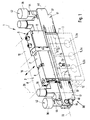
- einen Ausschnitt des Gerätes aus Fig. 1, wobei die auf der gleichen Seite platzierten Druckregler mehrerer benachbarter Steuereinheiten mit unterschiedlich positionierten Manometern sichtbar sind,
- Fig. 3
- die Anordnung aus Fig. 2 in einer Vorderansicht mit Blickrichtung gemäß Pfeil III,
- Fig. 4
- einen Längsschnitt durch eine Steuereinheit im Bereich des Druckreglers gemäß Schnittlinie IV-IV aus Fig. 2 und 5,
- Fig. 5
- einen Schnitt durch die Anordnung aus Fig. 4 im Bereich eines Manometers und des diesen tragenden Manometerhalters, gemäß Schnittlinie V-V aus Fig. 4,
- Fig. 6
- eine vergrößerte Detailansicht des stirnseitigen Endbereiches eines Druckreglers mit Blickrichtung gemäß Pfeil VI von unten her und
- Fig. 7
- einen für Fernabfrage modifizierten Druckregler in einer Seitenansicht in Einzeldarstellung.
- Fig. 1
- a preferred design of the fluid power device according to the invention in an embodiment as a valve device, wherein for the sake of clarity, only one of a plurality of longitudinally juxtaposed control units GE shows, among other things, includes a multi-way valve and at least one pressure regulator,
- Fig. 2
- 1 shows a detail of the device of FIG. 1, wherein the pressure regulators of several adjacent control units placed on the same side are visible with differently positioned pressure gauges,
- Fig. 3
- the arrangement of Figure 2 in a front view looking in accordance with arrow III,
- Fig. 4
- 3 a longitudinal section through a control unit in the region of the pressure regulator according to section line IV-IV from FIGS. 2 and 5,
- Fig. 5
- 4 shows a section through the arrangement of FIG. 4 in the region of a manometer and the manometer holder carrying it, according to section line VV from FIG. 4, FIG.
- Fig. 6
- an enlarged detail view of the front end portion of a pressure regulator with a view according to arrow VI from below and
- Fig. 7
- a remote control modified pressure regulator in a side view in an individual view.
Bei dem in der Zeichnung abgebildeten fluidtechnischen Gerät 1 handelt es sich um ein Ventilgerät, in dem mehrere Mehrwegeventile 2 unter Einbeziehung weiterer Komponenten zu einer Baugruppe zusammengefasst sind. Das Gerät 1 wird mit Druckluft betrieben, wenngleich prinzipiell auch eine hydraulische Betriebsart in Frage kommt.The illustrated in the drawing
Das Gerät 1 verfügt über eine einstückige oder, wie beim Ausführungsbeispiel, modular aufgebaute Grundplatte 3, die in Fig. 1 strichpunktiert angedeutet ist und die in Richtung ihrer Längsachse 4 von mehreren Zentralkanälen 5 durchsetzt ist. Die Zentralkanäle 5 sind beim Ausführungsbeispiel ein Speisekanal 5a, über den das zu steuernde Druckmedium eingespeist wird, sowie zwei Entlüftungskanäle 5b, 5c, über die die von den Verbrauchern zurückströmende Druckluft abgeführt wird.The
Auf der Grundplatte 3 befinden sich mehrere Bestückungsplätze, die jeweils mit einer Steuereinheit 6 bestückt sind, von denen in Fig. 1 nur eine dargestellt ist. Die Fig. 2 zeigt die stirnseitigen Endabschnitte von vieren der auf der Grundplatte 3 platzierten Steuereinheiten 6.On the base plate 3 there are several placement places, which are each equipped with a control unit 6, of which in Fig. 1, only one is shown. FIG. 2 shows the end-side end sections of four of the control units 6 placed on the base plate 3.
Jede Steuereinheit 6 verfügt über eine direkt auf der Grundplatte 3 sitzende Zwischenplatte 7 länglicher Gestalt, auf der ein elektrisch aktivierbares Mehrwegeventil 2 befestigt ist. Das Mehrwegeventil 2 hat einen in konventioneller Weise mit einem nicht näher dargestellten Ventilschieber ausgestatteten Steuerteil 8 und einen daran angeordneten elektrischen Antriebsteil 12, beispielsweise in Gestalt eines oder mehrerer Magnetventile.Each control unit 6 has an intermediate plate 7 of elongated shape sitting directly on the base plate 3, on which an electrically activatable
Von den Zentralkanälen 5 ausgehende Zweigkahäle 13 durchsetzen die Grundplatte 3 und die daran sitzende Zwischenplatte 7 und stehen mit dem auf der Zwischenplatte 7 sitzenden Steuerteil 8 in fluidischer Verbindung. In ähnlicher Weise sind jeder Steuereinheit 6 zwei Arbeitskanäle 14 zugeordnet, die ausgehend vom Steuerteil 8 die Zwischenplatte 7 durchsetzen und anschließend in der Grundplatte 3 verlaufen, bis sie dort über Anschlussöffnungen 15 ausmünden, an denen ein zu betätigender Verbraucher, beispielsweise ein durch Fluidkraft aktivierbarer Antrieb, anschließbar ist. Die diversen Kanäle sind in Fig. 1 lediglich schematisch angedeutet.From the central channels 5
Die Steuereinheiten 6 und mithin auch die Mehrwegeventile 2 und die diesen zugeordneten Zwischenplatten 7 sind in einer durch einen Doppelpfeil 16 angedeuteten Aufreihungsrichtung längsseits nebeneinanderliegend aufeinanderfolgend angeordnet. Die Längsachsen der Mehrwegeventile 2 und der Zwischenplatten 7 sind rechtwinkelig zu der Aufreihungsrichtung 16 ausgerichtet, wobei an jeder der beiden in Richtung der zugeordneten Längsachse orientierten Stirnseiten der Zwischenplatte 7 ein Druckregler 17 angebaut ist. Jeder Druckregler 17 ist, schaltungstechnisch gesehen, in den Verlauf eines der beiden Arbeitskanäle 14 eingeschaltet, wobei aus Fig. 4 die allgemein mit Bezugsziffer 18 bezeichneten vorgeschalteten und nachgeschalteten Arbeitskanalabschnitte 14a, 14b ersichtlich sind.The control units 6 and thus also the
Über die Druckregler einer jeweiligen Steuereinheit 6 kann somit beim Ausführungsbeispiel der an den beiden Anschlussöffnungen 15 abgreifbare Arbeitsdruck individuell eingestellt werden.By way of the pressure regulator of a respective control unit 6, the working pressure which can be tapped off at the two
Mit den Druckreglern 17 können auch andere Regelungsaufgaben übernommen werden, insbesondere in Verbindung mit dem Anschluss an andere der die Zwischenplatte 7 durchsetzenden Kanäle. Beispielsweise wäre eine Einschaltung in den vom Speisekanal 5a kommenden Zweigkanal 13 denkbar, um den dem Mehrwegeventil 2 der betreffenden Steuereinheit 6 zugeführten Speisedruck individuell einzustellen. Ist lediglich der Druck eines die Zwischenplatte 7 durchsetzenden Fluidkanals zu regeln, kann auf einen der beiden Druckregler 17 verzichtet werden, sodass lediglich eine Stirnseite der Zwischenplatte 7 mit einem Druckregler 17 bestückt ist.With the
Der interne Aufbau des Druckreglers 17 und die Funktionsweise seiner Druckregelmittel 18 kann dem Stand der Technik von Druckreglern entsprechen und bedarf daher an dieser Stelle keiner detaillierten Erläuterungen. Zusammengefasst kann festgehalten werden, dass die Druckregelmittel 18 ein axial bewegliches Ventilglied 19 enthalten, das in die Verbindung zwischen einem Primärkanal 22 und einem Sekundärkanal 23 eingeschaltet ist und das einen Betätigungsstößel 24 aufweist, der mit einem Betätigungskolben 25 zusammenwirkt, welcher eine ständig mit dem Sekundärkanal 23 verbundene Steuerkammer 26 begrenzt. Dadurch steht der Betätigungskolben 25 ständig unter dem im Sekundärkanal 23 herrschenden Sekundärdruck. Beim Ausführungsbeispiel sind Primärkanal 22 und Sekundärkanal 23 von zwei aufeinanderfolgenden Ästen eines Arbeitskanals 14 gebildet. Anstelle des Betätigungskolbens 25 kann auch eine Betätigungsmembran vorgesehen sein.The internal structure of the
Eine Federeinrichtung 27 beaufschlagt den Betätigungskolben 25 in entgegengesetzter Richtung. Mittels eines Einstellknopfes 28 kann die Stellkraft der Federeinrichtung 27 anwendungsspezifisch variabel eingestellt werden.A
Solange der Sekundärdruck den gewünschten Wert noch nicht erreicht hat, drückt die Federeinrichtung 27 den Betätigungsstößel 24 über den zwischengeschalteten Betätigungskolben 25 in die in Fig. 1 nach unten verlagerte Offenstellung, sodass Druckmedium ungehindert vom Primärkanal 22 in den Sekundärkanal 23 überströmen kann. Hat sich im Sekundärkanal 23 der gewünschte Druck aufgebaut, verlagert der dementsprechend in der Steuerkammer 26 herrschende Sekundärdruck den Betätigungskolben 25 entgegen der Federeinrichtung 27 nach oben, sodass auch der Betätigungsstößel 24 in die Schließstellung verlagert wird und ein Nachströmen von Druckmedium aus dem Primärkanal 22 in den Sekundärkanal 23 verhindert.As long as the secondary pressure has not yet reached the desired value, the
Der Druckregler 17 des Ausführungsbeispiels ist mit sogenannten Sekundärentlüftungsmaßnahmen ausgestattet. Steigt der Druck im Sekundärkanal 23 über das gewünschte Maß an, hebt den Betätigungskolben 25 von dem nicht weiter nachfolgenden Betätigungsstößel 24 ab, sodass eine Entlüftungsöffnung 32 freigegeben wird, über die Druckmedium aus der Steuerkammer 26 zur Atmosphäre abströmen kann.The
Der Druckregler 17 besitzt eine Längsachse 33, die parallel zur Längsachse 34 der Zwischenplatte 7 verläuft und zweckmäßigerweise rechtwinkelig zu der Aufreihungsrichtung 16 ausgerichtet ist. Außerdem besitzt der Druckregler 17 eine zu der Längsachse 33 rechtwinkelige Hochachse 35, die zweckmäßigerweise zugleich auch rechtwinkelig zu der Aufreihungsrichtung 16 ausgerichtet ist. Die Aufreihungsrichtung 16 ist mit der Querachse 36 des Druckreglers 17 gleichgerichtet.The
Der Einstellknopf 28 befindet sich zweckmäßigerweise an der Oberseite des Druckreglers 17. Seine Drehachse ist mit der Hochachse 35 gleichgerichtet.The
An seiner der Zwischenplatte 7 in Richtung der Längsachse 33 entgegengesetzten Stirnseite ist das die oben geschilderten Druckregelmittel 18 enthaltende Reglergehäuse 37 mit einem Manometer 38 bestückt. Dieses zeigt an einer Anzeigefläche 42, an der sich beispielsweise eine Skala und ein Zeiger befinden, den im Sekundärkanal 23 herrschenden Sekundärdruck an. Dieser wird über einen Abgriffskanal 43 abgegriffen, der das Manometer 38 mit der Steuerkammer 26, oder bei Bedarf auch direkt mit dem Sekundärkanal 23, verbindet.At its the intermediate plate 7 in the direction of the
Das Manometer 38 sitzt nicht direkt am Reglergehäuse 37, sondern an einem separaten Manometerhalter 44, der an einer Drehlagerstelle 45 relativ zum Reglergehäuse 37 verschwenkbar gelagert ist. Die Drehachse 46 verläuft rechtwinkelig zur Längsachse 33 und Hochachse 35 des Reglergehäuses 37, wobei das Manometer 38 zweckmäßigerweise so am Manometerhalter 44 angeordnet ist, dass die Anzeigefläche 42 rechtwinkelig von der Drehachse 46 wegweist.The
Durch die drehbare Lagerung kann der Manometerhalter 44 in der durch die Längsachse 33 und die Hochachse 35 aufgespannten oder einer dazu parallelen Schwenkebene 47 verschwenkt werden und lässt sich so in verschiedenen Anzeigepositionen positionieren, die sich dadurch auszeichnen, dass die Anzeigefläche 42 unterschiedliche Ausrichtungen einnimmt.Due to the rotatable mounting of the
Zur Verdeutlichung der variablen Positionierbarkeit des Manometers 38 sind bei der Anordnung gemäß Fig. 2 die Manometerhalter 44 der dort abgebildeten vier Druckregler 17 in unterschiedlichen Anzeigepositionen mit dementsprechend unterschiedlichen Schwenkwinkeln bezüglich des Reglergehäuses 37 gezeigt. Der Manometerhalter 44 des im Vordergrund abgebildeten Druckreglers 17 nimmt eine erste Haupt-Anzeigeposition ein, in der seine Anzeigefläche 42 in Richtung der Hochachse 35 weist, also mit dieser gleichgerichtet orientiert ist. Der Manometerhalter 44 des ganz im Hintergrund angeordneten Druckreglers 17 ist in eine zweite Haupt-Anzeigeposition verschwenkt, in der die Anzeigefläche 42 in Richtung der Längsachse 33 weist, also gleich wie diese orientiert ist. Die beiden dazwischenliegenden Manometerhalter 44 nehmen jeweils eine zwischen den beiden Haupt-Anzeigepositionen liegende Zwischen-Anzeigeposition ein, allerdings mit voneinander abweichenden Ausrichtungen. Beim Ausführungsbeispiel der Fig. 2 sind die vier Anzeigepositionen um jeweils 30° gegeneinander versetzt bzw. verschwenkt.To illustrate the variable positionability of the
Möglich wäre beispielsweise auch eine Positionierbarkeit in wahlweise drei Anzeigepositionen. Hierbei sind dann zweckmäßigerweise zwei Anzeigepositionen von den beiden um 90° gegeneinander verschenkten Haupt-Anzeigepositionen gebildet, während die dritte Anzeigeposition winkelmäßig dazwischen liegt, mit einem Winkelabstand von 45° zu jeder der Haupt-Anzeigepositionen.For example, it would also be possible to position it in optionally three display positions. Here are then expediently two display positions of the two by 90 ° to each other and the third display position is angularly interposed therebetween, at an angular interval of 45 degrees to each of the main display positions.
Ersichtlich besteht durch die Schwenkbarkeit des Manometerhalters 44 die Möglichkeit, das daran fixierte Manometer 38 variabel so zu positionieren, dass beim jeweiligen Anwendungsfall die Ablesbarkeit der Anzeigefläche 42 aus der spezifisch gewünschten Blickrichtung gewährleistet ist.It can be seen by the pivoting of the
Vielfach ergibt sich die Notwendigkeit einer Installation des fluidtechnischen Gerätes 1 in einer Weise, in der entweder von vorne her, also in Richtung der Längsachse 33, oder von oben her, also in Richtung der Hochachse 35, eine Ablesbarkeit aller Manometer 38 des Gerätes 1 gewährleistet sein soll. Sind die Reglergehäuse 37 nicht schmäler als die Manometer 38, können dann die Manometerhalter 44 sämtlicher vorhandener Druckregler 17 entweder in der ersten oder in der zweiten Haupt-Anzeigeposition positioniert werden.In many cases, there is the need for installation of the
Vielfach wird allerdings die Breite des Reglergehäuses 37 geringer sein als der Durchmesser des zugeordneten Manometers 38, sodass es nicht möglich ist, benachbarte Manometerhalter 44 mit dem gleichen Schwenkwinkel zu positionieren. In einem solchen Fall besteht allerdings aufgrund der vorhandenen Verschwenkbarkeit die Möglichkeit, benachbarte Manometerhalter 44 in geringfügig winkelmäßig voneinander abweichenden Anzeigepositionen zu platzieren, sodass eine nur leichte Schrägstellung einzelner Anzeigeflächen 42 unter einem geringen spitzen Winkel vorliegt, die die Ablesbarkeit praktisch nicht beeinträchtigt.In many cases, however, the width of the
Auf diese Weise kann man, wenn eine Ablesbarkeit von oben gewünscht ist, jeden zweiten Manometerhalter 44 in die erste Haupt-Anzeigeposition verbringen, während jeder dazwischen angeordnete Manometerhalter 44 eine diesbezüglich geringfügig verschwenkte Zwischen-Anzeigeposition einnimmt, wie dies in Fig. 2 und 3 bei den von vorne her ersten und zweiten Manometerhaltern 44 der Fall ist. Ist hingegen eine Ablesbarkeit von vorne her gewünscht, ist eine vergleichbare alternierende Anordnung möglich, bei der die Manometerhalter 44 in der Aufreihungsrichtung 16 abwechselnd die zweite Haupt-Anzeigeposition und eine diesbezüglich leicht verschwenkte Zwischen-Anzeigeposition einnehmen. Dies entspricht dann der Anordnung, wie sie in Fig. 2 und 3 bei den hinteren beiden Manometerhaltern vorzufinden ist.In this way, if readability from above is desired, one can place every
Die Drehachsen 46 sämtlicher Druckregler 17, die identisch orientierten Stirnseiten der Zwischenplatte 7 zugeordnet sind, fallen vorzugsweise zusammen. Die Drehachsen 46 verlaufen im Übrigen bevorzugt parallel zu der Aufreihungsrichtung 16.The axes of
Beim Ausführungsbeispiel sind die Manometer 38 bei sämtlichen Druckreglern 17 mit dem gleichen Abstand zur Drehachse 46 am zugeordneten Manometerhalter 44 fixiert. Aufgrund der daraus resultierenden gegenseitigen Beeinträchtigung können benachbarte Manometer 38 nicht mit identischer Ausrichtung positioniert werden. Um diese Beeinträchtigung zu umgehen, können unmittelbar benachbarte Manometer 38 bei Bedarf an unterschiedlich langen Manometerhaltern 44 fixiert werden, sodass sich unterschiedliche Abstände zur Drehachse 46 ergeben, die derart groß gewählt sind, dass die Manometerhalter 44 ohne Kollision der von ihnen getragenen Manometer 38 aneinander vorbei verschwenkt werden können. Eine derartige Ausgestaltung ist in Fig. 3 angedeutet, wo ein Manometer 38a gezeigt ist, das in Verbindung mit einem verlängerten Manometerhalter 44 außerhalb der unmittelbar benachbarten Manometer 38 kollisionsfrei vorbeischwenken kann.In the exemplary embodiment, the pressure gauges 38 in all
Im Folgenden sei näher auf eine bevorzugte Art der Ausgestaltung und Drehlagerung des Manometerhalters 44 eingegangen.In the following, a preferred type of embodiment and pivotal mounting of the
Im Bereich der Drehlagerstelle 45 verfügt das Reglergehäuse 37 über zwei in Richtung der Querachse 36 zueinander beabstandete Lageraugen 48, 49, die zwei koaxial miteinander fluchtende kreiszylindrische Ausnehmungen aufweisen, die gemeinsam eine Lageraufnahme 54 bilden. Während die eine, erste Ausnehmung 52 das zugeordnete erste Lagerauge 48 durchsetzt, ist die andere, zweite Ausnehmung 53 sacklochartig im zugeordneten zweiten Lagerauge 49 ausgebildet, wobei ihre offene Seite dem ersten Lagerauge 48 zugewandt ist. Die Längsachse der Lageraufnahme 54 fällt mit der Drehachse 46 zusammen.In the area of the pivot bearing 45, the
Der Manometerhalter 44 verfügt über einen Tragarm 55, der rechtwinkelig zu der Drehachse 46 ausgerichtet ist und an seinem äußeren Endabschnitt 56 das Manometer 48 trägt.The
Mit seinem inneren Endabschnitt 57 ist der Tragarm 55 an einem im Wesentlichen zylindrischen Lagerabschnitt 58 befestigt, wobei er mit diesem Lagerabschnitt 58 insbesondere einstückig ausgebildet ist und rechtwinkelig von der Längsachse des Lagerabschnittes 58 wegragt.With its
Der Lagerabschnitt 58 besitzt auf entgegengesetzten Seiten seitlich über den Tragarm 55 vorstehende, zueinander koaxiale zylindrische erste und zweite Lagerfortsätze 63, die in die erste bzw. zweite Ausnehmung 52, 53 von innen her eintauchen, wobei der Tragarm 55 zwischen den beiden Lageraugen 48, 49, mit zur Drehachse 46 bevorzugt rechtwinkeliger Ausrichtung, hindurchgreift.The bearing
Um die Montage und Demontage zu ermöglichen, ist das erste Lagerauge 48 umfangsseitig mit einer Montagedurchbrechung 64 versehen, deren in der Umfangsrichtung der ersten Ausnehmung 52 gemessene Breite wenigstens dem Durchmesser des Tragarmes 55 im Bereich des inneren Endabschnittes 57 entspricht. Beim Ausführungsbeispiel befindet sich die Montagedurchbrechung 64 an der Unterseite des ersten Lagerauges 48.To enable assembly and disassembly, the
Bei der Montage wird der Manometerhalter 44 mit nach unten ragendem Tragarm 55 von der Seite her mit seinem Lagerabschnitt 58 durch die erste Ausnehmung 52 hindurch eingesteckt, wobei der Tragarm 55 die Montagedurchbrechung 64 durchquert. Wird anschließend der Manometerhalter 44 nach oben geschwenkt, ist die axiale Lage automatisch gesichert, weil der Tragarm 55 zwischen den beiden Lageraugen 48, 49 gefangen ist.When mounting the
Beim Ausführungsbeispiel ist bei installiertem Manometerhalter 44 in die Montagedurchbrechung 64 ein lösbar, insbesondere durch Verrasten, fixierter Verschlusskörper 65 eingesetzt. Er ragt mit einem Anschlagabschnitt 66 in den Zwischenraum zwischen den beiden Lageraugen 48, 49 hinein und befindet sich mithin im Schwenkweg des Tragarmes 55, sodass er dessen Schwenkwinkel begrenzt. Beispielsweise kann dadurch die zweite Haupt-Anzeigeposition vorgegeben werden. Die erste Haupt-Anzeigeposition kann insbesondere durch ein Auflaufen des Tragarmes 55 auf denjenigen Teil des Reglergehäuses 37 bewirkt werden, der die beiden Lageraugen 48, 49 trägt.In the exemplary embodiment, a detachable, in particular by latching, fixed
Beim Ausführungsbeispiel sind die einzelnen Anzeigepositionen des Manometerhalters 44 durch Rastmittel abgestuft lösbar fixierbar. Dadurch kann auch bei relativ starken Erschütterungen eine sichere Aufrechterhaltung der jeweils eingestellten Anzeigeposition gewährleistet werden.In the exemplary embodiment, the individual display positions of the
Beim Ausführungsbeispiel enthalten die Rastmittel einen am Außenumfang des ersten Lagerfortsatzes 62 angeordneten, bevorzugt ringsumlaufenden Zahnkranz 67 mit radial nach außen orientierten Zähnen. Am zugeordneten ersten Lagerauge 48 ist im Umfangsbereich des Zahnkranzes 67 ein diesbezüglich radial federelastisches Rastelement 68 angeordnet, beispielsweise in Gestalt einer Gegenverzahnung geringeren Umfanges als der Zahnkranz 67.In the exemplary embodiment, the latching means arranged on the outer circumference of the
Beim Ausführungsbeispiel ist das Rastelement 68 ein Bestandteil des Verschlusskörpers 65, sodass kein gesondertes Bauteil erforderlich ist und durch den Einsatz eines multifunktionellen Bauteils eine Einsparung an Herstellkosten möglich ist.In the embodiment, the locking
Der Zahnkranz 67 liegt zweckmäßigerweise axial versenkt in der ersten Ausnehmung 52, sodass durch ihn die Baubreite des Reglergehäuses 37 nicht unnötig vergrößert wird.The
Der schon erwähnte Abgriffskanal 43 setzt sich beim Ausführungsbeispiel aus einem äußeren und einem inneren Kanalabschnitt 43a, 43b zusammen. Der äußere Kanalabschnitt 43a mündet einenends zu einer am äußeren Endabschnitt 56 des Tragarmes 55 vorgesehenen Schnittstelle 72, an der das Manometer, zweckmäßigerweise im Rahmen einer lösbar verriegelten Steckverbindung, unter Abdichtung am Manometerhalter 44 fixiert ist. Über die Schnittstelle 72 kommuniziert der äußere Kanalabschnitt 43a mit dem im Manometer 38 verlaufenden Messkanal 73.The already mentioned tap channel 43 is composed in the embodiment of an outer and an inner channel portion 43a, 43b. The outer channel section 43a opens at one end to an interface provided at the outer end portion 56 of the
Der äußere Kanalabschnitt 43a erstreckt sich im Innern des Tragarmes 55 bis in den Lagerabschnitt 58 hinein, wo er rechtwinkelig abknickt, um den zweiten Lagerfortsatz 63, insbesondere koaxial, zu durchsetzen und an dessen Stirnfläche 74 auszumünden, der die Bodenwand 75 der sacklochartigen Ausnehmung 53 des zweiten Lagerauges 49 mit minimalem Abstand gegenüberliegt.The outer channel portion 43 a extends in the interior of the
Umfangsseitig mündet einenends der im Reglergehäuse 37 verlaufende innere Kanalabschnitt 43b des Abgriffskanals 43 ein, der andernends mit der Steuerkammer 26 kommuniziert.On the circumference, one end of the inner channel section 43b of the tapping channel 43 extending in the
Ein den zweiten Lagerfortsatz 63 umschließender Dichtungsring 76 dichtet denjenigen Bereich der zweiten Ausnehmung 53 zur Umgebung hin ab, in den die beiden Kanalabschnitte 43a, 43b einmünden. Somit sind die beiden Kanalabschnitte 43a, 43b unabhängig von der momentanen Anzeigeposition des Manometerhalters 44 fluidisch miteinander verbunden. Diese Verbindung bleibt auch während der Schwenkbewegung bestehen, sodass sich die Ausrichtung des Manometers 38 auch während des Betriebes des Druckreglers 17 ohne Beeinträchtigung des Betriebes verändern lässt.A sealing
Die Fig. 7 illustriert, dass mindestens ein Druckregler 17 bei Bedarf auch zur Fernanzeige des Sekundärdruckes umrüstbar ist. In diesem Falle wird anstelle des Manometers ein Schlauchanschlussstück 77 am Manometerhalter 44 montiert, an das lösbar ein Druckmittelschlauch anschließbar ist, der zu der Stelle geführt wird, an der eine Druckanzeige gewünscht ist. Dort kann er dann mit dem entfernt vom Druckregler 17 installierten Manometer verbunden werden. Das Schlauchanschlussstück 77 ist so ausgebildet, dass es mit der Schnittstelle 72 des Tragarmes 55 zusammenpasst und in diese unter Abdichtung einsteckbar ist. Die Verriegelung der Steckverbindung kann mittels eines beispielsweise die Form eines U-Bügels aufweisenden Riegelelementes 78 in gleicher Weise gesichert werden, wie dies in Verbindung mit dem eingesteckten Manometer 38 der Fall ist.FIG. 7 illustrates that at least one
Bei Bedarf kann auf Rastmittel zur Fixierung der verschiedenen Anzeigepositionen des Manometerhalters 44 verzichtet werden. Es wäre beispielsweise möglich, die Schwenkbeweglichkeit des Manometerhalters 44 bezüglich des Reglergehäuses 37 mit einer gewissen Schwergängigkeit auszustatten, die stufenlos eine reibschlüssige Fixierung in jeder Schwenkwinkellage ermöglicht. Wenn der Dichtungsring 76 mit entsprechender Vorspannung installiert ist, kann er bereits ausreichen, um die für die Positionierung notwendigen Reibungskräfte aufzubringen.If necessary, locking means for fixing the various display positions of the
Claims (18)
Applications Claiming Priority (1)
| Application Number | Priority Date | Filing Date | Title |
|---|---|---|---|
| DE200410046547 DE102004046547A1 (en) | 2004-09-20 | 2004-09-20 | Fluid technical device with pressure regulator |
Publications (2)
| Publication Number | Publication Date |
|---|---|
| EP1637789A1 true EP1637789A1 (en) | 2006-03-22 |
| EP1637789B1 EP1637789B1 (en) | 2006-12-06 |
Family
ID=35432636
Family Applications (1)
| Application Number | Title | Priority Date | Filing Date |
|---|---|---|---|
| EP20050019955 Active EP1637789B1 (en) | 2004-09-20 | 2005-09-14 | Pressure regulator for fluid with manometer |
Country Status (5)
| Country | Link |
|---|---|
| US (1) | US7392824B2 (en) |
| EP (1) | EP1637789B1 (en) |
| AT (1) | ATE347666T1 (en) |
| DE (2) | DE102004046547A1 (en) |
| ES (1) | ES2274500T3 (en) |
Cited By (2)
| Publication number | Priority date | Publication date | Assignee | Title |
|---|---|---|---|---|
| DE102006056089A1 (en) * | 2006-11-28 | 2008-05-29 | Festo Ag & Co. | valve means |
| DE102008027154C5 (en) * | 2007-06-15 | 2016-08-11 | Smc Corp. | Distributor solenoid valve device with stop valve |
Families Citing this family (6)
| Publication number | Priority date | Publication date | Assignee | Title |
|---|---|---|---|---|
| JP2009519407A (en) * | 2005-12-16 | 2009-05-14 | カール ライナー ゲーエムベーハー | Connecting elements for connecting to pipe members |
| US9341281B2 (en) | 2007-02-12 | 2016-05-17 | Colt Irrigation Llc | Fluid activated flow control apparatus |
| US8397745B2 (en) | 2007-02-12 | 2013-03-19 | Colt Irrigation, LLC | Fluid activated flow control apparatus |
| US10088849B2 (en) | 2014-01-23 | 2018-10-02 | Colt Irrigation, LLC | Fluid activated flow control apparatus |
| US9599286B2 (en) | 2014-01-23 | 2017-03-21 | Colt Irrigation, LLC | Fluid activated flow control apparatus |
| US10571937B1 (en) | 2014-01-23 | 2020-02-25 | Colt Irrigation, LLC | Valve control apparatus |
Citations (2)
| Publication number | Priority date | Publication date | Assignee | Title |
|---|---|---|---|---|
| DE3416109A1 (en) * | 1984-04-30 | 1985-10-31 | Siemens AG, 1000 Berlin und 8000 München | Device for the pivotable and detachable connection of two pipelines which run at an angle with respect to one another |
| DE10259395A1 (en) * | 2002-12-19 | 2004-07-22 | Festo Ag & Co. | Connector for fluid lines |
Family Cites Families (13)
| Publication number | Priority date | Publication date | Assignee | Title |
|---|---|---|---|---|
| US1797591A (en) * | 1927-05-23 | 1931-03-24 | Wayne Pump Co | Battery of valves |
| US2115512A (en) * | 1932-01-29 | 1938-04-26 | James E Vincent | Pressure regulator |
| US2739611A (en) * | 1952-02-28 | 1956-03-27 | Richard T Cornelius | Combination regulating and relief valves |
| US4598581A (en) * | 1984-06-25 | 1986-07-08 | Fmc Corporation | Quick connect diagnostic system |
| JPS61104516A (en) * | 1984-10-29 | 1986-05-22 | 株式会社 妙徳 | Vacuum switch unit |
| US4827983A (en) * | 1988-02-01 | 1989-05-09 | Compression Technologies, Inc. | Swiveling mount for the outlet of a pressure vessel |
| US4823835A (en) * | 1988-08-05 | 1989-04-25 | George Chu | Universal swivel having a driving handle and valve means |
| US5598869A (en) * | 1995-11-30 | 1997-02-04 | Robertshaw Controls Company | Pressure regulating unit |
| US5713609A (en) * | 1996-11-27 | 1998-02-03 | Vektek, Inc. | Rotary union apparatus |
| DE29808295U1 (en) * | 1998-05-07 | 1998-08-13 | Heilmeier & Weinlein | Seat valve |
| JP3523629B2 (en) * | 2001-10-18 | 2004-04-26 | Smc株式会社 | Valve unit that can monitor output pressure |
| JP4035711B2 (en) * | 2002-06-27 | 2008-01-23 | Smc株式会社 | Pressure control device |
| JP2005276101A (en) * | 2004-03-26 | 2005-10-06 | Surpass Kogyo Kk | Regulator |
-
2004
- 2004-09-20 DE DE200410046547 patent/DE102004046547A1/en not_active Ceased
-
2005
- 2005-09-07 US US11/220,801 patent/US7392824B2/en not_active Expired - Fee Related
- 2005-09-14 DE DE200550000221 patent/DE502005000221D1/en active Active
- 2005-09-14 EP EP20050019955 patent/EP1637789B1/en active Active
- 2005-09-14 ES ES05019955T patent/ES2274500T3/en active Active
- 2005-09-14 AT AT05019955T patent/ATE347666T1/en not_active IP Right Cessation
Patent Citations (2)
| Publication number | Priority date | Publication date | Assignee | Title |
|---|---|---|---|---|
| DE3416109A1 (en) * | 1984-04-30 | 1985-10-31 | Siemens AG, 1000 Berlin und 8000 München | Device for the pivotable and detachable connection of two pipelines which run at an angle with respect to one another |
| DE10259395A1 (en) * | 2002-12-19 | 2004-07-22 | Festo Ag & Co. | Connector for fluid lines |
Non-Patent Citations (1)
| Title |
|---|
| "Ventile Serie 2005/2012", November 2002, NUMATICS, XP002358371 * |
Cited By (3)
| Publication number | Priority date | Publication date | Assignee | Title |
|---|---|---|---|---|
| DE102006056089A1 (en) * | 2006-11-28 | 2008-05-29 | Festo Ag & Co. | valve means |
| US8082943B2 (en) | 2006-11-28 | 2011-12-27 | Festo Ag & Co. Kg | Valve apparatus |
| DE102008027154C5 (en) * | 2007-06-15 | 2016-08-11 | Smc Corp. | Distributor solenoid valve device with stop valve |
Also Published As
| Publication number | Publication date |
|---|---|
| ATE347666T1 (en) | 2006-12-15 |
| ES2274500T3 (en) | 2007-05-16 |
| DE102004046547A1 (en) | 2006-04-06 |
| DE502005000221D1 (en) | 2007-01-18 |
| US7392824B2 (en) | 2008-07-01 |
| US20060060249A1 (en) | 2006-03-23 |
| EP1637789B1 (en) | 2006-12-06 |
Similar Documents
| Publication | Publication Date | Title |
|---|---|---|
| EP1637789B1 (en) | Pressure regulator for fluid with manometer | |
| DE10084851B3 (en) | Constant flow control valve | |
| DE112011102092B4 (en) | pressure reducing device | |
| DE102010048068B4 (en) | valve assembly | |
| DE1459532B1 (en) | Non-return valve in water pipes | |
| DE3824844A1 (en) | COLLECTOR CONNECTION PACKAGE BASE | |
| DE60128717T2 (en) | FOUR WAY VALVE | |
| DE112013002449B4 (en) | diaphragm valve | |
| EP3488130B1 (en) | Mass flow regulator or valve unit | |
| DE1951869A1 (en) | Control valve | |
| DE2204394A1 (en) | Multi-way directional control valve for flowable media | |
| DE3446384C2 (en) | ||
| EP0139943B1 (en) | Throttle device | |
| EP0590339B1 (en) | Directional valve | |
| EP0630452B1 (en) | Proportional distributing valve | |
| DE4001938C2 (en) | Linear unit | |
| DE3239930A1 (en) | Hydraulically controllable shut-off valve, especially for securing a pipe fracture | |
| DE10014906B4 (en) | Multi-way valve (cover fastening) | |
| DE2723182A1 (en) | VALVE FOR CONTROLLING OR REGULATING THE FLOW OF A LIQUID IN A LINE | |
| DE1751928A1 (en) | Fluidio circuit based on a valve system | |
| CH641324A5 (en) | DEVICE FOR REGULATING THE VACUUM PRESSURE IN A VACUUM PIPING SYSTEM, IN PARTICULAR FOR MILKING PLANTS. | |
| DE102007023469B3 (en) | Membrane valve for e.g. pharmaceutical industry, has protecting unit having protecting elements with different supporting contours that are brought into contact with sealing based on position of valve body to form protecting surface | |
| DE10305394A1 (en) | Liquid control valve has valve body which shuts off flow between diametrically opposite flow channels and has branch channel at right angles to other two which is shut off by second valve body on same valve stem | |
| AT500717B1 (en) | VALVE, ESPECIALLY RADIATOR VALVE | |
| DE1798427C3 (en) | Hydraulic control valve in slide design |
Legal Events
| Date | Code | Title | Description |
|---|---|---|---|
| PUAI | Public reference made under article 153(3) epc to a published international application that has entered the european phase |
Free format text: ORIGINAL CODE: 0009012 |
|
| AK | Designated contracting states |
Kind code of ref document: A1 Designated state(s): AT BE BG CH CY CZ DE DK EE ES FI FR GB GR HU IE IS IT LI LT LU LV MC NL PL PT RO SE SI SK TR |
|
| AX | Request for extension of the european patent |
Extension state: AL BA HR MK YU |
|
| 17P | Request for examination filed |
Effective date: 20060207 |
|
| GRAP | Despatch of communication of intention to grant a patent |
Free format text: ORIGINAL CODE: EPIDOSNIGR1 |
|
| GRAS | Grant fee paid |
Free format text: ORIGINAL CODE: EPIDOSNIGR3 |
|
| GRAA | (expected) grant |
Free format text: ORIGINAL CODE: 0009210 |
|
| AKX | Designation fees paid |
Designated state(s): AT BE BG CH CY CZ DE DK EE ES FI FR GB GR HU IE IS IT LI LT LU LV MC NL PL PT RO SE SI SK TR |
|
| AK | Designated contracting states |
Kind code of ref document: B1 Designated state(s): AT BE BG CH CY CZ DE DK EE ES FI FR GB GR HU IE IS IT LI LT LU LV MC NL PL PT RO SE SI SK TR |
|
| PG25 | Lapsed in a contracting state [announced via postgrant information from national office to epo] |
Ref country code: SK Free format text: LAPSE BECAUSE OF FAILURE TO SUBMIT A TRANSLATION OF THE DESCRIPTION OR TO PAY THE FEE WITHIN THE PRESCRIBED TIME-LIMIT Effective date: 20061206 Ref country code: PL Free format text: LAPSE BECAUSE OF FAILURE TO SUBMIT A TRANSLATION OF THE DESCRIPTION OR TO PAY THE FEE WITHIN THE PRESCRIBED TIME-LIMIT Effective date: 20061206 Ref country code: IE Free format text: LAPSE BECAUSE OF FAILURE TO SUBMIT A TRANSLATION OF THE DESCRIPTION OR TO PAY THE FEE WITHIN THE PRESCRIBED TIME-LIMIT Effective date: 20061206 Ref country code: LT Free format text: LAPSE BECAUSE OF FAILURE TO SUBMIT A TRANSLATION OF THE DESCRIPTION OR TO PAY THE FEE WITHIN THE PRESCRIBED TIME-LIMIT Effective date: 20061206 Ref country code: RO Free format text: LAPSE BECAUSE OF FAILURE TO SUBMIT A TRANSLATION OF THE DESCRIPTION OR TO PAY THE FEE WITHIN THE PRESCRIBED TIME-LIMIT Effective date: 20061206 Ref country code: FI Free format text: LAPSE BECAUSE OF FAILURE TO SUBMIT A TRANSLATION OF THE DESCRIPTION OR TO PAY THE FEE WITHIN THE PRESCRIBED TIME-LIMIT Effective date: 20061206 Ref country code: DK Free format text: LAPSE BECAUSE OF FAILURE TO SUBMIT A TRANSLATION OF THE DESCRIPTION OR TO PAY THE FEE WITHIN THE PRESCRIBED TIME-LIMIT Effective date: 20061206 Ref country code: SI Free format text: LAPSE BECAUSE OF FAILURE TO SUBMIT A TRANSLATION OF THE DESCRIPTION OR TO PAY THE FEE WITHIN THE PRESCRIBED TIME-LIMIT Effective date: 20061206 Ref country code: CZ Free format text: LAPSE BECAUSE OF FAILURE TO SUBMIT A TRANSLATION OF THE DESCRIPTION OR TO PAY THE FEE WITHIN THE PRESCRIBED TIME-LIMIT Effective date: 20061206 |
|
| REG | Reference to a national code |
Ref country code: GB Ref legal event code: FG4D Free format text: NOT ENGLISH |
|
| REG | Reference to a national code |
Ref country code: CH Ref legal event code: NV Representative=s name: TROESCH SCHEIDEGGER WERNER AG Ref country code: CH Ref legal event code: EP |
|
| REG | Reference to a national code |
Ref country code: IE Ref legal event code: FG4D Free format text: LANGUAGE OF EP DOCUMENT: GERMAN |
|
| REF | Corresponds to: |
Ref document number: 502005000221 Country of ref document: DE Date of ref document: 20070118 Kind code of ref document: P |
|
| REG | Reference to a national code |
Ref country code: SE Ref legal event code: TRGR |
|
| REG | Reference to a national code |
Ref country code: HU Ref legal event code: AG4A Ref document number: E001068 Country of ref document: HU |
|
| PG25 | Lapsed in a contracting state [announced via postgrant information from national office to epo] |
Ref country code: BG Free format text: LAPSE BECAUSE OF FAILURE TO SUBMIT A TRANSLATION OF THE DESCRIPTION OR TO PAY THE FEE WITHIN THE PRESCRIBED TIME-LIMIT Effective date: 20070306 |
|
| PG25 | Lapsed in a contracting state [announced via postgrant information from national office to epo] |
Ref country code: IS Free format text: LAPSE BECAUSE OF FAILURE TO SUBMIT A TRANSLATION OF THE DESCRIPTION OR TO PAY THE FEE WITHIN THE PRESCRIBED TIME-LIMIT Effective date: 20070406 |
|
| PG25 | Lapsed in a contracting state [announced via postgrant information from national office to epo] |
Ref country code: PT Free format text: LAPSE BECAUSE OF FAILURE TO SUBMIT A TRANSLATION OF THE DESCRIPTION OR TO PAY THE FEE WITHIN THE PRESCRIBED TIME-LIMIT Effective date: 20070507 |
|
| REG | Reference to a national code |
Ref country code: ES Ref legal event code: FG2A Ref document number: 2274500 Country of ref document: ES Kind code of ref document: T3 |
|
| ET | Fr: translation filed | ||
| PLBE | No opposition filed within time limit |
Free format text: ORIGINAL CODE: 0009261 |
|
| STAA | Information on the status of an ep patent application or granted ep patent |
Free format text: STATUS: NO OPPOSITION FILED WITHIN TIME LIMIT |
|
| 26N | No opposition filed |
Effective date: 20070907 |
|
| PG25 | Lapsed in a contracting state [announced via postgrant information from national office to epo] |
Ref country code: LV Free format text: LAPSE BECAUSE OF FAILURE TO SUBMIT A TRANSLATION OF THE DESCRIPTION OR TO PAY THE FEE WITHIN THE PRESCRIBED TIME-LIMIT Effective date: 20061206 |
|
| BERE | Be: lapsed |
Owner name: FESTO A.G. & CO Effective date: 20070930 |
|
| PG25 | Lapsed in a contracting state [announced via postgrant information from national office to epo] |
Ref country code: GR Free format text: LAPSE BECAUSE OF FAILURE TO SUBMIT A TRANSLATION OF THE DESCRIPTION OR TO PAY THE FEE WITHIN THE PRESCRIBED TIME-LIMIT Effective date: 20070307 Ref country code: MC Free format text: LAPSE BECAUSE OF NON-PAYMENT OF DUE FEES Effective date: 20070930 |
|
| PG25 | Lapsed in a contracting state [announced via postgrant information from national office to epo] |
Ref country code: BE Free format text: LAPSE BECAUSE OF NON-PAYMENT OF DUE FEES Effective date: 20070930 |
|
| PG25 | Lapsed in a contracting state [announced via postgrant information from national office to epo] |
Ref country code: AT Free format text: LAPSE BECAUSE OF NON-PAYMENT OF DUE FEES Effective date: 20070914 |
|
| PG25 | Lapsed in a contracting state [announced via postgrant information from national office to epo] |
Ref country code: EE Free format text: LAPSE BECAUSE OF FAILURE TO SUBMIT A TRANSLATION OF THE DESCRIPTION OR TO PAY THE FEE WITHIN THE PRESCRIBED TIME-LIMIT Effective date: 20061206 |
|
| PG25 | Lapsed in a contracting state [announced via postgrant information from national office to epo] |
Ref country code: CY Free format text: LAPSE BECAUSE OF FAILURE TO SUBMIT A TRANSLATION OF THE DESCRIPTION OR TO PAY THE FEE WITHIN THE PRESCRIBED TIME-LIMIT Effective date: 20061206 Ref country code: LU Free format text: LAPSE BECAUSE OF NON-PAYMENT OF DUE FEES Effective date: 20070914 |
|
| PG25 | Lapsed in a contracting state [announced via postgrant information from national office to epo] |
Ref country code: TR Free format text: LAPSE BECAUSE OF FAILURE TO SUBMIT A TRANSLATION OF THE DESCRIPTION OR TO PAY THE FEE WITHIN THE PRESCRIBED TIME-LIMIT Effective date: 20061206 |
|
| PGFP | Annual fee paid to national office [announced via postgrant information from national office to epo] |
Ref country code: ES Payment date: 20150923 Year of fee payment: 11 |
|
| REG | Reference to a national code |
Ref country code: FR Ref legal event code: PLFP Year of fee payment: 12 |
|
| PGFP | Annual fee paid to national office [announced via postgrant information from national office to epo] |
Ref country code: CH Payment date: 20160926 Year of fee payment: 12 Ref country code: NL Payment date: 20160922 Year of fee payment: 12 |
|
| REG | Reference to a national code |
Ref country code: FR Ref legal event code: PLFP Year of fee payment: 13 |
|
| REG | Reference to a national code |
Ref country code: CH Ref legal event code: PL |
|
| REG | Reference to a national code |
Ref country code: NL Ref legal event code: MM Effective date: 20171001 |
|
| PG25 | Lapsed in a contracting state [announced via postgrant information from national office to epo] |
Ref country code: ES Free format text: LAPSE BECAUSE OF NON-PAYMENT OF DUE FEES Effective date: 20160915 |
|
| REG | Reference to a national code |
Ref country code: ES Ref legal event code: FD2A Effective date: 20180626 |
|
| PG25 | Lapsed in a contracting state [announced via postgrant information from national office to epo] |
Ref country code: NL Free format text: LAPSE BECAUSE OF NON-PAYMENT OF DUE FEES Effective date: 20171001 |
|
| PG25 | Lapsed in a contracting state [announced via postgrant information from national office to epo] |
Ref country code: CH Free format text: LAPSE BECAUSE OF NON-PAYMENT OF DUE FEES Effective date: 20170930 Ref country code: LI Free format text: LAPSE BECAUSE OF NON-PAYMENT OF DUE FEES Effective date: 20170930 |
|
| REG | Reference to a national code |
Ref country code: FR Ref legal event code: PLFP Year of fee payment: 14 |
|
| PGFP | Annual fee paid to national office [announced via postgrant information from national office to epo] |
Ref country code: HU Payment date: 20180731 Year of fee payment: 14 Ref country code: GB Payment date: 20180813 Year of fee payment: 14 Ref country code: SE Payment date: 20180817 Year of fee payment: 14 |
|
| REG | Reference to a national code |
Ref country code: DE Ref legal event code: R082 Ref document number: 502005000221 Country of ref document: DE Representative=s name: PATENTANWAELTE MAGENBAUER & KOLLEGEN PARTNERSC, DE Ref country code: DE Ref legal event code: R081 Ref document number: 502005000221 Country of ref document: DE Owner name: FESTO SE & CO. KG, DE Free format text: FORMER OWNER: FESTO AG & CO. KG, 73734 ESSLINGEN, DE Ref country code: DE Ref legal event code: R081 Ref document number: 502005000221 Country of ref document: DE Owner name: FESTO AG & CO. KG, DE Free format text: FORMER OWNER: FESTO AG & CO. KG, 73734 ESSLINGEN, DE |
|
| PG25 | Lapsed in a contracting state [announced via postgrant information from national office to epo] |
Ref country code: SE Free format text: LAPSE BECAUSE OF NON-PAYMENT OF DUE FEES Effective date: 20190915 |
|
| REG | Reference to a national code |
Ref country code: SE Ref legal event code: EUG |
|
| PG25 | Lapsed in a contracting state [announced via postgrant information from national office to epo] |
Ref country code: HU Free format text: LAPSE BECAUSE OF NON-PAYMENT OF DUE FEES Effective date: 20190915 |
|
| GBPC | Gb: european patent ceased through non-payment of renewal fee |
Effective date: 20190914 |
|
| PG25 | Lapsed in a contracting state [announced via postgrant information from national office to epo] |
Ref country code: GB Free format text: LAPSE BECAUSE OF NON-PAYMENT OF DUE FEES Effective date: 20190914 |
|
| PGFP | Annual fee paid to national office [announced via postgrant information from national office to epo] |
Ref country code: FR Payment date: 20200917 Year of fee payment: 16 |
|
| PGFP | Annual fee paid to national office [announced via postgrant information from national office to epo] |
Ref country code: IT Payment date: 20200917 Year of fee payment: 16 |
|
| PG25 | Lapsed in a contracting state [announced via postgrant information from national office to epo] |
Ref country code: FR Free format text: LAPSE BECAUSE OF NON-PAYMENT OF DUE FEES Effective date: 20210930 |
|
| PG25 | Lapsed in a contracting state [announced via postgrant information from national office to epo] |
Ref country code: IT Free format text: LAPSE BECAUSE OF NON-PAYMENT OF DUE FEES Effective date: 20210914 |
|
| P01 | Opt-out of the competence of the unified patent court (upc) registered |
Effective date: 20230623 |
|
| PGFP | Annual fee paid to national office [announced via postgrant information from national office to epo] |
Ref country code: DE Payment date: 20230823 Year of fee payment: 19 |