EP1637756A1 - Hydraulic system to provide pressures and flows in a double clutch transmission - Google Patents
Hydraulic system to provide pressures and flows in a double clutch transmission Download PDFInfo
- Publication number
- EP1637756A1 EP1637756A1 EP04104495A EP04104495A EP1637756A1 EP 1637756 A1 EP1637756 A1 EP 1637756A1 EP 04104495 A EP04104495 A EP 04104495A EP 04104495 A EP04104495 A EP 04104495A EP 1637756 A1 EP1637756 A1 EP 1637756A1
- Authority
- EP
- European Patent Office
- Prior art keywords
- clutch
- valve
- flow
- signal
- cooling
- Prior art date
- Legal status (The legal status is an assumption and is not a legal conclusion. Google has not performed a legal analysis and makes no representation as to the accuracy of the status listed.)
- Granted
Links
Images

Classifications
-
- F—MECHANICAL ENGINEERING; LIGHTING; HEATING; WEAPONS; BLASTING
- F16—ENGINEERING ELEMENTS AND UNITS; GENERAL MEASURES FOR PRODUCING AND MAINTAINING EFFECTIVE FUNCTIONING OF MACHINES OR INSTALLATIONS; THERMAL INSULATION IN GENERAL
- F16D—COUPLINGS FOR TRANSMITTING ROTATION; CLUTCHES; BRAKES
- F16D25/00—Fluid-actuated clutches
- F16D25/12—Details not specific to one of the before-mentioned types
- F16D25/123—Details not specific to one of the before-mentioned types in view of cooling and lubrication
-
- F—MECHANICAL ENGINEERING; LIGHTING; HEATING; WEAPONS; BLASTING
- F16—ENGINEERING ELEMENTS AND UNITS; GENERAL MEASURES FOR PRODUCING AND MAINTAINING EFFECTIVE FUNCTIONING OF MACHINES OR INSTALLATIONS; THERMAL INSULATION IN GENERAL
- F16D—COUPLINGS FOR TRANSMITTING ROTATION; CLUTCHES; BRAKES
- F16D25/00—Fluid-actuated clutches
- F16D25/10—Clutch systems with a plurality of fluid-actuated clutches
-
- F—MECHANICAL ENGINEERING; LIGHTING; HEATING; WEAPONS; BLASTING
- F16—ENGINEERING ELEMENTS AND UNITS; GENERAL MEASURES FOR PRODUCING AND MAINTAINING EFFECTIVE FUNCTIONING OF MACHINES OR INSTALLATIONS; THERMAL INSULATION IN GENERAL
- F16H—GEARING
- F16H61/00—Control functions within control units of change-speed- or reversing-gearings for conveying rotary motion ; Control of exclusively fluid gearing, friction gearing, gearings with endless flexible members or other particular types of gearing
- F16H61/0021—Generation or control of line pressure
- F16H2061/0037—Generation or control of line pressure characterised by controlled fluid supply to lubrication circuits of the gearing
-
- F—MECHANICAL ENGINEERING; LIGHTING; HEATING; WEAPONS; BLASTING
- F16—ENGINEERING ELEMENTS AND UNITS; GENERAL MEASURES FOR PRODUCING AND MAINTAINING EFFECTIVE FUNCTIONING OF MACHINES OR INSTALLATIONS; THERMAL INSULATION IN GENERAL
- F16H—GEARING
- F16H61/00—Control functions within control units of change-speed- or reversing-gearings for conveying rotary motion ; Control of exclusively fluid gearing, friction gearing, gearings with endless flexible members or other particular types of gearing
- F16H61/12—Detecting malfunction or potential malfunction, e.g. fail safe; Circumventing or fixing failures
- F16H2061/122—Avoiding failures by using redundant parts
-
- F—MECHANICAL ENGINEERING; LIGHTING; HEATING; WEAPONS; BLASTING
- F16—ENGINEERING ELEMENTS AND UNITS; GENERAL MEASURES FOR PRODUCING AND MAINTAINING EFFECTIVE FUNCTIONING OF MACHINES OR INSTALLATIONS; THERMAL INSULATION IN GENERAL
- F16H—GEARING
- F16H61/00—Control functions within control units of change-speed- or reversing-gearings for conveying rotary motion ; Control of exclusively fluid gearing, friction gearing, gearings with endless flexible members or other particular types of gearing
- F16H61/12—Detecting malfunction or potential malfunction, e.g. fail safe; Circumventing or fixing failures
- F16H2061/1256—Detecting malfunction or potential malfunction, e.g. fail safe; Circumventing or fixing failures characterised by the parts or units where malfunctioning was assumed or detected
- F16H2061/126—Detecting malfunction or potential malfunction, e.g. fail safe; Circumventing or fixing failures characterised by the parts or units where malfunctioning was assumed or detected the failing part is the controller
-
- F—MECHANICAL ENGINEERING; LIGHTING; HEATING; WEAPONS; BLASTING
- F16—ENGINEERING ELEMENTS AND UNITS; GENERAL MEASURES FOR PRODUCING AND MAINTAINING EFFECTIVE FUNCTIONING OF MACHINES OR INSTALLATIONS; THERMAL INSULATION IN GENERAL
- F16H—GEARING
- F16H57/00—General details of gearing
- F16H57/04—Features relating to lubrication or cooling or heating
- F16H57/0467—Elements of gearings to be lubricated, cooled or heated
- F16H57/0473—Friction devices, e.g. clutches or brakes
-
- F—MECHANICAL ENGINEERING; LIGHTING; HEATING; WEAPONS; BLASTING
- F16—ENGINEERING ELEMENTS AND UNITS; GENERAL MEASURES FOR PRODUCING AND MAINTAINING EFFECTIVE FUNCTIONING OF MACHINES OR INSTALLATIONS; THERMAL INSULATION IN GENERAL
- F16H—GEARING
- F16H61/00—Control functions within control units of change-speed- or reversing-gearings for conveying rotary motion ; Control of exclusively fluid gearing, friction gearing, gearings with endless flexible members or other particular types of gearing
- F16H61/68—Control functions within control units of change-speed- or reversing-gearings for conveying rotary motion ; Control of exclusively fluid gearing, friction gearing, gearings with endless flexible members or other particular types of gearing specially adapted for stepped gearings
- F16H61/684—Control functions within control units of change-speed- or reversing-gearings for conveying rotary motion ; Control of exclusively fluid gearing, friction gearing, gearings with endless flexible members or other particular types of gearing specially adapted for stepped gearings without interruption of drive
- F16H61/688—Control functions within control units of change-speed- or reversing-gearings for conveying rotary motion ; Control of exclusively fluid gearing, friction gearing, gearings with endless flexible members or other particular types of gearing specially adapted for stepped gearings without interruption of drive with two inputs, e.g. selection of one of two torque-flow paths by clutches
Definitions
- the invention relates to a hydraulic system for providing pressures and volume flows in a dual-clutch transmission, in particular for providing a first volume flow for cooling and lubricating a first clutch and for providing a second volume flow for cooling and lubricating a second clutch.
- the hydraulic system takes on other tasks in known from the prior art dual-clutch transmissions.
- the two clutches can be actuated automatically by the hydraulic system and also the engagement / disengagement of gears of the dual-clutch transmission takes place automatically via a plurality of shift actuators.
- EP 1413803 a method for cooling the two clutches of a dual-clutch transmission in a motor vehicle is described.
- a hydraulic system is required by which an oil volume flow is provided for each coupling.
- the method provides for the respective clutch to provide a volume flow which depends on an oil sump temperature, on the temperature of the oil flowing out of the respective clutch and on the power transmitted by the clutches. Accordingly, a control valve or the like must be provided for each volume flow in order to be able to regulate the volume flows as a function of the factors mentioned above.
- DE 103 06 895 a method for cooling a double clutch of a motor vehicle is also described, in which case the two clutches are acted upon together with a single volume flow of a coolant. This simplifies the construction of the corresponding hydraulic system in comparison to cooling with two volume flows. However, it is not possible to individually cool and lubricate a clutch of the dual clutch transmission. Thus, DE 103 06 895 proposes the total volume flow for cooling and To interrupt lubrication, especially at low temperatures, in order to reduce the drag torque, due to the coolant in the clutch, and thus to simplify the engagement of a gear. It would be sufficient to interrupt only the flow for the clutch, which is assigned to the partial transmission of the dual clutch transmission, in which a gear is to be engaged.
- the invention is therefore an object of the invention to provide a hydraulic system for the provision of volume flows and pressures in a dual clutch transmission, in particular for lubrication and cooling of the two clutches of the dual clutch transmission, which is simple, inexpensive to produce and even in case of failure of one of its components for the operation of the dual-clutch transmission still provides necessary pressures and flow rates.
- the object underlying the invention is achieved in that the first and second clutch at least one switching valve is connected upstream, which directs a lubrication flow to the first clutch and a cooling flow to the second clutch in a first position and in a second position the lubrication flow to the directs second clutch and the cooling flow to the first clutch.
- the lubrication flow in the first position contributes to the first volume flow which is used for the cooling and lubrication of the first clutch, while in the second position of the reversing valve, the cooling flow is used for cooling and lubrication of the first clutch.
- the second volume flow for cooling and lubrication of the second clutches is fed either by the cooling flow or by the lubricating flow. This means that, for example in case of failure of the cooling flow or the lubricating flow both clutches can be basically cooled and lubricated by the switching valve is switched to the required position.
- a coolant and lubricant oil is preferably used.
- the sum of the first and second volume flow for cooling and lubrication of the first and second clutch preferably corresponds to the sum of the cooling flow and the lubricating flow.
- the flow rates for cooling and lubricating the two clutches are fed exclusively from the lubricating stream or the cooling stream. This means that, for example, in the first position of the changeover valve, the second clutch is cooled and lubricated only by the cooling flow. The entire coolant and lubricant for cooling and lubricating the clutches is thus guided via the switching valve.
- the switching valve is preceded by a control valve which regulates the cooling flow.
- the cooling flow is variable within limits.
- the volume flow can be varied in a range from 0 l per minute to a maximum value, for example 20 l per minute.
- the cooling flow is different from zero.
- the control valve also allows a cooling flow when, for example, the signal leading line to the control valve is interrupted or when the signal generating Signal element has failed. Consequently, therefore, a first and second flow for cooling and lubrication of the couplings is also available in case of failure of the signal for the control valve, since the cooling flow can be directed to both clutches.
- the control valve is preferably designed as a 2/3-way valve with an input and an output.
- a shutter In a first position of the control valve between the input and output a shutter is switched, which allows a certain volume flow between the input and output of the control valve.
- a second position of the control valve input and output In a second position of the control valve input and output are disconnected. This will set the cooling flow to zero.
- input and output In a third position input and output are connected so that the coolant or oil can flow freely through the control valve and sets a maximum cooling flow.
- the 2/3-way valve is designed so that at a signal value equal to zero, the first position is taken. This can be realized, for example, by a spring which presses the directional control valve when the signal is not present in this first position.
- the functions of the control valve can also be realized by a 3/3 way valve with two bridged inputs.
- the 2/3-way valve between its positions several times per second switchable. For example, when switching back and forth between the second and third positions, there is a time averaged cooling flow that is between zero and the maximum cooling flow.
- an arbitrary (average) value for the cooling flow can be set. If, for example, the ratio of the switching time of the second position to the switching time of the third positions is 1: 1 and a maximum cooling flow of 20 l / min is assumed, this results in a mean cooling flow of 10 l / min.
- the switching valve can be preceded by a diaphragm, through which the lubricating flow is adjustable to a constant value.
- a diaphragm through which the lubricating flow is adjustable to a constant value.
- the switching valve is switchable several times per second, preferably up to 20 times per second, between the first and second positions. Characterized in that the switching valve between first and second position with a certain frequency back and forth, the variable cooling flow and the lubrication flow can be divided as desired to the first and second clutch. Due to the interaction of the fast-switching change-over valve and the control valve for the cooling flow, the volume flows for the two clutches can be varied within wide limits. For example, when the switching valve toggles between the first and second positions and the switching time in which the switching valve remains in the first position corresponds to the switching time in which the switching valve remains in the second position, equal volumetric flows result for the first and second Clutch.
- the ratio of the first and second volume flow can be varied and regulated accordingly.
- the switching time of the first position is twice as large as the switching time of the second position, the first clutch, a volume flow is supplied, which is composed of two parts lubricating flow and a part of cooling flow.
- the switching valve is actuated by a signal of at least one signal element used for selecting a shift actuator, for selecting a group of shift actuators from a plurality of shift actuators in the dual clutch transmission, or for selecting a chamber of a shift actuator.
- a signal element used for selecting a shift actuator, for selecting a group of shift actuators from a plurality of shift actuators in the dual clutch transmission, or for selecting a chamber of a shift actuator.
- the switching valve is also controlled and switched to the second position, so that the first clutch, which is assigned to the first partial transmission, is acted upon by the variable cooling flow.
- the cooling flow is set to zero, so that in the first clutch, the drag torque, caused is reduced or zeroed by the oil in the first clutch.
- the switching valve can be controlled by a signal of at least one signal element, by which the first or the second clutch can be depressurized. If, for example, the signal of a signal element causes the first clutch to be depressurized, this signal can be used to switch the changeover valve to its second position. This results in the unpressurized clutch being subjected to the variable cooling flow which is applied to the first clutch Value zero can be set. As already described above, the gears of the first partial transmission could then be easily inserted, since the drag torque in the first clutch is reduced.
- the switching valve can be controlled by signals of at least one signal element for Heidelbergaktuatoren selection and at least one signal element for pressure-less switching of one of the clutches, the signal of the signal element for pressure-less switching of the clutch is stronger than the signal of the signal element to Heidelbergaktuatoren -Selection. If, for example, both clutches are not depressurized, there is no signal for the pressure-free connection of the clutch (s) at the changeover valve. In this case, the changeover valve can be switched back and forth as desired by the signal element for switching actuator selection, provided that a shift actuator selection is not provided in this switching state of the two clutches.
- shift actuator selection in this context should also the Selection of a chamber of a Heidelbergaktuators include. This can be designed as a double-acting switching cylinder with two chambers.
- the switching valve is preferably controlled by at least one hydraulic element, through which the force control for the shift actuators is feasible. This makes it possible to dispense with a separate component for generating a signal for controlling the switching valve.
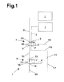
- FIG. 1 shows a section of a block diagram of a hydraulic system according to the invention, which is designated by 1 in its generality.
- the hydraulic system 1 is used, inter alia, the cooling and lubrication of a first clutch 2 and a second clutches 3 of a dual-clutch transmission, not shown.
- the first clutch 2 and the second clutch 3 is preceded by a switching valve 4.
- the switching valve 4 is connected via a line 5 to the first clutch 2 and via a line 6 to the second clutch 3.
- the switching valve 4 is a 4/2-way valve having a first and second input 7, 8 and a first and second output 9, 10 are formed.
- the line 5 connects the first output 9 of the switching valve 4 to the first clutch 2, while the line 6 connects the second output 10 with the second clutch 3.
- a control valve 11 is connected upstream, which is designed as a 2/3-way valve with an input 12 and an output 13.
- a line 14 connects the output 13 of the control valve 11 to the second input 8 of the switching valve 4.
- An aperture 15, which is connected upstream of the first input 7 of the switching valve 4, ensures a constant volume flow in a line 16, so far in front of the aperture 15 in the supply line 17 a constant pressure prevails.
- the line 16 connects the aperture 15 to the first input 7 of the change-over valve 4.
- the volume flow in the line 16 is referred to below as a lubrication flow.
- Figure 1 shows the switching valve 4 in a spring-loaded rest position, which should correspond to a first position of the switching valve 4.
- the changeover valve 4 in the first position connects the outlet 13 of the control valve 11 with the second clutch 3 and the supply line 17 or the line 16 with the first clutch 2.
- the switching valve By applying a signal via a signal line 18, the switching valve can be switched to a second position, in which the control valve 11 is connected to the first clutch 2 and the line 16 to the second clutch 3.
- the control valve 11 can occupy three positions: In a first position (shown in Figure 1) is connected between input 12 and output 13, a diaphragm 19, which ensures a certain volume flow in the line 14, when in front of the control valve 11 in a supply line 20th a constant pressure prevails. In a second position input 12 and output 13 are separated from each other, with the result that in line 14, no coolant or lubricant flows preferably in the form of an oil. In the third position of the control valve 11 input 12 and output 13 are connected without orifice or the like, which leads at a given pressure in the supply line 20 to a maximum volume flow in the line 14.
- a different volume flow sets in the line 14, which is to be referred to here as a cooling flow.
- a time averaged cooling flow can be set, which is between 0 l / min and the above-mentioned maximum flow in the line 14. If the control valve is actuated at a sufficiently high frequency, a uniform cooling flow lying between zero and a maximum value in the line 14 thus arises.
- the control valve 11 is switched by applying a current I. With a current I equal to zero, a spring 21 presses the control valve 11 in the first position. This means that in the event of a fault in the activation of the control valve 11, which leads to a failure of the current I, a specific volume flow or cooling flow dependent on the orifice 19 is ensured. At a maximum current I Max , as it could be given in the event of a short circuit, the control valve 11 is switched to the third position, in which a maximum cooling flow occurs.
- variable cooling flow can be directed to the first clutch 2 or the second clutch 3, while the constant lubrication flow in the conduit 16 is conducted accordingly to the respective other clutch.
- the two clutches 2, 3 are cooled and lubricated exclusively by means of the flows through the line 14 (cooling flow) and through the line 16 (lubricating flow), for example, in the first position of the switching valve 4, the lubricating flow corresponds to a first volume flow in the line 5, the first clutch 3 cools and lubricates.
- the cooling flow in the line 14 is a second volume flow in the conduit 6, which cools and lubricates the second clutch 3.
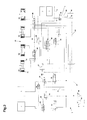
- Figure 2 shows the detail of Figure 1 in modified form with other parts of the hydraulic system 1.
- the detail of Figure 1 is arranged on the right side of Figure 2, wherein the control valve 11, the aperture 15 and the associated leads 17, 20 not are shown.
- the hydraulic system 1 comprises, in addition to the subsystem shown in FIG. 1 for cooling and lubricating the first and second clutches 2, 3, a first pressure regulator 23 and a second pressure regulator 24.
- the pressure regulators 23, 24 provide modeled pressures through which either the first and second pressure regulators second clutch 2, 3 or one of the four shift actuators A1 to A4 can be actuated.
- a switching valve 25 is arranged between the first pressure regulator 23 and the first clutch 2, .
- the modeled pressure of the pressure regulator 23 can be placed either on the first clutch 2 or a changeover switch 26 which is connected via a line 27 to a switching system 28 to which the already mentioned shift actuators A1 to A4 belong.
- a switching valve 29 is connected between the second clutch 3 and the second pressure regulator 24, which either the pressure regulated by the pressure regulator 24 to the second clutch 3 or the switch 26 sets.
- the switch 26 Depending on the input side applied pressures of the switch 26 either a connection between the switching valve 25 and the switching system 28 or a connection between the switching valve 29 and the switching system 28 ago.
- the switching valve 25 is switched by a control pressure supplied through a control line 30.
- the control line 30 connects the switching valve 25 with a signal element 31, which is controlled by electro-magnetic. It can be seen that the control pressure of the signal element 31 is also switched to the changeover valve 4 via a line 32.
- the switching valve 29 is associated with a control pressure generating signal element 33 which is connected via a signal line 34 to the switching valve 29. Via a signal line 35, the control pressure of the signal element 33 is guided to the changeover valve 4. As can be seen from FIG. 2, the control pressure of the signaling element 33 ensures that the changeover valve 4 is pressed into its first position, while the control pressure of the signal element 31 presses the changeover valve 4 against the force of the spring 22 in its second position.
- the switching valve 4 is controlled by a control pressure, which is generated by a further signal element, namely a signal element 36.
- the signal element 36 is connected via a line 37 to the switching valve 4.
- the signal element 35 switches via a line 38 two chamber selection valves 39, 40 which are arranged between the shift actuators A1 to A4 and the line 27.
- an actuator selection valve 43 and a group selection valve 44 are provided.
- the pressure in the line 27 is directed either by the group selection valve 44 either to the actuators A1 and A2 or to the actuators A3 and A4.
- the group selection valve 44 is driven by the same control signal, namely by the control pressure of the signal element 31, whereby a signal element can be saved.
- a motor-driven pump 45 with a main pressure regulator 46 provides an operating pressure which is applied via a distribution system 47 on the input side, for example, to the pressure regulators 23, 24 or also to the input 12 of the control valve 11 (see FIG. 1).
- both switching valve 25 and switching valve 29 are in the positions shown in Figure 2, the pressures of the pressure regulator 23, 24 are passed to the clutches 2, 3.
- the clutches 2, 3 can each transmit a torque depending on the modeled pressures, whereby a certain torque overlap is possible, which is necessary for cross-fading the torque from one to the other partial transmission of the dual-clutch transmission.
- the line 27 is depressurized via the changeover valves 25, 29.
- no control pressures of the signal elements 31, 33 so that the switching valve 4 can be actuated solely by the signal element 36.
- the signal element 36 the variable cooling flow in the line 14 or the constant lubricating flow in the line 16 can be arbitrarily distributed to the clutches 2, 3, for example by means of a rapid back and forth as described above.
- a gear When a gear is to be engaged, for example, a gear that can be engaged by one of the Heidelbergaktuatoren A1, A2, which belong to one of the first clutch associated first partial transmission, the switching valve 25 is brought into its second position by a control pressure of the signal element 31.
- the first clutch 2 is thus depressurized and opens.
- the control pressure of the signal element 31 is also due to the connection via the line 32 to the switching valve 4 and pushes it in its second position.
- the cooling flow in the line 14 is directed to the first clutch 2.
- the cooling flow can now be lowered to 0 l / min, so that caused by the coolant Drag torque in the first clutch 2 is significantly reduced.
- Engaging a gear is simplified.
- the system 1 simplifies the shifting of a gear by the shift actuators A3 and A4, which belong to a second partial transmission of the dual-clutch transmission.
- the second clutch 3 is depressurized, wherein applied to the switching valve 29 and the switching valve 4, the control pressure of the signal element 33.
- the control pressure pushes the switching valve 4 in its first position, regardless of the signal element 36, since the control pressure of the signal element 33 is greater than the control pressure of the signal element 36.
- the variable and zeroable cooling stream is now passed to the second clutch 3, whereby a shift actuator A3, A4 without drag torque in the second clutch 3 can engage a gear.
- FIG 3 shows a modified embodiment of the invention, which differs from the embodiment of Figure 1 in that the control valve 11 is formed as a 3/3-way valve.
- the 3/3-way valve 11 has two inputs 12a, 12b.
- a shutter is connected between the input 12a and the output 13, while the input 12b is disconnected from the output 13.
- both inputs 12a, 12b are separated from the output 13.
- the 3/3-way valve allows an unobstructed flow between the input 12b and the output 13, while the input 12a and output 13 are separated from each other.
Abstract
Description
Die Erfindung betrifft ein hydraulisches System zur Bereitstellung von Drücken und Volumenströmen in einem Doppelkupplungsgetriebe, insbesondere zur Bereitstellung eines ersten Volumenstroms zur Kühlung und Schmierung einer ersten Kupplung und zur Bereitstellung eines zweiten Volumenstroms zur Kühlung und Schmierung einer zweiten Kupplung. Neben der Kühlung und Schmierung der Kupplungen übernimmt das hydraulische System bei aus dem Stand der Technik bekannten Doppelkupplungsgetrieben noch weitere Aufgaben. So lassen sich durch das hydraulische System die beiden Kupplungen automatisch betätigen und auch das Ein-/Auslegen von Gängen des Doppelkupplungsgetriebes erfolgt über mehrere Schaltaktuatoren automatisch.The invention relates to a hydraulic system for providing pressures and volume flows in a dual-clutch transmission, in particular for providing a first volume flow for cooling and lubricating a first clutch and for providing a second volume flow for cooling and lubricating a second clutch. In addition to the cooling and lubrication of the couplings, the hydraulic system takes on other tasks in known from the prior art dual-clutch transmissions. Thus, the two clutches can be actuated automatically by the hydraulic system and also the engagement / disengagement of gears of the dual-clutch transmission takes place automatically via a plurality of shift actuators.
In der EP 1413803 ist ein Verfahren zum Kühlen der zwei Kupplungen eines Doppelkupplungsgetriebes in einem Kraftfahrzeug beschrieben. Zur Durchführung des Verfahrens wird dabei ein hydraulisches System benötigt, durch das für jede Kupplung ein ÖI-Volumenstrom bereitgestellt wird. Das Verfahren sieht dabei vor, für die jeweilige Kupplung einen Volumenstrom bereitzustellen, der von einer Ölsumpftemperatur, von der Temperatur des aus der jeweiligen Kupplung strömenden Öls und von der Leistung abhängt, die durch die Kupplungen übertragen wird. Entsprechend muss für jeden Volumenstrom ein Regelventil oder dergleichen vorgesehen sein, um in Abhängigkeit der oben genannten Faktoren die Volumenströme regeln zu können.In EP 1413803 a method for cooling the two clutches of a dual-clutch transmission in a motor vehicle is described. To carry out the method, a hydraulic system is required by which an oil volume flow is provided for each coupling. In this case, the method provides for the respective clutch to provide a volume flow which depends on an oil sump temperature, on the temperature of the oil flowing out of the respective clutch and on the power transmitted by the clutches. Accordingly, a control valve or the like must be provided for each volume flow in order to be able to regulate the volume flows as a function of the factors mentioned above.
In der DE 103 06 895 wird ebenfalls ein Verfahren zum Kühlen einer Doppelkupplung eines Kraftfahrzeugs beschrieben, wobei hier die beiden Kupplungen mit einem einzigen Volumenstrom eines Kühlmittels gemeinsam beaufschlagt werden. Dies vereinfacht im Vergleich zu einer Kühlung mit zwei Volumenströmen den Aufbau des entsprechenden hydraulischen Systems. Jedoch ist es nicht möglich, eine Kupplung des Doppelkupplungsgetriebes individuell zu kühlen und zu schmieren. So wird in der DE 103 06 895 vorgeschlagen, den Gesamtvolumenstrom zur Kühlung und Schmierung insbesondere bei niedrigen Temperaturen zu unterbrechen, um das Schleppmoment, bedingt durch das in der Kupplung befindliche Kühlmittel, zu reduzieren und somit das Einlegen eines Ganges zu vereinfachen. Dabei würde es ausreichen, nur den Volumenstrom für die Kupplung zu unterbrechen, die dem Teilgetriebe des Doppelkupplungsgetriebes zugeordnet ist, in dem ein Gang eingelegt werden soll.In DE 103 06 895 a method for cooling a double clutch of a motor vehicle is also described, in which case the two clutches are acted upon together with a single volume flow of a coolant. This simplifies the construction of the corresponding hydraulic system in comparison to cooling with two volume flows. However, it is not possible to individually cool and lubricate a clutch of the dual clutch transmission. Thus, DE 103 06 895 proposes the total volume flow for cooling and To interrupt lubrication, especially at low temperatures, in order to reduce the drag torque, due to the coolant in the clutch, and thus to simplify the engagement of a gear. It would be sufficient to interrupt only the flow for the clutch, which is assigned to the partial transmission of the dual clutch transmission, in which a gear is to be engaged.
Die Bereitstellung von Volumenströmen für jeweils eine Kupplung ermöglicht somit eine gezielte Kühlung und Schmierung der beiden Kupplungen mit mehr Freiheitsgraden. Dies führt jedoch in der Regel zu einer höheren Anzahl von hydraulischen Bauteilen und insbesondere zu einer höheren Anzahl von teuren Regelventilen. Zudem ist bei der Auslegung des hydraulischen Systems zu beachten, dass bei Ausfall eines oder mehrerer seiner Bauteile zumindest ein Notbetrieb des Doppelkupplungsgetriebes möglich sein sollte.The provision of volume flows for one clutch thus enables targeted cooling and lubrication of the two clutches with more degrees of freedom. However, this usually leads to a higher number of hydraulic components and in particular to a higher number of expensive control valves. In addition, it should be noted in the design of the hydraulic system that should one or more of its components fail, at least one emergency operation of the dual-clutch transmission should be possible.
Der Erfindung liegt daher die Aufgabe zugrunde, ein hydraulisches System zur Bereitstellung von Volumenströmen und Drücken in einem Doppelkupplungsgetriebe, insbesondere zur Schmierung und Kühlung der beiden Kupplungen des Doppelkupplungsgetriebes bereitzustellen, das einfach aufgebaut ist, kostengünstig herstellbar ist und auch bei Ausfall eines seiner Bauteile die für den Betrieb des Doppelkupplungsgetriebes notwendigen Drücke und Volumenströme weiterhin bereitstellt.The invention is therefore an object of the invention to provide a hydraulic system for the provision of volume flows and pressures in a dual clutch transmission, in particular for lubrication and cooling of the two clutches of the dual clutch transmission, which is simple, inexpensive to produce and even in case of failure of one of its components for the operation of the dual-clutch transmission still provides necessary pressures and flow rates.
Die der Erfindung zugrunde liegende Aufgabe wird dadurch gelöst, dass der ersten und zweiten Kupplung wenigstens ein Umschaltventil vorgeschaltet ist, das in einer ersten Stellung einen Schmierstrom auf die erste Kupplung und einen Kühlstrom auf die zweite Kupplung lenkt und in einer zweiten Stellung den Schmierstrom auf die zweite Kupplung und den Kühlstrom auf die erste Kupplung lenkt. Dabei trägt der Schmierstrom in der ersten Stellung zum ersten Volumenstrom bei, der für die Kühlung und Schmierung der ersten Kupplung eingesetzt wird, während in der zweiten Stellung des Umschaltventils der Kühlstrom zur Kühlung und Schmierung der ersten Kupplung verwendet wird. Dies gilt analog auch für die zweite Kupplung: Der zweite Volumenstrom zur Kühlung und Schmierung der zweiten Kupplungen wird entweder von dem Kühlstrom oder von dem Schmierstrom gespeist. Dies bedeutet, dass beispielsweise bei Ausfall des Kühlstroms oder des Schmierstroms beide Kupplungen grundsätzlich weiterhin gekühlt und geschmiert werden können, indem das Umschaltventil in die jeweils benötigte Stellung geschaltet wird. Als Kühl- und Schmiermittel wird vorzugsweise Öl verwendet.The object underlying the invention is achieved in that the first and second clutch at least one switching valve is connected upstream, which directs a lubrication flow to the first clutch and a cooling flow to the second clutch in a first position and in a second position the lubrication flow to the directs second clutch and the cooling flow to the first clutch. In this case, the lubrication flow in the first position contributes to the first volume flow which is used for the cooling and lubrication of the first clutch, while in the second position of the reversing valve, the cooling flow is used for cooling and lubrication of the first clutch. This also applies analogously to the second clutch: The second volume flow for cooling and lubrication of the second clutches is fed either by the cooling flow or by the lubricating flow. This means that, for example in case of failure of the cooling flow or the lubricating flow both clutches can be basically cooled and lubricated by the switching valve is switched to the required position. As a coolant and lubricant oil is preferably used.
Lässt sich hingegen das Umschaltventil nicht mehr schalten, wird eine Kupplung nur noch mit dem Schmierstrom und die andere Kupplung nur noch mit dem Kühlstrom geschmiert und gekühlt. Wenn Kühl- und Schmierstrom so ausgelegt sind, dass sie für sich allein genommen eine ausreichende Kühlung und Schmierung einer Kupplung gewährleisten, ist ein Betrieb des Doppelkupplungsgetriebes auch bei nicht mehr schaltbarem Umschaltventil weiterhin möglich. Erst wenn das Umschaltventil und der Kühlstrom oder der Schmierstrom gleichzeitig ausfallen, kann eine der beiden Kupplungen nicht mehr gekühlt und geschmiert werden.On the other hand, if the change-over valve can no longer be switched, one clutch will only be lubricated with the lubricant flow and the other clutch will only be lubricated with the cooling flow and cooled. If cooling and lubrication currents are designed so that they ensure sufficient cooling and lubrication of a clutch on its own, operation of the dual-clutch transmission is still possible even with a reversible switching valve. Only when the changeover valve and the cooling flow or the lubrication flow fail at the same time, one of the two clutches can no longer be cooled and lubricated.
Vorzugsweise entspricht die Summe aus dem ersten und zweiten Volumenstrom zur Kühlung und Schmierung der ersten und zweiten Kupplung der Summe aus dem Kühlstrom und dem Schmierstrom. Damit werden die Volumenströme zum Kühlen und Schmieren der beiden Kupplungen ausschließlich aus dem Schmierstrom oder dem Kühlstrom gespeist. Dies bedeutet, dass beispielsweise in der ersten Stellung des Umschaltventils die zweite Kupplung nur durch den Kühlstrom gekühlt und geschmiert wird. Das gesamte Kühl- und Schmiermittel zum Kühlen und Schmieren der Kupplungen wird somit über das Umschaltventil geführt.The sum of the first and second volume flow for cooling and lubrication of the first and second clutch preferably corresponds to the sum of the cooling flow and the lubricating flow. Thus, the flow rates for cooling and lubricating the two clutches are fed exclusively from the lubricating stream or the cooling stream. This means that, for example, in the first position of the changeover valve, the second clutch is cooled and lubricated only by the cooling flow. The entire coolant and lubricant for cooling and lubricating the clutches is thus guided via the switching valve.
In einem bevorzugten Ausführungsbeispiel ist dem Umschaltventil ein Steuerventil vorgeschaltet, das den Kühlstrom regelt. Durch das Steuerventil ist der Kühlstrom in Grenzen variierbar. Vorzugsweise kann der Volumenstrom in einem Bereich von 0 I pro Minute bis zum einem Maximalwert, beispielsweise 20 I pro Minute, variiert werden.In a preferred embodiment, the switching valve is preceded by a control valve which regulates the cooling flow. By the control valve, the cooling flow is variable within limits. Preferably, the volume flow can be varied in a range from 0 l per minute to a maximum value, for example 20 l per minute.
Vorzugsweise ist bei Nichtanliegen eines Signals, durch das das Steuerventil angesteuert wird, der Kühlstrom von Null verschieden. Dies stellt sicher, dass das Steuerventil auch einen Kühlstrom zulässt, wenn beispielsweise die das Signal führende Leitung zum Steuerventil unterbrochen ist oder wenn das das Signal erzeugende Signalelement ausgefallen ist. Folglich steht somit ein erster und zweiter Volumenstrom zur Kühlung und Schmierung der Kupplungen auch bei Ausfall des Signals für das Steuerventil weiterhin zur Verfügung, da der Kühlstrom jeweils auf beide Kupplungen gelenkt werden kann.Preferably, in the absence of a signal by which the control valve is driven, the cooling flow is different from zero. This ensures that the control valve also allows a cooling flow when, for example, the signal leading line to the control valve is interrupted or when the signal generating Signal element has failed. Consequently, therefore, a first and second flow for cooling and lubrication of the couplings is also available in case of failure of the signal for the control valve, since the cooling flow can be directed to both clutches.
Das Steuerventil ist vorzugsweise als 2/3-Wegeventil mit einem Eingang und mit einem Ausgang ausgebildet. In einer ersten Stellung des Steuerventils wird zwischen Eingang und Ausgang eine Blende geschaltet, die einen bestimmten Volumenstrom zwischen Eingang und Ausgang des Steuerventils zulässt. In einer zweiten Stellung des Steuerventils werden Eingang und Ausgang getrennt. Dadurch wird der Kühlstrom auf Null gesetzt. In einer dritten Stellung werden Eingang und Ausgang verbunden, so dass das Kühlmittel oder Öl ungehindert durch das Steuerventil fließen kann und sich ein maximaler Kühlstrom einstellt. Das 2/3-Wegeventil ist dabei so ausgelegt, dass bei einem Signalwert gleich Null die erste Stellung eingenommen wird. Dies kann beispielsweise durch eine Feder realisiert werden, die das Wegeventil bei nicht anliegendem Signal in diese erste Stellung drückt. Alternativ können die Funktionen des Steuerventils auch durch ein 3/3 Wegeventil mit zwei gebrückten Eingängen realisiert werden.The control valve is preferably designed as a 2/3-way valve with an input and an output. In a first position of the control valve between the input and output a shutter is switched, which allows a certain volume flow between the input and output of the control valve. In a second position of the control valve input and output are disconnected. This will set the cooling flow to zero. In a third position input and output are connected so that the coolant or oil can flow freely through the control valve and sets a maximum cooling flow. The 2/3-way valve is designed so that at a signal value equal to zero, the first position is taken. This can be realized, for example, by a spring which presses the directional control valve when the signal is not present in this first position. Alternatively, the functions of the control valve can also be realized by a 3/3 way valve with two bridged inputs.
In einem bevorzugten Ausführungsbeispiel ist das 2/3-Wegeventil zwischen dessen Stellungen mehrmals pro Sekunde umschaltbar. Wenn beispielsweise zwischen der zweiten und dritten Stellung hin- und hergeschaltet wird, ergibt sich ein über die Zeit gemittelter Kühlstrom, der zwischen Null und dem maximalen Kühlstrom liegt. Durch das Verhältnis der Schaltzeiten, also der Zeiten, in denen sich das Steuerventil jeweils in der zweiten oder dritten Stellung befindet, kann ein beliebiger (Mittel-)Wert für den Kühlstrom eingestellt werden. Ist beispielsweise das Verhältnis der Schaltzeit der zweiten Stellung zu der Schaltzeit der dritten Stellen 1:1 und wird ein maximaler Kühlstrom von 20 l/min angenommen, ergibt sich ein mittlerer Kühlstrom von 10 l/min.In a preferred embodiment, the 2/3-way valve between its positions several times per second switchable. For example, when switching back and forth between the second and third positions, there is a time averaged cooling flow that is between zero and the maximum cooling flow. By the ratio of the switching times, ie the times in which the control valve is in each case in the second or third position, an arbitrary (average) value for the cooling flow can be set. If, for example, the ratio of the switching time of the second position to the switching time of the third positions is 1: 1 and a maximum cooling flow of 20 l / min is assumed, this results in a mean cooling flow of 10 l / min.
Vorzugsweise kann dem Umschaltventil eine Blende vorgeschaltet werden, durch die der Schmierstrom auf einen konstanten Wert einstellbar ist. Somit liegt, da die Ausfallwahrscheinlichkeit einer Blende sehr gering ist, immer dann ein Schmierstrom vor, wenn ein Druck vor der Blende gegeben ist, der vorzugsweise durch einen Hauptdruckregler des Doppelkupplungsgetriebes geregelt wird.Preferably, the switching valve can be preceded by a diaphragm, through which the lubricating flow is adjustable to a constant value. Thus, since the probability of failure of a shutter is very low, there is always a lubrication flow, when a pressure is given in front of the diaphragm, which is preferably controlled by a main pressure regulator of the dual-clutch transmission.
In einem bevorzugten Ausführungsbeispiel ist das Umschaltventil mehrmals pro Sekunde, vorzugsweise bis zu 20 mal pro Sekunde, zwischen der ersten und zweiten Stellung umschaltbar. Dadurch, dass das Umschaltventil zwischen erster und zweiter Stellung mit einer bestimmten Frequenz hin- und herschaltet, kann der variable Kühlstrom und der Schmierstrom auf die erste und zweite Kupplung beliebig aufgeteilt werden. Durch das Zusammenwirken des schnell schaltbaren Umschaltventils und des Steuerventils für den Kühlstrom lassen sich die Volumenströme für die beiden Kupplungen in weiten Grenzen variieren. Wenn beispielsweise das Umschaltventil zwischen erster und zweiter Stellung hin- und herschaltet und die Schaltzeit, in der das Umschaltventil in der ersten Stellung verharrt, der Schaltzeit entspricht, in der das Umschaltventil in der zweiten Stellung verharrt, ergeben sich gleichgroße Volumenströme für die erste und zweite Kupplung. Wird das Verhältnis der Schaltzeiten anders eingestellt, lässt sich das Verhältnis des ersten und zweiten Volumenstroms entsprechend variieren und regeln. Wenn beispielsweise beim Hin- und Herschalten die Schaltzeit der ersten Stellung doppelt so groß ist wie die Schaltzeit der zweiten Stellung, wird der ersten Kupplung ein Volumenstrom zugeführt, der sich aus zwei Teilen Schmierstrom und einem Teil Kühlstrom zusammensetzt.In a preferred embodiment, the switching valve is switchable several times per second, preferably up to 20 times per second, between the first and second positions. Characterized in that the switching valve between first and second position with a certain frequency back and forth, the variable cooling flow and the lubrication flow can be divided as desired to the first and second clutch. Due to the interaction of the fast-switching change-over valve and the control valve for the cooling flow, the volume flows for the two clutches can be varied within wide limits. For example, when the switching valve toggles between the first and second positions and the switching time in which the switching valve remains in the first position corresponds to the switching time in which the switching valve remains in the second position, equal volumetric flows result for the first and second Clutch. If the ratio of the switching times is set differently, the ratio of the first and second volume flow can be varied and regulated accordingly. For example, when switching back and forth, the switching time of the first position is twice as large as the switching time of the second position, the first clutch, a volume flow is supplied, which is composed of two parts lubricating flow and a part of cooling flow.
In einem bevorzugten Ausführungsbeispiel ist das Umschaltventil durch ein Signal wenigstens eines Signalelements ansteuerbar, das für die Auswahl eines Schaltaktuator, für die Auswahl einer Gruppe von Schaltaktuatoren aus einer Mehrzahl von Schaltaktuatoren im Doppelkupplungsgetriebe oder für die Auswahl einer Kammer eines Schaltaktuators verwendet wird. Beispielsweise lässt sich zum Schalten des Umschaltventils ein Signalelement verwenden, das, wenn es ein Signal erzeugt, die Schaltaktuatoren zum Ein-/Auslegen der Gänge eines ersten Teilgetriebes auswählt. Durch das entsprechende Signal wird ebenfalls das Umschaltventil angesteuert und in die zweite Stellung geschaltet, so dass die erste Kupplung, die dem ersten Teilgetriebe zugeordnet ist, mit dem variablen Kühlstrom beaufschlagt wird. Um ein leichtes Einlegen der Gänge in dem ersten Teilgetriebe zu gewährleisten, wird der Kühlstrom auf Null gesetzt, so dass in der ersten Kupplung das Schleppmoment, hervorgerufen durch das in der ersten Kupplung befindlichem Öl, reduziert oder auf Null gesetzt wird. Somit kann auf ein gesondertes Signalelement für das Umschaltventil verzichtet werden, in dem die besonderen Zusammenhänge in der Schaltlogik des hydraulischen Systems in dem Doppelkupplungsgetriebe ausgenutzt werden.In a preferred embodiment, the switching valve is actuated by a signal of at least one signal element used for selecting a shift actuator, for selecting a group of shift actuators from a plurality of shift actuators in the dual clutch transmission, or for selecting a chamber of a shift actuator. For example, can be used to switch the switching valve, a signal element that, when it generates a signal, selects the shift actuators for engaging / disengaging the gears of a first sub-transmission. By the corresponding signal, the switching valve is also controlled and switched to the second position, so that the first clutch, which is assigned to the first partial transmission, is acted upon by the variable cooling flow. In order to ensure easy engagement of the gears in the first partial transmission, the cooling flow is set to zero, so that in the first clutch, the drag torque, caused is reduced or zeroed by the oil in the first clutch. Thus, it is possible to dispense with a separate signal element for the switching valve, in which the special relationships in the switching logic of the hydraulic system in the dual-clutch transmission are utilized.
Grundsätzlich ließe sich zum Schalten des Umschaltventils auch ein beliebiges Signalelement verwenden, dem in dem hydraulischen System bereits eine andere Verwendung zukommt. Es ist in diesem Fall nur sicherzustellen, dass dieses betreffende Signalelement zum Schalten des Umschaltventils nur in den Zeiten zum Einsatz kommt, in denen es für die andere Verwendung nicht gebraucht wird.In principle, it would also be possible to use an arbitrary signal element for switching the changeover valve, which already has another use in the hydraulic system. In this case, it is only necessary to ensure that this relevant signal element for switching the changeover valve is used only in the times in which it is not needed for the other use.
Es ist auch möglich, dass das Umschaltventil durch ein Signal wenigstens eines Signalelements ansteuerbar ist, durch das die erste oder die zweite Kupplung drucklos geschaltet werden kann. Führt beispielsweise das Signal eines Signalelements dazu, dass die erste Kupplung drucklos geschaltet wird, kann dieses Signal dazu verwendet werden, das Umschaltventil in dessen zweite Stellung zu schalten Dies führt dazu, dass die drucklos geschaltete Kupplung mit dem variablen Kühlstrom beaufschlagt wird, der auf den Wert Null gesetzt werden kann. Wie oben bereits beschrieben könnten dann die Gänge des ersten Teilgetriebes leicht eingelegt werden, da das Schleppmoment in der ersten Kupplung reduziert ist.It is also possible that the switching valve can be controlled by a signal of at least one signal element, by which the first or the second clutch can be depressurized. If, for example, the signal of a signal element causes the first clutch to be depressurized, this signal can be used to switch the changeover valve to its second position. This results in the unpressurized clutch being subjected to the variable cooling flow which is applied to the first clutch Value zero can be set. As already described above, the gears of the first partial transmission could then be easily inserted, since the drag torque in the first clutch is reduced.
In einem bevorzugten Ausführungsbeispiel kann das Umschaltventil durch Signale wenigstens eines Signalelements zur Schaltaktuatoren-Auswahl und wenigstens eines Signalelementes zur Drucklos-Schaltung einer der Schaltkupplungen angesteuert werden, wobei das Signal des Signalelements zur Drucklos-Schaltung der Kupplung stärker ist als das Signal des Signalelements zur Schaltaktuatoren-Auswahl. Sind beispielsweise beiden Kupplungen nicht drucklos geschaltet, liegt an dem Umschaltventil kein Signal zur Drucklos-Schaltung der Kupplung(en) an. In diesem Fall kann durch das Signalelement zur Schaltaktuatoren-Auswahl das Umschaltventil beliebig unter der Voraussetzung hin- und hergeschaltet werden, dass in diesem Schaltzustand der beiden Kupplungen eine Schaltaktuatoren-Auswahl nicht vorgesehen ist. Der Begriff "Schaltaktuator-Auswahl" in diesem Zusammenhang soll auch die Auswahl einer Kammer eines Schaltaktuators beinhalten. Dieser kann als doppeltwirkender Schaltzylinder mit zwei Kammern ausgebildet sein.In a preferred embodiment, the switching valve can be controlled by signals of at least one signal element for Schaltaktuatoren selection and at least one signal element for pressure-less switching of one of the clutches, the signal of the signal element for pressure-less switching of the clutch is stronger than the signal of the signal element to Schaltaktuatoren -Selection. If, for example, both clutches are not depressurized, there is no signal for the pressure-free connection of the clutch (s) at the changeover valve. In this case, the changeover valve can be switched back and forth as desired by the signal element for switching actuator selection, provided that a shift actuator selection is not provided in this switching state of the two clutches. The term "shift actuator selection" in this context should also the Selection of a chamber of a Schaltaktuators include. This can be designed as a double-acting switching cylinder with two chambers.
Liegt jedoch ein Signal eines Signalelements zur Drucklos-Schaltung einer Kupplung an, hat das Signal des Signalelements zur Schaltaktuatoren-Auswahl keinen Einfluss auf die Stellung des Umschaltventils.However, if a signal of a signal element for pressure-less switching of a clutch, the signal of the signal element for switching actuator selection has no influence on the position of the switching valve.
Das Umschaltventil ist vorzugsweise durch wenigstens ein Hydraulikelement ansteuerbar, durch das die Kraftregelung für die Schaltaktuatoren durchführbar ist. Dadurch kann auf ein gesondertes Bauteil zur Erzeugung eines Signals zur Ansteuerung des Umschaltventils verzichtet werden.The switching valve is preferably controlled by at least one hydraulic element, through which the force control for the shift actuators is feasible. This makes it possible to dispense with a separate component for generating a signal for controlling the switching valve.
Anhand der in den Figuren dargestellten Ausführungsbeispielen wird die Erfindung näher erläutert. Es zeigen:
Figur 1- einen Ausschnitt eines Blockschaltbilds eines ersten Ausführungsbeispiels der Erfindung;
Figur 2- ein Blockschaltbild eines anderen Ausführungsbeispiels der Erfindung; und
Figur 3- ein modifiziertes Ausführungsbeispiel
- FIG. 1
- a section of a block diagram of a first embodiment of the invention;
- FIG. 2
- a block diagram of another embodiment of the invention; and
- FIG. 3
- a modified embodiment
Figur 1 zeigt einen Ausschnitt eines Blockschaltbilds eines erfindungsgemäßen hydraulischen Systems, das in seiner Allgemeinheit mit 1 bezeichnet wird. Das hydraulische System 1 dient unter anderem der Kühlung und Schmierung einer ersten Kupplung 2 und einer zweiten Kupplungen 3 eines nicht weiter dargestellten Doppelkupplungsgetriebes.FIG. 1 shows a section of a block diagram of a hydraulic system according to the invention, which is designated by 1 in its generality. The
Der ersten Kupplung 2 und der zweiten Kupplung 3 ist ein Umschaltventil 4 vorgeschaltet. Das Umschaltventil 4 ist über eine Leitung 5 mit der ersten Kupplung 2 und über eine Leitung 6 mit der zweiten Kupplung 3 verbunden. Das Umschaltventil 4 ist als 4/2-Wegeventil mit einem ersten und zweiten Eingang 7, 8 und mit einem ersten und zweiten Ausgang 9, 10 ausgebildet. Die Leitung 5 verbindet den ersten Ausgang 9 des Umschaltventils 4 mit der ersten Kupplung 2, während die Leitung 6 den zweiten Ausgang 10 mit der zweiten Kupplung 3 verbindet.The
Dem zweiten Eingang 8 des Umschaltventils 4 ist ein Steuerventil 11 vorgeschaltet, das als 2/3-Wegeventil mit einem Eingang 12 und einem Ausgang 13 ausgebildet ist. Eine Leitung 14 verbindet den Ausgang 13 des Steuerventils 11 mit dem zweiten Eingang 8 des Umschaltventils 4. Eine Blende 15, die dem ersten Eingang 7 des Umschaltventils 4 vorgeschaltet ist, sorgt für einen konstanten Volumenstrom in einer Leitung 16, soweit vor der Blende 15 in der Zuleitung 17 ein konstanter Druck herrscht. Die Leitung 16 verbindet die Blende 15 mit dem ersten Eingang 7 des Umschaltventils 4. Der Volumenstrom in der Leitung 16 wird im folgenden als Schmierstrom bezeichnet.The
Figur 1 zeigt das Umschaltventil 4 in einer federbeaufschlagten Ruhestellung, die einer ersten Stellung des Umschaltventils 4 entsprechen soll. Wie der Darstellung zu entnehmen ist, verbindet das Umschaltventil 4 in der ersten Stellung den Ausgang 13 des Steuerventils 11 mit der zweiten Kupplung 3 und die Zuleitung 17 beziehungsweise die Leitung 16 mit der ersten Kupplung 2.Figure 1 shows the switching
Durch Anlegen eines Signals über eine Signalleitung 18 lässt sich das Umschaltventil in eine zweite Stellung schalten, bei der das Steuerventil 11 mit der ersten Kupplung 2 und die Leitung 16 mit der zweiten Kupplung 3 verbunden ist.By applying a signal via a
Das Steuerventil 11 kann drei Stellungen einnehmen: In einer ersten Stellung (in Figur 1 dargestellt) ist zwischen Eingang 12 und Ausgang 13 eine Blende 19 geschaltet, die für einen bestimmten Volumenstrom in der Leitung 14 sorgt, wenn vor dem Steuerventil 11 in einer Zuleitung 20 ein konstanter Druck herrscht. In einer zweiten Stellung werden Eingang 12 und Ausgang 13 voneinander mit der Folge getrennt, dass in Leitung 14 kein Kühl- oder Schmiermittel vorzugsweise in Form eines Öls fließt. In der dritten Stellung des Steuerventils 11 werden Eingang 12 und Ausgang 13 ohne Blende oder dergleichen verbunden, was bei einem gegebenen Druck in der Zuleitung 20 zu einem maximalen Volumenstrom in der Leitung 14 führt.The
Je nach Stellung des Steuerventils 11 stellt sich in der Leitung 14 ein unterschiedlicher Volumenstrom ein, der hier als Kühlstrom bezeichnet werden soll. Durch Hin-und Herschalten zwischen beispielsweise der zweiten und dritten Stellung des Steuerventils 11 lässt sich ein zeitlich gemittelter Kühlstrom einstellen, der zwischen 0 I/min und dem oben bereits erwähnten maximalen Volumenstrom in der Leitung 14 liegt. Wird das Steuerventil mit einer genügend hohen Frequenz betätigt, stellt sich somit ein gleichmäßiger, zwischen Null und einem Maximalwert liegender Kühlstrom in der Leitung 14 ein.Depending on the position of the
Das Steuerventil 11 wird durch Anlegen eines Stromes I geschaltet. Bei einem Strom I gleich Null drückt eine Feder 21 das Steuerventil 11 in die erste Stellung. Dies bedeutet, dass bei einem Fehler in der Ansteuerung des Steuerventils 11, der zu einem Ausfall des Stromes I führt, ein bestimmter, von der Blende 19 abhängiger Volumenstrom oder Kühlstrom gewährleistet ist. Bei einem maximalen Strom IMax, wie er bei einem Kurzschluss gegeben sein könnte, wird das Steuerventil 11 in die dritte Stellung geschaltet, in der sich ein maximaler Kühlstrom einstellt.The
Je nach Stellung des Umschaltventils 4 lässt sich der variable Kühlstrom auf die erste Kupplung 2 oder die zweite Kupplung 3 leiten, während der konstante Schmierstrom in der Leitung 16 entsprechend auf die jeweils andere Kupplung geleitet wird. Da die beiden Kupplungen 2, 3 ausschließlich mittels der Ströme durch die Leitung 14 (Kühlstrom) und durch die Leitung 16 (Schmierstrom) gekühlt und geschmiert werden, entspricht beispielsweise in der ersten Stellung des Umschaltventils 4 der Schmierstrom einem ersten Volumenstrom in der Leitung 5, der die erste Kupplung 3 kühlt und schmiert. Entsprechend stellt der Kühlstrom in der Leitung 14 einen zweiten Volumenstrom in der Leitung 6 dar, der die zweite Kupplung 3 kühlt und schmiert.Depending on the position of the change-over
Die in der Figur 1 dargestellte Bereitstellung von Volumenströmen zum Kühlen und Schmieren der Kupplungen 2 und 3 ist (eingeschränkt) funktionsfähig auch beim Ausfall einzelner Bauteile oder Signale. Fällt das durch die Signalleitung 18 zugeführte Signal aus, lässt sich das Umschaltventil 4 nicht mehr schalten. Eine Feder 22 sorgt dafür, dass in diesem Fall die in der Figur 1 dargestellte erste Stellung eingenommen wird. Sind der Kühlstrom durch die Leitung 14 und der Schmierstrom durch die Leitung 16 ausreichend groß, werden beide Kupplungen 2, 3 weiterhin gekühlt und geschmiert, so dass zumindest ein Notbetrieb möglich ist. Fällt der Strom I für das Steuerventil 11 aus, schaltet das Steuerventil 11 aufgrund der Feder 21 in seine erste Stellung, wodurch ein bestimmter Kühlstrom durch die Blende 19 zum Umschaltventil 4 gelangt.The provision of volume flows for cooling and lubricating the
Durch schnelles Hin- und Herschalten des Umschaltventils 4 lässt sich der variable Kühlstrom aus dem Steuerventil 11 und der durch die Blende 15 vorgegebene Schmierstrom auf die beiden Kupplungen 2, 3 zu gleichen Teilen aufteilen. Auch ist es möglich, durch unterschiedlich große Schaltzeiten eine entsprechende Gewichtung vorzunehmen: Beispielsweise könnte beim Hin- und Herschalten das Umschaltventil zwei Zeiteinheiten in der ersten Stellung und eine Zeiteinheit in der zweiten Stellung verweilen. Der erste Volumenstrom zur Kühlung und Schmierung der ersten Kupplung 2 würde sich dann im Mittel aus zwei Teilen Schmierstrom und einem Teil Kühlstrom zusammensetzen.By rapid switching back and forth of the switching
Figur 2 zeigt den Ausschnitt der Figur 1 in modifizierter Form mit weiteren Teilen des hydraulischen Systems 1. Der Ausschnitt der Figur 1 ist auf der rechten Seite der Figur 2 angeordnet, wobei das Steuerventil 11, die Blende 15 und die dazugehörigen Zuleitungen 17, 20 nicht dargestellt sind.Figure 2 shows the detail of Figure 1 in modified form with other parts of the
Das hydraulische System 1 umfasst neben dem in Figur 1 gezeigten Teilsystem zum Kühlen und Schmieren der ersten und zweiten Kupplung 2, 3 einen ersten Druckregler 23 und einen zweiten Druckregler 24. Die Druckregler 23, 24 stellen modellierte Drücke bereit, durch die entweder die erste und zweite Kupplung 2, 3 oder einer der vier Schaltaktuatoren A1 bis A4 betätigt werden können. Zwischen dem ersten Druckregler 23 und der ersten Kupplung 2 ist ein Umschaltventil 25 angeordnet. Durch dieses Umschaltventil 25 lässt sich der modellierte Druck des Druckreglers 23 entweder auf die erste Kupplung 2 oder einen Umschalter 26 legen, der über eine Leitung 27 mit einem Schaltsystem 28 verbunden ist, zu dem die bereits erwähnten Schaltaktuatoren A1 bis A4 gehören.The
In ähnlicher Weise ist zwischen der zweiten Kupplung 3 und dem zweiten Druckregler 24 ein Umschaltventil 29 geschaltet, was entweder den von Druckregler 24 geregelten Druck auf die zweite Kupplung 3 oder den Umschalter 26 legt. In Abhängigkeit der eingangsseitig anliegenden Drücken stellt der Umschalter 26 entweder eine Verbindung zwischen dem Umschaltventil 25 und dem Schaltsystem 28 oder eine Verbindung zwischen dem Umschaltventil 29 und dem Schaltsystem 28 her.Similarly, a switching
Das Umschaltventil 25 wird durch einen Steuerdruck geschaltet, der durch eine Steuerleitung 30 zugeführt wird. Die Steuerleitung 30 verbindet das Umschaltventil 25 mit einem Signalelement 31, das elektro-magnetisch angesteuert wird. Zu erkennen ist, das über eine Leitung 32 der Steuerdruck des Signalelements 31 auch auf das Umschaltventil 4 geschaltet wird.The switching
Auch dem Umschaltventil 29 ist ein einen Steuerdruck erzeugendes Signalelement 33 zugeordnet, das über eine Signalleitung 34 mit dem Umschaltventil 29 verbunden ist. Über eine Signalleitung 35 wird der Steuerdruck des Signalelements 33 zum Umschaltventil 4 geführt. Wie der Figur 2 zu entnehmen ist, sorgt der Steuerdruck des Signalements 33 dafür, dass das Umschaltventil 4 in dessen erste Stellung gedrückt wird, während der Steuerdruck des Signalelements 31 das Umschaltventil 4 gegen die Kraft der Feder 22 in dessen zweite Stellung drückt.Also, the switching
Des weiteren wird das Umschaltventil 4 durch einen Steuerdruck angesteuert, der von einem weiteren Signalelement, nämlich einem Signalelement 36, erzeugt wird. Das Signalelement 36 ist über eine Leitung 37 mit dem Umschaltventil 4 verbunden. Das Signalelement 35 schaltet über eine Leitung 38 zwei Kammerauswahlventile 39, 40, die zwischen den Schaltaktuatoren A1 bis A4 und der Leitung 27 angeordnet sind. Um eine der beiden Kammern 41, 42 eines bestimmten Schaltaktuators A1 bis A4 gezielt mit dem in der Leitung 27 herrschenden Druck bei gleichzeitiger Drucklos-Schaltung aller übrigen Kammern beaufschlagen zu können, sind des weiteren ein Aktuatorenauswahlventil 43 und eine Gruppenauswahlventil 44 vorgesehen. Dabei wird durch das Gruppenauswahlventil 44 der Druck in der Leitung 27 entweder auf die die Aktuatoren A1 und A2 oder auf die Aktuatoren A3 und A4 gelenkt. Durch das Aktuatorenauswahlventil wird je nach Stellung des Gruppenauswahlventils 44 entweder Schaltaktuator A1 oder A2 (beziehungsweise A3 oder A4) ausgewählt. Das Gruppenauswahlventil 44 wird durch das gleiche Steuersignal, nämlich durch den Steuerdruck des Signalelements 31, angesteuert, wodurch ein Signalelement eingespart werden kann.Furthermore, the switching
Eine motorbetriebene Pumpe 45 mit einem Hauptdruckregler 46 stellt einen Betriebsdruck bereit, der über eine Verteilungssystem 47 beispielsweise eingangsseitig an den Druckreglern 23, 24 oder auch an dem Eingang 12 des Steuerventils 11 (siehe Figur 1) anliegt.A motor-driven
Wenn sich sowohl Umschaltventil 25 als auch Umschaltventil 29 in den in Figur 2 dargestellten Stellungen befinden, werden die Drücke der Druckregler 23, 24 auf die Kupplungen 2, 3 geleitet. Die Kupplungen 2, 3 können jeweils in Abhängigkeit der modellierten Drücke ein Drehmoment übertragen, wodurch eine gewisse Drehmomentüberschneidung möglich ist, die zum Überblenden des Drehmomentes von einem auf das andere Teilgetriebe des Doppelkupplungsgetriebes notwendig ist. In dieser Phase ist die Leitung 27 über die Umschaltventile 25, 29 drucklos geschaltet. Auch liegen in dieser Phase keine Steuerdrücke der Signalelemente 31, 33 an, so dass das Umschaltventil 4 allein durch das Signalelement 36 betätigt werden kann. Durch das Signalelement 36 lässt sich der variable Kühlstrom in der Leitung 14 oder der konstante Schmierstrom in der Leitung 16 je nach Anforderung beliebig auf die Kupplungen 2, 3 aufteilen, beispielsweise durch ein wie oben beschriebenes schnelles Hin- und Herschalten.When both switching
Wenn ein Gang eingelegt werden soll, beispielsweise ein Gang, der durch einer der Schaltaktuatoren A1, A2 eingelegt werden kann, die zu einem der ersten Kupplung zugeordneten ersten Teilgetriebe gehören, wird durch einen Steuerdruck des Signalelements 31 das Umschaltventil 25 in dessen zweite Stellung gebracht. Die erste Kupplung 2 wird dadurch drucklos geschaltet und öffnet sich. Der Steuerdruck des Signalelements 31 liegt aufgrund der Verbindung über die Leitung 32 auch an dem Umschaltventil 4 an und drückt dieses in dessen zweite Stellung. Dadurch wird der Kühlstrom in der Leitung 14 auf die erste Kupplung 2 gelenkt. Der Kühlstrom lässt sich nun bis auf 0 l/min absenken, sodass ein durch das Kühlmittel hervorgerufenes Schleppmoment in der ersten Kupplung 2 deutlich reduziert wird. Ein Einlegen eines Ganges wird dadurch vereinfacht.When a gear is to be engaged, for example, a gear that can be engaged by one of the Schaltaktuatoren A1, A2, which belong to one of the first clutch associated first partial transmission, the switching
In analoger Weise vereinfacht das erfindungsgemäße System 1 das Schalten eines Ganges durch die Schaltaktuatoren A3 und A4, die zu einem zweiten Teilgetriebe des Doppelkupplungsgetriebes gehören. Hierzu wird die zweite Kupplung 3 drucklos geschaltet, wobei an dem Umschaltventil 29 und an dem Umschaltventil 4 der Steuerdruck des Signalelementes 33 anliegt. Der Steuerdruck drückt das Umschaltventil 4 in dessen erste Stellung und zwar unabhängig von dem Signalelement 36, da der Steuerdruck des Signalelements 33 größer ist als der Steuerdruck des Signalelements 36. Der variable und auf null absenkbare Kühlstrom wird nun auf die zweite Kupplung 3 geleitet, wodurch ein Schaltaktuator A3, A4 ohne Schleppmoment in der zweiten Kupplung 3 einen Gang einlegen kann.In an analogous manner, the
Figur 3 zeigt ein modifiziertes Ausführungsbeispiel der Erfindung, das sich von dem Ausführungsbeispiel der Figur 1 darin unterscheidet, dass das Steuerventil 11 als 3/3-Wegeventil ausgebildet ist. Das 3/3-Wegeventil 11 weist dabei zwei Eingänge 12a, 12b auf. In der ersten Stellung (in Figur 3 dargestellt) des 3/3-Wegeventils ist zwischen dem Eingang 12a und dem Ausgang 13 eine Blende geschaltet, während Eingang 12b vom Ausgang 13 getrennt ist. In der zweiten Stellung sind beide Eingänge 12a, 12b vom Ausgang 13 getrennt. In der dritten Stellung lässt das 3/3-Wegeventil einen ungehinderten Fluss zwischen dem Eingang 12b und dem Ausgang 13 zu, während Eingang 12a und Ausgang 13 voneinander getrennt sind.Figure 3 shows a modified embodiment of the invention, which differs from the embodiment of Figure 1 in that the
- 11
- Hydraulisches SystemHydraulic system
- 22
- Erste KupplungFirst clutch
- 33
- Zweite KupplungSecond clutch
- 44
- Umschaltventilswitching valve
- 55
- Leitungmanagement
- 66
- Leitungmanagement
- 77
- Erster EingangFirst entrance
- 88th
- Zweiter EingangSecond entrance
- 99
- Erster AusgangFirst exit
- 1010
- Zweiter AusgangSecond exit
- 1111
- Steuerventilcontrol valve
- 1212
- Eingangentrance
- 1313
- Ausgangoutput
- 1414
- Leitungmanagement
- 1515
- Blendecover
- 1616
- Leitungmanagement
- 1717
- Zuleitungsupply
- 1818
- Signalleitungsignal line
- 1919
- Blendecover
- 2020
- Zuleitungsupply
- 2121
- Federfeather
- 2222
- Federfeather
- 2323
- Erster DruckreglerFirst pressure regulator
- 2424
- Zweiter DruckreglerSecond pressure regulator
- 2525
- Umschaltventilswitching valve
- 2626
- Umschalterswitch
- 2727
- Leitungmanagement
- 2828
- Schaltsystemswitching system
- 2929
- Umschaltventilswitching valve
- 3030
- Steuerleitungcontrol line
- 3131
- Signalelementsignal element
- 3232
- Leitungmanagement
- 3333
- Signalelementsignal element
- 3434
- Signalleitungsignal line
- 3535
- Signalleitungsignal line
- 3636
- Signalelementsignal element
- 3737
- Signalleitungsignal line
- 3838
- Signalleitungsignal line
- 3939
- KammerauswahlventilChamber selector valve
- 4040
- KammerauswahlventilChamber selector valve
- 4141
- Kammerchamber
- 4242
- Kammerchamber
- 4343
- AktuatorauswahlventilAktuatorauswahlventil
- 4444
- GruppenauswahlventilGroup selector valve
- 4545
- Pumpepump
- 4646
- HauptdruckreglerMain pressure regulator
- 4747
- Verteilungssystemdistribution system
- 12a12a
- Eingangentrance
- 12b12b
- Eingangentrance
- A1 bis A4A1 to A4
- Schaltaktuatorenshift actuators
Claims (13)
Priority Applications (5)
| Application Number | Priority Date | Filing Date | Title |
|---|---|---|---|
| DE502004012404T DE502004012404D1 (en) | 2004-09-16 | 2004-09-16 | Dual-clutch transmission with a hydraulic system to provide pressures and flow rates |
| EP04104495A EP1637756B1 (en) | 2004-09-16 | 2004-09-16 | Double clutch transmission with an hydraulic system to provide pressures and flows |
| AT04104495T ATE505662T1 (en) | 2004-09-16 | 2004-09-16 | DUAL CLUTCH TRANSMISSION WITH A HYDRAULIC SYSTEM FOR PROVIDING PRESSURES AND VOLUME FLOWS |
| US11/216,318 US7395908B2 (en) | 2004-09-16 | 2005-08-31 | Hydraulic system for providing pressures and volumetric flows in a dual clutch transmission |
| US11/250,217 US7401689B2 (en) | 2004-09-16 | 2005-10-14 | Hydraulic system providing pressure and volume flows in a double-clutch transmission |
Applications Claiming Priority (1)
| Application Number | Priority Date | Filing Date | Title |
|---|---|---|---|
| EP04104495A EP1637756B1 (en) | 2004-09-16 | 2004-09-16 | Double clutch transmission with an hydraulic system to provide pressures and flows |
Publications (2)
| Publication Number | Publication Date |
|---|---|
| EP1637756A1 true EP1637756A1 (en) | 2006-03-22 |
| EP1637756B1 EP1637756B1 (en) | 2011-04-13 |
Family
ID=34929586
Family Applications (1)
| Application Number | Title | Priority Date | Filing Date |
|---|---|---|---|
| EP04104495A Not-in-force EP1637756B1 (en) | 2004-09-16 | 2004-09-16 | Double clutch transmission with an hydraulic system to provide pressures and flows |
Country Status (4)
| Country | Link |
|---|---|
| US (2) | US7395908B2 (en) |
| EP (1) | EP1637756B1 (en) |
| AT (1) | ATE505662T1 (en) |
| DE (1) | DE502004012404D1 (en) |
Cited By (10)
| Publication number | Priority date | Publication date | Assignee | Title |
|---|---|---|---|---|
| DE102006008169A1 (en) * | 2006-02-22 | 2007-08-23 | Volkswagen Ag | Device for controlling and regulating clutch cooling of gear of vehicle, particularly clutches of twin clutch transmission, is formed valve-like, where inlet and outlet are provided for coolant |
| EP1921351A1 (en) * | 2006-11-08 | 2008-05-14 | Getrag Ford Transmissions GmbH | Hydraulic control for a dual clutch automated transmission |
| WO2008055463A2 (en) * | 2006-11-08 | 2008-05-15 | Luk Lamellen Und Kupplungsbau Beteiligungs Kg | Hydraulic control for a dual clutch transmission |
| EP2019236A3 (en) * | 2007-07-23 | 2010-09-29 | LuK Lamellen und Kupplungsbau Beteiligungs KG | Double coupling drive with a device for controlling a number of hydraulic switching cylinders |
| DE102011100862A1 (en) | 2011-05-06 | 2012-11-08 | Audi Ag | Double clutch |
| DE102011100849A1 (en) | 2011-05-06 | 2012-11-08 | Audi Ag | Double clutch |
| DE102011102277A1 (en) * | 2011-05-23 | 2012-11-29 | Getrag Getriebe- Und Zahnradfabrik Hermann Hagenmeyer Gmbh & Cie Kg | Clutch assembly and powertrain for a motor vehicle |
| DE102013216285A1 (en) * | 2013-08-16 | 2015-02-19 | Schaeffler Technologies Gmbh & Co. Kg | cooling system |
| US8997958B2 (en) | 2011-05-06 | 2015-04-07 | Audi Ag | Hydraulic circuit, method for operating the same |
| CN107524733A (en) * | 2016-06-21 | 2017-12-29 | 上海汽车集团股份有限公司 | The control method and device of clutch lubrication flow |
Families Citing this family (38)
| Publication number | Priority date | Publication date | Assignee | Title |
|---|---|---|---|---|
| ATE505662T1 (en) * | 2004-09-16 | 2011-04-15 | Getrag Ford Transmissions Gmbh | DUAL CLUTCH TRANSMISSION WITH A HYDRAULIC SYSTEM FOR PROVIDING PRESSURES AND VOLUME FLOWS |
| DE112007002509B4 (en) * | 2006-10-30 | 2016-12-08 | Schaeffler Technologies AG & Co. KG | Hydraulic control for a dual-clutch transmission |
| US8443956B2 (en) * | 2008-03-04 | 2013-05-21 | Borgwarner Inc. | Dual clutch transmission having area controlled clutch cooling circuit |
| DE102008032757B4 (en) * | 2008-07-11 | 2016-03-03 | Audi Ag | Method for suppressing gear noise |
| DE102009005753A1 (en) * | 2009-01-23 | 2010-07-29 | Daimler Ag | Hydraulic control for an automated transmission |
| GB2468867A (en) * | 2009-03-24 | 2010-09-29 | Gm Global Tech Operations Inc | Device for actuating a dual clutch transmission having flow and pressure regulators |
| US8475336B2 (en) * | 2009-07-30 | 2013-07-02 | GM Global Technology Operations LLC | Hydraulic control system for a dual clutch transmission |
| US8429994B2 (en) | 2009-09-09 | 2013-04-30 | GM Global Technology Operations LLC | Hydraulic control systems for dual clutch transmissions |
| US8356529B2 (en) * | 2009-09-09 | 2013-01-22 | GM Global Technology Operations LLC | Hydraulic control systems for dual clutch transmissions |
| US8225687B2 (en) * | 2009-09-09 | 2012-07-24 | GM Global Technology Operations LLC | Hydraulic control systems for dual clutch transmissions |
| US8359941B2 (en) * | 2009-09-29 | 2013-01-29 | GM Global Technology Operations LLC | Hydraulic control systems for dual clutch transmissions |
| US8403792B2 (en) * | 2009-10-21 | 2013-03-26 | GM Global Technology Operations LLC | Hydraulic control systems for dual clutch transmissions |
| JP5379654B2 (en) * | 2009-11-13 | 2013-12-25 | 富士重工業株式会社 | Motor transmission |
| US8192176B2 (en) * | 2009-12-10 | 2012-06-05 | GM Global Technology Operations LLC | Hydraulic fluid supply system having active regulator |
| US8443687B2 (en) * | 2009-12-14 | 2013-05-21 | GM Global Technology Operations LLC | Electro-hydraulic control system for a dual clutch transmission |
| US8887498B2 (en) | 2009-12-18 | 2014-11-18 | Gm Global Technology Operations, Llc | Transmission hydraulic control system having an accumulator bypass valve assembly |
| US8402855B2 (en) * | 2010-01-11 | 2013-03-26 | GM Global Technology Operations LLC | Hydraulic control systems for dual clutch transmissions |
| US8567580B2 (en) * | 2010-01-22 | 2013-10-29 | GM Global Technology Operations LLC | Electro-hydraulic control system for a dual clutch transmission |
| US8234946B2 (en) * | 2010-02-17 | 2012-08-07 | GM Global Technology Operations LLC | Hydraulic control system for a dual clutch transmission |
| US8413777B2 (en) * | 2010-02-17 | 2013-04-09 | GM Global Technology Operations LLC | High efficiency hydraulic transmission control system |
| DE102010002747A1 (en) * | 2010-03-11 | 2011-09-15 | Zf Friedrichshafen Ag | Hydraulic system for actuating a positive switching element of a transmission device |
| US8402993B2 (en) * | 2010-05-10 | 2013-03-26 | GM Global Technology Operations LLC | Hydraulic fluid cooling system for a dual clutch automatic transmission |
| US8430220B2 (en) * | 2010-06-04 | 2013-04-30 | GM Global Technology Operations LLC | Wet dual clutch transmission control system |
| US8839928B2 (en) | 2010-12-02 | 2014-09-23 | Gm Global Technology Operations, Llc | Electro-hydraulic control system for a dual clutch transmission |
| US8904893B2 (en) * | 2010-12-06 | 2014-12-09 | Gm Global Technology Operations, Llc | Method of controlling a dual clutch transmission |
| US8733521B2 (en) * | 2010-12-06 | 2014-05-27 | Gm Global Technology Operations | Apparatus for and method of controlling a dual clutch transmission |
| US8740748B2 (en) | 2010-12-08 | 2014-06-03 | Gm Global Technology Operations, Llc | Control system and method for a dual clutch transmission |
| US8738257B2 (en) | 2010-12-08 | 2014-05-27 | Gm Global Technology Operations, Llc | Electro-hydraulic control system and method for a dual clutch transmission |
| US8702564B2 (en) | 2010-12-09 | 2014-04-22 | GM Global Technology Operations LLC | Electro-hydraulic control system and method for a dual clutch transmission |
| US8942901B2 (en) | 2010-12-09 | 2015-01-27 | Gm Global Technology Operations, Llc | Method of controlling a hydraulic control system for a dual clutch transmission |
| DE102013102415B4 (en) | 2013-03-11 | 2022-05-25 | Getrag Ford Transmissions Gmbh | Coupling device with hydraulic system |
| CN103453125B (en) * | 2013-08-30 | 2016-06-29 | 长城汽车股份有限公司 | A kind of dual-clutch transmission cooling and lubricating system |
| JP6601382B2 (en) * | 2016-12-24 | 2019-11-06 | トヨタ自動車株式会社 | Power transmission device for vehicle |
| US10443707B2 (en) * | 2017-03-24 | 2019-10-15 | Borgwarner Inc. | Cooling and lubrication system including 3-way solenoid-actuated valve for automatic transmission |
| JP2021060061A (en) * | 2019-10-04 | 2021-04-15 | マツダ株式会社 | Control device for automatic transmission |
| JP2021060062A (en) * | 2019-10-04 | 2021-04-15 | マツダ株式会社 | Control device for automatic transmission |
| EP3786487B1 (en) * | 2019-09-02 | 2022-11-09 | Mazda Motor Corporation | Control device for automatic transmission, automatic transmission, vehicle, and method of controlling automatic transmission |
| JP7451903B2 (en) * | 2019-09-02 | 2024-03-19 | マツダ株式会社 | Automatic transmission control device |
Citations (6)
| Publication number | Priority date | Publication date | Assignee | Title |
|---|---|---|---|---|
| US20020002878A1 (en) * | 2000-04-25 | 2002-01-10 | Gunther Petrzik | Hydraulic circuit for an automated twin clutch transmission for motor vehicles |
| WO2003040580A1 (en) * | 2001-11-09 | 2003-05-15 | Dr. Ing. H.C. F. Porsche Aktiengesellschaft | Drive train for a motor vehicle |
| EP1413803A2 (en) | 2002-10-25 | 2004-04-28 | BorgWarner Inc. | Dual clutch transmission clutch cooling control method |
| EP1420185A2 (en) * | 2002-11-18 | 2004-05-19 | ZF Sachs AG | Vehicle drive train comprising a pumping arrangement in order to supply a clutch device with a pressurised fluid |
| US20040112171A1 (en) * | 2001-01-12 | 2004-06-17 | Jochen Kuhstrebe | Motor vehicle comprising a drive train having a multiple clutch drive |
| DE10306895A1 (en) | 2003-02-18 | 2004-09-02 | Volkswagen Ag | Method for controlling the coolant supply of a clutch of a motor vehicle |
Family Cites Families (4)
| Publication number | Priority date | Publication date | Assignee | Title |
|---|---|---|---|---|
| US3823801A (en) * | 1973-09-07 | 1974-07-16 | Twin Disc Inc | Clutches with a fluid and cam operated pressure modulating valve |
| JPH01188723A (en) | 1988-01-22 | 1989-07-28 | Daihatsu Motor Co Ltd | Lubricator of clutch |
| JP3688752B2 (en) | 1995-04-04 | 2005-08-31 | 株式会社 神崎高級工機製作所 | Oil supply device for work vehicle |
| ATE505662T1 (en) * | 2004-09-16 | 2011-04-15 | Getrag Ford Transmissions Gmbh | DUAL CLUTCH TRANSMISSION WITH A HYDRAULIC SYSTEM FOR PROVIDING PRESSURES AND VOLUME FLOWS |
-
2004
- 2004-09-16 AT AT04104495T patent/ATE505662T1/en active
- 2004-09-16 DE DE502004012404T patent/DE502004012404D1/en active Active
- 2004-09-16 EP EP04104495A patent/EP1637756B1/en not_active Not-in-force
-
2005
- 2005-08-31 US US11/216,318 patent/US7395908B2/en active Active
- 2005-10-14 US US11/250,217 patent/US7401689B2/en active Active
Patent Citations (6)
| Publication number | Priority date | Publication date | Assignee | Title |
|---|---|---|---|---|
| US20020002878A1 (en) * | 2000-04-25 | 2002-01-10 | Gunther Petrzik | Hydraulic circuit for an automated twin clutch transmission for motor vehicles |
| US20040112171A1 (en) * | 2001-01-12 | 2004-06-17 | Jochen Kuhstrebe | Motor vehicle comprising a drive train having a multiple clutch drive |
| WO2003040580A1 (en) * | 2001-11-09 | 2003-05-15 | Dr. Ing. H.C. F. Porsche Aktiengesellschaft | Drive train for a motor vehicle |
| EP1413803A2 (en) | 2002-10-25 | 2004-04-28 | BorgWarner Inc. | Dual clutch transmission clutch cooling control method |
| EP1420185A2 (en) * | 2002-11-18 | 2004-05-19 | ZF Sachs AG | Vehicle drive train comprising a pumping arrangement in order to supply a clutch device with a pressurised fluid |
| DE10306895A1 (en) | 2003-02-18 | 2004-09-02 | Volkswagen Ag | Method for controlling the coolant supply of a clutch of a motor vehicle |
Cited By (18)
| Publication number | Priority date | Publication date | Assignee | Title |
|---|---|---|---|---|
| DE102006008169A1 (en) * | 2006-02-22 | 2007-08-23 | Volkswagen Ag | Device for controlling and regulating clutch cooling of gear of vehicle, particularly clutches of twin clutch transmission, is formed valve-like, where inlet and outlet are provided for coolant |
| DE102006008169B4 (en) * | 2006-02-22 | 2015-05-28 | Volkswagen Ag | Device for controlling and / or regulating the clutch cooling of a transmission of a motor vehicle |
| EP1921351A1 (en) * | 2006-11-08 | 2008-05-14 | Getrag Ford Transmissions GmbH | Hydraulic control for a dual clutch automated transmission |
| WO2008055463A2 (en) * | 2006-11-08 | 2008-05-15 | Luk Lamellen Und Kupplungsbau Beteiligungs Kg | Hydraulic control for a dual clutch transmission |
| WO2008055463A3 (en) * | 2006-11-08 | 2008-07-03 | Luk Lamellen & Kupplungsbau | Hydraulic control for a dual clutch transmission |
| EP2019236A3 (en) * | 2007-07-23 | 2010-09-29 | LuK Lamellen und Kupplungsbau Beteiligungs KG | Double coupling drive with a device for controlling a number of hydraulic switching cylinders |
| WO2012152397A1 (en) | 2011-05-06 | 2012-11-15 | Audi Ag | Dual clutch transmission |
| WO2012152398A1 (en) | 2011-05-06 | 2012-11-15 | Audi Ag | Dual clutch transmission |
| DE102011100849A1 (en) | 2011-05-06 | 2012-11-08 | Audi Ag | Double clutch |
| DE102011100849A8 (en) * | 2011-05-06 | 2012-12-20 | Audi Ag | Double clutch |
| US8997958B2 (en) | 2011-05-06 | 2015-04-07 | Audi Ag | Hydraulic circuit, method for operating the same |
| DE102011100862A1 (en) | 2011-05-06 | 2012-11-08 | Audi Ag | Double clutch |
| DE102011100862B4 (en) | 2011-05-06 | 2022-12-15 | Audi Ag | Double clutch |
| DE102011102277A1 (en) * | 2011-05-23 | 2012-11-29 | Getrag Getriebe- Und Zahnradfabrik Hermann Hagenmeyer Gmbh & Cie Kg | Clutch assembly and powertrain for a motor vehicle |
| US9126576B2 (en) | 2011-05-23 | 2015-09-08 | GETRAG Getriebe—und Zahnradfabrik Harmann Hagenmeyer GmbH & Cie KG | Clutch arrangement and drivetrain for a motor vehicle |
| DE102011102277B4 (en) * | 2011-05-23 | 2017-03-23 | Getrag Getriebe- Und Zahnradfabrik Hermann Hagenmeyer Gmbh & Cie Kg | Powertrain for a motor vehicle |
| DE102013216285A1 (en) * | 2013-08-16 | 2015-02-19 | Schaeffler Technologies Gmbh & Co. Kg | cooling system |
| CN107524733A (en) * | 2016-06-21 | 2017-12-29 | 上海汽车集团股份有限公司 | The control method and device of clutch lubrication flow |
Also Published As
| Publication number | Publication date |
|---|---|
| US20060054442A1 (en) | 2006-03-16 |
| US7395908B2 (en) | 2008-07-08 |
| US7401689B2 (en) | 2008-07-22 |
| ATE505662T1 (en) | 2011-04-15 |
| EP1637756B1 (en) | 2011-04-13 |
| DE502004012404D1 (en) | 2011-05-26 |
| US20060054447A1 (en) | 2006-03-16 |
Similar Documents
| Publication | Publication Date | Title |
|---|---|---|
| EP1637756B1 (en) | Double clutch transmission with an hydraulic system to provide pressures and flows | |
| EP1400733B1 (en) | Hydraulic control apparatus of a double clutch gearbox | |
| EP1596104B1 (en) | Control device for a plurality of shift cylinders and hydraulic supply system for a dual clutch transmission | |
| EP1635091B1 (en) | Hydraulic control apparatus for an automated twin clutch transmission | |
| DE102006016397B4 (en) | Transmission and a method for controlling a transmission for a motor vehicle | |
| EP1961998B1 (en) | Hydraulic circuit for an automated double clutch vehicle transmission | |
| EP1645786B1 (en) | Hydraulic control apparatus and method for a gearbox with clutch | |
| EP1950463B1 (en) | Hydraulic control device for automated double clutch transmission | |
| DE102009030749B4 (en) | Automated transmission and method for operating an automated transmission | |
| WO2011015182A1 (en) | Hydraulic system for hydraulically controlling a dual clutch transmission | |
| EP1767824A1 (en) | Hydraulic controller for an automated double clutch gearbox | |
| EP1710477A1 (en) | Shift valve for a gear shift system of a transmission | |
| DE102005019516A1 (en) | Arrangement for control of several hydraulic shift cylinders and hydraulic supply system for dual clutch operated transmission unit | |
| EP1767825A1 (en) | Hydraulic controller for an automated double clutch gearbox | |
| EP2019236B1 (en) | Double clutch transmission with a device for controlling a number of hydraulic switching cylinders | |
| DE102013102415B4 (en) | Coupling device with hydraulic system | |
| EP3910215B1 (en) | Hydraulic assembly for a vehicle transmission | |
| DE102013211226A1 (en) | Operating device for e.g. friction clutch of motor car, has actuator comprising piston, which is moved in actuator direction, where actuator actuates master cylinders by movement in actuator direction and moves master cylinders | |
| EP1635092B1 (en) | Hydraulic control device for a shifting fork in a transmission | |
| DE102010001069A1 (en) | Device for activation of hydraulic switching cylinders, particularly for switching gears of dual-clutch gearbox of motor vehicle, has regulating valve and rotary slide valve downstream regulating valve | |
| DE102013219386A1 (en) | Hydraulic control device of a dual-clutch transmission | |
| DE10239915B4 (en) | Device for controlling a hydraulically actuated switching element | |
| DE102004027115A1 (en) | Hydraulic system of a transmission | |
| EP1921351B1 (en) | Hydraulic control for a dual clutch automated transmission | |
| DE602004012539T2 (en) | METHOD FOR CONTROLLING A VEHICLE GEARBOX |
Legal Events
| Date | Code | Title | Description |
|---|---|---|---|
| PUAI | Public reference made under article 153(3) epc to a published international application that has entered the european phase |
Free format text: ORIGINAL CODE: 0009012 |
|
| AK | Designated contracting states |
Kind code of ref document: A1 Designated state(s): AT BE BG CH CY CZ DE DK EE ES FI FR GB GR HU IE IT LI LU MC NL PL PT RO SE SI SK TR |
|
| AX | Request for extension of the european patent |
Extension state: AL HR LT LV MK |
|
| 17P | Request for examination filed |
Effective date: 20060922 |
|
| AKX | Designation fees paid |
Designated state(s): AT BE BG CH CY CZ DE DK EE ES FI FR GB GR HU IE IT LI LU MC NL PL PT RO SE SI SK TR |
|
| RTI1 | Title (correction) |
Free format text: DOUBLE CLUTCH TRANSMISSION WITH AN HYDRAULIC SYSTEM TO PROVIDE PRESSURES AND FLOWS |
|
| GRAP | Despatch of communication of intention to grant a patent |
Free format text: ORIGINAL CODE: EPIDOSNIGR1 |
|
| GRAS | Grant fee paid |
Free format text: ORIGINAL CODE: EPIDOSNIGR3 |
|
| GRAA | (expected) grant |
Free format text: ORIGINAL CODE: 0009210 |
|
| AK | Designated contracting states |
Kind code of ref document: B1 Designated state(s): AT BE BG CH CY CZ DE DK EE ES FI FR GB GR HU IE IT LI LU MC NL PL PT RO SE SI SK TR |
|
| REG | Reference to a national code |
Ref country code: GB Ref legal event code: FG4D Free format text: NOT ENGLISH |
|
| REG | Reference to a national code |
Ref country code: CH Ref legal event code: EP |
|
| REG | Reference to a national code |
Ref country code: IE Ref legal event code: FG4D Free format text: LANGUAGE OF EP DOCUMENT: GERMAN |
|
| REF | Corresponds to: |
Ref document number: 502004012404 Country of ref document: DE Date of ref document: 20110526 Kind code of ref document: P |
|
| REG | Reference to a national code |
Ref country code: DE Ref legal event code: R096 Ref document number: 502004012404 Country of ref document: DE Effective date: 20110526 |
|
| REG | Reference to a national code |
Ref country code: NL Ref legal event code: VDEP Effective date: 20110413 |
|
| PG25 | Lapsed in a contracting state [announced via postgrant information from national office to epo] |
Ref country code: SE Free format text: LAPSE BECAUSE OF FAILURE TO SUBMIT A TRANSLATION OF THE DESCRIPTION OR TO PAY THE FEE WITHIN THE PRESCRIBED TIME-LIMIT Effective date: 20110413 Ref country code: PT Free format text: LAPSE BECAUSE OF FAILURE TO SUBMIT A TRANSLATION OF THE DESCRIPTION OR TO PAY THE FEE WITHIN THE PRESCRIBED TIME-LIMIT Effective date: 20110816 |
|
| REG | Reference to a national code |
Ref country code: IE Ref legal event code: FD4D |
|
| PG25 | Lapsed in a contracting state [announced via postgrant information from national office to epo] |
Ref country code: ES Free format text: LAPSE BECAUSE OF FAILURE TO SUBMIT A TRANSLATION OF THE DESCRIPTION OR TO PAY THE FEE WITHIN THE PRESCRIBED TIME-LIMIT Effective date: 20110724 Ref country code: GR Free format text: LAPSE BECAUSE OF FAILURE TO SUBMIT A TRANSLATION OF THE DESCRIPTION OR TO PAY THE FEE WITHIN THE PRESCRIBED TIME-LIMIT Effective date: 20110714 Ref country code: FI Free format text: LAPSE BECAUSE OF FAILURE TO SUBMIT A TRANSLATION OF THE DESCRIPTION OR TO PAY THE FEE WITHIN THE PRESCRIBED TIME-LIMIT Effective date: 20110413 Ref country code: CY Free format text: LAPSE BECAUSE OF FAILURE TO SUBMIT A TRANSLATION OF THE DESCRIPTION OR TO PAY THE FEE WITHIN THE PRESCRIBED TIME-LIMIT Effective date: 20110413 Ref country code: SI Free format text: LAPSE BECAUSE OF FAILURE TO SUBMIT A TRANSLATION OF THE DESCRIPTION OR TO PAY THE FEE WITHIN THE PRESCRIBED TIME-LIMIT Effective date: 20110413 |
|
| PG25 | Lapsed in a contracting state [announced via postgrant information from national office to epo] |
Ref country code: NL Free format text: LAPSE BECAUSE OF FAILURE TO SUBMIT A TRANSLATION OF THE DESCRIPTION OR TO PAY THE FEE WITHIN THE PRESCRIBED TIME-LIMIT Effective date: 20110413 |
|
| PG25 | Lapsed in a contracting state [announced via postgrant information from national office to epo] |
Ref country code: IE Free format text: LAPSE BECAUSE OF FAILURE TO SUBMIT A TRANSLATION OF THE DESCRIPTION OR TO PAY THE FEE WITHIN THE PRESCRIBED TIME-LIMIT Effective date: 20110413 Ref country code: CZ Free format text: LAPSE BECAUSE OF FAILURE TO SUBMIT A TRANSLATION OF THE DESCRIPTION OR TO PAY THE FEE WITHIN THE PRESCRIBED TIME-LIMIT Effective date: 20110413 Ref country code: EE Free format text: LAPSE BECAUSE OF FAILURE TO SUBMIT A TRANSLATION OF THE DESCRIPTION OR TO PAY THE FEE WITHIN THE PRESCRIBED TIME-LIMIT Effective date: 20110413 |
|
| PLBE | No opposition filed within time limit |
Free format text: ORIGINAL CODE: 0009261 |
|
| STAA | Information on the status of an ep patent application or granted ep patent |
Free format text: STATUS: NO OPPOSITION FILED WITHIN TIME LIMIT |
|
| PG25 | Lapsed in a contracting state [announced via postgrant information from national office to epo] |
Ref country code: RO Free format text: LAPSE BECAUSE OF FAILURE TO SUBMIT A TRANSLATION OF THE DESCRIPTION OR TO PAY THE FEE WITHIN THE PRESCRIBED TIME-LIMIT Effective date: 20110413 Ref country code: DK Free format text: LAPSE BECAUSE OF FAILURE TO SUBMIT A TRANSLATION OF THE DESCRIPTION OR TO PAY THE FEE WITHIN THE PRESCRIBED TIME-LIMIT Effective date: 20110413 Ref country code: SK Free format text: LAPSE BECAUSE OF FAILURE TO SUBMIT A TRANSLATION OF THE DESCRIPTION OR TO PAY THE FEE WITHIN THE PRESCRIBED TIME-LIMIT Effective date: 20110413 Ref country code: PL Free format text: LAPSE BECAUSE OF FAILURE TO SUBMIT A TRANSLATION OF THE DESCRIPTION OR TO PAY THE FEE WITHIN THE PRESCRIBED TIME-LIMIT Effective date: 20110413 |
|
| 26N | No opposition filed |
Effective date: 20120116 |
|
| BERE | Be: lapsed |
Owner name: GETRAG FORD TRANSMISSIONS G.M.B.H. Effective date: 20110930 |
|
| PG25 | Lapsed in a contracting state [announced via postgrant information from national office to epo] |
Ref country code: MC Free format text: LAPSE BECAUSE OF NON-PAYMENT OF DUE FEES Effective date: 20110930 |
|
| REG | Reference to a national code |
Ref country code: CH Ref legal event code: PL |
|
| REG | Reference to a national code |
Ref country code: DE Ref legal event code: R097 Ref document number: 502004012404 Country of ref document: DE Effective date: 20120116 |
|
| PG25 | Lapsed in a contracting state [announced via postgrant information from national office to epo] |
Ref country code: IT Free format text: LAPSE BECAUSE OF FAILURE TO SUBMIT A TRANSLATION OF THE DESCRIPTION OR TO PAY THE FEE WITHIN THE PRESCRIBED TIME-LIMIT Effective date: 20110413 |
|
| PG25 | Lapsed in a contracting state [announced via postgrant information from national office to epo] |
Ref country code: BE Free format text: LAPSE BECAUSE OF NON-PAYMENT OF DUE FEES Effective date: 20110930 |
|
| PG25 | Lapsed in a contracting state [announced via postgrant information from national office to epo] |
Ref country code: LI Free format text: LAPSE BECAUSE OF NON-PAYMENT OF DUE FEES Effective date: 20110930 Ref country code: CH Free format text: LAPSE BECAUSE OF NON-PAYMENT OF DUE FEES Effective date: 20110930 |
|
| REG | Reference to a national code |
Ref country code: AT Ref legal event code: MM01 Ref document number: 505662 Country of ref document: AT Kind code of ref document: T Effective date: 20110916 |
|
| PG25 | Lapsed in a contracting state [announced via postgrant information from national office to epo] |
Ref country code: AT Free format text: LAPSE BECAUSE OF NON-PAYMENT OF DUE FEES Effective date: 20110916 |
|
| PG25 | Lapsed in a contracting state [announced via postgrant information from national office to epo] |
Ref country code: LU Free format text: LAPSE BECAUSE OF NON-PAYMENT OF DUE FEES Effective date: 20110916 |
|
| PG25 | Lapsed in a contracting state [announced via postgrant information from national office to epo] |
Ref country code: BG Free format text: LAPSE BECAUSE OF FAILURE TO SUBMIT A TRANSLATION OF THE DESCRIPTION OR TO PAY THE FEE WITHIN THE PRESCRIBED TIME-LIMIT Effective date: 20110713 |
|
| PG25 | Lapsed in a contracting state [announced via postgrant information from national office to epo] |
Ref country code: TR Free format text: LAPSE BECAUSE OF FAILURE TO SUBMIT A TRANSLATION OF THE DESCRIPTION OR TO PAY THE FEE WITHIN THE PRESCRIBED TIME-LIMIT Effective date: 20110413 |
|
| PG25 | Lapsed in a contracting state [announced via postgrant information from national office to epo] |
Ref country code: HU Free format text: LAPSE BECAUSE OF FAILURE TO SUBMIT A TRANSLATION OF THE DESCRIPTION OR TO PAY THE FEE WITHIN THE PRESCRIBED TIME-LIMIT Effective date: 20110413 |
|
| REG | Reference to a national code |
Ref country code: FR Ref legal event code: PLFP Year of fee payment: 13 |
|
| REG | Reference to a national code |
Ref country code: FR Ref legal event code: PLFP Year of fee payment: 14 |
|
| REG | Reference to a national code |
Ref country code: FR Ref legal event code: PLFP Year of fee payment: 15 |
|
| PGFP | Annual fee paid to national office [announced via postgrant information from national office to epo] |
Ref country code: DE Payment date: 20190813 Year of fee payment: 16 Ref country code: FR Payment date: 20190819 Year of fee payment: 16 |
|
| PGFP | Annual fee paid to national office [announced via postgrant information from national office to epo] |
Ref country code: GB Payment date: 20190827 Year of fee payment: 16 |
|
| REG | Reference to a national code |
Ref country code: DE Ref legal event code: R119 Ref document number: 502004012404 Country of ref document: DE |
|
| GBPC | Gb: european patent ceased through non-payment of renewal fee |
Effective date: 20200916 |
|
| PG25 | Lapsed in a contracting state [announced via postgrant information from national office to epo] |
Ref country code: DE Free format text: LAPSE BECAUSE OF NON-PAYMENT OF DUE FEES Effective date: 20210401 Ref country code: FR Free format text: LAPSE BECAUSE OF NON-PAYMENT OF DUE FEES Effective date: 20200930 |
|
| PG25 | Lapsed in a contracting state [announced via postgrant information from national office to epo] |
Ref country code: GB Free format text: LAPSE BECAUSE OF NON-PAYMENT OF DUE FEES Effective date: 20200916 |