EP1637712A2 - Gas turbine engine having improved core system - Google Patents
Gas turbine engine having improved core system Download PDFInfo
- Publication number
- EP1637712A2 EP1637712A2 EP05255497A EP05255497A EP1637712A2 EP 1637712 A2 EP1637712 A2 EP 1637712A2 EP 05255497 A EP05255497 A EP 05255497A EP 05255497 A EP05255497 A EP 05255497A EP 1637712 A2 EP1637712 A2 EP 1637712A2
- Authority
- EP
- European Patent Office
- Prior art keywords
- compressed air
- source
- gas turbine
- turbine engine
- compressor
- Prior art date
- Legal status (The legal status is an assumption and is not a legal conclusion. Google has not performed a legal analysis and makes no representation as to the accuracy of the status listed.)
- Granted
Links
Images


Classifications
-
- F—MECHANICAL ENGINEERING; LIGHTING; HEATING; WEAPONS; BLASTING
- F02—COMBUSTION ENGINES; HOT-GAS OR COMBUSTION-PRODUCT ENGINE PLANTS
- F02C—GAS-TURBINE PLANTS; AIR INTAKES FOR JET-PROPULSION PLANTS; CONTROLLING FUEL SUPPLY IN AIR-BREATHING JET-PROPULSION PLANTS
- F02C5/00—Gas-turbine plants characterised by the working fluid being generated by intermittent combustion
-
- F—MECHANICAL ENGINEERING; LIGHTING; HEATING; WEAPONS; BLASTING
- F05—INDEXING SCHEMES RELATING TO ENGINES OR PUMPS IN VARIOUS SUBCLASSES OF CLASSES F01-F04
- F05D—INDEXING SCHEME FOR ASPECTS RELATING TO NON-POSITIVE-DISPLACEMENT MACHINES OR ENGINES, GAS-TURBINES OR JET-PROPULSION PLANTS
- F05D2260/00—Function
- F05D2260/20—Heat transfer, e.g. cooling
-
- Y—GENERAL TAGGING OF NEW TECHNOLOGICAL DEVELOPMENTS; GENERAL TAGGING OF CROSS-SECTIONAL TECHNOLOGIES SPANNING OVER SEVERAL SECTIONS OF THE IPC; TECHNICAL SUBJECTS COVERED BY FORMER USPC CROSS-REFERENCE ART COLLECTIONS [XRACs] AND DIGESTS
- Y02—TECHNOLOGIES OR APPLICATIONS FOR MITIGATION OR ADAPTATION AGAINST CLIMATE CHANGE
- Y02T—CLIMATE CHANGE MITIGATION TECHNOLOGIES RELATED TO TRANSPORTATION
- Y02T50/00—Aeronautics or air transport
- Y02T50/60—Efficient propulsion technologies, e.g. for aircraft
Definitions
- the present invention relates generally to an improved gas turbine engine design and, in particular, to an improved core system which replaces the high pressure system of conventional gas turbine engines.
- a booster compressor of the gas turbine engine is utilized in a manner so as to mitigate various effects of such improved core system and thereby retain a conventional low pressure turbine design.
- a pulse detonation device produces pulses of hot gas that are of approximately the same pressure. Time averaged pressure of such pulses is similar in magnitude to the pressure generated in a typical low pressure turbine engine, but at a higher temperature than normally associated with the low pressure turbine engine. It will be understood that a constant volume combustor similarly produces pulses of high-pressure, high-temperature gas that can also be utilized in the pulse detonation type of arrangement.
- An example of a stationary constant volume combustor is disclosed in U.S. Patent 3,877,219 to Hagen, while a constant volume combustor including a rotatable element is disclosed in U.S. Patent 5,960,625 to Zdvorak, Sr.
- the core or high pressure system of the conventional gas turbine engine may be replaced with a more efficient and less complicated system involving primarily the combustor.
- the modified gas turbine engine will be able to retain the conventional low pressure turbine, as well as the conventional operability characteristics thereof.
- a gas turbine engine having a longitudinal centerline axis therethrough including: a fan section at a forward end of the gas turbine engine including at least a first fan blade row connected to a drive shaft; a booster compressor positioned downstream of the fan section including a plurality of stages, where each stage includes a stationary compressor blade row and a rotating compressor blade row connected to the drive shaft and interdigitated with the stationary compressor blade row; and, a combustion system for producing pulses of gas having increased pressure and temperature from a fluid flow provided to an inlet thereof.
- a first source of compressed air from the booster compressor is provided to the combustion system inlet and a second source of compressed air from the booster compressor is provided to cool the combustion system, where the pressure of the compressed air from the second source has a greater pressure than that of the compressed air from the first source.
- a method of cooling a combustion system of a gas turbine engine including a booster compressor having a plurality of stages, wherein the combustion system produces pulses of gas having increased pressure and temperature from a fluid flow provided thereto is disclosed as including the steps of providing a first source of compressed air from the booster compressor to an inlet of the combustion system and providing a second source of compressed air from the booster compressor to cool the combustion system, wherein pressure of the compressed air from the second source is greater than pressure of the compressed air from the first source by a predetermined amount.
- a gas turbine engine including: a compressor at a forward end of the gas turbine engine having a plurality of stages, where each stage includes a stationary compressor blade row and a rotatable blade row connected to a drive shaft and interdigitated with the first compressor blade row; a combustion system for producing pulses of gas having increased pressure and temperature of a fluid supplied to an inlet thereof; a turbine downstream of and in flow communication with the combustion system for powering the drive shaft; and, a load connected to the drive shaft.
- a first source of compressed air from the compressor is provided to an inlet of the combustion system and a second source of compressed air from the compressor is provided to cool the combustion system, where the pressure of the compressed air from the second source has a greater pressure than that of the compressed air from the first source.
- An alternative combustion system may include a rotatable member which drives the compressor via a first drive shaft, with the turbine separately driving the load by means of a second drive shaft.
- a gas turbine engine having a longitudinal centerline axis therethrough including: a fan section at a forward end of the gas turbine engine including at least a first fan blade row connected to a drive shaft; a booster compressor positioned downstream of the fan section including a plurality of stages, each stage including a stationary compressor blade row and a rotating compressor blade row connected to the drive shaft and interdigitated with the stationary compressor blade row; a combustion system for producing pulses of gas having increased pressure and temperature from a fluid flow provided to an inlet thereof; and, a low pressure turbine downstream of and in flow communication with the combustion system which powers the drive shaft.
- a first source of compressed air from the booster compressor is provided to the combustion system inlet and a second source of compressed air from the booster compressor is provided at a forward end of the low pressure turbine so as to mitigate effects of the gas pulses thereon.
- FIG. 1 diagrammatically depicts a conventional gas turbine engine 10 (high bypass type) utilized with aircraft having a longitudinal or axial centerline axis 12 therethrough for reference purposes.
- a flow of air (represented by arrow 14) is directed through a fan section 16, with a portion thereof (represented by arrow 18) being provided to a booster compressor 20.
- a first compressed flow (represented by arrow 22) is provided to a core or high pressure system 25.
- core system 25 includes a high pressure compressor 24 which supplies a second compressed flow 26 to a combustor 28.
- combustor 28 is of the constant pressure type which is well known in the art.
- a high pressure turbine 30 is positioned downstream of combustor 28, which receives gas products (represented by arrow 32) produced by combustor 28 and extracts energy therefrom to drive high pressure compressor 24 by means of a first or high pressure drive shaft 34.
- high pressure compressor 24 not only provides second compressed flow 26 to an inlet of combustor 28, but also provides a cooling flow (represented by dashed arrow 42) to combustor 28.
- a low pressure turbine 36 is located downstream of core system 25 (i.e., high pressure turbine 30), where gas products (represented by arrow 38) flow therein and energy is extracted to drive booster compressor 20 and fan section 16 via a second or low pressure drive shaft 40. The remaining gas products (represented by arrow 41) then exit gas turbine engine 10.
- fan section 16 generally includes at least one row of fan blades connected to second drive shaft 40.
- booster compressor 20 and high pressure compressor 24 typically include a plurality of stages, where each stage of booster compressor 20 includes a stationary compressor blade row and a rotating compressor blade row connected to second drive shaft 40 and interdigitated with the stationary compressor blade row.
- gas turbine engine 44 similarly includes longitudinal centerline axis 12, air flow 14 to fan section 16, air flow 18 to booster compressor 20, and low pressure drive shaft 40 through which low pressure turbine 36 drives fan section 16 and booster compressor 20.
- Gas turbine engine 44 includes a new core system 45 which primarily involves a combustion system 46.
- Combustion system 46 which may be either a constant volume type combustor or a pulse detonation system, produces pulses of gas (represented by arrow 48) at an exit 50 having increased pressure and temperature compared to an air flow (represented by arrow 52) supplied to an inlet 54 thereof. Contrary to combustor 28 utilized in core system 25 described hereinabove, combustion system 46 does not maintain a relatively constant pressure therein.
- core system 45 operates substantially according to an ideal Humphrey cycle instead of the ideal Brayton cycle in core system 25.
- gas pulses 48 are preferably provided to a turbine nozzle 56 positioned immediately upstream of low pressure turbine 36 so as to direct their flow at an optimum orientation into low pressure turbine 36.
- combustion system 46 is stationary so that low pressure turbine 36 necessarily drives both fan section 16 and booster compressor 20 by means of drive shaft 40.
- combustion system 58 includes at least one rotatable member associated therewith which operates a first drive shaft 60 that drives booster compressor 20. Consequently, low pressure turbine 36 is able to separately drive fan section 16 via a second drive shaft 62.
- a first source 64 from booster compressor 20 provides compressed air 52 to inlet 54 of combustion systems 46 and 58
- a second source 66 from booster compressor 20 preferably provides compressed air 65 to turbine nozzle 56 in order to attenuate the pulsating nature of the combustor discharge (i.e., gas pulses 48) and reduce the temperature thereof to an acceptable level for low pressure turbine 36. In this way, any related noise is mitigated and smooth operation of gas turbine engine 44 is enabled.
- Second compressed air 65 also may be utilized to provide cooling to combustion systems 46 and 58, which may take the form of impingement and/or convection cooling. In addition, a small portion of second compressed air 65 may be used to provide improved atomization of fuel provided to combustion systems 46 and 58.
- first compressed air source 64 preferably originates from a valve or port in booster compressor 20 which is located upstream of second compressed air source 66. Since the air from second source 66 has preferably experienced more stages of booster compressor 20 than first source 64, compressed air 65 from second source 66 will necessarily have a higher pressure than compressed air 52 from first source 64. It is preferred that the pressure of compressed air 65 from second source 66 be greater than the pressure of compressed air 52 from first source 64 by at least approximately 20%. More preferably, the pressure differential between compressed air 65 of second source 66 and compressed air 52 from first source 64 is at least approximately 50%, and optimally such pressure differential is at least approximately 100%. To effect the desired pressure differential between compressed air 52 and 65 of first and second compressed air sources 64 and 66, respectively, it is preferred that first source 64 originate between adjacent stages of booster compressor 20 and that second source 66 originate at an aft end 68 of booster compressor 20.
- compressed air 65 from second source 66 provided to turbine nozzle 56 preferably has a greater pressure than gas pulses 48 provided at combustion system exit 50. In this way, such compressed air 65 is able to be introduced to combustion system 46 even though the pressure of compressed air 52 from first source 64 is increased therein.
- a heat exchanger 70 may optionally be employed in series therewith (as shown in phantom in Fig. 2).
- the maximum amount of thrust generated is believed to be approximately 30,000 pounds. Even so, the practical effects of substituting core system 45 for high pressure core system 25 of conventional gas turbine engine 10 include the simpler and more efficient operation of gas turbine engine 44. At the same time, the design and materials of conventional low pressure turbine 36 can be retained so that exotic, expensive materials can be avoided.
- the present invention also contemplates a method of cooling combustion systems 46 and 58 of gas turbine engine 44, where booster compressor 20 includes a plurality of stages and gas pulse 48 are discharged from such combustion systems.
- This method includes the steps of providing compressed air 52 from first source 64 in booster compressor 20 to combustion system 46 (or combustion system 58) and providing compressed air 65 from second source 66 in booster compressor 20 to cool such respective combustion system. It will be understood that the pressure of compressed air 65 from second source 66 is greater than the pressure of compressed air 52 from first source 64 by a predetermined amount as discussed hereinabove.
- the method further may include the steps of originating first compressed air source 64 from a first point located between adjacent stages of booster compressor 20 and originating second compressed air source 66 from a second point located downstream of the first point.
- the method more specifically involves the step of providing compressed air 65 from second source 66 to either an initial stage of low pressure turbine 36 or turbine nozzle 56 as explained herein.
- an additional step may include cooling such compressed air 65 prior to providing it to combustion systems 46 or 58 (e.g., by introducing compressed air 65 to heat exchanger 70).
- gas turbine engine 76 for use in industrial and other shaft power applications (e.g., marine or helicopter propulsion) as having a longitudinal centerline axis 78.
- gas turbine engine 76 includes a compressor 80 in flow communication with a flow of air (represented by an arrow 82).
- Compressor 80 preferably includes at least a first stationary compressor blade row and a second compressor blade row connected to a first drive shaft 84 and interdigitated with the first compressor blade row. Additional compressor blade rows may be connected to first drive shaft 84, with additional stationary compressor blade rows interdigitated therewith.
- An inlet guide vane (not shown) may be positioned at an upstream end of compressor 80 to direct air flow 82 therein.
- gas pulses 89 are preferably provided to a turbine nozzle 94 positioned immediately upstream of low pressure turbine 90 so as to direct their flow at an optimum orientation into low pressure turbine 90.
- low pressure turbine 90 necessarily drives both compressor 80 by means of first drive shaft 84 and a load 96 by means of a second drive shaft 98.
- combustion system 100 includes at least one rotatable member associated therewith which operates a first drive shaft 102 that drives compressor 80. Consequently, low pressure turbine 90 is able to separately drive load 96 via second drive shaft 98.
- a first source 104 from compressor 80 provides compressed air 106 to inlet 108 of combustion systems 88 and 100
- a second source 110 from compressor 80 preferably provides compressed air 112 to turbine nozzle 94 in order to attenuate the pulsating nature of the combustor discharge (i.e., gas pulses 89) and reduce the temperature thereof to an acceptable level for low pressure turbine 90. In this way, any related noise is mitigated and smooth operation of gas turbine engine 76 is enabled.
- Second compressed air 112 also may be utilized to provide cooling to combustion systems 88 and 100, which may take the form of impingement and/or convection cooling. In addition, a small portion of second compressed air 112 may be used to provide improved atomization of fuel provided to combustion systems 88 and 100.
- first compressed air source 104 preferably originates from a valve or port in compressor 80 which is located upstream of second compressed air source 110. Since the air from second source 110 has preferably experienced more stages of compressor 80 than first source 104, compressed air 112 from second source 110 will necessarily have a higher pressure than compressed air 106 from first source 104. It is preferred that the pressure of compressed air 112 from second source 110 be greater than the pressure of compressed air 106 from first source 104 by at least approximately 20%. More preferably, the pressure differential between compressed air 112 of second source 110 and compressed air 106 from first source 104 is at least approximately 50%, and optimally such pressure differential is at least approximately 100%. To effect the desired pressure differential between compressed air 106 and 112 of first and second compressed air sources 104 and 110, respectively, it is preferred that first source 104 originate between adjacent stages of compressor 80 and that second source 110 originate at an aft end 114 of compressor 80.
- compressed air 112 from second source 110 provided to turbine nozzle 94 preferably has a greater pressure than gas pulses 89 provided at combustion system exit 116. In this way, such compressed air 112 is able to be introduced to combustion systems 88 and 100 even though the pressure of compressed air 106 from first source 104 is increased therein.
- a heat exchanger 118 may optionally be employed in series therewith (as shown in phantom in Fig. 4).
- An alternative combustion system 100 is shown and described in Fig. 5 and includes a rotatable member which drives a first drive shaft 102 that causes compressor 80 to rotate.
- a second drive shaft 98 is separately driven by low pressure turbine 90 and connected to load 96.
- combustion systems 46, 58, 88 and 100 can be accomplished by appropriate modifications by one of ordinary skill in the art without departing from the scope of the invention.
- combustion systems 46, 58, 88 and 100 may be utilized with other types of gas turbine engines not depicted herein.
Abstract
Description
- The present invention relates generally to an improved gas turbine engine design and, in particular, to an improved core system which replaces the high pressure system of conventional gas turbine engines. A booster compressor of the gas turbine engine is utilized in a manner so as to mitigate various effects of such improved core system and thereby retain a conventional low pressure turbine design.
- It is well known that typical gas turbine engines are based on the ideal Brayton Cycle, where air is compressed adiabatically, heat is added at constant pressure, the resulting hot gas is expanded in a turbine, and heat is rejected at constant pressure. The energy above that required to drive the compression system is then available for propulsion or other work. Such gas turbine engines generally rely upon deflagrative combustion to burn a fuel/air mixture and produce combustion gas products which travel at relatively slow rates and relatively constant pressure within a combustion chamber. While engines based on the Brayton Cycle have reached a high level of thermodynamic efficiency by steady improvements in component efficiencies and increases in pressure ratio and peak temperature, further improvements are becoming increasingly more difficult to obtain.
- Although the combustors utilized in the conventional gas turbine engine are the type where pressure therein is maintained substantially constant, improvements in engine cycle performance and efficiency have been obtained by operating the engine so that the combustion occurs as a detonation in either a continuous or pulsed mode. Several pulse detonation system designs, for example, have been disclosed by the assignee of the present invention in the following patent applications: (1) "Pulse Detonation Device For A Gas Turbine Engine," having Serial No. 10/383,027; (2) "Pulse Detonation System For A Gas Turbine Engine," having Serial No. 10/405,561; (3) "Integral Pulse Detonation System For A Gas Turbine Engine" having Serial No. 10/418,859; (4) "Rotating Pulse Detonation System For A Gas Turbine Engine" having Serial No. 10/422,314; and, (5) "Rotary Pulse Detonation System With Aerodynamic Detonation Passages For Use In A Gas Turbine Engine" having Serial No. 10/803,293.
- It will be appreciated that a pulse detonation device produces pulses of hot gas that are of approximately the same pressure. Time averaged pressure of such pulses is similar in magnitude to the pressure generated in a typical low pressure turbine engine, but at a higher temperature than normally associated with the low pressure turbine engine. It will be understood that a constant volume combustor similarly produces pulses of high-pressure, high-temperature gas that can also be utilized in the pulse detonation type of arrangement. An example of a stationary constant volume combustor is disclosed in U.S. Patent 3,877,219 to Hagen, while a constant volume combustor including a rotatable element is disclosed in U.S. Patent 5,960,625 to Zdvorak, Sr.
- In this way, the core or high pressure system of the conventional gas turbine engine may be replaced with a more efficient and less complicated system involving primarily the combustor. At the same time, the modified gas turbine engine will be able to retain the conventional low pressure turbine, as well as the conventional operability characteristics thereof.
- Accordingly, it would be desirable for a practical overall architecture be developed for a gas turbine engine utilizing a pulse detonation device or a constant volume combustor in the core system to further improve overall engine efficiency. Further, it would be desirable for such architecture to incorporate a cooling system and method which mitigates the pulsing nature of the combustion discharge and reduces engine noise.
- In a first exemplary embodiment of the invention, a gas turbine engine having a longitudinal centerline axis therethrough is disclosed as including: a fan section at a forward end of the gas turbine engine including at least a first fan blade row connected to a drive shaft; a booster compressor positioned downstream of the fan section including a plurality of stages, where each stage includes a stationary compressor blade row and a rotating compressor blade row connected to the drive shaft and interdigitated with the stationary compressor blade row; and, a combustion system for producing pulses of gas having increased pressure and temperature from a fluid flow provided to an inlet thereof. A first source of compressed air from the booster compressor is provided to the combustion system inlet and a second source of compressed air from the booster compressor is provided to cool the combustion system, where the pressure of the compressed air from the second source has a greater pressure than that of the compressed air from the first source.
- In a second exemplary embodiment of the invention, a method of cooling a combustion system of a gas turbine engine including a booster compressor having a plurality of stages, wherein the combustion system produces pulses of gas having increased pressure and temperature from a fluid flow provided thereto, is disclosed as including the steps of providing a first source of compressed air from the booster compressor to an inlet of the combustion system and providing a second source of compressed air from the booster compressor to cool the combustion system, wherein pressure of the compressed air from the second source is greater than pressure of the compressed air from the first source by a predetermined amount.
- In accordance with a third embodiment of the invention, a gas turbine engine is disclosed as including: a compressor at a forward end of the gas turbine engine having a plurality of stages, where each stage includes a stationary compressor blade row and a rotatable blade row connected to a drive shaft and interdigitated with the first compressor blade row; a combustion system for producing pulses of gas having increased pressure and temperature of a fluid supplied to an inlet thereof; a turbine downstream of and in flow communication with the combustion system for powering the drive shaft; and, a load connected to the drive shaft. A first source of compressed air from the compressor is provided to an inlet of the combustion system and a second source of compressed air from the compressor is provided to cool the combustion system, where the pressure of the compressed air from the second source has a greater pressure than that of the compressed air from the first source. An alternative combustion system may include a rotatable member which drives the compressor via a first drive shaft, with the turbine separately driving the load by means of a second drive shaft.
- In accordance with a fourth embodiment of the present invention, a gas turbine engine having a longitudinal centerline axis therethrough is disclosed as including: a fan section at a forward end of the gas turbine engine including at least a first fan blade row connected to a drive shaft; a booster compressor positioned downstream of the fan section including a plurality of stages, each stage including a stationary compressor blade row and a rotating compressor blade row connected to the drive shaft and interdigitated with the stationary compressor blade row; a combustion system for producing pulses of gas having increased pressure and temperature from a fluid flow provided to an inlet thereof; and, a low pressure turbine downstream of and in flow communication with the combustion system which powers the drive shaft. A first source of compressed air from the booster compressor is provided to the combustion system inlet and a second source of compressed air from the booster compressor is provided at a forward end of the low pressure turbine so as to mitigate effects of the gas pulses thereon.
- Embodiments of the invention will now be described, by way of example, with reference to the accompanying drawings, in which:
- Fig. 1 is a diagrammatic view of a gas turbine engine configuration including a prior art core system, where a system of cooling is depicted therein;
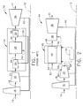
- Fig. 2 is a diagrammatic view of a gas turbine engine configuration including a core system with a stationary combustion device in accordance with the present invention, where a system of cooling is shown as being integrated therewith;
- Fig. 3 is a diagrammatic view of the gas turbine engine configuration depicted in Fig. 2 including a core system with a rotating combustion device in accordance with the present invention, where a system of cooling is shown as being integrated therewith;
- Fig. 4 is a diagrammatic view of an alternative gas turbine engine configuration including a core system with a stationary combustion device in accordance with the present invention, where a system of cooling is shown as being integrated therewith; and,
- Fig. 5 is a diagrammatic view of the gas turbine engine configuration depicted in Fig. 4 including a core system with a rotating combustion device in accordance with the present invention, where a system of cooling is shown as being integrated therewith.
- Referring now to the drawings in detail, wherein identical numerals indicate the same elements throughout the figures, Fig. 1 diagrammatically depicts a conventional gas turbine engine 10 (high bypass type) utilized with aircraft having a longitudinal or
axial centerline axis 12 therethrough for reference purposes. A flow of air (represented by arrow 14) is directed through afan section 16, with a portion thereof (represented by arrow 18) being provided to abooster compressor 20. Thereafter, a first compressed flow (represented by arrow 22) is provided to a core orhigh pressure system 25. - More specifically,
core system 25 includes ahigh pressure compressor 24 which supplies a secondcompressed flow 26 to acombustor 28. It will be understood thatcombustor 28 is of the constant pressure type which is well known in the art. Ahigh pressure turbine 30 is positioned downstream ofcombustor 28, which receives gas products (represented by arrow 32) produced bycombustor 28 and extracts energy therefrom to drivehigh pressure compressor 24 by means of a first or highpressure drive shaft 34. It will further be understood thathigh pressure compressor 24 not only provides secondcompressed flow 26 to an inlet ofcombustor 28, but also provides a cooling flow (represented by dashed arrow 42) tocombustor 28. - A
low pressure turbine 36 is located downstream of core system 25 (i.e., high pressure turbine 30), where gas products (represented by arrow 38) flow therein and energy is extracted to drivebooster compressor 20 andfan section 16 via a second or lowpressure drive shaft 40. The remaining gas products (represented by arrow 41) then exitgas turbine engine 10. It will be appreciated thatfan section 16 generally includes at least one row of fan blades connected tosecond drive shaft 40. It will also be understood thatbooster compressor 20 andhigh pressure compressor 24 typically include a plurality of stages, where each stage ofbooster compressor 20 includes a stationary compressor blade row and a rotating compressor blade row connected tosecond drive shaft 40 and interdigitated with the stationary compressor blade row. - As seen in Fig. 2,
gas turbine engine 44 similarly includeslongitudinal centerline axis 12,air flow 14 tofan section 16,air flow 18 tobooster compressor 20, and lowpressure drive shaft 40 through whichlow pressure turbine 36 drivesfan section 16 andbooster compressor 20.Gas turbine engine 44, however, includes anew core system 45 which primarily involves acombustion system 46.Combustion system 46, which may be either a constant volume type combustor or a pulse detonation system, produces pulses of gas (represented by arrow 48) at anexit 50 having increased pressure and temperature compared to an air flow (represented by arrow 52) supplied to aninlet 54 thereof. Contrary tocombustor 28 utilized incore system 25 described hereinabove,combustion system 46 does not maintain a relatively constant pressure therein. Moreover,core system 45 operates substantially according to an ideal Humphrey cycle instead of the ideal Brayton cycle incore system 25. - It will be seen that
gas pulses 48 are preferably provided to aturbine nozzle 56 positioned immediately upstream oflow pressure turbine 36 so as to direct their flow at an optimum orientation intolow pressure turbine 36. In the embodiment depicted in Fig. 2,combustion system 46 is stationary so thatlow pressure turbine 36 necessarily drives bothfan section 16 andbooster compressor 20 by means ofdrive shaft 40. In an alternative configuration depicted in Fig. 3, it will be noted thatcombustion system 58 includes at least one rotatable member associated therewith which operates afirst drive shaft 60 that drivesbooster compressor 20. Consequently,low pressure turbine 36 is able to separately drivefan section 16 via asecond drive shaft 62. - Further, it will be seen from Figs. 2 and 3 that a
first source 64 frombooster compressor 20 provides compressedair 52 to inlet 54 ofcombustion systems second source 66 frombooster compressor 20 preferably provides compressedair 65 toturbine nozzle 56 in order to attenuate the pulsating nature of the combustor discharge (i.e., gas pulses 48) and reduce the temperature thereof to an acceptable level forlow pressure turbine 36. In this way, any related noise is mitigated and smooth operation ofgas turbine engine 44 is enabled. Second compressedair 65 also may be utilized to provide cooling tocombustion systems air 65 may be used to provide improved atomization of fuel provided tocombustion systems - It will be appreciated that first compressed
air source 64 preferably originates from a valve or port inbooster compressor 20 which is located upstream of second compressedair source 66. Since the air fromsecond source 66 has preferably experienced more stages ofbooster compressor 20 thanfirst source 64, compressedair 65 fromsecond source 66 will necessarily have a higher pressure than compressedair 52 fromfirst source 64. It is preferred that the pressure of compressedair 65 fromsecond source 66 be greater than the pressure of compressedair 52 fromfirst source 64 by at least approximately 20%. More preferably, the pressure differential between compressedair 65 ofsecond source 66 and compressedair 52 fromfirst source 64 is at least approximately 50%, and optimally such pressure differential is at least approximately 100%. To effect the desired pressure differential between compressedair air sources first source 64 originate between adjacent stages ofbooster compressor 20 and thatsecond source 66 originate at anaft end 68 ofbooster compressor 20. - It will further be appreciated that compressed
air 65 fromsecond source 66 provided toturbine nozzle 56 preferably has a greater pressure thangas pulses 48 provided atcombustion system exit 50. In this way, suchcompressed air 65 is able to be introduced tocombustion system 46 even though the pressure of compressedair 52 fromfirst source 64 is increased therein. To increase the cooling effectiveness of compressedair 65 fromsecond source 66, aheat exchanger 70 may optionally be employed in series therewith (as shown in phantom in Fig. 2). - With regard to
gas turbine engine 44 and thecore system 45 utilized therein, the maximum amount of thrust generated, without additional modifications, is believed to be approximately 30,000 pounds. Even so, the practical effects of substitutingcore system 45 for highpressure core system 25 of conventionalgas turbine engine 10 include the simpler and more efficient operation ofgas turbine engine 44. At the same time, the design and materials of conventionallow pressure turbine 36 can be retained so that exotic, expensive materials can be avoided. - The present invention also contemplates a method of cooling
combustion systems gas turbine engine 44, wherebooster compressor 20 includes a plurality of stages andgas pulse 48 are discharged from such combustion systems. This method includes the steps of providingcompressed air 52 fromfirst source 64 inbooster compressor 20 to combustion system 46 (or combustion system 58) and providingcompressed air 65 fromsecond source 66 inbooster compressor 20 to cool such respective combustion system. It will be understood that the pressure ofcompressed air 65 fromsecond source 66 is greater than the pressure ofcompressed air 52 fromfirst source 64 by a predetermined amount as discussed hereinabove. The method further may include the steps of originating firstcompressed air source 64 from a first point located between adjacent stages ofbooster compressor 20 and originating secondcompressed air source 66 from a second point located downstream of the first point. The method more specifically involves the step of providingcompressed air 65 fromsecond source 66 to either an initial stage oflow pressure turbine 36 orturbine nozzle 56 as explained herein. To increase the effectiveness ofcompressed air 65 fromsecond source 66, an additional step may include cooling suchcompressed air 65 prior to providing it tocombustion systems 46 or 58 (e.g., by introducingcompressed air 65 to heat exchanger 70). - Fig. 4 depicts an alternative
gas turbine engine 76 for use in industrial and other shaft power applications (e.g., marine or helicopter propulsion) as having alongitudinal centerline axis 78. As seen therein,gas turbine engine 76 includes acompressor 80 in flow communication with a flow of air (represented by an arrow 82).Compressor 80 preferably includes at least a first stationary compressor blade row and a second compressor blade row connected to afirst drive shaft 84 and interdigitated with the first compressor blade row. Additional compressor blade rows may be connected tofirst drive shaft 84, with additional stationary compressor blade rows interdigitated therewith. An inlet guide vane (not shown) may be positioned at an upstream end ofcompressor 80 todirect air flow 82 therein. Acore system 86 having astationary combustion system 88, like that described hereinabove with respect to Fig. 2, providesgas pulses 89 to alow pressure turbine 90 that powersfirst drive shaft 84. Combustion gases (represented by an arrow 92) then exit fromlow pressure turbine 90 and are exhausted. - It will be seen that
gas pulses 89 are preferably provided to aturbine nozzle 94 positioned immediately upstream oflow pressure turbine 90 so as to direct their flow at an optimum orientation intolow pressure turbine 90. In the embodiment depicted in Fig. 4,low pressure turbine 90 necessarily drives bothcompressor 80 by means offirst drive shaft 84 and aload 96 by means of asecond drive shaft 98. In an alternative configuration depicted in Fig. 5, it will be noted thatcombustion system 100 includes at least one rotatable member associated therewith which operates afirst drive shaft 102 that drivescompressor 80. Consequently,low pressure turbine 90 is able to separately driveload 96 viasecond drive shaft 98. - Further, it will be seen from Figs. 4 and 5 that a
first source 104 fromcompressor 80 provides compressedair 106 toinlet 108 ofcombustion systems second source 110 fromcompressor 80 preferably provides compressedair 112 toturbine nozzle 94 in order to attenuate the pulsating nature of the combustor discharge (i.e., gas pulses 89) and reduce the temperature thereof to an acceptable level forlow pressure turbine 90. In this way, any related noise is mitigated and smooth operation ofgas turbine engine 76 is enabled. Secondcompressed air 112 also may be utilized to provide cooling tocombustion systems compressed air 112 may be used to provide improved atomization of fuel provided tocombustion systems - It will be appreciated that first
compressed air source 104 preferably originates from a valve or port incompressor 80 which is located upstream of secondcompressed air source 110. Since the air fromsecond source 110 has preferably experienced more stages ofcompressor 80 thanfirst source 104,compressed air 112 fromsecond source 110 will necessarily have a higher pressure thancompressed air 106 fromfirst source 104. It is preferred that the pressure ofcompressed air 112 fromsecond source 110 be greater than the pressure ofcompressed air 106 fromfirst source 104 by at least approximately 20%. More preferably, the pressure differential betweencompressed air 112 ofsecond source 110 andcompressed air 106 fromfirst source 104 is at least approximately 50%, and optimally such pressure differential is at least approximately 100%. To effect the desired pressure differential betweencompressed air compressed air sources first source 104 originate between adjacent stages ofcompressor 80 and thatsecond source 110 originate at anaft end 114 ofcompressor 80. - It will further be appreciated that
compressed air 112 fromsecond source 110 provided toturbine nozzle 94 preferably has a greater pressure thangas pulses 89 provided atcombustion system exit 116. In this way, suchcompressed air 112 is able to be introduced tocombustion systems compressed air 106 fromfirst source 104 is increased therein. To increase the cooling effectiveness ofcompressed air 112 fromsecond source 110, a heat exchanger 118 may optionally be employed in series therewith (as shown in phantom in Fig. 4). - An
alternative combustion system 100 is shown and described in Fig. 5 and includes a rotatable member which drives afirst drive shaft 102 that causescompressor 80 to rotate. Asecond drive shaft 98 is separately driven bylow pressure turbine 90 and connected to load 96. - Having shown and described the preferred embodiment of the present invention, further adaptations of
core systems combustion systems combustion systems
Claims (10)
- A gas turbine engine (44) having a longitudinal centerline axis (12) therethrough, comprising:(a) fan section (16) at a forward end of said gas turbine engine (44) including at least a first fan blade row connected to a drive shaft (40/62);(b) a booster compressor (20) positioned downstream of said fan section (16) including a plurality of stages, each said stage including a stationary compressor blade row and a rotating compressor blade row connected to a drive shaft (40/60) and interdigitated with said stationary compressor blade row; and,(c) a combustion system (46) for producing pulses of gas having increased pressure and temperature from a fluid flow (52) provided to an inlet (54) thereof;wherein a first source (64) of compressed air (52) from said booster compressor (20) is provided to said combustion system inlet (54) and a second source (66) of compressed air (65) from said booster compressor (20) is provided to cool said combustion system (46).
- The gas turbine engine (44) of claim 1, wherein compressed air (65) from said second source (66) has a higher pressure than compressed air (52) from said first source (64).
- The gas turbine engine (44) of claim 1, wherein pressure of compressed air (65) from said second source (66) is greater than pressure of compressed air (52) from said first source (64) by at least approximately 20%.
- The gas turbine engine (44) of claim 1, wherein said first source (64) of compressed air (52) originates in said booster compressor (20) upstream of said second source (66) of compressed air (65).
- The gas turbine engine (44) of claim 1, wherein said first source (64) of compressed air (52) originates between adjacent stages of said booster compressor (20).
- The gas turbine engine (44) of claim 1, wherein said second source (66) of compressed air (65) originates at an aft end (68) of said booster compressor (20).
- The gas turbine engine (44) of claim 1, wherein pressure of compressed air (65) from said second source (66) is greater than pressure of fluid (48) at an exit end (50) of said combustion system (46).
- The gas turbine engine (44) of claim 1, wherein said combustion device (46) includes at least one rotating member for powering said drive shaft (60).
- The gas turbine engine (44) of claim 1, further comprising a turbine (36) downstream of and in flow communication with said combustion system (46) which powers said drive shaft (40/62).
- The gas turbine engine (44) of claim 1, wherein said combustion system (46) includes no rotating members.
Applications Claiming Priority (1)
| Application Number | Priority Date | Filing Date | Title |
|---|---|---|---|
| US10/941,508 US7093446B2 (en) | 2004-09-15 | 2004-09-15 | Gas turbine engine having improved core system |
Publications (3)
| Publication Number | Publication Date |
|---|---|
| EP1637712A2 true EP1637712A2 (en) | 2006-03-22 |
| EP1637712A3 EP1637712A3 (en) | 2012-09-19 |
| EP1637712B1 EP1637712B1 (en) | 2014-05-21 |
Family
ID=35058586
Family Applications (1)
| Application Number | Title | Priority Date | Filing Date |
|---|---|---|---|
| EP05255497.9A Expired - Fee Related EP1637712B1 (en) | 2004-09-15 | 2005-09-08 | Gas turbine engine having improved core system |
Country Status (5)
| Country | Link |
|---|---|
| US (1) | US7093446B2 (en) |
| EP (1) | EP1637712B1 (en) |
| JP (1) | JP2006083856A (en) |
| CN (1) | CN1800610B (en) |
| CA (1) | CA2517182C (en) |
Families Citing this family (9)
| Publication number | Priority date | Publication date | Assignee | Title |
|---|---|---|---|---|
| WO2004072451A1 (en) * | 2003-02-12 | 2004-08-26 | Ishikawajima-Harima Heavy Industries Co., Ltd. | Pulse detonation engine system for driving turbine |
| US7841165B2 (en) * | 2006-10-31 | 2010-11-30 | General Electric Company | Gas turbine engine assembly and methods of assembling same |
| US20120151895A1 (en) * | 2010-12-21 | 2012-06-21 | General Electric Company | Hot gas path component cooling for hybrid pulse detonation combustion systems |
| US20130239542A1 (en) * | 2012-03-16 | 2013-09-19 | United Technologies Corporation | Structures and methods for intercooling aircraft gas turbine engines |
| US10711702B2 (en) * | 2015-08-18 | 2020-07-14 | General Electric Company | Mixed flow turbocore |
| US20170159563A1 (en) * | 2015-12-07 | 2017-06-08 | General Electric Company | Method and system for pre-cooler exhaust energy recovery |
| US10495001B2 (en) | 2017-06-15 | 2019-12-03 | General Electric Company | Combustion section heat transfer system for a propulsion system |
| FR3071545B1 (en) * | 2017-09-27 | 2019-10-11 | Safran | COMBUSTION CHAMBER WITH CONSTANT VOLUME AND COMBUSTION SYSTEM FOR ASSOCIATED TURBOMACHINE |
| CN108644015B (en) * | 2018-04-24 | 2019-07-26 | 南昌航空大学 | A kind of self-starting gas-turbine unit burnt based on detonation |
Citations (4)
| Publication number | Priority date | Publication date | Assignee | Title |
|---|---|---|---|---|
| US5381653A (en) * | 1992-12-10 | 1995-01-17 | Asea Brown Boveri Ltd. | Aircraft engine with pressure exchanger |
| EP1138922A1 (en) * | 2000-03-31 | 2001-10-04 | General Electric Company | Combined cycle pulse detonation turbine engine |
| US20030126853A1 (en) * | 2001-12-21 | 2003-07-10 | Koshoffer John Michael | Methods and apparatus for operating gas turbine engines |
| EP1435449A1 (en) * | 2002-12-30 | 2004-07-07 | United Technologies Corporation | Pulsed combustion device with distributed ignition |
Family Cites Families (37)
| Publication number | Priority date | Publication date | Assignee | Title |
|---|---|---|---|---|
| US3673802A (en) * | 1970-06-18 | 1972-07-04 | Gen Electric | Fan engine with counter rotating geared core booster |
| US3705492A (en) * | 1971-01-11 | 1972-12-12 | Gen Motors Corp | Regenerative gas turbine system |
| DE2232025A1 (en) | 1972-06-30 | 1974-01-17 | Motoren Turbinen Union | GAS TURBINE SYSTEM, IN PARTICULAR ENGINE WITH COUNTER-ROOM COMBUSTION |
| FR2210717B1 (en) * | 1973-01-16 | 1976-05-14 | Meur Henri Le | |
| US3986347A (en) * | 1973-12-06 | 1976-10-19 | Phillips Petroleum Company | Combustor process for low-level NOx and CO emissions |
| US4896499A (en) * | 1978-10-26 | 1990-01-30 | Rice Ivan G | Compression intercooled gas turbine combined cycle |
| JPS5592040U (en) * | 1978-12-21 | 1980-06-25 | ||
| US4296599A (en) * | 1979-03-30 | 1981-10-27 | General Electric Company | Turbine cooling air modulation apparatus |
| JPS59188956U (en) * | 1983-06-02 | 1984-12-14 | 三菱重工業株式会社 | jet engine |
| DE4304989A1 (en) * | 1993-02-18 | 1994-08-25 | Abb Management Ag | Process for cooling a gas turbine plant |
| US5579631A (en) * | 1994-04-28 | 1996-12-03 | Westinghouse Electric Corporation | Steam cooling of gas turbine with backup air cooling |
| JP2887445B2 (en) * | 1994-11-10 | 1999-04-26 | 千治 内藤 | 4 cycle jet type prime mover |
| JP3619599B2 (en) * | 1995-11-30 | 2005-02-09 | 株式会社東芝 | Gas turbine plant |
| US5782076A (en) * | 1996-05-17 | 1998-07-21 | Westinghouse Electric Corporation | Closed loop air cooling system for combustion turbines |
| JP2001504564A (en) * | 1996-09-26 | 2001-04-03 | シーメンス アクチエンゲゼルシヤフト | Method for compensating pressure loss caused by cooling air guide in gas turbine equipment |
| EP0949405B1 (en) * | 1998-04-07 | 2006-05-31 | Mitsubishi Heavy Industries, Ltd. | Turbine plant |
| NL1011383C2 (en) * | 1998-06-24 | 1999-12-27 | Kema Nv | Apparatus for compressing a gaseous medium and systems comprising such an apparatus. |
| US5960625A (en) | 1998-08-21 | 1999-10-05 | Zdvorak, Sr.; Edward H. | Constant volume combustion turbine with plurality flow turbine wheels |
| US6250061B1 (en) * | 1999-03-02 | 2001-06-26 | General Electric Company | Compressor system and methods for reducing cooling airflow |
| JP2000328962A (en) * | 1999-05-19 | 2000-11-28 | Mitsubishi Heavy Ind Ltd | Turbine system |
| JP3593488B2 (en) * | 2000-02-25 | 2004-11-24 | 株式会社日立製作所 | gas turbine |
| US6389793B1 (en) * | 2000-04-19 | 2002-05-21 | General Electric Company | Combustion turbine cooling media supply system and related method |
| DE10027833A1 (en) * | 2000-06-05 | 2001-12-13 | Alstom Power Nv | Method for cooling a gas turbine system and gas turbine system for carrying out the method |
| US6574966B2 (en) * | 2000-06-08 | 2003-06-10 | Hitachi, Ltd. | Gas turbine for power generation |
| DE10035676A1 (en) * | 2000-07-21 | 2002-02-07 | Siemens Ag | Gas turbine and method for operating a gas turbine |
| JP3782649B2 (en) * | 2000-08-21 | 2006-06-07 | 株式会社日立製作所 | gas turbine |
| US6298656B1 (en) * | 2000-09-29 | 2001-10-09 | Siemens Westinghouse Power Corporation | Compressed air steam generator for cooling combustion turbine transition section |
| GB2373299B (en) * | 2001-03-12 | 2004-10-27 | Alstom Power Nv | Re-fired gas turbine engine |
| ES2261288T3 (en) * | 2001-03-26 | 2006-11-16 | Siemens Aktiengesellschaft | GAS TURBINE. |
| US6487863B1 (en) * | 2001-03-30 | 2002-12-03 | Siemens Westinghouse Power Corporation | Method and apparatus for cooling high temperature components in a gas turbine |
| DE50115614D1 (en) * | 2001-04-17 | 2010-10-14 | Alstom Technology Ltd | Method for suppressing combustion fluctuations in a gas turbine |
| DE10122695A1 (en) * | 2001-05-10 | 2002-11-21 | Siemens Ag | Process for cooling a gas turbine and gas turbine plant |
| US6550253B2 (en) * | 2001-09-12 | 2003-04-22 | General Electric Company | Apparatus and methods for controlling flow in turbomachinery |
| JP4061635B2 (en) * | 2001-12-07 | 2008-03-19 | 株式会社Ihi | Turbofan engine and its operation method |
| JP2004116485A (en) * | 2002-09-30 | 2004-04-15 | Mitsubishi Heavy Ind Ltd | Cooling structure for gas turbine |
| US6829896B2 (en) * | 2002-12-13 | 2004-12-14 | Siemens Westinghouse Power Corporation | Catalytic oxidation module for a gas turbine engine |
| US6978621B2 (en) * | 2002-12-31 | 2005-12-27 | General Electric Company | Turbo recuperator device |
-
2004
- 2004-09-15 US US10/941,508 patent/US7093446B2/en not_active Expired - Fee Related
-
2005
- 2005-08-25 CA CA2517182A patent/CA2517182C/en not_active Expired - Fee Related
- 2005-09-08 EP EP05255497.9A patent/EP1637712B1/en not_active Expired - Fee Related
- 2005-09-13 JP JP2005264921A patent/JP2006083856A/en active Pending
- 2005-09-15 CN CN200510109921.2A patent/CN1800610B/en not_active Expired - Fee Related
Patent Citations (4)
| Publication number | Priority date | Publication date | Assignee | Title |
|---|---|---|---|---|
| US5381653A (en) * | 1992-12-10 | 1995-01-17 | Asea Brown Boveri Ltd. | Aircraft engine with pressure exchanger |
| EP1138922A1 (en) * | 2000-03-31 | 2001-10-04 | General Electric Company | Combined cycle pulse detonation turbine engine |
| US20030126853A1 (en) * | 2001-12-21 | 2003-07-10 | Koshoffer John Michael | Methods and apparatus for operating gas turbine engines |
| EP1435449A1 (en) * | 2002-12-30 | 2004-07-07 | United Technologies Corporation | Pulsed combustion device with distributed ignition |
Also Published As
| Publication number | Publication date |
|---|---|
| US7093446B2 (en) | 2006-08-22 |
| EP1637712A3 (en) | 2012-09-19 |
| US20060053804A1 (en) | 2006-03-16 |
| EP1637712B1 (en) | 2014-05-21 |
| CA2517182A1 (en) | 2006-03-15 |
| JP2006083856A (en) | 2006-03-30 |
| CN1800610B (en) | 2014-12-31 |
| CN1800610A (en) | 2006-07-12 |
| CA2517182C (en) | 2013-02-12 |
Similar Documents
| Publication | Publication Date | Title |
|---|---|---|
| EP1637711B1 (en) | High thrust gas turbine engine with modified core system | |
| CA2517182C (en) | Gas turbine engine having improved core system | |
| US6837683B2 (en) | Gas turbine engine aerofoil | |
| US7631484B2 (en) | High pressure ratio aft fan | |
| EP0564135B1 (en) | Gas turbine engine cooling system | |
| EP0608142B1 (en) | Gas turbine engine cooling system | |
| US20080229751A1 (en) | Cooling system for gas turbine engine having improved core system | |
| CN109028149B (en) | Variable geometry rotary detonation combustor and method of operating same | |
| CN109028142B (en) | Propulsion system and method of operating the same | |
| US8695324B2 (en) | Multistage tip fan | |
| US20110120083A1 (en) | Gas turbine engine with outer fans | |
| CN109028144B (en) | Integral vortex rotary detonation propulsion system | |
| WO2001057380A1 (en) | Variable cycle gas turbine engine | |
| JP2007182873A (en) | Thrust augmenting device and its method, and exhaust nozzle | |
| EP1471243A2 (en) | Rotating pulse detonation system for a gas turbine engine | |
| GB2382383A (en) | Gas turbine aerofoil having a longitudinal cooling arrangement | |
| US8978387B2 (en) | Hot gas path component cooling for hybrid pulse detonation combustion systems | |
| US20080127630A1 (en) | Turbine for application to pulse detonation combustion system and engine containing the turbine | |
| US20120151895A1 (en) | Hot gas path component cooling for hybrid pulse detonation combustion systems | |
| RU2405959C1 (en) | Method of gas generation for creation of thrust in air jet engine with multi-stage axial compressor and air jet engine |
Legal Events
| Date | Code | Title | Description |
|---|---|---|---|
| PUAI | Public reference made under article 153(3) epc to a published international application that has entered the european phase |
Free format text: ORIGINAL CODE: 0009012 |
|
| AK | Designated contracting states |
Kind code of ref document: A2 Designated state(s): AT BE BG CH CY CZ DE DK EE ES FI FR GB GR HU IE IS IT LI LT LU LV MC NL PL PT RO SE SI SK TR |
|
| AX | Request for extension of the european patent |
Extension state: AL BA HR MK YU |
|
| PUAL | Search report despatched |
Free format text: ORIGINAL CODE: 0009013 |
|
| AK | Designated contracting states |
Kind code of ref document: A3 Designated state(s): AT BE BG CH CY CZ DE DK EE ES FI FR GB GR HU IE IS IT LI LT LU LV MC NL PL PT RO SE SI SK TR |
|
| AX | Request for extension of the european patent |
Extension state: AL BA HR MK YU |
|
| RIC1 | Information provided on ipc code assigned before grant |
Ipc: F23C 15/00 20060101ALI20120813BHEP Ipc: F02C 5/00 20060101AFI20120813BHEP |
|
| 17P | Request for examination filed |
Effective date: 20130319 |
|
| AKX | Designation fees paid |
Designated state(s): DE FR GB SE |
|
| GRAP | Despatch of communication of intention to grant a patent |
Free format text: ORIGINAL CODE: EPIDOSNIGR1 |
|
| INTG | Intention to grant announced |
Effective date: 20140116 |
|
| GRAS | Grant fee paid |
Free format text: ORIGINAL CODE: EPIDOSNIGR3 |
|
| GRAA | (expected) grant |
Free format text: ORIGINAL CODE: 0009210 |
|
| AK | Designated contracting states |
Kind code of ref document: B1 Designated state(s): DE FR GB SE |
|
| REG | Reference to a national code |
Ref country code: GB Ref legal event code: FG4D |
|
| REG | Reference to a national code |
Ref country code: DE Ref legal event code: R096 Ref document number: 602005043694 Country of ref document: DE Effective date: 20140703 |
|
| PG25 | Lapsed in a contracting state [announced via postgrant information from national office to epo] |
Ref country code: SE Free format text: LAPSE BECAUSE OF FAILURE TO SUBMIT A TRANSLATION OF THE DESCRIPTION OR TO PAY THE FEE WITHIN THE PRESCRIBED TIME-LIMIT Effective date: 20140521 |
|
| REG | Reference to a national code |
Ref country code: DE Ref legal event code: R097 Ref document number: 602005043694 Country of ref document: DE |
|
| PLBE | No opposition filed within time limit |
Free format text: ORIGINAL CODE: 0009261 |
|
| STAA | Information on the status of an ep patent application or granted ep patent |
Free format text: STATUS: NO OPPOSITION FILED WITHIN TIME LIMIT |
|
| 26N | No opposition filed |
Effective date: 20150224 |
|
| REG | Reference to a national code |
Ref country code: DE Ref legal event code: R097 Ref document number: 602005043694 Country of ref document: DE Effective date: 20150224 |
|
| REG | Reference to a national code |
Ref country code: FR Ref legal event code: PLFP Year of fee payment: 11 |
|
| PGFP | Annual fee paid to national office [announced via postgrant information from national office to epo] |
Ref country code: GB Payment date: 20150928 Year of fee payment: 11 |
|
| PGFP | Annual fee paid to national office [announced via postgrant information from national office to epo] |
Ref country code: FR Payment date: 20150917 Year of fee payment: 11 |
|
| PGFP | Annual fee paid to national office [announced via postgrant information from national office to epo] |
Ref country code: DE Payment date: 20150929 Year of fee payment: 11 |
|
| REG | Reference to a national code |
Ref country code: DE Ref legal event code: R119 Ref document number: 602005043694 Country of ref document: DE |
|
| GBPC | Gb: european patent ceased through non-payment of renewal fee |
Effective date: 20160908 |
|
| REG | Reference to a national code |
Ref country code: FR Ref legal event code: ST Effective date: 20170531 |
|
| PG25 | Lapsed in a contracting state [announced via postgrant information from national office to epo] |
Ref country code: DE Free format text: LAPSE BECAUSE OF NON-PAYMENT OF DUE FEES Effective date: 20170401 Ref country code: FR Free format text: LAPSE BECAUSE OF NON-PAYMENT OF DUE FEES Effective date: 20160930 Ref country code: GB Free format text: LAPSE BECAUSE OF NON-PAYMENT OF DUE FEES Effective date: 20160908 |