EP1637708A2 - Device for controlling an air flap system of a motor vehicle - Google Patents
Device for controlling an air flap system of a motor vehicle Download PDFInfo
- Publication number
- EP1637708A2 EP1637708A2 EP05019289A EP05019289A EP1637708A2 EP 1637708 A2 EP1637708 A2 EP 1637708A2 EP 05019289 A EP05019289 A EP 05019289A EP 05019289 A EP05019289 A EP 05019289A EP 1637708 A2 EP1637708 A2 EP 1637708A2
- Authority
- EP
- European Patent Office
- Prior art keywords
- actuator
- switch
- measuring device
- electrical signal
- air flap
- Prior art date
- Legal status (The legal status is an assumption and is not a legal conclusion. Google has not performed a legal analysis and makes no representation as to the accuracy of the status listed.)
- Granted
Links
Images


Classifications
-
- G—PHYSICS
- G05—CONTROLLING; REGULATING
- G05D—SYSTEMS FOR CONTROLLING OR REGULATING NON-ELECTRIC VARIABLES
- G05D23/00—Control of temperature
- G05D23/19—Control of temperature characterised by the use of electric means
- G05D23/1919—Control of temperature characterised by the use of electric means characterised by the type of controller
- G05D23/1921—Control of temperature characterised by the use of electric means characterised by the type of controller using a thermal motor
-
- F—MECHANICAL ENGINEERING; LIGHTING; HEATING; WEAPONS; BLASTING
- F01—MACHINES OR ENGINES IN GENERAL; ENGINE PLANTS IN GENERAL; STEAM ENGINES
- F01P—COOLING OF MACHINES OR ENGINES IN GENERAL; COOLING OF INTERNAL-COMBUSTION ENGINES
- F01P7/00—Controlling of coolant flow
- F01P7/02—Controlling of coolant flow the coolant being cooling-air
- F01P7/10—Controlling of coolant flow the coolant being cooling-air by throttling amount of air flowing through liquid-to-air heat exchangers
- F01P7/12—Controlling of coolant flow the coolant being cooling-air by throttling amount of air flowing through liquid-to-air heat exchangers by thermostatic control
-
- B—PERFORMING OPERATIONS; TRANSPORTING
- B60—VEHICLES IN GENERAL
- B60K—ARRANGEMENT OR MOUNTING OF PROPULSION UNITS OR OF TRANSMISSIONS IN VEHICLES; ARRANGEMENT OR MOUNTING OF PLURAL DIVERSE PRIME-MOVERS IN VEHICLES; AUXILIARY DRIVES FOR VEHICLES; INSTRUMENTATION OR DASHBOARDS FOR VEHICLES; ARRANGEMENTS IN CONNECTION WITH COOLING, AIR INTAKE, GAS EXHAUST OR FUEL SUPPLY OF PROPULSION UNITS IN VEHICLES
- B60K11/00—Arrangement in connection with cooling of propulsion units
- B60K11/08—Air inlets for cooling; Shutters or blinds therefor
- B60K11/085—Air inlets for cooling; Shutters or blinds therefor with adjustable shutters or blinds
-
- F—MECHANICAL ENGINEERING; LIGHTING; HEATING; WEAPONS; BLASTING
- F01—MACHINES OR ENGINES IN GENERAL; ENGINE PLANTS IN GENERAL; STEAM ENGINES
- F01P—COOLING OF MACHINES OR ENGINES IN GENERAL; COOLING OF INTERNAL-COMBUSTION ENGINES
- F01P2025/00—Measuring
-
- F—MECHANICAL ENGINEERING; LIGHTING; HEATING; WEAPONS; BLASTING
- F01—MACHINES OR ENGINES IN GENERAL; ENGINE PLANTS IN GENERAL; STEAM ENGINES
- F01P—COOLING OF MACHINES OR ENGINES IN GENERAL; COOLING OF INTERNAL-COMBUSTION ENGINES
- F01P2070/00—Details
- F01P2070/04—Details using electrical heating elements
-
- Y—GENERAL TAGGING OF NEW TECHNOLOGICAL DEVELOPMENTS; GENERAL TAGGING OF CROSS-SECTIONAL TECHNOLOGIES SPANNING OVER SEVERAL SECTIONS OF THE IPC; TECHNICAL SUBJECTS COVERED BY FORMER USPC CROSS-REFERENCE ART COLLECTIONS [XRACs] AND DIGESTS
- Y02—TECHNOLOGIES OR APPLICATIONS FOR MITIGATION OR ADAPTATION AGAINST CLIMATE CHANGE
- Y02T—CLIMATE CHANGE MITIGATION TECHNOLOGIES RELATED TO TRANSPORTATION
- Y02T10/00—Road transport of goods or passengers
- Y02T10/80—Technologies aiming to reduce greenhouse gasses emissions common to all road transportation technologies
- Y02T10/88—Optimized components or subsystems, e.g. lighting, actively controlled glasses
Definitions
- the invention relates to a device for controlling an air flap system of a motor vehicle according to the preamble of claim 1.
- Modern cooling systems in particular for drives of motor vehicles, are increasingly subject to complex control requirements for optimizing the cooling capacity as a function of the operating state of the drive. It is desired that arranged in the range of a cooler adjustable air dampers such as slats or blinds can be adjusted defined. In particular, feedback on the position of the louvers on a control unit of the cooling system are desired.
- DE 102 23 686 A1 describes an actuator with a heated expansion element for actuating a radiator shutter or a thermostatic valve, wherein a heating circuit is interrupted in an end position of the actuator by a switch actuated by the actuator.
- the air flap system is part of a main radiator of a cooling system for an internal combustion engine of the motor vehicle, whereby an improved control of the cooling of the internal combustion engine is made possible.
- the electrical signal can be generated by means of a voltage divider from a supply voltage, whereby low production costs and high reliability are possible.
- the adjusting element is designed as an expansion element, preferably with a heating device, wherein the heating device is operable by means of the supply voltage.
- the measuring device comprises a first switch and a second switch, wherein the first switch can be actuated by reaching the first position of the actuator and the second switch by reaching the second position of the actuator.
- the positions of the actuator can be measured easily and reliably.
- at least a third switch for reading a third position of the actuator may be provided, wherein the third switch is actuated by reaching the third position of the actuator.
- the measuring device comprises a stepless measuring element, wherein in a range of movement the actuator is the position of the actuator in a dependent of their electrical signal convertible.
- a very precise control of the louvers is possible, and in particular a temporal behavior of the air damper adjustment can be determined particularly accurately.
- this advantageously comprises an adjustable electrical resistance.
- a reliable stepless measuring element can be provided by mechanical coupling of actuator and adjustable resistance.
- the measuring device and the actuator may preferably be formed as a structural unit, wherein the structural unit is connected to a control unit associated therewith by means of exactly one electrical signal line for signaling the actuator position.
- the structural unit is connected to a control unit associated therewith by means of exactly one electrical signal line for signaling the actuator position.
- the structural unit is connected to a control unit associated therewith by means of exactly one electrical signal line for signaling the actuator position.
- a different voltage of the signal line is assigned to the different readable positions of the actuator.
- the electrical signal can be read out by means of a processor-controlled control circuit.
- a processor-controlled control circuit In this way, a particularly variable control of the device or the louvers is possible, in addition, important parameters such as a temporal behavior of the actuator position can be gerümmelt in a simple manner.
- a fault diagnosis of the system in terms of cable breakage or other malfunctions can be provided in a simple manner.
- the device comprises an actuating element 1, which comprises a stationary mounted base body 1 b and a linearly movable actuator 2 on the other hand.
- the actuator 2 is connected to an air flap system, not shown, so that the linear movement of the actuator 2 causes an opening or closing movement of at least one air damper.
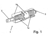
- the actuator 1 is designed as an expansion element (see Fig. 1), wherein the actuator 2 comprises a cylinder which is pushed out upon heating of an encapsulated Dehnstoffvolumens from the base body 1 b. This can be done both by an external heating of the actuating element 1 and by an energization of an actuator disposed in the electric heating element.
- the control element For contacting the heating element, the control element has a ground terminal, which corresponds to the housing and a pole 3 for connecting a supply voltage.
- the movement of the actuator 2, in particular the return movement upon cooling of the expansion material is supported by provided springs 1a.
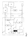
- the stroke H of the actuator 2 is shown in the schematic Fig. 2 to Fig. 4 respectively as a dotted line.
- a first switch 4 and a second switch 5 is provided.
- the switches are presently designed as mechanical switches, but also electronic switches are conceivable, which can be controlled by means of magnetic fields or light.
- the two switches 4, 5 are electrically contacted via a resistor network 6.
- the network is arranged between a ground line 7 (negative pole of a vehicle battery 9) and a line 8 supplying the supply voltage for the expansion element.
- a first node 6a of the network is connected to the ground line 7 and a second node 6b is connected to the supply voltage 8.
- a first resistor R1 and, subsequently, the first switch 4 are connected to the first node 6a.
- a third node 6c of the network follows, in which a branch into two branches takes place.
- the second switch 5 is initially arranged in series, and subsequently a second resistor R2 is arranged in series.
- a third resistor R3 is arranged in the other branch.
- the resistors R2 and R3 are connected on their side remote from the third node 6c in the second node 6b to the supply voltage 8.
- From the third node 6c also branches off a signal line 10, which is occupied according to the following description with the electrical information about the position of the actuator 2.
- the network 6 with the switches 4, 5 and its connections to the supply line 8 and ground line 7 forms a total of a measuring device, by means of which positions of the actuator 2 can be measured and converted into electrical signals.
- the adjusting element 1 and the measuring device 4, 5, 6 according to the above description are preferably formed as a common structural unit 11. This is indicated in the drawings Fig. 2 to Fig. 4 as the assembly 11 surrounding box of a dotted line.
- This unit 11 is only three electrical lines, namely the supply line 8, the ground line 7 (which must not necessarily be designed as a separate cable according to the function of the vehicle mass) and the control line 10, connected to a control unit or control circuit 12.
- the control circuit 12 comprises a processor unit 13 with a programmable microprocessor and a power output stage 14. Processor unit 13 and output stage 14 are connected to one another via a control bus 15, by means of which control and control of the output stage 14 by the processor unit 13 takes place.
- the signal line 10 is connected to the processor unit 13.
- a fourth resistor R4 is connected between signal line 10 and ground line 7.
- resistor R4 is disposed in the region of the control unit 12. In general, however, it can also be arranged in the area of the assembly 11. Regarding its function, it is part of the network 6.
- the resistors R1 to R4 are all ohmic resistors; in general, however, they can also be of complex impedance.
- R3 and R4 are about the same size.
- R1 and R2 are each significantly smaller than R3 and R4, respectively.
- the first switch 4 is actuated by the actuator and in the present case closed, whereas the arranged at the other end of Stellgliedweges second switch 5 is not actuated and open is.
- R1 is significantly smaller than R4
- the supply voltage hereinafter referred to as UV
- the battery voltage 7 is generally zero volts (0V)) at the location of the signal line in a good approximation ratio R1 to R3 divided.
- the first switch 4 is open and only the second switch 5 is actuated and closed by the actuator 2. Since R2 is significantly smaller than R3, R2 and R4 form, to a good approximation, a voltage divider and the signal voltage is 0.5 UV ⁇ US ⁇ UV.
- each of the actuator states “fully retracted” (first readable position P1), “partially extended”, and “fully extended” (second readable position P2) is associated with precisely one different voltage value US of the signal line.
- the voltage value US is in each case relative to the supply voltage UV, but this is known to the processor unit 13 via the control bus 15.
- the supply voltage UV will also not be variable in size.
- a metered heating of the expansion element 1 is rather carried out by a controlled pulsation of the supply voltage UV.
- the signal input is always at ground potential 0V, in particular regardless of how long the expansion element is energized with heating current.
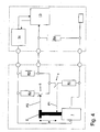
- the second embodiment according to FIG. 5 differs from the first embodiment as follows:
- a third switch 20 and a fifth resistor R5 are provided.
- the third switch 20 is connected at one end to the third node 6c.
- the fifth resistor connects the other end of the third switch 20 to the second node 6b.
- the resistors R2, R3 and R5 are thus arranged in parallel between the nodes 6b and 6c.
- the third switch 20 is actuated in a partially extended position of the actuator 2, which is present in the present example shortly before reaching the end position of the actuator 2.
- This position is a third readable position P3 of the actuator, in this position P3, the first switch 4 is opened, the second switch 5 is opened and the third switch 20 is closed.
- the fifth resistor R5 has a value different from that of the second resistor R2 but smaller than that of the third resistor R3.
- the third voltage associated signal voltage is thus greater than 0.5 UV, but smaller than the second switch 5 associated signal voltage. Overall, therefore, depending on the position of the actuator 2, four different signal voltages US before.
- the expansion element is energized with a DC voltage until the third readable position P3 is reached.
- the power amplifier begins to energize the actuator 2 with a pulsed voltage of adjustable duty cycle (PWM signal).
- PWM signal adjustable duty cycle
- the duty cycle is adjusted by the processor unit 13 so that the actuator 2 remains in the third position P3.
- a faulty control can be avoided by having readable positions P1, P2 with different voltages on both sides of the third position P3.
- the power will be increased at voltage 0.5V. Otherwise, should the actuator already be located above the third position, which would require a reduction in performance, this fault condition would soon be detected by reaching the end position (second readable position P2).
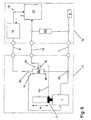
- the third embodiment according to FIG. 6 differs from the first embodiment in that the network 6 is replaced by an adjustable ohmic resistor RV.
- This has a first base terminal 30 which is connected to the ground line 7 and a second base terminal 31 which is connected to the supply line 8. Between the ground terminals 30, 31 there is a constant maximum value of the resistor RV.
- An adjustable tap 32 which may be formed as a sliding contact over a carbon track, is connected to the signal line 10.
- the resistor R4 between signal line 10 and ground line 7 in the region of the control circuit 12 is present. This can improve the fault diagnosis of the system as described above.
- the adjustable resistor RV already forms a voltage divider 6 for itself.
- the tap 32 is mechanically connected to the actuator 2 so that movement of the actuator 2 causes movement of the tap 32 above the carbon web.
- each position or position PV of the actuator 2 is assigned to a different division ratio of the voltage divider 6 and thus a different signal voltage US steplessly.
- the variable resistor RV thus forms a stepless measuring element.
- the signal voltage depends monotonically on the stroke of the actuator 2 and in particular is proportional to the stroke of the actuator. 2
- adjustable resistors may be present.
- other measuring elements such as an incremental encoder can also be used.
- a movement of the actuator 2 would be reported as a number of pulses to the processor unit 13, so that as a result stepless measurement of the actuator position is also possible.
- Such an arrangement could be realized partially or completely without a resistor network.
- the third embodiment are suitable for determining the temporal behavior of the control element 1 in response to energization by the output stage 14 or to environmental parameters (ambient temperature).
- environmental parameters ambient temperature
- Such measured parameters may in turn be incorporated into a software algorithm of the processor unit in order to allow the most optimal possible control of the air flap system and thus the cooling system of the vehicle.
Landscapes
- Engineering & Computer Science (AREA)
- Chemical & Material Sciences (AREA)
- Combustion & Propulsion (AREA)
- Mechanical Engineering (AREA)
- General Engineering & Computer Science (AREA)
- Physics & Mathematics (AREA)
- General Physics & Mathematics (AREA)
- Automation & Control Theory (AREA)
- Air-Conditioning For Vehicles (AREA)
- Cooling, Air Intake And Gas Exhaust, And Fuel Tank Arrangements In Propulsion Units (AREA)
Abstract
Description
Die Erfindung betrifft eine Vorrichtung zur Steuerung eines Luftklappensystems eines Kraftfahrzeugs nach dem Oberbegriff des Anspruchs 1.The invention relates to a device for controlling an air flap system of a motor vehicle according to the preamble of
Moderne Kühlsysteme, insbesondere für Antriebe von Kraftfahrzeugen, unterliegen zunehmend Anforderungen einer aufwendigen Steuerung zur Optimierung der Kühlleistung in Abhängigkeit des Betriebszustandes des Antriebs. Dabei ist es gewünscht, daß im Bereich eines Kühlers angeordnete verstellbare Luftklappen wie etwa Lamellen oder Jalousien definiert verstellt werden können. Insbesondere sind dabei Rückmeldungen über die Stellung der Luftklappen an eine Steuerungseinheit des Kühlsystems gewünscht.Modern cooling systems, in particular for drives of motor vehicles, are increasingly subject to complex control requirements for optimizing the cooling capacity as a function of the operating state of the drive. It is desired that arranged in the range of a cooler adjustable air dampers such as slats or blinds can be adjusted defined. In particular, feedback on the position of the louvers on a control unit of the cooling system are desired.
DE 102 23 686 A1 beschreibt ein Stellglied mit einem beheizbaren Dehnstoffelement zur Betätigung einer Kühlerjalousie oder eines Thermostatventils, wobei ein Heizstromkreis in einer Endstellung des Stellgliedes durch einen von dem Stellglied betätigten Schalter unterbrochen wird.DE 102 23 686 A1 describes an actuator with a heated expansion element for actuating a radiator shutter or a thermostatic valve, wherein a heating circuit is interrupted in an end position of the actuator by a switch actuated by the actuator.
Es ist die Aufgabe der Erfindung, eine Vorrichtung zur Steuerung eines Luftklappensystems eines Kraftfahrzeugs anzugeben, mittels derer eine Stellung der Luftklappen auf einfache Weise und zuverlässig überwacht werden kann.It is the object of the invention to provide a device for controlling an air flap system of a motor vehicle, by means of which a position of the louvers can be monitored easily and reliably.
Diese Aufgabe wird für eine eingangs genannte Vorrichtung zur Steuerung eines Luftklappensystems eines Kraftfahrzeugs erfindungsgemäß mit den kennzeichnenden Merkmalen des Anspruchs 1 gelöst.This object is achieved for an aforementioned device for controlling an air flap system of a motor vehicle according to the invention with the characterizing features of
Durch die zumindest zwei auslesbaren Positionen ist vorteilhaft eine Überwachung der Luftklappenstellung ermöglicht. wobei insbesondere eine Grundstellung vor Beginn einer Stellbewegung Stellgliedes und eine vollständig oder zumindest weitgehend ausgefahrene Position des Stellgliedes feststellbar sind.Due to the at least two readable positions monitoring of the air damper position is advantageously possible. wherein in particular a basic position before the start of an actuating movement of the actuator and a fully or at least substantially extended position of the actuator can be determined.
Vorteilhaft ist das Luftklappensystem Bestandteil eines Hauptkühlers eines Kühlsystems für einen Verbrennungsmotor des Kraftfahrzeugs, wodurch eine verbesserte Steuerung der Kühlung des Verbrennungsmotors ermöglicht ist.Advantageously, the air flap system is part of a main radiator of a cooling system for an internal combustion engine of the motor vehicle, whereby an improved control of the cooling of the internal combustion engine is made possible.
In einer vorteilhaften Ausgestaltung der Erfindung ist das elektrische Signal mittels eines Spannungsteilers aus einer Versorgungsspannung generierbar, wodurch geringe Herstellungkosten und hohe Zuverlässigkeit ermöglicht sind.In an advantageous embodiment of the invention, the electrical signal can be generated by means of a voltage divider from a supply voltage, whereby low production costs and high reliability are possible.
Weiterhin vorteilhaft ist das Stellelement als Dehnstoffelement, bevorzugt mit einer Heizeinrichtung, ausgebildet, wobei die Heizeinrichtung mittels der Versorgungsspannung betreibbar ist. Insgesamt wird dadurch ein kostengünstiges und zuverlässiges Stellelement mit einem hohen Steuerungskomfort kombiniert.Further advantageously, the adjusting element is designed as an expansion element, preferably with a heating device, wherein the heating device is operable by means of the supply voltage. Overall, this combines a cost-effective and reliable actuator with a high degree of control comfort.
Bevorzugt umfaßt die Meßvorrichtung einen ersten Schalter und einen zweiten Schalter umfaßt, wobei der erste Schalter durch Erreichen der ersten Position des Stellgliedes und der zweite Schalter durch Erreichen der zweiten Position des Stellgliedes betätigbar ist. Hierdurch können die Positionen des Stellgliedes einfach und zuverlässig gemessen werden. Je nach Anforderungen und zur weiteren Erhöhung der Steuerungsmöglichkeiten kann auch zumindest ein dritter Schalter zum Auslesen einer dritten Position des Stellgliedes vorgesehen sein, wobei der dritte Schalter durch Erreichen der dritten Position des Stellgliedes betätigbar ist.Preferably, the measuring device comprises a first switch and a second switch, wherein the first switch can be actuated by reaching the first position of the actuator and the second switch by reaching the second position of the actuator. As a result, the positions of the actuator can be measured easily and reliably. Depending on requirements and to further increase the control options and at least a third switch for reading a third position of the actuator may be provided, wherein the third switch is actuated by reaching the third position of the actuator.
In einer besonders bevorzugten Ausführung der Erfindung umfaßt die Meßvorrichtung ein stufenloses Meßglied, wobei in einem Bewegungsbereich des Stellgliedes die Position des Stellgliedes in ein von ihr abhängiges elektrisches Signal umwandelbar ist. Hierdurch ist eine sehr genaue Kontrolle der Luftklappen ermöglicht, und insbesondere ein zeitliches verhalten der Luftklappenverstellung ist besonders genau ermittelbar. Zur einfachen Realisierung eines stufenlosen Meßgliedes umfaßt dieses vorteilhaft einen verstellbaren elektrischen Widerstand. So kann etwa durch mechanische Koppelung von Stellglied und verstellbarem Widerstand eine zuverlässiges stufenlose Meßglied bereitgestellt werden.In a particularly preferred embodiment of the invention, the measuring device comprises a stepless measuring element, wherein in a range of movement the actuator is the position of the actuator in a dependent of their electrical signal convertible. As a result, a very precise control of the louvers is possible, and in particular a temporal behavior of the air damper adjustment can be determined particularly accurately. For the simple realization of a stepless measuring element, this advantageously comprises an adjustable electrical resistance. For example, a reliable stepless measuring element can be provided by mechanical coupling of actuator and adjustable resistance.
Allgemein können bevorzugt die Meßvorrichtung und das Stellglied als Baueinheit ausgebildet sein, wobei die Baueinheit mit einer ihr zugeordneten Steuereinheit mittels genau einer elektrischen Signalleitung zur Meldung der Stellgliedposition verbunden ist. Auf diese Weise wird Aufwand bei der Verkabelung der Baueinheit eingespart. Besonders einfach und somit vorteilhaft ist dabei den verschiedenen auslesbaren Positionen des Stellgliedes jeweils eine unterschiedliche Spannung der Signalleitung zugeordnet.Generally, the measuring device and the actuator may preferably be formed as a structural unit, wherein the structural unit is connected to a control unit associated therewith by means of exactly one electrical signal line for signaling the actuator position. In this way, expense is saved in the wiring of the unit. Particularly simple and thus advantageous in each case a different voltage of the signal line is assigned to the different readable positions of the actuator.
Bevorzugt ist das elektrische Signal mittels einer prozessorgesteuerten Steuerschaltung auslesbar. Auf diese Weise ist eine besonders variable Steuerung der Vorrichtung bzw. der Luftklappen ermöglicht, wobei zudem wichtige Parameter wie etwa ein zeitliches Verhalten der Stellgliedposition auf einfache Weise errnittelt werden können. Zudem kann hierdurch eine Fehlerdiagnose des Systems hinsichtlich Kabelbruch oder anderen Fehlfunktionen auf einfache Weise bereitgestellt werden.Preferably, the electrical signal can be read out by means of a processor-controlled control circuit. In this way, a particularly variable control of the device or the louvers is possible, in addition, important parameters such as a temporal behavior of the actuator position can be gerümmelt in a simple manner. In addition, a fault diagnosis of the system in terms of cable breakage or other malfunctions can be provided in a simple manner.
Weitere Merkmale und Vorteile der Erfindung ergeben sich aus den nachfolgend geschilderten Ausführungsbeispielen sowie aus den abhängigen Ansprüchen.Other features and advantages of the invention will become apparent from the following described embodiments and from the dependent claims.
Nachfolgend werden drei bevorzugte Ausführungsbeispiele einer erfindungsgemäßen Vorrichtung beschrieben und anhand der anliegenden Zeichnungen näher erläutert.
- Fig. 1
- zeigt eine räumliche Darstellung eines als Dehnungselement ausgebildetes Stellelements einer erfindungsgemäßen Vorrichtung.
- Fig. 2
- zeigt eine schematische Darstellung einer erfindungsgemäßen Vorrichtung gemäß einem ersten Ausführungsbeispiel, wobei das Stellglied in einer Grundstellung ist.
- Fig. 3
- zeigt die Vorrichtung aus Fig. 2. wobei das Stellglied sich in einer teilweise ausgefahrenen Position befindet.
- Fig. 4
- zeigt die Vorrichtung aus Fig. 2 bei vollständig ausgefahrenem Stellglied.
- Fig. 5
- zeigt eine schematische Darstellung einer erfindungsgemäßen Vorrichtung gemäß einem zweiten Ausführungsbeispiel.
- Fig. 6
- zeigt eine schematische Darstellung einer erfindungsgemäßen Vorrichtung gemäß einem ersten Ausführungsbeispiel.
- Fig. 1
- shows a spatial representation of a trained as an expansion element actuator of a device according to the invention.
- Fig. 2
- shows a schematic representation of a device according to the invention according to a first embodiment, wherein the actuator is in a basic position.
- Fig. 3
- shows the device of Fig. 2 wherein the actuator is in a partially extended position.
- Fig. 4
- shows the device of Fig. 2 with fully extended actuator.
- Fig. 5
- shows a schematic representation of a device according to the invention according to a second embodiment.
- Fig. 6
- shows a schematic representation of a device according to the invention according to a first embodiment.
Gemäß dem ersten Ausführungsbeispiel umfaßt die Vorrichtung ein Stellelement 1, das einen ortsfest montierten Grundkörper 1b und ein demgegenüber linear bewegliches Stellglied 2 umfaßt. Das Stellglied 2 ist mit einem nicht dargestellten Luftklappensystem verbunden, so daß die lineare Bewegung des Stellgliedes 2 eine Öffnungs- oder Schließbewegung zumindest einer Luftklappe bedingt.According to the first embodiment, the device comprises an actuating
Vorliegend ist das Stellelement 1 als Dehnstoffelement ausgebildet (siehe Fig. 1), wobei das Stellglied 2 einen Zylinder umfaßt, der bei Erwärmung eines gekapselten Dehnstoffvolumens aus dem Grundkörper 1 b herausgedrückt wird. Dies kann sowohl durch eine äußere Erwärmung des Stellelements 1 erfolgen als auch durch eine Bestromung eines in dem Stellelement angeordneten elektrischen Heizelements. Zur Kontaktierung des Heizelements weist das Stellelement einen Massepol auf, der dem Gehäuse entspricht und einen Pol 3 zum Anschluß einer Versorgungsspannung. Die Bewegung des Stellgliedes 2, insbesondere die Rückbewegung bei Erkalten des Dehnstoffes, wird durch vorgesehene Federn 1a unterstützt.In the present case, the
Der Hub H des Stellgliedes 2 ist in den schematischen Fig. 2 bis Fig. 4 jeweils als gepunktete Linie dargestellt. Entlang des Stellgliedweges oder Hubs H ist ein erster Schalter 4 und ein zweiter Schalter 5 vorgesehen. Die Schalter sind vorliegend als mechanische Schalter ausgebildet, wobei aber auch elektronische Schalter denkbar sind, die etwa mittels Magnetfeldern oder Licht ansteuerbar sind.The stroke H of the
Die beiden Schalter 4, 5 sind über ein Widerstandsnetzwerk 6 elektrisch kontaktiert. Das Netzwerk ist zwischen einer Masseleitung 7 (Minuspol einer Fahrzeugbatterie 9) und einer die Versorgungsspannung für das Dehnelement führenden Leitung 8 angeordnet. Ein erster Knoten 6a des Netzwerks ist mit der Masseleitung 7 verbunden und ein zweiter Knoten 6b ist mit der Versorgungsspannung 8 verbunden.The two
Mit dem ersten Knoten 6a ist ein erster Widerstand R1 und seriell nachfolgend der erste Schalter 4 verbunden. Ausgangsseitig des ersten Schalters 4 folgt ein dritter Knoten 6c des Netzwerks, in dem eine Verzweigung in zwei Zweige erfolgt. In dem ersten Zweig ist seriell zunächst der zweite Schalter 5 und diesem nachfolgend ein zweiter Widerstand R2 angeordnet. In dem anderen Zweig ist lediglich ein dritter Widerstand R3 angeordnet. Die Widerstände R2 und R3 sind auf ihrer dem dritten Knoten 6c abgewandten Seite in dem zweiten Knoten 6b mit der Versorgungsspannung 8 verbunden.A first resistor R1 and, subsequently, the
Von dem dritten Knoten 6c zweigt zudem eine Signalleitung 10 ab, die gemäß nachfolgender Beschreibung mit der elektrischen Information über die Position des Stellgliedes 2 belegt ist. Das Netzwerk 6 mit den Schaltern 4, 5 und seinen Anschlüssen an Versorgungsleitung 8 und Masseleitung 7 bildet insgesamt eine Meßvorrichtung aus, mittels derer Positionen des Stellgliedes 2 gemessen und in elektrische Signale umgewandelt werden können. Das Stellelement 1 und die Meßvorrichtung 4, 5, 6 gemäß vorstehender Beschreibung sind vorzugsweise als gemeinsame Baueinheit 11 ausgebildet. Dies ist in den Zeichnungen Fig. 2 bis Fig. 4 als die Baueinheit 11 umgebender Kasten aus einer punktierten Linie gekennzeichnet. Diese Baueinheit 11 ist lediglich über drei elektrische Leitungen, nämlich die Versorgungsleitung 8, die Masseleitung 7 (welche gemäß der Funktion der Fahrzeugmasse nicht zwingend als separates Kabel ausgebildet sein muß) und die Steuerleitung 10, mit einer Steuereinheit oder Steuerschaltung 12 verbunden. Die Steuerschaltung 12 umfaßt eine Prozessoreinheit 13 mit einem programmierbaren Mikroprozessor sowie eine Leistungsendstufe 14. Prozessoreinheit 13 und Endstufe 14 sind über einen Steuerbus 15 miteinander verbunden, mittels dessen Ansteuerung und Kontrolle der Endstufe 14 durch die Prozessoreinheit 13 erfolgt.From the
Die Signalleitung 10 ist mit der Prozessoreinheit 13 verbunden. Dabei ist ein vierter Widerstand R4 zwischen Signalleitung 10 und Masseleitung 7 geschaltet. Gemäß der Darstellung ist Widerstand R4 im Bereich der Steuereinheit 12 angeordnet. Allgemein kann er aber auch im Bereich der Baueinheit 11 angeordnet sein. Hinsichtlich seiner Funktion ist er Teil des Netzwerks 6.The
Vorliegend sind die Widerstände R1 bis R4 sämtlich ohm'sche Widerstände; allgemein können sie jedoch auch von komplexer lmpedanz sein. Dabei sind R3 und R4 etwa gleich groß. R1 und R2 sind jeweils deutlich kleiner als R3 bzw. R4. Damit ergibt sich die Funktion der Vorrichtung wie folgt:In the present case, the resistors R1 to R4 are all ohmic resistors; in general, however, they can also be of complex impedance. R3 and R4 are about the same size. R1 and R2 are each significantly smaller than R3 and R4, respectively. Thus, the function of the device is as follows:
In der dem vollständig eingezogenem Stellglied 2 entsprechenden ersten auslesbaren Position P1 oder Grundposition des Stellelements (siehe Fig. 2) ist der erste Schalter 4 durch das Stellglied betätigt und vorliegend geschlossen, wogegen der am anderen Ende des Stellgliedweges angeordnete zweite Schalter 5 nicht betätigt und offen ist. Da R1 deutlich kleiner als R4 ist, wird die Versorgungsspannung (nachfolgend UV genannt; die Batteriespannung 7 sei allgemein Null Volt (0V)) am Ort der Signalleitung in guter Näherung im Verhältnis R1 zu R3 geteilt. Es liegt somit an der Signalleitung eine Spannung US von 0V < US << 0,5 UV an.In the fully retracted
In der Zwischenstellung des Stellgliedes 2 gemäß Fig. 3 ist keiner der beiden Schalter 4, 5 betätigt, so daß beide Schalter geöffnet sind. Daher bilden die gleich großen Widerstände R3 und R4 einen symmetrischen Spannungsteiler, und die Signalspannung US beträgt etwa 0,5 UV.In the intermediate position of the
In der zweiten auslesbaren Position P2 bzw. der maximal ausgefahrenen Stellung des Stellgliedes 2 gemäß Fig. 4 ist der erste Schalter 4 geöffnet und nur der zweite Schalter 5 durch das Stellglied 2 betätigt und geschlossen. Da R2 deutlich kleiner als R3 ist, bilden R2 und R4 in guter Näherung einen Spannungsteiler und die Signalspannung beträgt 0,5 UV << US < UV.In the second readable position P2 and the maximum extended position of the
Somit ist jedem der Stellgliedzustände "vollständig eingefahren" (erste auslesbare Position P1), "teilweise ausgefahren" und "vollständig ausgefahren" (zweite auslesbare Position P2) genau ein verschiedener Spannungswert US der Signalleitung zugeordnet. Der Spannungswert US ist jeweils relativ zu der Versorgungsspannung UV, wobei dieser jedoch der Prozessoreinheit 13 über den Steuerbus 15 bekannt ist. Im allgemeinen wird die Versorgungsspannung UV auch nicht in ihrer Größe variabel sein. Eine dosierte Heizung des Dehnstoffelements 1 wird vielmehr durch eine gesteuerte Pulsung der Versorgungsspannung UV erfolgen.Thus, each of the actuator states "fully retracted" (first readable position P1), "partially extended", and "fully extended" (second readable position P2) is associated with precisely one different voltage value US of the signal line. The voltage value US is in each case relative to the supply voltage UV, but this is known to the
Das zuvor beschriebene System besitzt zudem eine gute Möglichkeit der Selbstkontrolle hinsichtlich von Kabelbrüchen zwischen Baueinheit 11 und Steuerschaltung 12:The system described above also has a good possibility of self-control with regard to cable breaks between
Ist etwa die Versorgungsleitung 8 unterbrochen, so wird der Endstufe 14 kein Strom entnommen. Dies ist allgemein durch die Prozessoreinheit 13 festestellbar.If, for example, the
Ist die Signalleitung 10 unterbrochen, so liegt der Signaleingang immer auf Massepotential 0V, insbesondere unabhängig davon, wie lange das Dehnstoffelement mit Heizstrom bestromt wird.If the
Im Falle eines Kurzschlusses von Versorgungsspannung UV und Masseleitung liegt zudem eine Signalspannung von 0V an, was die Kurzschlußdiagnose verbessert.In the case of a short circuit of supply voltage UV and ground line is also a signal voltage of 0V, which improves the short circuit diagnosis.
Ist die Masseleitung 7 unterbrochen, so liegt an der Signalleitung 10 immer Potential 0,5 UV an, unabhängig davon, wie lange das Heizelement bestromt wird. Durch die Unterbringung des Widerstands R4 im Bereich der Steuer einheit 12 wird somit eine Unterscheidung möglich, ob bei nicht entnommener Leistung die Masseleitung 7 oder die Versorgungsleitung 8 unterbrochen ist, da in letzterem Fall die Signalspannung 0V beträgt.If the
Das zweite Ausführungsbeispiel gemäß Fig. 5 unterscheidet sich von dem ersten Ausführungsbeispiel wie folgt:The second embodiment according to FIG. 5 differs from the first embodiment as follows:
Zusätzlich zu den im ersten Beispiel beschriebenen Komponenten ist ein dritter Schalter 20 und ein fünfter Widerstand R5 vorgesehen. Der dritte Schalter 20 ist einenends mit dem dritten Knoten 6c verbunden. Der fünfte Widerstand verbindet das andere Ende des dritten Schalters 20 mit dem zweiten Knoten 6b. Die Widerstände R2, R3 und R5 sind somit parallel zwischen den Knoten 6b und 6c angeordnet.In addition to the components described in the first example, a
Mechanisch wird der dritte Schalter 20 in einer teilweise ausgefahrenen Stellung des Stellgliedes 2 betätigt, die im vorliegenden Beispiel kurz vor Erreichen der Endposition des Stellgliedes 2 vorliegt. Diese Position ist eine dritte auslesbare Position P3 des Stellgliedes, In dieser Position P3 ist der erste Schalter 4 geöffnet, der zweite Schalter 5 geöffnet und der dritte Schalter 20 geschlossen. Der fünfte Widerstand R5 hat einen Wert, der von dem des zweiten Widerstandes R2 abweicht, aber kleiner als der des dritten Widerstandes R3 ist. Die der dritten Position zugeordnete Signalspannung ist somit größer als 0,5 UV, jedoch kleiner als die dem zweiten Schalter 5 zugeordnete Signalspannung. Insgesamt liegen somit je nach Stellung des Stellgliedes 2 vier unterschiedliche Signalspannungen US vor.Mechanically, the
Es kann für den Betrieb der Vorrichtung etwa vorgesehen sein, daß die dritte auslesbare Position P3 gehalten werden soll, ohne daß das Stellglied 2 vollständig ausgefahren wird. Hierzu wird das Dehnstoffelement so lange mit einer Gleichspannung bestromt, bis die dritte auslesbare Position P3 erreicht wird. Nun beginnt die Endstufe, das Stellelement 2 mit einer gepulsten Spannung von einstellbarem Tastverhältnis (PWM-Signal) zu bestromen. Das Tastverhältnis wird dabei von der Prozessoreinheit 13 so eingeregelt, daß das Stellglied 2 in der dritten Position P3 verbleibt. Eine Fehlsteuerung ist dadurch vermeidbar, daß beidseits der dritten Position P3 auslesbare Positionen P1, P2 mit unterschiedlichen Spannungen vorliegen. Insbesondere wird bei Spannung 0,5 V im allgemeinen die Leistung erhöht werden. Sollte widrigenfalls das Stellglied bereits oberhalb der dritten Position befindlich sein, was eine Verringerung der Leistung erfordern würde, so würde dieser Fehlzustand in Kürze durch das Erreichen der Endposition (zweite auslesbare Position P2) erkannt werden.It may be provided for the operation of the device approximately that the third readable position P3 is to be held without the
Das dritte Ausführungsbeispiel gemäß Fig. 6 unterscheidet sich von dem ersten Ausführungsbeispiel dadurch, daß das Netzwerk 6 durch einen einstellbaren ohm'schen Widerstand RV ersetzt ist. Dieser weist einen ersten Grundanschluß 30 auf, der mit der Masseleitung 7 verbunden ist und einen zweiten Grundanschluß 31, der mit der Versorgungsleitung 8 verbunden ist. Zwischen den Grundanschlüssen 30, 31 liegt ein konstanter Maximalwert des Widerstandes RV an. Ein verstellbarer Abgriff 32, der etwa als Schleifkontakt über einer Kohlebahn ausgebildet sein kann, ist mit der Signalleitung 10 verbunden. Weiterhin ist der Widerstand R4 zwischen Signalleitung 10 und Masseleitung 7 im Bereich der Steuerschaltung 12 vorhanden. Hierdurch kann die Fehlerdiagnose des Systems wie zuvor beschrieben verbessert werden. Der verstellbare Widerstand RV bildet allerdings bereits für sich einen Spannungsteiler 6 aus.The third embodiment according to FIG. 6 differs from the first embodiment in that the
Der Abgriff 32 ist mechanisch mit dem Stellglied 2 verbunden, so daß eine Bewegung des Stellgliedes 2 eine Bewegung des Abgriffs 32 über der Kohlebahn erzeugt. Auf diese Weise ist stufenlos jeder Stellung oder Position PV des Stellgliedes 2 ein anderes Teilungsverhältnis des Spannungsteilers 6 und somit eine andere Signalspannung US zugeordnet. In der Vorrichtung gemäß dem dritten Ausführungsbeispiel bildet der verstellbare Widerstand RV somit ein stufenloses Meßglied. Die Signalspannung hängt dabei monoton von dem Hubweg des Stellgliedes 2 ab und ist insbesondere proportional zu dem Hubweg des Stellgliedes 2.The
Es versteht sich, daß je nach Anforderungen auch eine Kombination von verstellbaren Widerständen und diskreten Schaltern vorliegen kann. Anstelle eines verstellbaren Widerstandes können auch andere Meßglieder wie etwa ein lnkrementalgeber verwendet werden. Hierbei würde eine Bewegung des Stellgliedes 2 als Anzahl von Impulsen an die Prozessoreinheit 13 gemeldet, so daß ebenso eine im Ergebnis stufenlose Messung der Stellgliedposition ermöglicht ist. Eine solche Anordnung könnte teilweise oder vollständig ohne ein Widerstandsnetzwerk realisiert werden.It is understood that depending on the requirements, a combination of adjustable resistors and discrete switches may be present. Instead of an adjustable resistor, other measuring elements such as an incremental encoder can also be used. In this case, a movement of the
Sämtliche der Ausführungsbeispiele, in besonderem Maße jedoch das dritte Ausführungsbeispiel sind geeignet, das zeitliche Verhalten des Stellelements 1 in Reaktion auf eine Bestromung durch die Endstufe 14 oder auch auf Umgebungsparameter (Umgebungstemperatur) zu bestimmen. Solcherart gemessene Parameter, die Umgebungsvariablen beinhalten, können wiederum in einen Software-Algorithmus der Prozessoreinheit einfließen, um eine möglichst optimale Steuerung des Luftklappensystems und somit des Kühlsystems des Fahrzeugs zu ermöglichen.All of the embodiments, but to a particular extent the third embodiment are suitable for determining the temporal behavior of the
Für jedes der Ausführungsbeispiele ist es möglich, die Position des Stellgliedes 2 mittels einer sehr kurzen Bestromung abzufragen, so daß zur reinen Positionsbestimmung, etwa als Selbsttest beim Fahrzeugstart, faktisch keine relevante Heizleistung eingebracht werden muß.For each of the embodiments, it is possible to interrogate the position of the
Claims (12)
Applications Claiming Priority (1)
| Application Number | Priority Date | Filing Date | Title |
|---|---|---|---|
| DE102004045019A DE102004045019A1 (en) | 2004-09-15 | 2004-09-15 | Device for controlling an air flap system of a motor vehicle |
Publications (3)
| Publication Number | Publication Date |
|---|---|
| EP1637708A2 true EP1637708A2 (en) | 2006-03-22 |
| EP1637708A3 EP1637708A3 (en) | 2010-03-31 |
| EP1637708B1 EP1637708B1 (en) | 2018-06-27 |
Family
ID=35056841
Family Applications (1)
| Application Number | Title | Priority Date | Filing Date |
|---|---|---|---|
| EP05019289.7A Expired - Fee Related EP1637708B1 (en) | 2004-09-15 | 2005-09-06 | Device for controlling an air flap system of a motor vehicle |
Country Status (2)
| Country | Link |
|---|---|
| EP (1) | EP1637708B1 (en) |
| DE (1) | DE102004045019A1 (en) |
Families Citing this family (1)
| Publication number | Priority date | Publication date | Assignee | Title |
|---|---|---|---|---|
| DE102018201469B4 (en) | 2018-01-31 | 2022-05-19 | Röchling Automotive SE & Co. KG | OBD-capable automotive air flap device with travel-based functional diagnosis |
Citations (4)
| Publication number | Priority date | Publication date | Assignee | Title |
|---|---|---|---|---|
| GB586031A (en) * | 1943-02-06 | 1947-03-05 | Garrett Corp Airsearch Mfg Com | A temperature control means applicable to oil coolers for aircraft |
| JPS498625U (en) * | 1972-04-28 | 1974-01-24 | ||
| WO2000012901A1 (en) * | 1998-09-02 | 2000-03-09 | Ingersoll-Rand Company | Fluid compressor aftercooler temperature control system and method |
| DE10223686A1 (en) * | 2002-05-23 | 2003-12-04 | Behr Thermot Tronik Gmbh | Control process for heatable expansion element and such as an element especially for motor vehicle thermostat valves brings element to target temperature and holds it there |
-
2004
- 2004-09-15 DE DE102004045019A patent/DE102004045019A1/en not_active Withdrawn
-
2005
- 2005-09-06 EP EP05019289.7A patent/EP1637708B1/en not_active Expired - Fee Related
Patent Citations (4)
| Publication number | Priority date | Publication date | Assignee | Title |
|---|---|---|---|---|
| GB586031A (en) * | 1943-02-06 | 1947-03-05 | Garrett Corp Airsearch Mfg Com | A temperature control means applicable to oil coolers for aircraft |
| JPS498625U (en) * | 1972-04-28 | 1974-01-24 | ||
| WO2000012901A1 (en) * | 1998-09-02 | 2000-03-09 | Ingersoll-Rand Company | Fluid compressor aftercooler temperature control system and method |
| DE10223686A1 (en) * | 2002-05-23 | 2003-12-04 | Behr Thermot Tronik Gmbh | Control process for heatable expansion element and such as an element especially for motor vehicle thermostat valves brings element to target temperature and holds it there |
Also Published As
| Publication number | Publication date |
|---|---|
| EP1637708B1 (en) | 2018-06-27 |
| EP1637708A3 (en) | 2010-03-31 |
| DE102004045019A1 (en) | 2006-03-30 |
Similar Documents
| Publication | Publication Date | Title |
|---|---|---|
| DE102016221477A1 (en) | Device for operating and determining an operating state of an electromagnetic actuator and coupling device and motor vehicle drive train | |
| WO2013107714A1 (en) | Electrical heater | |
| EP1745203A1 (en) | Method of diagnosis for control circuits | |
| DE102014219130B4 (en) | Diagnostic circuit and method for operating a diagnostic circuit | |
| DE3733623A1 (en) | DEVICE FOR ADJUSTING THE OPERATING CHARACTERISTICS OF AN INTERNAL COMBUSTION ENGINE | |
| DE102010063744A1 (en) | Circuit arrangement for regulation of current and/or voltage supply for starter motor in motor vehicle, has switching unit switched parallel to series circuit from another switching unit and current limiting element i.e. resistor | |
| EP1637708B1 (en) | Device for controlling an air flap system of a motor vehicle | |
| WO2013178367A2 (en) | Method and device for monitoring an actuator device | |
| EP1904736B1 (en) | Device for charging and discharging at least one piezoactuator for an injection valve of an internal combustion engine | |
| DE10007691A1 (en) | Method and device for storing and / or reading out data from a fuel metering system | |
| DE4322472B4 (en) | Circuit arrangement for monitoring a position transmitter | |
| WO2012084002A1 (en) | Drive circuit for an electromagnetic relay | |
| DE3116808A1 (en) | Automatic blower speed control in an air-conditioning device | |
| WO2007051697A1 (en) | Sheathed-element glow plug unit and system for operating a multiplicity of sheathed-element glow plugs | |
| EP0309753A1 (en) | Method for monitoring an inductive load | |
| DE4443350C1 (en) | Control and monitoring circuit for automobile electrical loads | |
| DE102021210690B3 (en) | Method for detecting the position of an actuator element | |
| DE2733006C3 (en) | Temperature monitor | |
| DE102021210704A1 (en) | Actuator arrangement with actuating elements formed with electrically controllable shape memory alloy wires | |
| DE102009041451B4 (en) | Control unit for electric and / or pneumatic adjusting drives | |
| DE102012224181A1 (en) | Electrical circuit for fuel heater of filter device used in vehicle, has measurement circuit that is arranged between control current circuit and load current circuit to measure measurement signal in control current circuit | |
| DE10250921B4 (en) | Circuit arrangement and method for the sequential classification of a plurality of controllable components | |
| EP3028546B1 (en) | Method for setting an led signal transmitter in terms of day and night mode, and led signal transmitter | |
| WO2001051302A1 (en) | Electric circuit arrangement for controlling an electromotor in a motor vehicle | |
| DE102007044927B4 (en) | Circuit arrangement, comprising an output stage for switching at least one inductive load |
Legal Events
| Date | Code | Title | Description |
|---|---|---|---|
| PUAI | Public reference made under article 153(3) epc to a published international application that has entered the european phase |
Free format text: ORIGINAL CODE: 0009012 |
|
| AK | Designated contracting states |
Kind code of ref document: A2 Designated state(s): AT BE BG CH CY CZ DE DK EE ES FI FR GB GR HU IE IS IT LI LT LU LV MC NL PL PT RO SE SI SK TR |
|
| AX | Request for extension of the european patent |
Extension state: AL BA HR MK YU |
|
| PUAL | Search report despatched |
Free format text: ORIGINAL CODE: 0009013 |
|
| AK | Designated contracting states |
Kind code of ref document: A3 Designated state(s): AT BE BG CH CY CZ DE DK EE ES FI FR GB GR HU IE IS IT LI LT LU LV MC NL PL PT RO SE SI SK TR |
|
| AX | Request for extension of the european patent |
Extension state: AL BA HR MK YU |
|
| RIC1 | Information provided on ipc code assigned before grant |
Ipc: G05D 23/19 20060101ALI20100219BHEP Ipc: F01P 7/12 20060101AFI20051017BHEP Ipc: B60K 11/08 20060101ALI20100219BHEP |
|
| 17P | Request for examination filed |
Effective date: 20100930 |
|
| 17Q | First examination report despatched |
Effective date: 20101108 |
|
| AKX | Designation fees paid |
Designated state(s): CZ DE ES FR GB IT |
|
| RAP1 | Party data changed (applicant data changed or rights of an application transferred) |
Owner name: MAHLE BEHR GMBH & CO. KG |
|
| GRAP | Despatch of communication of intention to grant a patent |
Free format text: ORIGINAL CODE: EPIDOSNIGR1 |
|
| INTG | Intention to grant announced |
Effective date: 20180209 |
|
| GRAS | Grant fee paid |
Free format text: ORIGINAL CODE: EPIDOSNIGR3 |
|
| GRAJ | Information related to disapproval of communication of intention to grant by the applicant or resumption of examination proceedings by the epo deleted |
Free format text: ORIGINAL CODE: EPIDOSDIGR1 |
|
| GRAL | Information related to payment of fee for publishing/printing deleted |
Free format text: ORIGINAL CODE: EPIDOSDIGR3 |
|
| GRAR | Information related to intention to grant a patent recorded |
Free format text: ORIGINAL CODE: EPIDOSNIGR71 |
|
| GRAA | (expected) grant |
Free format text: ORIGINAL CODE: 0009210 |
|
| INTC | Intention to grant announced (deleted) | ||
| RIN1 | Information on inventor provided before grant (corrected) |
Inventor name: BIELESCH, THOMAS |
|
| AK | Designated contracting states |
Kind code of ref document: B1 Designated state(s): CZ DE ES FR GB IT |
|
| INTG | Intention to grant announced |
Effective date: 20180523 |
|
| REG | Reference to a national code |
Ref country code: GB Ref legal event code: FG4D Free format text: NOT ENGLISH |
|
| REG | Reference to a national code |
Ref country code: DE Ref legal event code: R096 Ref document number: 502005015852 Country of ref document: DE |
|
| REG | Reference to a national code |
Ref country code: FR Ref legal event code: PLFP Year of fee payment: 14 |
|
| PGFP | Annual fee paid to national office [announced via postgrant information from national office to epo] |
Ref country code: FR Payment date: 20180924 Year of fee payment: 14 |
|
| PG25 | Lapsed in a contracting state [announced via postgrant information from national office to epo] |
Ref country code: CZ Free format text: LAPSE BECAUSE OF FAILURE TO SUBMIT A TRANSLATION OF THE DESCRIPTION OR TO PAY THE FEE WITHIN THE PRESCRIBED TIME-LIMIT Effective date: 20180627 |
|
| PGFP | Annual fee paid to national office [announced via postgrant information from national office to epo] |
Ref country code: DE Payment date: 20181001 Year of fee payment: 14 |
|
| PG25 | Lapsed in a contracting state [announced via postgrant information from national office to epo] |
Ref country code: IT Free format text: LAPSE BECAUSE OF FAILURE TO SUBMIT A TRANSLATION OF THE DESCRIPTION OR TO PAY THE FEE WITHIN THE PRESCRIBED TIME-LIMIT Effective date: 20180627 Ref country code: ES Free format text: LAPSE BECAUSE OF FAILURE TO SUBMIT A TRANSLATION OF THE DESCRIPTION OR TO PAY THE FEE WITHIN THE PRESCRIBED TIME-LIMIT Effective date: 20180627 |
|
| REG | Reference to a national code |
Ref country code: DE Ref legal event code: R097 Ref document number: 502005015852 Country of ref document: DE |
|
| PLBE | No opposition filed within time limit |
Free format text: ORIGINAL CODE: 0009261 |
|
| STAA | Information on the status of an ep patent application or granted ep patent |
Free format text: STATUS: NO OPPOSITION FILED WITHIN TIME LIMIT |
|
| GBPC | Gb: european patent ceased through non-payment of renewal fee |
Effective date: 20180927 |
|
| 26N | No opposition filed |
Effective date: 20190328 |
|
| PG25 | Lapsed in a contracting state [announced via postgrant information from national office to epo] |
Ref country code: GB Free format text: LAPSE BECAUSE OF NON-PAYMENT OF DUE FEES Effective date: 20180927 |
|
| REG | Reference to a national code |
Ref country code: DE Ref legal event code: R119 Ref document number: 502005015852 Country of ref document: DE |
|
| PG25 | Lapsed in a contracting state [announced via postgrant information from national office to epo] |
Ref country code: DE Free format text: LAPSE BECAUSE OF NON-PAYMENT OF DUE FEES Effective date: 20200401 |
|
| PG25 | Lapsed in a contracting state [announced via postgrant information from national office to epo] |
Ref country code: FR Free format text: LAPSE BECAUSE OF NON-PAYMENT OF DUE FEES Effective date: 20190930 |