EP1637488A2 - Method and machine for cutting an adhesive tape in a plurality of narrow tapes and for the rewinding thereof - Google Patents
Method and machine for cutting an adhesive tape in a plurality of narrow tapes and for the rewinding thereof Download PDFInfo
- Publication number
- EP1637488A2 EP1637488A2 EP05107780A EP05107780A EP1637488A2 EP 1637488 A2 EP1637488 A2 EP 1637488A2 EP 05107780 A EP05107780 A EP 05107780A EP 05107780 A EP05107780 A EP 05107780A EP 1637488 A2 EP1637488 A2 EP 1637488A2
- Authority
- EP
- European Patent Office
- Prior art keywords
- tapes
- machine
- smaller
- rewinding
- cylinders
- Prior art date
- Legal status (The legal status is an assumption and is not a legal conclusion. Google has not performed a legal analysis and makes no representation as to the accuracy of the status listed.)
- Withdrawn
Links
Images
Classifications
-
- B—PERFORMING OPERATIONS; TRANSPORTING
- B65—CONVEYING; PACKING; STORING; HANDLING THIN OR FILAMENTARY MATERIAL
- B65H—HANDLING THIN OR FILAMENTARY MATERIAL, e.g. SHEETS, WEBS, CABLES
- B65H23/00—Registering, tensioning, smoothing or guiding webs
- B65H23/02—Registering, tensioning, smoothing or guiding webs transversely
- B65H23/032—Controlling transverse register of web
- B65H23/038—Controlling transverse register of web by rollers
-
- B—PERFORMING OPERATIONS; TRANSPORTING
- B65—CONVEYING; PACKING; STORING; HANDLING THIN OR FILAMENTARY MATERIAL
- B65H—HANDLING THIN OR FILAMENTARY MATERIAL, e.g. SHEETS, WEBS, CABLES
- B65H23/00—Registering, tensioning, smoothing or guiding webs
- B65H23/02—Registering, tensioning, smoothing or guiding webs transversely
- B65H23/032—Controlling transverse register of web
- B65H23/035—Controlling transverse register of web by guide bars
-
- B—PERFORMING OPERATIONS; TRANSPORTING
- B65—CONVEYING; PACKING; STORING; HANDLING THIN OR FILAMENTARY MATERIAL
- B65H—HANDLING THIN OR FILAMENTARY MATERIAL, e.g. SHEETS, WEBS, CABLES
- B65H23/00—Registering, tensioning, smoothing or guiding webs
- B65H23/04—Registering, tensioning, smoothing or guiding webs longitudinally
- B65H23/26—Registering, tensioning, smoothing or guiding webs longitudinally by transverse stationary or adjustable bars or rollers
-
- B—PERFORMING OPERATIONS; TRANSPORTING
- B65—CONVEYING; PACKING; STORING; HANDLING THIN OR FILAMENTARY MATERIAL
- B65H—HANDLING THIN OR FILAMENTARY MATERIAL, e.g. SHEETS, WEBS, CABLES
- B65H35/00—Delivering articles from cutting or line-perforating machines; Article or web delivery apparatus incorporating cutting or line-perforating devices, e.g. adhesive tape dispensers
- B65H35/02—Delivering articles from cutting or line-perforating machines; Article or web delivery apparatus incorporating cutting or line-perforating devices, e.g. adhesive tape dispensers from or with longitudinal slitters or perforators
-
- B—PERFORMING OPERATIONS; TRANSPORTING
- B65—CONVEYING; PACKING; STORING; HANDLING THIN OR FILAMENTARY MATERIAL
- B65H—HANDLING THIN OR FILAMENTARY MATERIAL, e.g. SHEETS, WEBS, CABLES
- B65H2301/00—Handling processes for sheets or webs
- B65H2301/30—Orientation, displacement, position of the handled material
- B65H2301/35—Spacing
- B65H2301/351—Spacing parallel to the direction of displacement
-
- B—PERFORMING OPERATIONS; TRANSPORTING
- B65—CONVEYING; PACKING; STORING; HANDLING THIN OR FILAMENTARY MATERIAL
- B65H—HANDLING THIN OR FILAMENTARY MATERIAL, e.g. SHEETS, WEBS, CABLES
- B65H2301/00—Handling processes for sheets or webs
- B65H2301/40—Type of handling process
- B65H2301/41—Winding, unwinding
- B65H2301/414—Winding
- B65H2301/4148—Winding slitting
- B65H2301/41486—Winding slitting winding on two or more winding shafts simultaneously
-
- B—PERFORMING OPERATIONS; TRANSPORTING
- B65—CONVEYING; PACKING; STORING; HANDLING THIN OR FILAMENTARY MATERIAL
- B65H—HANDLING THIN OR FILAMENTARY MATERIAL, e.g. SHEETS, WEBS, CABLES
- B65H2701/00—Handled material; Storage means
- B65H2701/30—Handled filamentary material
- B65H2701/37—Tapes
- B65H2701/377—Adhesive tape
Definitions
- the present invention relates to a method and to a machine for performing the cutting of a large adhesive tape and for the separation thereof in a plurality of smaller tapes, i.e. of the sizes used commercially, and for the rewinding of the latter.
- the rolls of adhesive tape on sale for example the tapes employed in the packaging industry, and which are generally 50 mm wide, are manufactured from a large tape roll, for example a tape 450 mm wide.
- the latter is mounted on a respective rotatable supporting mandrel, then unwound and guided through a longitudinal cutting system, where it is separated into multiple parallel tapes of the sizes to be used, and these are then each rewound on their own spool.
- each of two distinct rewinding heads carries a pair of rewinding mandrels, one of which in a working position and the other in a waiting position.
- the rewinding spools are mounted on the two mandrels in the working position, which are driven in rotation to allow rewinding; while performing such rewinding, the operator prepares new spools on the two mandrels in the waiting position, which are non-driven.
- the heads When the spools on the first mandrels are fully rewound, the heads perform a mandrel exchange, so that the second mandrel of each pair change from the waiting position into the working position, where a new rewinding process begins, and viceversa the second mandrel changes from the working position into the waiting position where the operator can unload the wound spools.
- a rewinding system comprising - between the cutting system and the rewinding means - a transmission cylinder in the shape of a double truncated cone having a major diameter in the middle and a minor diameter at the two ends; thereby, the starting tape is divided into two smaller-sized tapes which, by passing each on one of the cones of the transmission cylinder, are practically mutually drawn apart.
- the tapes can then be rewound on respective spools, mounted on a same rotating mandrel, but at a short distance from each other.
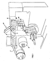
- fig. 1 is an overall perspective view of a cutting and rewinding machine according to the invention, provided for the division of a feeding tape into three smaller tapes;
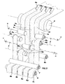
- fig. 2 is a perspective, diagrammatic, enlarged view of the assembly of the sole group of transmission cylinders only, which carries the already divided tapes towards the rewinding cylinders, in the case of an embodiment with a wide feeding tape divided into five narrower tapes.
- a very wide tape 1 is fed by a bobbin 2 through at least a first transmission cylinder 3, towards a cutting and division device 4, and to a second transmission cylinder 5.
- the cutting device comprises two cutting blades only, for division of tape 1 into three smaller tapes 1a, 1b, and 1c only.
- Fig. 2 shows the case, of more general interest, of the division of the feeding tape into five smaller tapes.
- the cutting device 4 consists of four cutting blades 4a, 4b, 4c, 4d, which are capable of performing four mutually parallel cuts which are also parallel to the tape flow direction, i.e. to the longitudinal axis of the machine, which divide the fed tape into five narrower tapes: for example, if starting tape 1 is 250 mm wide, it is divided into five tapes 1a, 1b, 1c, 1d and 1e, each 50 mm wide.
- a plurality of transmission cylinders Rx is provided with the function of deviating and separating tapes 1x, the arrangement of which is better described in the following; downstream of these cylinders Rx a single rewinding mandrel 6 is provided, as already said, preceded by a transmission and equalisation cylinder 7.
- a first main feature of the invention it is provided to perform fan-spreading of the separated tapes 1x in respect of the exit from cutting device 4, or better, of the exit from the first transmission cylinder 5 which is common to all tapes.
- first deviation cylinders Ra, Rb, Rc, Rd and Re one for each of said smaller tapes 1a, 1b, 1c, 1d and 1e deviating along fan paths.
- Transmission cylinders 3, 5, 7 and mandrel 6 are all arranged with their axes perfectly parallel to a transversal axis X-X of the machine, i.e. the axis of bobbin 2 feeding tape 1, which is perpendicular to the longitudinal axis Y-Y of the machine, i.e. to the flow direction of all tapes (fig.
- deviation cylinders Rx are mounted rotatable on axes at different angles to transversal axis x-x of the machine.
- said deviation cylinders are angled symmetrically to the longitudinal, central axis Y-Y of the machine.
- Downstream of deviation cylinders Rx means are secondly provided to bring separated tapes 1x back to parallel, mutually spaced paths.
- These means consist of transmission and realignment cylinders R'a, R'b, R'd and R'e, also one for each of said smaller tapes 1x; these cylinders R'x have axes parallel to the axes of deviation cylinders Rx and are offset on a plane by distance D'- and more precisely on a plane substantially perpendicular to the fan-forming plane - with respect to cylinders Ra, Rb, Rd and Re. If such fan-forming plane is substantially vertical - as in the case shown in fig. 2 for the plane lying between cylinder 5 and cylinders Ra, Rb, Rd and Re - then cylinders R'a, R'b, R'd and R'e will be offset in a horizontal plane.
- transmission cylinders Rx and R'x are arranged differently for each of tapes 1x; in particular, when feeding tape 1 is divided into an even number of tapes 1x, the following procedure is adopted:
- the two tapes 1b and 1d are guided to a vertical plane
- the central tape 1c is guided to a plane forming a small negative angle ⁇ with the vertical
- tapes 1a, 1e are guided to a plane forming a small positive angle + ⁇ with the vertical.
- two respective pairs of cylinders are provided, each formed by a deviation cylinder Rb and by a realignment cylinder R'b, and by cylinders Rd and R'd, respectively.
- the cylinders of each pair have mutually parallel axes, but such axes form, with transversal axis X-X of the machine (whereto the axis of mandrel 6, the axis of central cylinder Rc and the axes of all other cylinders 3,5,7 are parallel), a small angle, marked as ⁇ for cylinders Rb and R'b, and marked as - ⁇ (because they are of the same width, but of opposite sign) for the cylinder pair Rd and R'd;
- angle ⁇ for example equal to twice angle ⁇
Landscapes
- Replacement Of Web Rolls (AREA)
Abstract
Description
- The present invention relates to a method and to a machine for performing the cutting of a large adhesive tape and for the separation thereof in a plurality of smaller tapes, i.e. of the sizes used commercially, and for the rewinding of the latter.
- It is known that the rolls of adhesive tape on sale, for example the tapes employed in the packaging industry, and which are generally 50 mm wide, are manufactured from a large tape roll, for example a tape 450 mm wide. For such purpose, the latter is mounted on a respective rotatable supporting mandrel, then unwound and guided through a longitudinal cutting system, where it is separated into multiple parallel tapes of the sizes to be used, and these are then each rewound on their own spool.
- It is also known that these rewinding spools are normally mounted on two parallel rewinding mandrels, so that the tapes of the sizes to be used are rewound on spools which are alternately found on one mandrel and on the other: as a matter of fact, it is not possible to perform rewinding on a single mandrel, because should the tapes rewind on adjacent spools, they would end up sticking together due to the masses of adhesive found along their respective longitudinal edges.
- In the known semi-automatic machines, an arrangement is therefore provided wherein each of two distinct rewinding heads carries a pair of rewinding mandrels, one of which in a working position and the other in a waiting position. The rewinding spools are mounted on the two mandrels in the working position, which are driven in rotation to allow rewinding; while performing such rewinding, the operator prepares new spools on the two mandrels in the waiting position, which are non-driven. When the spools on the first mandrels are fully rewound, the heads perform a mandrel exchange, so that the second mandrel of each pair change from the waiting position into the working position, where a new rewinding process begins, and viceversa the second mandrel changes from the working position into the waiting position where the operator can unload the wound spools.
- In order to make these machines automatic, it is of course necessary to consider planning a double system for loading and unloading the spools on the mandrels, one for each of said two rewinding heads. This implies of course significant construction problems and high costs.
- In order to try to overcome these problems with a simpler machine, a rewinding system has been proposed by the Applicant itself comprising - between the cutting system and the rewinding means - a transmission cylinder in the shape of a double truncated cone having a major diameter in the middle and a minor diameter at the two ends; thereby, the starting tape is divided into two smaller-sized tapes which, by passing each on one of the cones of the transmission cylinder, are practically mutually drawn apart. Thus drawn apart, the tapes can then be rewound on respective spools, mounted on a same rotating mandrel, but at a short distance from each other. This arrangement, in addition to causing some rewinding problems - due to the fact that when the tapes to be rewound are drawn apart on a double-cone transmission cylinder, they are no longer perfectly planar with the rewinding spool - has a considerable limitation of use owing to the fact that it allows to operate exclusively when the starting tape is to be divided into two final tapes only.
- It is therefore an object of the present invention to propose a method and an automatic machine which solve the problem set forth above in a simple and inexpensive way, allowing to operate in all the cases in which a large starting tape is to be divided into a plurality at will of final tapes. This result is obtained by a method and a machine whose features are highlighted in
claims 1 and 5. - Further features and advantages of the method and of the machine according to the present invention will in any case be more evident from the following detailed description of some preferred embodiments, given purely as a non-limiting example and illustrated in the accompanying drawings, wherein:
- fig. 1 is an overall perspective view of a cutting and rewinding machine according to the invention, provided for the division of a feeding tape into three smaller tapes;
- fig. 2 is a perspective, diagrammatic, enlarged view of the assembly of the sole group of transmission cylinders only, which carries the already divided tapes towards the rewinding cylinders, in the case of an embodiment with a wide feeding tape divided into five narrower tapes.
- As can be seen from the view of fig. 1, a very wide tape 1 is fed by a
bobbin 2 through at least a first transmission cylinder 3, towards a cutting and division device 4, and to asecond transmission cylinder 5. - In the embodiment shown in fig. 1, the cutting device comprises two cutting blades only, for division of tape 1 into three
smaller tapes - Fig. 2 shows the case, of more general interest, of the division of the feeding tape into five smaller tapes. The cutting device 4 consists of four
cutting blades tapes - The following description concerns the structure and the mode of operation of the embodiments of fig. 2, but the same considerations are true - with the due simplifications which are well understandable to a person skilled in the field - for the embodiment of fig. 1.
- Downstream of cutting device 4 and of transmission cylinder 5 a plurality of transmission cylinders Rx is provided with the function of deviating and separating tapes 1x, the arrangement of which is better described in the following; downstream of these cylinders Rx a single rewinding
mandrel 6 is provided, as already said, preceded by a transmission and equalisation cylinder 7. - On
mandrel 6, five rewindingspools - In order to accomplish correct rewinding of separated tapes 1x on the spaced-apart spools, according to a first main feature of the invention, it is provided to perform fan-spreading of the separated tapes 1x in respect of the exit from cutting device 4, or better, of the exit from the
first transmission cylinder 5 which is common to all tapes. - However, simple fan-spreading is not sufficient, because the tapes would already become warped immediately after the exit from
transmission cylinder 5 and would arrive at an angle at the rewinding spools, consequently causing rewinding difficulties, i.e. spools which are unacceptable for the market. - For the purpose of obtaining instead a perfect, controlled spreading apart of cut tapes 1x, and according to a further important feature of the present invention, it is provided to guide tapes 1x, after fan-spreading thereof, so as to realign them to parallel, mutually distanced paths, before guiding them to rewind on their respective spools.
- For this purpose, between
cylinders 5 and 7 there are firstly provided first deviation cylinders Ra, Rb, Rc, Rd and Re, one for each of saidsmaller tapes Transmission cylinders 3, 5, 7 andmandrel 6 are all arranged with their axes perfectly parallel to a transversal axis X-X of the machine, i.e. the axis ofbobbin 2 feeding tape 1, which is perpendicular to the longitudinal axis Y-Y of the machine, i.e. to the flow direction of all tapes (fig. 1); on the contrary, deviation cylinders Rx are mounted rotatable on axes at different angles to transversal axis x-x of the machine. In a preferred embodiment, said deviation cylinders are angled symmetrically to the longitudinal, central axis Y-Y of the machine. - Downstream of deviation cylinders Rx, means are secondly provided to bring separated tapes 1x back to parallel, mutually spaced paths. These means consist of transmission and realignment cylinders R'a, R'b, R'd and R'e, also one for each of said smaller tapes 1x; these cylinders R'x have axes parallel to the axes of deviation cylinders Rx and are offset on a plane by distance D'- and more precisely on a plane substantially perpendicular to the fan-forming plane - with respect to cylinders Ra, Rb, Rd and Re. If such fan-forming plane is substantially vertical - as in the case shown in fig. 2 for the plane lying between
cylinder 5 and cylinders Ra, Rb, Rd and Re - then cylinders R'a, R'b, R'd and R'e will be offset in a horizontal plane. - More precisely, and as shown in fig. 2, transmission cylinders Rx and R'x are arranged differently for each of tapes 1x; in particular, when feeding tape 1 is divided into an even number of tapes 1x, the following procedure is adopted:
- at the exit from
cylinder 5 the twotapes tapes 1a, 1e are guided to a plane forming a small positive angle +γ with the vertical. These planes together form the so-called substantially vertical fan-forming plane - for guiding each of the first two
tapes mandrel 6, the axis of central cylinder Rc and the axes of allother cylinders 3,5,7 are parallel), a small angle, marked as α for cylinders Rb and R'b, and marked as -α (because they are of the same width, but of opposite sign) for the cylinder pair Rd and R'd; - for each of the further two
outermost tapes 1a and 1e, two respective pairs of deviation cylinder and realignment cylinder, respectively, are equally provided, marked as Ra, R'a and Re and R'e, respectively. The cylinders of each pair have again mutually parallel axes, but these axes form - with respect to said axis X-X - an angle marked as β and as ―β, respectively (because they are of the same width, but of opposite sign), which is larger (for example twice as large), in its absolute value, than angle α. - When the large tape is to be divided into an odd number of smaller tapes - precisely as shown in fig. 5 where five tapes 1x are shown - a single central cylinder Rc is provided, the axis thereof being parallel to axis X-X, whereon a central tape 1c of the assembly of five cut tapes is guided to run directly from
cylinder 5 to cylinder 7; in effect, the tape path must not be deviated, but must remain centred. If instead an even number of small tapes is to be obtained, the central guide on cylinder Rc is to be omitted. - According to the present invention, in order to achieve sufficient spreading apart of
tapes tapes 1a and 1e over the central tape (as well as even larger spreading apart for possible other tapes, should the starting tape be divided into more than four or five cut tapes) the following procedure can be followed: - on the basis of the only choice of angles α and β, and hence choosing angle β for example equal to twice angle α, and
- on the basis of the choice of angles α and β, but also according to the mutual distance d between the cylinders of each pair Ra-R'a, Rb-R'b, Rd-R'd or Re-R'e, respectively.
- It is intended, however, that the invention must not be considered limited to the particular arrangements illustrated above, which represent only exemplary embodiments thereof, but that different variants are possible, all within the reach of a person skilled in the field, without departing from the scope of protection of the invention, as defined by the following claims. In particular, it must be pointed out that the drawings show, and the text describes, cases exemplifying a large tape divided into three, or five, respectively, smaller adjacent tapes, by using two, or four, respectively, cutting blades. However, it is fully clear and understandable that a similar arrangement can be used for cutting a large tape into a different, odd or even, number of narrower tapes.
Claims (16)
- Method for cutting a large adhesive feeding tape into a plurality of smaller adhesive tapes, and for rewinding the latter on respective supporting spools, characterised in that, downstream of a cutting device, said smaller tapes are deviated fan-like along a substantially common first guiding plane, and successively realigned to parallel, mutually spaced-apart paths along second guiding planes forming an angle with said first guiding plane, before being rewound on said aligned spools.
- Method as in claim 1), wherein said smaller tapes, before being deviated fan-like, are guided to mutually adjacent, parallel alignments towards a transmission cylinder which is located immediately after the cutting device.
- Method as in claim 1) or 2), wherein said smaller tapes, after having been brought back to parallel paths, are rewound on coaxially mounted spools, side by side but slightly spaced apart, on a single supporting and rewinding mandrel.
- Method as in claim 1, wherein said second guiding and realignment planes are substantially perpendicular to said first guiding plane of the fan tapes.
- Machine for the cutting of a large adhesive feeding tape, into a plurality of smaller adhesive tapes, and for the rewinding of the latter on respective supporting spools, of the type comprising means for cutting and separating the feeding tape into said smaller tapes and means for rewinding said smaller tapes on respective supporting spools, characterised in that, in the path between said cutting means and said rewinding spools, it comprises means (Ra, Rb, Rc, Rd, Re) for deviating said smaller tapes (1a, 1b, 1c, 1d, 1e) to fan paths.
- Machine as in claim 5), characterised in that said means for deviation to fan paths along a substantially common first plane comprise first deviation cylinders (Ra, Rb, Rd, Re), one for each of said smaller tapes, rotating about axes lying at different angles (α, β, ―α, ―β) to a transversal axis (X-X) of the machine.
- Machine as in claim 6), characterised in that the axes of said first deviation cylinders (Ra, Rb, Rd, Re) are angled symmetrically on one side and on the opposite side, respectively, of a longitudinal, central axis (Y-Y) of the machine.
- Machine as in claim 5), 6) or 7), characterised in that, when said smaller tapes are in an odd number, said means for deviation to fan paths further comprise a central deviation cylinder (Rc) with an axis parallel to the transversal axis (X-X) of the machine.
- Machine as in claim 5) or 8), characterised in that, downstream of said fan deviation means (Ra, Rb, Rc, Rd, Re), it further comprises means (R' a, R'b, R'c, R'd, R'c) to realign said smaller tapes (1a, 1b, 1c, 1d, 1e) to parallel, mutually spaced apart paths.
- Machine as in claim 9), characterised in that said means to realign said smaller tapes to parallel paths consist of realignment cylinders (R'a, R'b, R'd and R'e), which are parallel but offset, with respect to deviation cylinders (Ra, Rb, Rd and Re).
- Machine as in claim 10), characterised in that said realignment cylinders (R'a, R'b, R'd and R'e) are offset, with respect to deviation cylinders (Ra, Rb, Rd and Re), on planes which are substantially perpendicular to said fan-forming plane.
- Machine as in claim 10), characterised in that said deviation cylinders (Ra, Rb, Rc, Rd and Re) are arranged downstream of said first transmission cylinder (5) in such a position as to guide said smaller tapes (1x) to a substantially vertical fan-forming plane, that said realignment cylinders (R'a, R'b, R'd and R'e) are arranged downstream of said deviation cylinders in such a position as to guide said tapes (1x) to a substantially horizontal plane and in that, downstream of said realignment cylinders an equalisation cylinder (7) is located, common to all tapes (1x) and in such a position as to guide said tapes (1x) to a substantially vertical plane.
- Machine as in claim 5) or 9), characterised in that it comprises a single rewinding mandrel, with an axis parallel to the transversal axis (X-X) of the machine, supporting spools (6a, 6b, 6c, 6d, 6e) of said smaller tapes (1x) being provisionally mounted on said mandrel side by side but slightly spaced apart from each other.
- Machine as in claim 12) and 13), characterised in that said rewinding mandrel is parallel to said equalisation cylinder (7) and is spaced apart therefrom on a horizontal plane.
- Machine as in claim 13) or 14), characterised in that it comprises means for the automatic loading and unloading of said supporting spools on said single rewinding mandrel.
- Machine as in claim 15), wherein said means for the automatic loading and unloading of supporting spools are associated with a waiting station, for said single rewinding mandrel, distinct from the rewinding station thereof.
Applications Claiming Priority (1)
| Application Number | Priority Date | Filing Date | Title |
|---|---|---|---|
| ITMI20041669 ITMI20041669A1 (en) | 2004-08-26 | 2004-08-26 | METHOD AND MACHINE FOR CUTTING A SELF-ADHESIVE TAPE IN A MULTIPLE OF THIN TAPES AND FOR THEIR REWINDING. |
Publications (2)
| Publication Number | Publication Date |
|---|---|
| EP1637488A2 true EP1637488A2 (en) | 2006-03-22 |
| EP1637488A3 EP1637488A3 (en) | 2007-03-21 |
Family
ID=35482188
Family Applications (1)
| Application Number | Title | Priority Date | Filing Date |
|---|---|---|---|
| EP05107780A Withdrawn EP1637488A3 (en) | 2004-08-26 | 2005-08-24 | Method and machine for cutting an adhesive tape in a plurality of narrow tapes and for the rewinding thereof |
Country Status (2)
| Country | Link |
|---|---|
| EP (1) | EP1637488A3 (en) |
| IT (1) | ITMI20041669A1 (en) |
Cited By (9)
| Publication number | Priority date | Publication date | Assignee | Title |
|---|---|---|---|---|
| WO2010066916A1 (en) * | 2008-12-10 | 2010-06-17 | Mimcord, S.A. | Method and system for obtaining paper strips and/or tapes |
| EP2305586A2 (en) | 2009-10-05 | 2011-04-06 | Krones AG | Device for guiding a variable number of sub-strips of a continuous film and method for changing an initial number to a second number of guided sub-strips |
| CN103121603A (en) * | 2013-01-24 | 2013-05-29 | 河南科技大学 | Flexible material rewinding slitting system and rewinding slitting mechanism thereof |
| CN103380073A (en) * | 2011-02-14 | 2013-10-30 | 日东电工株式会社 | Roll manufacturing method and roll |
| DE102012009648A1 (en) * | 2012-05-14 | 2013-11-14 | Weber Maschinenbau Gmbh Breidenbach | spreading |
| WO2013160814A3 (en) * | 2012-04-26 | 2014-03-27 | Pirelli Tyre S.P.A. | Process and production line for controlled collection of continuous strip-like elements for building tyres |
| CN106829608A (en) * | 2017-01-03 | 2017-06-13 | 东莞理工学院 | A fully automatic slitting and winding machine for adhesive tape |
| CN109436879A (en) * | 2018-12-10 | 2019-03-08 | 广州市易鸿智能装备有限公司 | Banding machine |
| CN114933198A (en) * | 2022-06-09 | 2022-08-23 | 珠海趣印科技有限公司 | Adhesive tape rewinding mechanism |
Family Cites Families (5)
| Publication number | Priority date | Publication date | Assignee | Title |
|---|---|---|---|---|
| US3719316A (en) * | 1971-04-22 | 1973-03-06 | Beloit Corp | Web spreader element |
| US4300714A (en) * | 1980-01-17 | 1981-11-17 | Beloit Corporation | Method and apparatus for silencing of webs |
| US4811880A (en) * | 1987-11-17 | 1989-03-14 | M-A-N Ashton Inc. | Continuous web handling apparatus and method of separating web sections |
| US5842663A (en) * | 1997-02-06 | 1998-12-01 | Kt Industries Inc. | Winding of tape into pads |
| DE10234674B4 (en) * | 2002-07-30 | 2010-04-29 | Wifag Maschinenfabrik Ag | Bahnspreizvorrichtung |
-
2004
- 2004-08-26 IT ITMI20041669 patent/ITMI20041669A1/en unknown
-
2005
- 2005-08-24 EP EP05107780A patent/EP1637488A3/en not_active Withdrawn
Cited By (14)
| Publication number | Priority date | Publication date | Assignee | Title |
|---|---|---|---|---|
| WO2010066916A1 (en) * | 2008-12-10 | 2010-06-17 | Mimcord, S.A. | Method and system for obtaining paper strips and/or tapes |
| CN102030214B (en) * | 2009-10-05 | 2014-05-21 | 克罗内斯股份公司 | Device for guiding a variable number of sub-strips of a continuous film and method for changing number of guided sub-strips |
| EP2305586A2 (en) | 2009-10-05 | 2011-04-06 | Krones AG | Device for guiding a variable number of sub-strips of a continuous film and method for changing an initial number to a second number of guided sub-strips |
| DE102009044473A1 (en) | 2009-10-05 | 2011-04-07 | Krones Ag | Device for guiding a variable number of partial webs of a continuous film and method for changing a first number to a second number of guided partial webs |
| CN102030214A (en) * | 2009-10-05 | 2011-04-27 | 克罗内斯股份公司 | Device for guiding a variable number of sub-strips of a continuous film and method for changing number of guided sub-strips |
| CN103380073B (en) * | 2011-02-14 | 2015-11-25 | 日东电工株式会社 | Roll manufacturing method and roll |
| CN103380073A (en) * | 2011-02-14 | 2013-10-30 | 日东电工株式会社 | Roll manufacturing method and roll |
| WO2013160814A3 (en) * | 2012-04-26 | 2014-03-27 | Pirelli Tyre S.P.A. | Process and production line for controlled collection of continuous strip-like elements for building tyres |
| EP3453642A1 (en) * | 2012-04-26 | 2019-03-13 | Pirelli Tyre S.p.A. | Process and production line for controlled collection of continuous strip-like elements for building tyres |
| DE102012009648A1 (en) * | 2012-05-14 | 2013-11-14 | Weber Maschinenbau Gmbh Breidenbach | spreading |
| CN103121603A (en) * | 2013-01-24 | 2013-05-29 | 河南科技大学 | Flexible material rewinding slitting system and rewinding slitting mechanism thereof |
| CN106829608A (en) * | 2017-01-03 | 2017-06-13 | 东莞理工学院 | A fully automatic slitting and winding machine for adhesive tape |
| CN109436879A (en) * | 2018-12-10 | 2019-03-08 | 广州市易鸿智能装备有限公司 | Banding machine |
| CN114933198A (en) * | 2022-06-09 | 2022-08-23 | 珠海趣印科技有限公司 | Adhesive tape rewinding mechanism |
Also Published As
| Publication number | Publication date |
|---|---|
| EP1637488A3 (en) | 2007-03-21 |
| ITMI20041669A1 (en) | 2004-11-26 |
Similar Documents
| Publication | Publication Date | Title |
|---|---|---|
| US3741079A (en) | Web splicing methods | |
| SE446951B (en) | DEVICE FOR SLITING A LONG-TERM PRIMER BAND | |
| JPH05246603A (en) | Device for cross cutting and/or perforating of web | |
| AU753644B2 (en) | Method for order changing in corrugating machines | |
| CN104684827B (en) | Drag element for dragging web material | |
| ITBO930112A1 (en) | METHOD AND DEVICE FOR THE AUTOMATIC JOINTING OF TAPES PERFORMED BY REELS. | |
| CA1334023C (en) | Core loading device for web-slitting machine | |
| US9701507B2 (en) | Method and device for the production of a number of coiled foil rolls | |
| US4606534A (en) | Combined separating, bursting and sorting apparatus for a continuous web of multi-forms | |
| JPH1067464A (en) | Folding device | |
| US11772318B2 (en) | Fiber product folding apparatus | |
| EP0359174B1 (en) | Web winding apparatus | |
| US8616101B2 (en) | Process and device for manufacturing a product from strip tape, especially for manufacturing a medicinal and/or active substance-containing product as well as fillable containers or sealed-margin bags | |
| US3940081A (en) | Flat core for web windings | |
| US5184788A (en) | Apparatus for guiding and more particularly coiling webs of material | |
| CA1310346C (en) | Continuous web handling apparatus and method of separating web sections | |
| EP0208244B1 (en) | Apparatus for continuously trimming a feed of overlapping printed products | |
| JP2003048020A (en) | Narrow strip coiling device | |
| JP7493760B2 (en) | Cushioning material supply device | |
| US20050263936A1 (en) | Device for producing film webs from a film tube by cutting open the squeezed air buble | |
| CN223813156U (en) | Narrow-band conveyor and slitting/rewinding machine | |
| EP0931742B1 (en) | Winding machine to wind the single strips of a slitted web | |
| JP2002205851A (en) | Slitter device | |
| CN215241290U (en) | Die cutting equipment | |
| JPH05253890A (en) | Cutting method for web |
Legal Events
| Date | Code | Title | Description |
|---|---|---|---|
| PUAI | Public reference made under article 153(3) epc to a published international application that has entered the european phase |
Free format text: ORIGINAL CODE: 0009012 |
|
| AK | Designated contracting states |
Kind code of ref document: A2 Designated state(s): AT BE BG CH CY CZ DE DK EE ES FI FR GB GR HU IE IS IT LI LT LU LV MC NL PL PT RO SE SI SK TR |
|
| AX | Request for extension of the european patent |
Extension state: AL BA HR MK YU |
|
| PUAL | Search report despatched |
Free format text: ORIGINAL CODE: 0009013 |
|
| AK | Designated contracting states |
Kind code of ref document: A3 Designated state(s): AT BE BG CH CY CZ DE DK EE ES FI FR GB GR HU IE IS IT LI LT LU LV MC NL PL PT RO SE SI SK TR |
|
| AX | Request for extension of the european patent |
Extension state: AL BA HR MK YU |
|
| RIC1 | Information provided on ipc code assigned before grant |
Ipc: B65H 23/035 20060101ALI20070213BHEP Ipc: B65H 23/038 20060101ALI20070213BHEP Ipc: B65H 35/02 20060101AFI20070213BHEP |
|
| AKX | Designation fees paid | ||
| STAA | Information on the status of an ep patent application or granted ep patent |
Free format text: STATUS: THE APPLICATION IS DEEMED TO BE WITHDRAWN |
|
| 18D | Application deemed to be withdrawn |
Effective date: 20070922 |
|
| REG | Reference to a national code |
Ref country code: DE Ref legal event code: 8566 |