EP1637484A2 - Planographic printing plate feeding apparatus - Google Patents
Planographic printing plate feeding apparatus Download PDFInfo
- Publication number
- EP1637484A2 EP1637484A2 EP05255689A EP05255689A EP1637484A2 EP 1637484 A2 EP1637484 A2 EP 1637484A2 EP 05255689 A EP05255689 A EP 05255689A EP 05255689 A EP05255689 A EP 05255689A EP 1637484 A2 EP1637484 A2 EP 1637484A2
- Authority
- EP
- European Patent Office
- Prior art keywords
- planographic printing
- printing plate
- leading edge
- uppermost
- interleaf paper
- Prior art date
- Legal status (The legal status is an assumption and is not a legal conclusion. Google has not performed a legal analysis and makes no representation as to the accuracy of the status listed.)
- Withdrawn
Links
- 238000003825 pressing Methods 0.000 claims description 5
- 239000011347 resin Substances 0.000 claims description 3
- 229920005989 resin Polymers 0.000 claims description 3
- 230000014759 maintenance of location Effects 0.000 claims description 2
- 230000000979 retarding effect Effects 0.000 description 13
- 238000011144 upstream manufacturing Methods 0.000 description 6
- 238000000926 separation method Methods 0.000 description 5
- 238000007599 discharging Methods 0.000 description 4
- 230000007246 mechanism Effects 0.000 description 3
- 235000004443 Ricinus communis Nutrition 0.000 description 2
- 240000000528 Ricinus communis Species 0.000 description 2
- 238000005452 bending Methods 0.000 description 2
- 238000010586 diagram Methods 0.000 description 2
- 230000000694 effects Effects 0.000 description 2
- 238000000034 method Methods 0.000 description 2
- 238000009825 accumulation Methods 0.000 description 1
- XAGFODPZIPBFFR-UHFFFAOYSA-N aluminium Chemical compound [Al] XAGFODPZIPBFFR-UHFFFAOYSA-N 0.000 description 1
- 229910052782 aluminium Inorganic materials 0.000 description 1
- 239000003795 chemical substances by application Substances 0.000 description 1
- 238000003780 insertion Methods 0.000 description 1
- 230000037431 insertion Effects 0.000 description 1
- 238000004519 manufacturing process Methods 0.000 description 1
- 239000000463 material Substances 0.000 description 1
- 230000001681 protective effect Effects 0.000 description 1
Images




Classifications
-
- B—PERFORMING OPERATIONS; TRANSPORTING
- B65—CONVEYING; PACKING; STORING; HANDLING THIN OR FILAMENTARY MATERIAL
- B65H—HANDLING THIN OR FILAMENTARY MATERIAL, e.g. SHEETS, WEBS, CABLES
- B65H3/00—Separating articles from piles
- B65H3/46—Supplementary devices or measures to assist separation or prevent double feed
- B65H3/56—Elements, e.g. scrapers, fingers, needles, brushes, acting on separated article or on edge of the pile
-
- B—PERFORMING OPERATIONS; TRANSPORTING
- B41—PRINTING; LINING MACHINES; TYPEWRITERS; STAMPS
- B41F—PRINTING MACHINES OR PRESSES
- B41F1/00—Platen presses, i.e. presses in which printing is effected by at least one essentially-flat pressure-applying member co-operating with a flat type-bed
-
- B—PERFORMING OPERATIONS; TRANSPORTING
- B41—PRINTING; LINING MACHINES; TYPEWRITERS; STAMPS
- B41F—PRINTING MACHINES OR PRESSES
- B41F1/00—Platen presses, i.e. presses in which printing is effected by at least one essentially-flat pressure-applying member co-operating with a flat type-bed
- B41F1/18—Platen presses, i.e. presses in which printing is effected by at least one essentially-flat pressure-applying member co-operating with a flat type-bed for lithography
-
- B—PERFORMING OPERATIONS; TRANSPORTING
- B41—PRINTING; LINING MACHINES; TYPEWRITERS; STAMPS
- B41F—PRINTING MACHINES OR PRESSES
- B41F1/00—Platen presses, i.e. presses in which printing is effected by at least one essentially-flat pressure-applying member co-operating with a flat type-bed
- B41F1/26—Details
-
- B—PERFORMING OPERATIONS; TRANSPORTING
- B65—CONVEYING; PACKING; STORING; HANDLING THIN OR FILAMENTARY MATERIAL
- B65H—HANDLING THIN OR FILAMENTARY MATERIAL, e.g. SHEETS, WEBS, CABLES
- B65H1/00—Supports or magazines for piles from which articles are to be separated
-
- B—PERFORMING OPERATIONS; TRANSPORTING
- B65—CONVEYING; PACKING; STORING; HANDLING THIN OR FILAMENTARY MATERIAL
- B65H—HANDLING THIN OR FILAMENTARY MATERIAL, e.g. SHEETS, WEBS, CABLES
- B65H3/00—Separating articles from piles
- B65H3/02—Separating articles from piles using friction forces between articles and separator
- B65H3/06—Rollers or like rotary separators
- B65H3/0653—Rollers or like rotary separators for separating substantially vertically stacked articles
-
- B—PERFORMING OPERATIONS; TRANSPORTING
- B65—CONVEYING; PACKING; STORING; HANDLING THIN OR FILAMENTARY MATERIAL
- B65H—HANDLING THIN OR FILAMENTARY MATERIAL, e.g. SHEETS, WEBS, CABLES
- B65H3/00—Separating articles from piles
- B65H3/02—Separating articles from piles using friction forces between articles and separator
- B65H3/06—Rollers or like rotary separators
- B65H3/0669—Driving devices therefor
-
- B—PERFORMING OPERATIONS; TRANSPORTING
- B65—CONVEYING; PACKING; STORING; HANDLING THIN OR FILAMENTARY MATERIAL
- B65H—HANDLING THIN OR FILAMENTARY MATERIAL, e.g. SHEETS, WEBS, CABLES
- B65H3/00—Separating articles from piles
- B65H3/32—Separating articles from piles by elements, e.g. fingers, plates, rollers, inserted or traversed between articles to be separated and remainder of the pile
-
- B—PERFORMING OPERATIONS; TRANSPORTING
- B65—CONVEYING; PACKING; STORING; HANDLING THIN OR FILAMENTARY MATERIAL
- B65H—HANDLING THIN OR FILAMENTARY MATERIAL, e.g. SHEETS, WEBS, CABLES
- B65H2405/00—Parts for holding the handled material
- B65H2405/10—Cassettes, holders, bins, decks, trays, supports or magazines for sheets stacked substantially horizontally
- B65H2405/11—Parts and details thereof
- B65H2405/113—Front, i.e. portion adjacent to the feeding / delivering side
- B65H2405/1134—Front, i.e. portion adjacent to the feeding / delivering side movable, e.g. pivotable
-
- B—PERFORMING OPERATIONS; TRANSPORTING
- B65—CONVEYING; PACKING; STORING; HANDLING THIN OR FILAMENTARY MATERIAL
- B65H—HANDLING THIN OR FILAMENTARY MATERIAL, e.g. SHEETS, WEBS, CABLES
- B65H2701/00—Handled material; Storage means
- B65H2701/10—Handled articles or webs
- B65H2701/18—Form of handled article or web
- B65H2701/182—Piled package
- B65H2701/1826—Arrangement of sheets
- B65H2701/18264—Pile of alternate articles of different properties, e.g. pile of working sheets with intermediate sheet between each working sheet
-
- B—PERFORMING OPERATIONS; TRANSPORTING
- B65—CONVEYING; PACKING; STORING; HANDLING THIN OR FILAMENTARY MATERIAL
- B65H—HANDLING THIN OR FILAMENTARY MATERIAL, e.g. SHEETS, WEBS, CABLES
- B65H2701/00—Handled material; Storage means
- B65H2701/10—Handled articles or webs
- B65H2701/19—Specific article or web
- B65H2701/1928—Printing plate
Definitions
- the present invention relates to a planographic printing plate feeding apparatus, and particularly to a planographic printing plate feeding apparatus in which sets of planographic printing plate and an interleaf paper are fed out one set at a time from a stack of alternately stacked planographic printing plates and interleaf papers.
- planographic printing plates each with a protective interleaf paper closely adhering to an image recording surface thereof, are stacked in the direction of the thickness thereof, thereby forming a stack of planographic printing plates.
- planographic printing plates are taken out from the stack one by one, and fed to the exposure apparatus.
- JP-A Japanese Patent Application Laid-Open
- JP-A No. 60-202028 discloses the technique in which an interleaf paper is fed out by a roller, and a planographic printing plate is fed out by a vacuum pad.
- planographic printing plates and interleaf papers are taken out separately one by one, the next planographic printing plate can be taken out only after the interleaf paper has been removed, hence feeding of the plates takes a significant amount of time.
- separate discharging mechanisms are required for offtaking the planographic printing plates and interleaf papers, and so an increase in the number of parts, size, and cost of the apparatus is likely to result.
- a structure could be considered in which a plate (separation plate) is provided, so as to restrict movement of all planographic printing plates other than the uppermost.
- the separation plate acts by making contact with all the planographic printing plates, other than the uppermost one, on the downstream side of the stack, with respect to the direction in which the planographic printing plate is conveyed.
- a high degree of accuracy is required for the mounting of the separation plate.
- a planographic printing plate feeding apparatus comprises: a conveyor that conveys an uppermost planographic printing plate and an interleaf paper adhering thereto, by rotating while pressing a stack in which planographic printing plates and interleaf papers are alternately stacked; and a guide member provided at the downstream side of the stack, with respect to the direction in which the planographic printing plate is conveyed.
- the guide member is provided so as to abut the leading edge of the uppermost planographic printing plate being conveyed, so as to bend the planographic printing plate, and allow the uppermost planographic printing plate and interleaf paper to pass over the guide member, while the guide member is being inclined due to being pressed by the planographic printing plate.
- the conveyor conveys a planographic printing plate and an interleaf paper by rotating while pressing the stack.
- the conveyor conveys a planographic printing plate and an interleaf paper by rotating while pressing the stack.
- the conveyor conveys a planographic printing plate and an interleaf paper by rotating while pressing the stack.
- a structure could be considered providing a stopping member at the downstream side, with respect to the direction in which the planographic printing plate is conveyed, of the planographic printing plate stack.
- the stopping member could abut all layers in the stack other than the uppermost planographic printing plate and an interleaf paper adhering thereto. This would stop the conveying of planographic printing plates and interleaf papers adhering thereto, stacked below the uppermost planographic printing plate and the interleaf paper adhering thereto.
- the stopping member is disposed so as not to abut the uppermost printing plate nor interleaf paper to be conveyed, and yet to abut against the underlying planographic printing plates, a high degree of accuracy is required for mounting. This makes production of the stopping member difficult.
- planographic printing plate feeding apparatus of the present invention is provided with guide members that also abut the uppermost planographic printing plate. Since the guide members may be allowed to abut the uppermost planographic printing plate, no high degree of accuracy is required for mounting.
- the guide members permits the passing of the uppermost planographic printing plate and interleaf paper adhering thereto, while the guide is being inclined due to being pressed by the uppermost planographic printing plate.
- the uppermost planographic printing plate and the interleaf paper adhering thereto are conveyed to the downstream side of the guide members, with respect to the conveying direction.
- the underlying planographic printing plate and interleaf paper adhering thereto are separated from the uppermost planographic printing plate and interleaf paper adhering thereto.
- This underlying plate and interleaf paper are hence left at the upstream side of the guide members with respect to the conveying direction and the plate is left in a state in which it abuts the guide members.
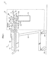
- Fig. 1 is a side view showing a planographic printing plate feeding apparatus according to an embodiment of the present invention.
- Fig. 2 is a perspective view showing a mounting section and a discharging section of the planographic printing plate feeding apparatus according to the embodiment of the present invention.
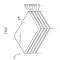
- Fig. 3 is a perspective view showing a stack of plates to be placed in the planographic printing plate feeding apparatus according to the embodiment of the present invention.
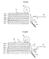
- Fig. 4A is a schematic side view showing a leading edge guide and a stack of plates in a state in which a pick-up roller is brought into contact with a planographic printing plate prior to conveying.
- Fig. 4B is a schematic side view showing a state in which two sets of planographic printing plates and interleaf papers are made to abut the leading edge guide after conveying has been started.
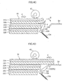
- Fig. 4C is a schematic side view showing a state in which the leading edge guide is being rotated, and the uppermost planographic printing plate and interleaf paper adhering thereto are being curved.
- Fig. 4D is a schematic side view showing a state in which the uppermost planographic printing plate and interleaf paper adhering thereto are passing over the leading edge guide.
- Fig. 4E is a schematic side view showing a state in which the leading edge guide returns towards the stack of plates, and the second uppermost planographic printing plate and interleaf paper adhering thereto are also returned towards the stack of plates.
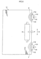
- Fig. 5 is a diagram showing, when seen from the top, the relationship corresponding to Fig. 4A between the leading edge guides and a stacked set of planographic printing plate and interleaf paper to be fed into the planographic printing plate feeding apparatus.
- Fig. 6 is a diagram showing, when seen from the top, the relationship corresponding to Fig. 4B between the leading edge guides and a stacked set of planographic printing plate and interleaf paper to be fed into the planographic printing plate feeding apparatus.
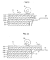
- Fig. 7A is a schematic side view showing the leading edge guide and the stack of plates in a state in which a pick-up roller is brought into contact with a planographic printing plate prior to conveying of the planographic printing plate in a planographic printing plate feeding apparatus according to another embodiment of the present invention.
- Fig. 7B is a schematic side view showing a state in which two sets of planographic printing plates and interleaf papers are made to abut the leading edge guide after starting conveying in the planographic printing plate feeding apparatus according to another embodiment of the present invention.
- Fig. 7C is a schematic side view showing a state in which the leading edge guide is being flexed and the uppermost planographic printing plate and interleaf paper adhering thereto are being bent in the planographic printing plate feeding apparatus according to another embodiment of the present invention.
- Fig. 7D is a schematic side view showing a state in which the uppermost planographic printing plate and interleaf paper adhering thereto are passing over the leading edge guide in the planographic printing plate feeding apparatus according to another embodiment of the present invention.
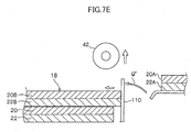
- Fig. 7E is a schematic side view showing a state in which the leading edge guide is being returned towards the stack of plates and the underlying planographic printing plate and interleaf paper adhering thereto are also being returned towards the stack of plates.
- Fig. 1 shows an overall structure of a planographic printing plate feeding apparatus 12 according to the present invention. Further, Fig. 2 shows a mounting section 14 and a discharging section 16 of the planographic printing plate feeding apparatus 12, with a stack of plates 18 being mounted on the mounting section 14.
- the planographic printing plate 20 is formed by applying a photosensitive agent onto one surface of a supporting base that is formed from aluminum or the like, to form a photosensitive surface 20E.
- Interleaf papers 22 that protect the photosensitive surfaces 20E, and the planographic printing plates 20 are stacked alternately to form the stack of plates 18.
- Fig. 3 shows a state in which the planographic printing plates 20 are stacked such that the photosensitive surfaces 20E face upwards, and the interleaf paper 22 that protects the photosensitive surface 20E of the uppermost planographic printing plate 20 is already removed.
- the planographic printing plate feeding apparatus 12 is provided with a stand section 26, and the mounting section 14 and the discharging section 16 are disposed on the stand portion 26.
- the stand section 26 is fitted with castors 28, and the castors 28 enable the entire planographic printing plate feeding apparatus 12 to move. This enables the apparatus 12 to be inserted or withdrawn from, for example, a planographic printing plate insertion portion of an exposure apparatus.
- the mounting section 14 has a flat rectangular mounting tray 30. Disposed in the mounting tray 30 are two side edge guide plates 32 and one trailing edge guide plate 34.
- the side edge guide plates 32 slide by a sliding mechanism (not shown) in the directions indicated by a double-headed arrow W, and are aligned with the side surfaces of the stack of plates 18 (formed from a plurality of stacked sets 24), according to the size of the planographic printing plates 20.
- the trailing edge guide plate 34 slides by a sliding mechanism (not shown) in the direction indicated by arrow F (and in a direction opposite thereto), and is aligned with the trailing edge of the stack of plates 18.
- a plurality of covers 36 are provided in the mounting portion 14 so as to cover the area around the mounted stack of plates 18.
- the cover 36A covers the end portion of the stack 18 at the downstream side, with respect to the direction in which the planographic printing plate is conveyed; and, when inserted in an exposure apparatus or the like is pressed upward by a pressing member (not shown), rotates around a hinge 38, and flies up. This state is shown in Fig. 1.
- a holder 40 is placed to span over the mounting section 14 in the widthwise direction of the stack of plates 18.
- a pick-up roller 42 is mounted rotatably in the holder 40 so as to be located above the stack of plates 18 mounted on the mounting section 14.
- the driving force of the driving motor 44 acts on the pick-up roller 42 via an endless belt 46, so that the pick-up roller 42 rotates in the direction of conveying the planographic printing plate 20 (and the interleaf paper 22).
- This direction will be hereinafter referred to as "forward rotation” and indicated by arrow J.
- the direction in which the planographic printing plate 20 is discharged is indicated by arrow F (and will be hereinafter referred to as “conveying direction F").
- "Widthwise” as used above is the direction orthogonal thereto, that is the widthwise direction parallel to the leading edge of the planographic printing plates 20, and is indicated by arrow W (which will be hereinafter referred to as "widthwise direction W").
- the holder 40 is made rotatable around supporting shafts 48 which are provided at both ends thereof in the widthwise direction W and on the downstream edge of the holder 40 with respect to the conveying direction F. Due to a rotational driving force from a driving unit 50 provided at the side of the holder 40, the pick-up roller 42 is rotated between: a conveying position in which it comes into contact with the stack of plates 18, with a predetermined load acting thereon; and a separated position in which the pick-up roller 42 is moved away from the stack of plates 18.
- the bottom of the mounting tray 30 is formed as a mounting plate 52 that swings due to a hinge (not shown) provided at the upstream side of the mounting plate 52 with respect to the conveying direction F.
- the mounting plate 52, on which the stack of plates 18 is mounted, is urged upwards by an urging member (not shown), ensuring that the uppermost planographic printing plate 20 reliably comes into contact with the pick-up roller 42.
- Two guide plates 54 and 56 are disposed sequentially at the downstream side of the mounting portion 14 at predetermined intervals in the conveying direction F.
- the planographic printing plate 20 is conveyed while being supported by the guide plates 54 and 56.
- leading edge guides 100 are provided, as guides, between the stack of plates 18 mounted on the mounting plate 52 and the guide plate 54. As shown in Fig. 5, the leading edge guides 100 are provided at two positions equidistant from the stack of plates 18. The leading edge guides 100 are provided outside, in the widthwise direction W, of a region N where the pick-up roller 42 and the uppermost planographic printing plate 20 contact each other (which uppermost planographic printing plate 20 will be hereinafter referred to as "planographic printing plate 20A").
- the planographic printing plate 20 In the contact area N, it is not easy to generate a bending moment, and so even if movement of the uppermost planographic printing plate 20 is prevented by the leading edge guides 100, the planographic printing plate 20 would not be easily bent.
- leading edge guides 100 are provided at a height so that they abut both the planographic printing plate 20A and the underlying planographic printing plate 20 (which will be hereinafter referred to as "planographic printing plate 20B") when the planographic printing plate 20A and the planographic printing plate 20B are conveyed by the pick-up roller 42 (see Fig. 4A).
- the leading edge guides 100 can be formed from, for example, POM-based resin or another material. Since the interleaf paper 22 is conveyed together with the uppermost planographic printing plate 20 while making contact with the leading edge guides 100, if the friction between the leading edge guides 100 and the interleaf paper 22 is large, a jam can result. When the leading edge guides 100 are formed from POM-based resin as described above, the interleaf paper 22 easily slides over the leading edge guides 100, thereby making it possible to prevent a jam of the interleaf papers 22.
- leading edge guides 100 The portion of the leading edge guides 100 is tapered, at the side closest to the guide plate 54 towards the top, so as to slope down away from the stack of plates 18. Due to the leading edge guides 100 having the aforementioned shape, it is possible to reduce the space required by the leading edge guide 100 for rotation in the conveying direction as described below.
- Guide shafts 102 are inserted through the lower portion of the leading edge guides 100 along the widthwise direction W.
- the leading edge guides 100 are rotatable around the guide shafts 102.
- one end of a helical tension spring 104 serving as urging means, is mounted at the lower end of the leading edge guides 100.
- the other end of the helical tension spring 104 is fixed at a stationary portion (not shown), and the helical tension spring 104 generates torque in the leading edge guides 100, with the guide shaft 102 serving as a fulcrum.
- the leading edge guides 100 are urged to the upstream side with respect to the conveying direction, that is, against the side of the stack of plates 18.
- leading edge guides 100 when in the state of not being pressed, are restrained from rotating by abutting stoppers 106, serving as position retention members, and the surfaces of the leading edge guides 100 facing the stack of plates 18 are held in reference position P1, that is parallel to the stack of plates 18 (see Fig. 4A).
- leading edge guides 100 When the leading edge guides 100 are pressed from the upstream side, with respect to the conveying direction, they are induced to incline by rotating around the guide shafts 102 in the direction indicated by arrow Q, and the helical tension springs 104 extend.
- the direction indicated by arrow Q has a component in the vertical direction towards the lower side of the stack of plates 18.
- the leading edge guides 100 are rotated in the direction indicated by arrow Q to a position at which the planographic printing plate 20A and the interleaf paper 22A can be moved to the downstream side of the leading edge guided 100, with respect to the conveying direction (which position will be hereinafter referred to as "retracted position P2"), see Fig. 4D.
- an interleaf paper separating device 58 is disposed between the guide plates 54 and 56.
- the interleaf paper separating device 58 has a conveying roller unit 60 and a retarding roller unit 62, which are sequentially disposed in the conveying direction F.
- Each of the roller units as shown in Fig. 2, is formed by a shaft 64, that is rotatable and spans along the widthwise direction W, with a plurality of rubber rollers 66 fixed onto each shaft 64 at predetermined intervals.
- the retarding roller unit 62 is moved by a driving unit 68, provided at one end thereof, between a position where it is in contact with the interleaf paper 22 in the state of being conveyed, and a position where it is moved away from the interleaf paper 22.
- a driving unit 68 provided at one end thereof, between a position where it is in contact with the interleaf paper 22 in the state of being conveyed, and a position where it is moved away from the interleaf paper 22.
- the rubber rollers 66 of the retarding roller unit 62 also come into contact with the rubber rollers 66 of the conveying roller unit 60 so that the interleaf paper 22 can be nipped between the rubber rollers 66 of the returned roller unit 62 and the rubber rollers 66 of the conveying roller unit 60.
- a nip roller 70 is provided spanning above the conveying roller unit 60 in the widthwise direction in a rotatable manner.
- the nip roller 70 comes into contact with the planographic printing plate 20, due to its own weight, in such a manner as to be capable of nipping the planographic printing plate 20 and the interleaf paper 22 between itself and the rubber rollers 66 of the conveying roller unit 60.
- Interleaf paper conveying roller units 72A and 72B are disposed below the conveying roller unit 60 and the retarding roller unit 62, respectively.
- the interleaf paper conveying roller units 72A and 72B are also each formed in the same manner as the conveying roller unit 60 and the retarding roller unit 62, with shafts 64 and rubber rollers 66.
- the interleaf paper 22 can hence be nipped between the rubber rollers 66 of the interleaf paper conveying roller units 72A and 72B, and with the rotation of the rubber rollers 66 of the interleaf paper conveying roller units 72A and 72B, the interleaf papers 22 are nipped therebetween and can be conveyed downward along conveying belts 74.
- an accumulating box 76 is Provided below the interleaf paper conveying roller units 72A and 72B, in which the interleaf papers 22 are accumulated.
- planographic printing plates 20 are fed into an exposure apparatus using the planographic printing plate feeding apparatus 12 with the structure described above, first, the stack of plates 18 is mounted in the mounting portion 14. At this time, the stack of plates 18 is aligned in such a manner that the trailing edge 18B of the stack 18 comes into contact with the trailing edge guide plate 34, and the side edges of the stack 18 come into contact with the side-edge guide plates 32.
- the cover 36A rotates upwards and a portion of the stack of plates 18 (in the vicinity of the front end thereof) is uncovered.
- the pick-up roller 42 is brought into contact with the stack of plates 18 (see Fig. 4A).
- planographic printing plate 20A and the interleaf paper 22A are conveyed in the conveying direction F.
- the planographic printing plate 20A and the planographic printing plate 20B are made to closely adhere to each other by a vacuum effect, or if air flows into the region between the planographic printing plate 20B and the underlying planographic printing plate 20C, then the underlying planographic printing plate 20B and the interleaf paper 22B are also conveyed in the conveying direction F together with the uppermost planographic printing plate 20A and the interleaf paper 22A, as shown in Fig. 4B.
- the planographic printing plate 20A and the interleaf paper 22A adhering thereto, and the planographic printing plate 20B and the interleaf paper 22B adhering thereto are made to abut against the leading edge guides 100 disposed at reference position P1.
- the leading edge guides 100 are pressed by the planographic printing plate 20A and the planographic printing plate 20B and rotate in the direction indicated by arrow Q (see Fig. 4C). At this time, the leading edge portions of the planographic printing plate 20A and the planographic printing plate 20B are bent due to a reaction force from the leading edge guides 100. Due to the difference of curvature between the planographic printing plate 20A and the planographic printing plate 20B, air E flows into a region between the planographic printing plate 20A and the planographic printing plate 20B, as also shown in Fig. 6.
- the planographic printing plate 20A (with interleaf paper 22A) and the planographic printing plate 20B (with interleaf paper 22B) are easily separated from each other.
- the leading edge guides 100 are provided outside, in the widthwise direction W, of the contact area N in which the pick-up roller 42 and the planographic printing plate 20A are in contact with each other. Therefore, as compared with a case in which the leading edge guides 100 are provided inside of the contact area N, the leading edge of the planographic printing plate 20A is more easily bent, and a greater inflow of air E can be achieved.
- leading edge guides 100 are further rotated in the direction indicated by arrow Q, by being pressed by the planographic printing plate 20A.
- Leading edge guides 100 are hence retracted to position P2, thereby allowing the planographic printing plate 20A and the interleaf paper 22A to move past the leading edge guides 100 (see Fig. 4D).
- the planographic printing plate 20A and the interleaf paper 22A are conveyed to the downstream side of the leading edge guides 100, with respect to the conveying direction F.
- planographic printing plate 20B and the interleaf paper 22B are separated from the planographic printing plate 20A and the interleaf paper 22A, and are left on the upstream side of the leading edge guide 100 with respect to the conveying direction F.
- the leading edge guides 100 are of a simple structure, not requiring accurate positioning, which enables reliable conveying of only the uppermost planographic printing plate 20A and the interleaf paper 22A adhering thereto.
- the interleaf paper 22 is separated from the planographic printing plate 20 in the interleaf paper separating device 58 in such a manner as described below.
- the conveying roller unit 60 and the retarding roller unit 62 are rotated and the retarding roller unit 62 is moved upwards. Due to the rubber rollers 66 of the retarding roller unit 62 making contact with the interleaf paper 22 while rotating in the reverse direction, a force from the conveying roller unit 60 (operating in the conveying direction), and a force from the retarding roller unit 62 (operating in the opposite direction) both act on the interleaf paper 22.
- the interleaf paper 22 is conveyed downwards, in a bent and folded condition, while being nipped by the rubber rollers 66 of the conveying roller unit 60 and the rubber rollers 66 of the retarding roller unit 62.
- the interleaf paper 22 is subsequently discharged into an accumulation box 76.
- the planographic printing plate 20 is further conveyed in the conveying direction F, and delivered to the exposure apparatus.
- leading edge guides 100 are made rotatable around the guide shafts 102, and urged by helical tension springs 104 to the upstream side with respect to the conveying direction.
- the leading edge guides are not limited to the same.
- leading edge guides 110 formed by elastic plates that are elastically deformable, requiring no helical tension spring 104 can be used, as shown in Figs. 7A to 7E. In this case, lower base end portions of the leading edge guides 110 of the elastic plate leading edge guides 110 are fixed and the upper end portions formed as free ends.
- a portion of the leading edge guide 110 at the side of the free end is disposed at a height at which it will be able to abut the leading edges of both the planographic printing plate 20A and the planographic printing plate 20B (see Fig. 7A).
- the pick-up roller 42 rotates in the direction indicated by arrow J, the planographic printing plate 20A (with the interleaf paper 22A), and the planographic printing plate 20B (with the interleaf paper 22B) are made to abut the leading edge guides 110 (see Fig. 7B).
- the pick-up roller 42 further rotates, as shown in Fig.
- the leading edge guides 110 are pressed by the planographic printing plate 20A and deform elastically, bending and inclining towards the downstream side with respect to the conveying direction F.
- the leading edge guides 110 are further pressed, as shown in Fig. 7D, they permit the planographic printing plate 20A and the interleaf paper 22A to move past.
- the planographic printing plate 20A and the interleaf paper 22A are conveyed to the downstream side of the leading edge guides 110 with respect to the conveying direction.
- the leading edge guides 110 return to their original positions, due to the elastic force thereof.
- leading edge guides that need neither guide shafts nor a helical tension springs, with simpler structures, can be obtained.
Landscapes
- Engineering & Computer Science (AREA)
- Mechanical Engineering (AREA)
- Sheets, Magazines, And Separation Thereof (AREA)
- Exposure And Positioning Against Photoresist Photosensitive Materials (AREA)
- Manufacture Or Reproduction Of Printing Formes (AREA)
Abstract
Description
- The present invention relates to a planographic printing plate feeding apparatus, and particularly to a planographic printing plate feeding apparatus in which sets of planographic printing plate and an interleaf paper are fed out one set at a time from a stack of alternately stacked planographic printing plates and interleaf papers.
- Generally, there are many cases in which planographic printing plates, each with a protective interleaf paper closely adhering to an image recording surface thereof, are stacked in the direction of the thickness thereof, thereby forming a stack of planographic printing plates. When an image is to be recorded on a planographic printing plate using an exposure apparatus or the like, it is necessary that planographic printing plates are taken out from the stack one by one, and fed to the exposure apparatus.
- For example, Japanese Patent Application Laid-Open (JP-A) No. 60-202028 discloses the technique in which an interleaf paper is fed out by a roller, and a planographic printing plate is fed out by a vacuum pad. However, in this structure in which planographic printing plates and interleaf papers are taken out separately one by one, the next planographic printing plate can be taken out only after the interleaf paper has been removed, hence feeding of the plates takes a significant amount of time. In addition, separate discharging mechanisms are required for offtaking the planographic printing plates and interleaf papers, and so an increase in the number of parts, size, and cost of the apparatus is likely to result.
- Accordingly, a method in which a set made up of a planographic printing plate and an interleaf paper, is conveyed by a roller (combined feeding) could be considered. In this case, however, two or more sets of planographic printing plates with interleaf papers might be conveyed at a time (multiple feeding), depending on the air flow between planographic printing plates, and other like factors.
- In order to prevent multiple feeding, for example, a structure could be considered in which a plate (separation plate) is provided, so as to restrict movement of all planographic printing plates other than the uppermost. The separation plate acts by making contact with all the planographic printing plates, other than the uppermost one, on the downstream side of the stack, with respect to the direction in which the planographic printing plate is conveyed. However, since it is necessary that the separation plate should be brought into contact with only the planographic printing plates other than the uppermost one, a high degree of accuracy is required for the mounting of the separation plate.
- In view of the aforementioned circumstances, a planographic printing plate feeding apparatus according to the present invention comprises: a conveyor that conveys an uppermost planographic printing plate and an interleaf paper adhering thereto, by rotating while pressing a stack in which planographic printing plates and interleaf papers are alternately stacked; and a guide member provided at the downstream side of the stack, with respect to the direction in which the planographic printing plate is conveyed. The guide member is provided so as to abut the leading edge of the uppermost planographic printing plate being conveyed, so as to bend the planographic printing plate, and allow the uppermost planographic printing plate and interleaf paper to pass over the guide member, while the guide member is being inclined due to being pressed by the planographic printing plate.
- In the planographic printing plate feeding apparatus according to the present invention, the conveyor conveys a planographic printing plate and an interleaf paper by rotating while pressing the stack. Ideally, only the uppermost planographic printing plate and an interleaf paper adhering thereto are conveyed (combined feeding) by the conveyor. However, if the uppermost planographic printing plate and the underlying planographic printing plate closely adhere to each other with a vacuum effect, or if air flows into a region below the underlying planographic printing plate, plural sets of planographic printing plates and interleaf papers adhering thereto might be conveyed simultaneously (multiple conveying).
- In order to prevent multiple conveying, a structure could be considered providing a stopping member at the downstream side, with respect to the direction in which the planographic printing plate is conveyed, of the planographic printing plate stack. The stopping member could abut all layers in the stack other than the uppermost planographic printing plate and an interleaf paper adhering thereto. This would stop the conveying of planographic printing plates and interleaf papers adhering thereto, stacked below the uppermost planographic printing plate and the interleaf paper adhering thereto. However, in order that the stopping member is disposed so as not to abut the uppermost printing plate nor interleaf paper to be conveyed, and yet to abut against the underlying planographic printing plates, a high degree of accuracy is required for mounting. This makes production of the stopping member difficult.
- Accordingly, the planographic printing plate feeding apparatus of the present invention is provided with guide members that also abut the uppermost planographic printing plate. Since the guide members may be allowed to abut the uppermost planographic printing plate, no high degree of accuracy is required for mounting.
- When the uppermost planographic printing plate with an interleaf paper adhering thereto, and the underlying planographic printing plate with an interleaf paper adhering thereto are conveyed by the conveyor, the leading edge of the uppermost planographic printing plate abuts the guide members provided at the downstream side, with respect to the conveying direction, and the plate is bent. As a result, air flows into a region between the uppermost planographic printing plate and the underlying planographic printing plate. Due to the inflow of air, the uppermost planographic printing plate and interleaf paper adhering thereto can be easily separated from the underlying planographic printing plate and interleaf paper adhering thereto.
- When the uppermost planographic printing plate and interleaf paper adhering thereto are further conveyed by the conveyor from the aforementioned state, the guide members permits the passing of the uppermost planographic printing plate and interleaf paper adhering thereto, while the guide is being inclined due to being pressed by the uppermost planographic printing plate. As a result, the uppermost planographic printing plate and the interleaf paper adhering thereto are conveyed to the downstream side of the guide members, with respect to the conveying direction. However, due to the air space being formed between the uppermost planographic printing plate and interleaf paper adhering thereto, and the underlying planographic printing plate and interleaf paper adhering thereto, the underlying planographic printing plate and interleaf paper adhering thereto are separated from the uppermost planographic printing plate and interleaf paper adhering thereto. This underlying plate and interleaf paper are hence left at the upstream side of the guide members with respect to the conveying direction and the plate is left in a state in which it abuts the guide members.
- According to the present invention, it is possible to enable reliable conveying for the uppermost planographic printing plate and interleaf paper adhering thereto, by using guide members of a simple structure that require no high degree of accuracy in mounting.
- Fig. 1 is a side view showing a planographic printing plate feeding apparatus according to an embodiment of the present invention.
- Fig. 2 is a perspective view showing a mounting section and a discharging section of the planographic printing plate feeding apparatus according to the embodiment of the present invention.
- Fig. 3 is a perspective view showing a stack of plates to be placed in the planographic printing plate feeding apparatus according to the embodiment of the present invention.
- Fig. 4A is a schematic side view showing a leading edge guide and a stack of plates in a state in which a pick-up roller is brought into contact with a planographic printing plate prior to conveying.
- Fig. 4B is a schematic side view showing a state in which two sets of planographic printing plates and interleaf papers are made to abut the leading edge guide after conveying has been started.
- Fig. 4C is a schematic side view showing a state in which the leading edge guide is being rotated, and the uppermost planographic printing plate and interleaf paper adhering thereto are being curved.
- Fig. 4D is a schematic side view showing a state in which the uppermost planographic printing plate and interleaf paper adhering thereto are passing over the leading edge guide.
- Fig. 4E is a schematic side view showing a state in which the leading edge guide returns towards the stack of plates, and the second uppermost planographic printing plate and interleaf paper adhering thereto are also returned towards the stack of plates.
- Fig. 5 is a diagram showing, when seen from the top, the relationship corresponding to Fig. 4A between the leading edge guides and a stacked set of planographic printing plate and interleaf paper to be fed into the planographic printing plate feeding apparatus.
- Fig. 6 is a diagram showing, when seen from the top, the relationship corresponding to Fig. 4B between the leading edge guides and a stacked set of planographic printing plate and interleaf paper to be fed into the planographic printing plate feeding apparatus.
- Fig. 7A is a schematic side view showing the leading edge guide and the stack of plates in a state in which a pick-up roller is brought into contact with a planographic printing plate prior to conveying of the planographic printing plate in a planographic printing plate feeding apparatus according to another embodiment of the present invention.
- Fig. 7B is a schematic side view showing a state in which two sets of planographic printing plates and interleaf papers are made to abut the leading edge guide after starting conveying in the planographic printing plate feeding apparatus according to another embodiment of the present invention.
- Fig. 7C is a schematic side view showing a state in which the leading edge guide is being flexed and the uppermost planographic printing plate and interleaf paper adhering thereto are being bent in the planographic printing plate feeding apparatus according to another embodiment of the present invention.
- Fig. 7D is a schematic side view showing a state in which the uppermost planographic printing plate and interleaf paper adhering thereto are passing over the leading edge guide in the planographic printing plate feeding apparatus according to another embodiment of the present invention.
- Fig. 7E is a schematic side view showing a state in which the leading edge guide is being returned towards the stack of plates and the underlying planographic printing plate and interleaf paper adhering thereto are also being returned towards the stack of plates.
- Fig. 1 shows an overall structure of a planographic printing
plate feeding apparatus 12 according to the present invention. Further, Fig. 2 shows amounting section 14 and adischarging section 16 of the planographic printingplate feeding apparatus 12, with a stack ofplates 18 being mounted on themounting section 14. - As shown in Fig. 3, the
planographic printing plate 20 is formed by applying a photosensitive agent onto one surface of a supporting base that is formed from aluminum or the like, to form aphotosensitive surface 20E. Interleafpapers 22 that protect thephotosensitive surfaces 20E, and theplanographic printing plates 20 are stacked alternately to form the stack ofplates 18. Fig. 3 shows a state in which theplanographic printing plates 20 are stacked such that thephotosensitive surfaces 20E face upwards, and theinterleaf paper 22 that protects thephotosensitive surface 20E of the uppermostplanographic printing plate 20 is already removed. - As shown in Fig. 1, the planographic printing
plate feeding apparatus 12 is provided with astand section 26, and themounting section 14 and thedischarging section 16 are disposed on thestand portion 26. Thestand section 26 is fitted withcastors 28, and thecastors 28 enable the entire planographic printingplate feeding apparatus 12 to move. This enables theapparatus 12 to be inserted or withdrawn from, for example, a planographic printing plate insertion portion of an exposure apparatus. - As shown in Fig. 2, the mounting
section 14 has a flat rectangular mountingtray 30. Disposed in the mountingtray 30 are two sideedge guide plates 32 and one trailingedge guide plate 34. The sideedge guide plates 32 slide by a sliding mechanism (not shown) in the directions indicated by a double-headed arrow W, and are aligned with the side surfaces of the stack of plates 18 (formed from a plurality of stacked sets 24), according to the size of theplanographic printing plates 20. Similarly, the trailingedge guide plate 34 slides by a sliding mechanism (not shown) in the direction indicated by arrow F (and in a direction opposite thereto), and is aligned with the trailing edge of the stack ofplates 18. - As shown in Fig. 1, a plurality of
covers 36 are provided in the mountingportion 14 so as to cover the area around the mounted stack ofplates 18. Thecover 36A: covers the end portion of thestack 18 at the downstream side, with respect to the direction in which the planographic printing plate is conveyed; and, when inserted in an exposure apparatus or the like is pressed upward by a pressing member (not shown), rotates around ahinge 38, and flies up. This state is shown in Fig. 1. - As shown in Fig. 2, a
holder 40 is placed to span over the mountingsection 14 in the widthwise direction of the stack ofplates 18. A pick-uproller 42 is mounted rotatably in theholder 40 so as to be located above the stack ofplates 18 mounted on the mountingsection 14. The driving force of the drivingmotor 44 acts on the pick-uproller 42 via anendless belt 46, so that the pick-uproller 42 rotates in the direction of conveying the planographic printing plate 20 (and the interleaf paper 22). This direction will be hereinafter referred to as "forward rotation" and indicated by arrow J. The direction in which theplanographic printing plate 20 is discharged is indicated by arrow F (and will be hereinafter referred to as "conveying direction F"). "Widthwise" as used above is the direction orthogonal thereto, that is the widthwise direction parallel to the leading edge of theplanographic printing plates 20, and is indicated by arrow W (which will be hereinafter referred to as "widthwise direction W"). - The
holder 40 is made rotatable around supportingshafts 48 which are provided at both ends thereof in the widthwise direction W and on the downstream edge of theholder 40 with respect to the conveying direction F. Due to a rotational driving force from a drivingunit 50 provided at the side of theholder 40, the pick-uproller 42 is rotated between: a conveying position in which it comes into contact with the stack ofplates 18, with a predetermined load acting thereon; and a separated position in which the pick-uproller 42 is moved away from the stack ofplates 18. - The bottom of the mounting
tray 30 is formed as a mountingplate 52 that swings due to a hinge (not shown) provided at the upstream side of the mountingplate 52 with respect to the conveying direction F. The mountingplate 52, on which the stack ofplates 18 is mounted, is urged upwards by an urging member (not shown), ensuring that the uppermostplanographic printing plate 20 reliably comes into contact with the pick-uproller 42. - Two
guide plates portion 14 at predetermined intervals in the conveying direction F. Theplanographic printing plate 20 is conveyed while being supported by theguide plates - As shown in Fig. 4A to Fig. 4E, leading edge guides 100 are provided, as guides, between the stack of
plates 18 mounted on the mountingplate 52 and theguide plate 54. As shown in Fig. 5, the leading edge guides 100 are provided at two positions equidistant from the stack ofplates 18. The leading edge guides 100 are provided outside, in the widthwise direction W, of a region N where the pick-uproller 42 and the uppermostplanographic printing plate 20 contact each other (which uppermostplanographic printing plate 20 will be hereinafter referred to as "planographic printing plate 20A"). - In the contact area N, it is not easy to generate a bending moment, and so even if movement of the uppermost
planographic printing plate 20 is prevented by the leading edge guides 100, theplanographic printing plate 20 would not be easily bent. On the other hand, a region of theplanographic printing plate 20 outside, of the contact area N, in the widthwise direction W, is more easily bent. Accordingly, the leading edge guides 100 are disposed at the aforementioned positions, thereby allowing the uppermostplanographic printing plate 20 to be bent easily. As a result, it is possible to facilitate an inflow of air between: the uppermostplanographic printing plate 20 and theinterleaf paper 22 adhering thereto; and the underlyingplanographic printing plate 20 and theinterleaf paper 22 adhering thereto. - Further, the leading edge guides 100 are provided at a height so that they abut both the
planographic printing plate 20A and the underlying planographic printing plate 20 (which will be hereinafter referred to as "planographic printing plate 20B") when theplanographic printing plate 20A and theplanographic printing plate 20B are conveyed by the pick-up roller 42 (see Fig. 4A). The leading edge guides 100 can be formed from, for example, POM-based resin or another material. Since theinterleaf paper 22 is conveyed together with the uppermostplanographic printing plate 20 while making contact with the leading edge guides 100, if the friction between the leading edge guides 100 and theinterleaf paper 22 is large, a jam can result. When the leading edge guides 100 are formed from POM-based resin as described above, theinterleaf paper 22 easily slides over the leading edge guides 100, thereby making it possible to prevent a jam of theinterleaf papers 22. - The portion of the leading edge guides 100 is tapered, at the side closest to the
guide plate 54 towards the top, so as to slope down away from the stack ofplates 18. Due to the leading edge guides 100 having the aforementioned shape, it is possible to reduce the space required by theleading edge guide 100 for rotation in the conveying direction as described below. -
Guide shafts 102 are inserted through the lower portion of the leading edge guides 100 along the widthwise direction W. The leading edge guides 100 are rotatable around theguide shafts 102. Further, one end of ahelical tension spring 104, serving as urging means, is mounted at the lower end of the leading edge guides 100. The other end of thehelical tension spring 104 is fixed at a stationary portion (not shown), and thehelical tension spring 104 generates torque in the leading edge guides 100, with theguide shaft 102 serving as a fulcrum. As a result, the leading edge guides 100 are urged to the upstream side with respect to the conveying direction, that is, against the side of the stack ofplates 18. The leading edge guides 100 when in the state of not being pressed, are restrained from rotating by abuttingstoppers 106, serving as position retention members, and the surfaces of the leading edge guides 100 facing the stack ofplates 18 are held in reference position P1, that is parallel to the stack of plates 18 (see Fig. 4A). When the leading edge guides 100 are pressed from the upstream side, with respect to the conveying direction, they are induced to incline by rotating around theguide shafts 102 in the direction indicated by arrow Q, and the helical tension springs 104 extend. The direction indicated by arrow Q has a component in the vertical direction towards the lower side of the stack ofplates 18. The leading edge guides 100 are rotated in the direction indicated by arrow Q to a position at which theplanographic printing plate 20A and theinterleaf paper 22A can be moved to the downstream side of the leading edge guided 100, with respect to the conveying direction (which position will be hereinafter referred to as "retracted position P2"), see Fig. 4D. - As shown in Fig. 1, an interleaf
paper separating device 58 is disposed between theguide plates paper separating device 58 has a conveyingroller unit 60 and a retardingroller unit 62, which are sequentially disposed in the conveying direction F. Each of the roller units, as shown in Fig. 2, is formed by ashaft 64, that is rotatable and spans along the widthwise direction W, with a plurality ofrubber rollers 66 fixed onto eachshaft 64 at predetermined intervals. When rotated by the driving force from a drivingmotor 61, therubber rollers 66 of the conveyingroller unit 60 rotate in the direction indicated by arrow R1 (forward rotation), and therubber rollers 66 of the retardingroller unit 62 rotate in the direction indicated by arrow R2, that is opposite to that of R1 (reverse rotation). - The retarding
roller unit 62 is moved by a drivingunit 68, provided at one end thereof, between a position where it is in contact with theinterleaf paper 22 in the state of being conveyed, and a position where it is moved away from theinterleaf paper 22. When the retardingroller unit 62 is in contact with theinterleaf paper 22, the retardingroller unit 62 is rotated in the reverse direction and, in so doing, theinterleaf paper 22 can be separated from theplanographic printing plate 20. Therubber rollers 66 of the retardingroller unit 62 also come into contact with therubber rollers 66 of the conveyingroller unit 60 so that theinterleaf paper 22 can be nipped between therubber rollers 66 of the returnedroller unit 62 and therubber rollers 66 of the conveyingroller unit 60. - A
nip roller 70 is provided spanning above the conveyingroller unit 60 in the widthwise direction in a rotatable manner. Thenip roller 70 comes into contact with theplanographic printing plate 20, due to its own weight, in such a manner as to be capable of nipping theplanographic printing plate 20 and theinterleaf paper 22 between itself and therubber rollers 66 of the conveyingroller unit 60. - Interleaf paper conveying
roller units roller unit 60 and the retardingroller unit 62, respectively. The interleaf paper conveyingroller units roller unit 60 and the retardingroller unit 62, withshafts 64 andrubber rollers 66. Theinterleaf paper 22 can hence be nipped between therubber rollers 66 of the interleaf paper conveyingroller units rubber rollers 66 of the interleaf paper conveyingroller units interleaf papers 22 are nipped therebetween and can be conveyed downward along conveyingbelts 74. - Provided below the interleaf paper conveying
roller units box 76, in which theinterleaf papers 22 are accumulated. - Next, the operation of the present embodiment will be described.
- When
planographic printing plates 20 are fed into an exposure apparatus using the planographic printingplate feeding apparatus 12 with the structure described above, first, the stack ofplates 18 is mounted in the mountingportion 14. At this time, the stack ofplates 18 is aligned in such a manner that the trailingedge 18B of thestack 18 comes into contact with the trailingedge guide plate 34, and the side edges of thestack 18 come into contact with the side-edge guide plates 32. - When the planographic printing
plate feeding apparatus 12 is mounted at a predetermined position in the exposure apparatus, as shown in Fig. 1, thecover 36A rotates upwards and a portion of the stack of plates 18 (in the vicinity of the front end thereof) is uncovered. When theholder 40 is driven by the drivingunit 50, the pick-uproller 42 is brought into contact with the stack of plates 18 (see Fig. 4A). - When the pick-up
roller 42 is rotated in the direction indicated by arrow J from the aforementioned state, theplanographic printing plate 20A and theinterleaf paper 22A are conveyed in the conveying direction F. At this time, if theplanographic printing plate 20A and theplanographic printing plate 20B are made to closely adhere to each other by a vacuum effect, or if air flows into the region between theplanographic printing plate 20B and the underlying planographic printing plate 20C, then the underlyingplanographic printing plate 20B and theinterleaf paper 22B are also conveyed in the conveying direction F together with the uppermostplanographic printing plate 20A and theinterleaf paper 22A, as shown in Fig. 4B. Theplanographic printing plate 20A and theinterleaf paper 22A adhering thereto, and theplanographic printing plate 20B and theinterleaf paper 22B adhering thereto are made to abut against the leading edge guides 100 disposed at reference position P1. - When the pick-up
roller 42 is further rotated in the direction indicated by arrow J, the leading edge guides 100 are pressed by theplanographic printing plate 20A and theplanographic printing plate 20B and rotate in the direction indicated by arrow Q (see Fig. 4C). At this time, the leading edge portions of theplanographic printing plate 20A and theplanographic printing plate 20B are bent due to a reaction force from the leading edge guides 100. Due to the difference of curvature between theplanographic printing plate 20A and theplanographic printing plate 20B, air E flows into a region between theplanographic printing plate 20A and theplanographic printing plate 20B, as also shown in Fig. 6. Due to the inflow of air E, theplanographic printing plate 20A (withinterleaf paper 22A) and theplanographic printing plate 20B (withinterleaf paper 22B) are easily separated from each other. In the present embodiment, the leading edge guides 100 are provided outside, in the widthwise direction W, of the contact area N in which the pick-uproller 42 and theplanographic printing plate 20A are in contact with each other. Therefore, as compared with a case in which the leading edge guides 100 are provided inside of the contact area N, the leading edge of theplanographic printing plate 20A is more easily bent, and a greater inflow of air E can be achieved. - From the aforementioned state, the leading edge guides 100 are further rotated in the direction indicated by arrow Q, by being pressed by the
planographic printing plate 20A. Leading edge guides 100 are hence retracted to position P2, thereby allowing theplanographic printing plate 20A and theinterleaf paper 22A to move past the leading edge guides 100 (see Fig. 4D). As a result, theplanographic printing plate 20A and theinterleaf paper 22A are conveyed to the downstream side of the leading edge guides 100, with respect to the conveying direction F. On the other hand, theplanographic printing plate 20B and theinterleaf paper 22B are separated from theplanographic printing plate 20A and theinterleaf paper 22A, and are left on the upstream side of theleading edge guide 100 with respect to the conveying direction F. - When the state in which the trailing edges of the
planographic printing plate 20A and theinterleaf paper 22A move past the leading edge guides 100 is detected by a sensor (not shown), theholder 40 is rotated upwards and the pick-uproller 42 moves away from contact with the stack ofplates 18. As a result, the pressing of the leading edge guides 100 by theplanographic printing plate 20B is released. This lets the leading edge guides 100 rotate in the direction indicated by arrow Q', opposite to that of arrow Q, by being pulled by thehelical tension spring 104, returning the leading edge guides 100 to the reference position P1 where they abut thestoppers 106. Theplanographic printing plate 20B and theinterleaf paper 22B, being pressed by the leading edge guides 100, are returned towards the stack ofplates 18. - According to the present embodiment, the leading edge guides 100 are of a simple structure, not requiring accurate positioning, which enables reliable conveying of only the uppermost
planographic printing plate 20A and theinterleaf paper 22A adhering thereto. - The
interleaf paper 22 is separated from theplanographic printing plate 20 in the interleafpaper separating device 58 in such a manner as described below. When it is determined by a sensor (not shown) that theplanographic printing plate 20 and theinterleaf paper 22 are being conveyed together, the conveyingroller unit 60 and the retardingroller unit 62 are rotated and the retardingroller unit 62 is moved upwards. Due to therubber rollers 66 of the retardingroller unit 62 making contact with theinterleaf paper 22 while rotating in the reverse direction, a force from the conveying roller unit 60 (operating in the conveying direction), and a force from the retarding roller unit 62 (operating in the opposite direction) both act on theinterleaf paper 22. This enables the separation of theinterleaf paper 22 from theplanographic printing plate 20. Theinterleaf paper 22 is conveyed downwards, in a bent and folded condition, while being nipped by therubber rollers 66 of the conveyingroller unit 60 and therubber rollers 66 of the retardingroller unit 62. Theinterleaf paper 22 is subsequently discharged into anaccumulation box 76. Theplanographic printing plate 20 is further conveyed in the conveying direction F, and delivered to the exposure apparatus. - In the present embodiment, an example was described of a structure in which the leading edge guides 100 are made rotatable around the
guide shafts 102, and urged by helical tension springs 104 to the upstream side with respect to the conveying direction. However, the leading edge guides are not limited to the same. Alternatively, for example, leading edge guides 110 formed by elastic plates that are elastically deformable, requiring nohelical tension spring 104 can be used, as shown in Figs. 7A to 7E. In this case, lower base end portions of the leading edge guides 110 of the elastic plate leading edge guides 110 are fixed and the upper end portions formed as free ends. A portion of theleading edge guide 110 at the side of the free end is disposed at a height at which it will be able to abut the leading edges of both theplanographic printing plate 20A and theplanographic printing plate 20B (see Fig. 7A). When the pick-uproller 42 rotates in the direction indicated by arrow J, theplanographic printing plate 20A (with theinterleaf paper 22A), and theplanographic printing plate 20B (with theinterleaf paper 22B) are made to abut the leading edge guides 110 (see Fig. 7B). When the pick-uproller 42 further rotates, as shown in Fig. 7C, the leading edge guides 110 are pressed by theplanographic printing plate 20A and deform elastically, bending and inclining towards the downstream side with respect to the conveying direction F. When the leading edge guides 110 are further pressed, as shown in Fig. 7D, they permit theplanographic printing plate 20A and theinterleaf paper 22A to move past. As a result, only theplanographic printing plate 20A and theinterleaf paper 22A are conveyed to the downstream side of the leading edge guides 110 with respect to the conveying direction. After the trailing edge of theplanographic printing plate 20A and theinterleaf paper 22A passes over the leading edge guides 110, as shown in Fig. 7E, the leading edge guides 110 return to their original positions, due to the elastic force thereof. - According to the aforementioned structure, leading edge guides that need neither guide shafts nor a helical tension springs, with simpler structures, can be obtained.
Claims (6)
- A planographic printing plate feeding apparatus comprising:a conveyor that conveys an uppermost planographic printing plate and an interleaf paper adhering thereto, using a conveying force to move in a direction in which a planographic printing plate is conveyed while pressing a stack in which planographic printing plates and interleaf papers are alternately stacked; anda guide member provided at the downstream side of said stack, with respect to the conveying direction, said guide member being provided so as to abut the leading edge of the uppermost planographic printing plate being conveyed so as to bend the planographic printing plate, and allow the uppermost planographic printing plate and interleaf paper to pass over the guide member, while the guide member is being inclined by being pressed by the planographic printing plate.
- The planographic printing plate feeding apparatus according to claim 1, wherein said guide member is formed including: at least one guide plate that is rotatable around a shaft disposed in a direction parallel to the leading edges of the planographic printing plates; an urging member that urges said guide plate towards the stack; and at least one position retention member that abuts said guide plate, and maintains the position of the guide plate, at a height at which the leading edge of the uppermost planographic printing plate to be conveyed and the upper edge of the guide plate abut.
- The planographic printing plate feeding apparatus according to claim 2, wherein said guide plate is formed from POM-based resin.
- The planographic printing plate feeding apparatus according to claim 1, wherein said guide member is formed including at least one elastic plate, that is elastically deformable, and the elastic plate has a fixed base end portion, and a free end portion that is located at a height at which it is able to abut the leading edge of the uppermost planographic printing plate to be conveyed.
- The planographic printing plate feeding apparatus according to any one of claims 1 to 4, wherein said guide member is disposed outside of the position at which the conveyor and the uppermost planographic printing plate contact each other, in a direction orthogonal to the conveying direction of the planographic printing plates.
- The planographic printing plate feeding apparatus according to any one of claims 1 to 5, wherein said conveyor is formed including a conveying roller that rotates while making contact with the uppermost planographic printing plate.
Applications Claiming Priority (1)
| Application Number | Priority Date | Filing Date | Title |
|---|---|---|---|
| GB0420536A GB2418176B (en) | 2004-09-15 | 2004-09-15 | Planographics printing plate feeding apparatus |
Publications (2)
| Publication Number | Publication Date |
|---|---|
| EP1637484A2 true EP1637484A2 (en) | 2006-03-22 |
| EP1637484A3 EP1637484A3 (en) | 2006-11-15 |
Family
ID=33306631
Family Applications (1)
| Application Number | Title | Priority Date | Filing Date |
|---|---|---|---|
| EP05255689A Withdrawn EP1637484A3 (en) | 2004-09-15 | 2005-09-14 | Planographic printing plate feeding apparatus |
Country Status (4)
| Country | Link |
|---|---|
| US (1) | US20060070544A1 (en) |
| EP (1) | EP1637484A3 (en) |
| JP (1) | JP2006089169A (en) |
| GB (1) | GB2418176B (en) |
Families Citing this family (2)
| Publication number | Priority date | Publication date | Assignee | Title |
|---|---|---|---|---|
| JP5678824B2 (en) * | 2011-01-05 | 2015-03-04 | Jsr株式会社 | Liquid crystal aligning agent, liquid crystal aligning film, retardation film production method, retardation film and liquid crystal display element |
| CN111114096B (en) * | 2019-12-31 | 2023-08-08 | 杭州科雷机电工业有限公司 | Conveying upper pressing roller structure for CTP and operation method thereof |
Citations (1)
| Publication number | Priority date | Publication date | Assignee | Title |
|---|---|---|---|---|
| JPS60202028A (en) | 1984-03-26 | 1985-10-12 | Fuotopori Ouka Kk | Pasteboard discharging device |
Family Cites Families (11)
| Publication number | Priority date | Publication date | Assignee | Title |
|---|---|---|---|---|
| US2654600A (en) * | 1950-07-14 | 1953-10-06 | Standard Duplicating Machines | Stripper pin for sheet feeding machines |
| US3260521A (en) * | 1963-08-12 | 1966-07-12 | Minnesota Mining & Mfg | Paper feed device |
| US4423955A (en) * | 1982-03-26 | 1984-01-03 | Western Litho Plate & Supply Co. | Photographic printing apparatus |
| DE3440909A1 (en) * | 1984-11-09 | 1986-05-15 | Dr.-Ing. Rudolf Hell Gmbh, 2300 Kiel | DEVICE FOR SEALING OFFSET PRINTING PLATES AND REMOVING PAPER LAYERS |
| DE69227551T2 (en) * | 1991-08-21 | 1999-05-27 | Canon K.K., Tokio/Tokyo | Automatic sheet feeder |
| JPH05246011A (en) * | 1992-03-09 | 1993-09-24 | Fuji Photo Film Co Ltd | Press plate preparaing device |
| US5327194A (en) * | 1992-04-03 | 1994-07-05 | Fuji Photo Film Co., Ltd. | Lithographic printing plate printer |
| CH689671A5 (en) * | 1994-03-07 | 1999-08-13 | Ocd Sa | Sheet feeding device or envelopes to be printed. |
| US5788455A (en) * | 1996-07-31 | 1998-08-04 | Agfa Divison, Bayer Corporation | Method and apparatus for picking and transporting plates in an automated platesetter |
| US6425578B1 (en) * | 1999-09-14 | 2002-07-30 | Fujifilm Electronic Imaging Limited | Image recording apparatus and method |
| US20050242491A1 (en) * | 2004-04-30 | 2005-11-03 | Fujifilm Electronic Imaging Ltd. | Plate feeding apparatus |
-
2004
- 2004-09-15 GB GB0420536A patent/GB2418176B/en not_active Expired - Fee Related
- 2004-09-21 JP JP2004273980A patent/JP2006089169A/en active Pending
-
2005
- 2005-09-13 US US11/223,990 patent/US20060070544A1/en not_active Abandoned
- 2005-09-14 EP EP05255689A patent/EP1637484A3/en not_active Withdrawn
Patent Citations (1)
| Publication number | Priority date | Publication date | Assignee | Title |
|---|---|---|---|---|
| JPS60202028A (en) | 1984-03-26 | 1985-10-12 | Fuotopori Ouka Kk | Pasteboard discharging device |
Also Published As
| Publication number | Publication date |
|---|---|
| US20060070544A1 (en) | 2006-04-06 |
| GB2418176B (en) | 2007-11-28 |
| EP1637484A3 (en) | 2006-11-15 |
| GB0420536D0 (en) | 2004-10-20 |
| JP2006089169A (en) | 2006-04-06 |
| GB2418176A (en) | 2006-03-22 |
Similar Documents
| Publication | Publication Date | Title |
|---|---|---|
| CN101734511B (en) | Sheet folding apparatus and method as well as image forming apparatus using the same, | |
| US8408540B2 (en) | Sheet ejection device, post-processing apparatus and image forming system | |
| US20070210510A1 (en) | Sheet stacking-aligning apparatus, sheet processing apparatus and image forming apparatus | |
| US8820735B2 (en) | Sheet storing apparatus | |
| EP2962972B1 (en) | Sheet processing device and image forming device | |
| US6824131B2 (en) | Method and apparatus for image forming and effectively performing sheet feeding using a sheet feed roller and a tilt member | |
| CN111747150A (en) | Sheet handling device | |
| JP7358743B2 (en) | Sheet loading device and post-processing device | |
| JP3673694B2 (en) | Sheet post-processing device | |
| US7693480B2 (en) | Sheet post-processing apparatus, and image forming system including the same | |
| EP1637484A2 (en) | Planographic printing plate feeding apparatus | |
| KR20130052517A (en) | Paper feeding apparatus and image forming apparatus | |
| US20080315510A1 (en) | Alignment device for use with a book binder | |
| US7690646B2 (en) | Sheet storing device, post-processing apparatus equipped with the device and image forming system equipped with the apparatus | |
| JP2011162328A (en) | Newspaper body feeding device | |
| US7828277B2 (en) | Sheet storing device storing sheets upright, post-processing apparatus equipped with the device and image forming system equipped with the apparatus | |
| US11629026B2 (en) | Discharging device and image forming apparatus | |
| JP4862352B2 (en) | Recording medium discharge apparatus and image forming apparatus | |
| JP4665139B2 (en) | Staple binding stacker | |
| JP4299755B2 (en) | Planographic printing plate feeder | |
| JP3669570B2 (en) | Paper post-processing device | |
| JPH0217461B2 (en) | ||
| EP1571108B1 (en) | Planographic printing plate feeding apparatus | |
| JP4622680B2 (en) | Print sorting apparatus in image processing apparatus | |
| JP4239889B2 (en) | Paper post-processing device |
Legal Events
| Date | Code | Title | Description |
|---|---|---|---|
| PUAI | Public reference made under article 153(3) epc to a published international application that has entered the european phase |
Free format text: ORIGINAL CODE: 0009012 |
|
| AK | Designated contracting states |
Kind code of ref document: A2 Designated state(s): AT BE BG CH CY CZ DE DK EE ES FI FR GB GR HU IE IS IT LI LT LU LV MC NL PL PT RO SE SI SK TR |
|
| AX | Request for extension of the european patent |
Extension state: AL BA HR MK YU |
|
| PUAL | Search report despatched |
Free format text: ORIGINAL CODE: 0009013 |
|
| AK | Designated contracting states |
Kind code of ref document: A3 Designated state(s): AT BE BG CH CY CZ DE DK EE ES FI FR GB GR HU IE IS IT LI LT LU LV MC NL PL PT RO SE SI SK TR |
|
| AX | Request for extension of the european patent |
Extension state: AL BA HR MK YU |
|
| RAP1 | Party data changed (applicant data changed or rights of an application transferred) |
Owner name: FUJIFILM CORPORATION |
|
| 17P | Request for examination filed |
Effective date: 20070515 |
|
| AKX | Designation fees paid |
Designated state(s): DE FR GB |
|
| STAA | Information on the status of an ep patent application or granted ep patent |
Free format text: STATUS: THE APPLICATION IS DEEMED TO BE WITHDRAWN |
|
| 18D | Application deemed to be withdrawn |
Effective date: 20090401 |