EP1637404A2 - Separation of abuse conditions and crash events to control occupant restraint devices - Google Patents
Separation of abuse conditions and crash events to control occupant restraint devices Download PDFInfo
- Publication number
- EP1637404A2 EP1637404A2 EP05016730A EP05016730A EP1637404A2 EP 1637404 A2 EP1637404 A2 EP 1637404A2 EP 05016730 A EP05016730 A EP 05016730A EP 05016730 A EP05016730 A EP 05016730A EP 1637404 A2 EP1637404 A2 EP 1637404A2
- Authority
- EP
- European Patent Office
- Prior art keywords
- vehicle
- acceleration
- condition threshold
- deployment
- condition
- Prior art date
- Legal status (The legal status is an assumption and is not a legal conclusion. Google has not performed a legal analysis and makes no representation as to the accuracy of the status listed.)
- Granted
Links
Images


Classifications
-
- B—PERFORMING OPERATIONS; TRANSPORTING
- B60—VEHICLES IN GENERAL
- B60R—VEHICLES, VEHICLE FITTINGS, OR VEHICLE PARTS, NOT OTHERWISE PROVIDED FOR
- B60R21/00—Arrangements or fittings on vehicles for protecting or preventing injuries to occupants or pedestrians in case of accidents or other traffic risks
- B60R21/01—Electrical circuits for triggering passive safety arrangements, e.g. airbags, safety belt tighteners, in case of vehicle accidents or impending vehicle accidents
- B60R21/013—Electrical circuits for triggering passive safety arrangements, e.g. airbags, safety belt tighteners, in case of vehicle accidents or impending vehicle accidents including means for detecting collisions, impending collisions or roll-over
- B60R21/0132—Electrical circuits for triggering passive safety arrangements, e.g. airbags, safety belt tighteners, in case of vehicle accidents or impending vehicle accidents including means for detecting collisions, impending collisions or roll-over responsive to vehicle motion parameters, e.g. to vehicle longitudinal or transversal deceleration or speed value
- B60R2021/01322—Electrical circuits for triggering passive safety arrangements, e.g. airbags, safety belt tighteners, in case of vehicle accidents or impending vehicle accidents including means for detecting collisions, impending collisions or roll-over responsive to vehicle motion parameters, e.g. to vehicle longitudinal or transversal deceleration or speed value comprising variable thresholds, e.g. depending from other collision parameters
Definitions
- Embodiments of the invention relate to vehicle control systems, and more particularly to a vehicle control system to deploy an occupant restraint device.
- Restraint devices such as airbags and seatbelts are, in general, actuated during crashes or possible crashes to protect vehicle occupants from injury.
- the accuracy and timeliness of deployment and actuation are factors in the effectiveness of restraint devices.
- Some restraint devices are controlled using algorithms that process accelerations measured in various locations of a motor vehicle.
- the measured accelerations are analyzed using various functions such as integration (to yield velocity), a sum of squares of the measured accelerations, slopes of the measured accelerations, and the like.
- the outputs of the functions are compared to thresholds that may be constant, depending on factors such as time or physical properties like relative velocity. If the thresholds are crossed, restraint devices are deployed.
- a variety of vehicle conditions may be considered when controlling vehicle restraint devices.
- a “crash” condition (or “deployment crash” condition) exists when a vehicle has experienced an impact or collision above a certain threshold. In a “crash” condition the vehicle experiences forces that warrant the activation of a restraint device.
- Another type of condition is an “abuse” condition.
- An “abuse” condition may exist for a variety of reasons. For example, jarring of the vehicle as the vehicle travels over rough roads may cause an abuse condition to exist. Generally, the existence of an abuse condition does not warrant the activation of a restraint device.
- Yet another type of condition is sometimes referred to as a "no-deployment-crash” condition. In such a condition, the vehicle may have experienced an impact or collision, but the magnitude of the impact or collision is not sufficient to warrant the deployment of an occupant restraint device.
- crash conditions and abuse conditions are often treated the same way.
- some algorithms tune thresholds used in them such that neither no-deployment-crashes nor abuse conditions will cross any of the thresholds.
- the restraint device should not been deployed.
- abuse conditions can adversely impact deployment time during crashes. That is, both abuse and crash conditions are compared to the same thresholds.
- the restraint devices may be deployed when the vehicle is simply experiencing abuse conditions. Or, the restraint devices may be disabled even when the vehicle is experiencing a crash condition because of the inaccuracy of the combined thresholds.
- the invention provides a method of controlling a restraint device in a vehicle.
- the method includes determining a vehicle condition that has a value, and retrieving an abuse condition threshold and a deployment condition threshold based on the value of the determined condition.
- the method then includes generating a restraint device activation signal when the value of the determined condition is below the abuse condition threshold and above the deployment condition threshold.
- Another embodiment of the invention provides a method of controlling a restraint device in a vehicle.
- the method includes sensing an acceleration of the vehicle, determining a vehicle signal based on the acceleration, and retrieving an abuse condition threshold and a deployment condition threshold based on the acceleration and the vehicle signal.
- the method also includes comparing a value of the vehicle signal with the abuse condition threshold and the deployment condition threshold, and generating an activation signal based on the comparison.
- Another embodiment provides a method of controlling a restraint device that includes sensing an acceleration of a vehicle, analyzing the acceleration with at least two independent thresholds, and activating the restraint device when the analyzed acceleration exceeds the at least two independent thresholds.
- Yet another embodiment provides an apparatus for controlling a restraint device in a vehicle.
- the apparatus includes a sensor configured to sense a vehicle condition having values that are indicative of vehicle accelerations.
- the apparatus also includes a comparator that compares the value with at least two independent thresholds to produce a comparator output, and a signal generator coupled to the comparator.
- the signal generator generates a deployment signal when the comparator output exceeds the at least two independent thresholds.
- Still another embodiment provides a vehicle.
- the vehicle includes a restraint device, a sensor to sense a plurality of values indicative of vehicle accelerations, and a processing unit to compare the values indicative of vehicle accelerations with an abuse condition threshold and an independent deployment condition threshold.
- the processing unit generates a deployment signal when the value is below the abuse condition threshold and above the deployment condition threshold.
- the vehicle also includes a restraint device that can be deployed upon receiving the deployment signal.
- FIG. 1 shows a schematic plan view of an exemplary vehicle 100.
- the vehicle 100 has four wheels 104A, 104B, 104C and 104D.
- the wheels 104A, 104B, 104C and 104D are connected to two axles 108A and 108B, as shown.
- the four wheels are monitored by a plurality of wheel speed sensors 112A, 112B, 112C and 112D.
- the wheel speed sensors 112A, 112B, 112C, and 112D are coupled to an electronic processing unit ("ECU") 116.
- ECU electronic processing unit
- the vehicle 100 also includes other sensors such as a front bumper sensor 120, a back bumper sensor 124, a plurality of side impact sensors 128, and accelerometers or acceleration sensors 130A and 130B.
- the wheel speed sensors 112A, 112B, 112C and 112D, the front bumper sensor 120, the back bumper sensor 124, the plurality of side impact sensors 128, and the sensors 130A and 130B are shown as individual sensors generically. These sensors 112A, 112B, 112C, 112D, 120, 124, 128, 130A, and 130B can also include multiple sensors in a plurality of sensor arrays that may be coupled to the ECU 116. Other types of sensors such as thermal sensors can also be used in the vehicle 100.
- the vehicle 100 also includes a plurality of restraint devices such as front airbags 132 and side airbags 136.
- FIG. 1 shows only airbag restraint devices, other types of restraint devices such as seatbelt tensioners, and head and torso airbags can also be used in the vehicle 100.
- a control system 200 (FIG. 2) is used to separate non-deployment crash conditions from deployment crash conditions.
- the control system 200 receives its input from a sensor array 204 that includes the wheel speed sensors 112A, 112B, 112C, and 112D, the front bumper sensor 120, the back bumper sensor 124, the side impact sensors 128, and the sensors 130A and 130B.
- FIG. 2 also shows the ECU 116 in block diagram format. Once the outputs from the sensor array 204 have been processed by the ECU 116, a restraint device 208 can be deployed.
- each of the sensors 130A and 130B detects and monitors a specific condition of the vehicle 100.
- the sensors 130A and 130B are used to sense a condition of the vehicle that is indicative of an amount of acceleration experienced by the vehicle 100.
- the sensors 130A and 130B sense motion of the vehicle 100. Sensed motions are then transduced and converted into signals that are indicative of acceleration of the vehicle 100. If the sensors 130A and 130B are equipped with any calibration circuitry or microprocessor therein, the motions can be calibrated internally in the sensors 130A and 130B. Otherwise, the signals can be converted into calibrated signals by other external processes in a manner known in the art.
- sensors such as the front bumper sensor 120, the back bumper sensor 124, the side-impact sensors 128 can be used to detect or sense events such as crashes and collisions.
- Values of the signals output by the sensors 112A, 112B, 112C, 112D, 120, 124, 128, 130A, 130B, or by the sensor array 204 are referred to as sensed values, or values hereinafter.
- the ECU 116 includes a processor 212 that receives the values from the sensor array 204.
- the processor 212 then processes the values according to a program stored in a memory 216.
- the memory 216 is shown as being external to the processor 212, the memory 216 can also be internal to the processor 212.
- the processor 212 can be a general-purpose micro-controller, a general-purpose microprocessor, a dedicated microprocessor or controller, a signal processor, an application-specific-integrated circuit ("ASIC"), or the like.
- ASIC application-specific-integrated circuit
- the control system 200 and its functions described are implemented in a combination of firmware, software, hardware, and the like.
- the processor 212 communicates with other modules (discussed below). The modules are illustrated as if they were implemented in hardware. However, the functionality of these modules could be implemented in software, and that software could, for example, be stored in the memory 216 and executed by the processor 212.
- the exemplary ECU 116 includes an analyzer 220 that converts, filters or transforms the values generated by the sensor array 204 from one form to another depending on the application at hand. For example, when the values generated by the sensor array 204 are indicative of an acceleration of the vehicle 100, the analyzer 220 converts the acceleration value to values such as transformed acceleration. For another example, the analyzer 220 can filter the accelerations into filtered accelerations that may be indicative of a relative velocity of the vehicle 100. For yet another example, the analyzer 220 can transform the accelerations into a value that is indicative of energy dissipated in the vehicle 100 during the crash. Other transformed values include relative distance displacement, quantized acceleration, absolute-valued acceleration, filtered acceleration, and the like. In some embodiments, the relative velocity of the vehicle is typically determined or obtained by integrating the acceleration detected. Although the analyzer 220 is shown being external to the processor 212, the analyzer 220 can also be internal as a software or hardware module of the processor 212.
- either one or both of the analyzed values and the unanalyzed values are used to retrieve thresholds stored in the memory 216.
- the acceleration and velocity are then used to retrieve a no-abuse condition threshold (or an abuse condition threshold that is similar in nature), and a deployment threshold, detailed hereinafter.
- the ECU 116 also includes a comparator 224 that compares the unanalyzed value with a no-abuse threshold 312 (FIG. 3A) retrieved from the memory 216 based on the analyzed value with a deployment condition threshold 362 (FIG. 3B) retrieved from the memory 216 also based on the analyzed value, as discussed earlier.
- the outputs of these comparisons are fed to a signal generator 228.
- the outputs of the comparisons are further compared.
- the signal generator 228 When the unanalyzed value corresponding to the analyzed value is above the no-abuse threshold 312 and above the deployment condition threshold 362, the signal generator 228 generates a deployment signal to activate the restraint device 208. Otherwise, when the unanalyzed value corresponding to the analyzed value is either below the no-abuse threshold 312 or below the deployment condition threshold 362, the signal generator 228 generates a disabling signal that disables the restraint device 208.
- the signal generator 228 will only generate an activating signal or deployment signal when the unanalyzed value is above both retrieved thresholds, and will not generate any disabling signal otherwise. In this way, other deployment techniques can also be used to activate the restraint devices. For example, in yet some other embodiments, the signal generator 228 can also generate the activating signal or deployment signal based on a combination of signals generated by other deployment algorithms and the outputs of the comparator 224. That is, signals from additional deployment techniques are combined and processed in the signal generator 228 to arrive at a final deployment decision.
- the no-abuse condition threshold separates an abuse condition that does not require a restraint device deployment from a no-abuse condition that may require the deployment of a restraint device.
- FIG. 3A shows a no-abuse condition threshold plot 300.
- the analyzed values such as the relative velocities are measured along an x-axis 304 and the unanalyzed values such as the accelerations are measured along a y-axis 308.
- No-abuse threshold curve 312 generally separates an abuse condition curve 316 from a no-abuse crash condition 320.
- the abuse condition curve 316 typically has high oscillatory acceleration peaks. Therefore, the magnitude of the relative velocity is relatively low.
- the no-abuse crash condition curve 320 typically has no or minimal oscillatory acceleration which results in a relative velocity even for small collision speeds.
- the no-abuse crash condition 320 therefore crosses the decreasing no-abuse threshold curve 312 while the abuse condition curve 316 does not. If the no-abuse threshold curve is crossed, a no-abuse flag is set.
- the no-abuse flag is represented by a no-abuse step function 324 in FIG. 3A.
- an acceleration or deceleration
- a relative velocity is thereafter obtained from the detected acceleration, in a manner that is detailed hereinafter.
- the no-abuse threshold curve 312 is dynamically determined or measured from the analyzed values sensed over different times, the analyzed values generated from the unanalyzed values, and the like. For example, a first analyzed value can be obtained from determining a plurality of unanalyzed values over a first period of time, while a second analyzed value can be obtained from the unanalyzed values over a second period of time. In this way, the analyzed values determined from the two unanalyzed values can be different, thereby yielding different thresholds.
- FIG. 3B shows a deployment condition threshold plot 350.
- the analyzed values such as the relative velocities are measured along a second x-axis 354, and the unanalyzed values such as the accelerations are measured along a second y-axis 358.
- An increasing deployment threshold curve 362 separates a non-deployment crash curve 366 from a deployment crash curve 370. If a crash occurs, a crash acceleration (or deceleration) is detected. A relative velocity is obtained from the detected acceleration, detailed hereinafter. If the detected acceleration corresponding to the relative velocity is above the deployment threshold curve 362, a deployment condition is recognized, and a deployment flag is set. The deployment flag is represented by a deployment step function 374 in FIG. 3B.
- the deployment threshold curve 362 is dynamically determined or measured from the unanalyzed values sensed over different times, the analyzed values generated from the unanalyzed values, and the like.
- the relative velocity as determined by integrating the detected acceleration can be plotted against the detected acceleration as the control value with the thresholds then based on the filtered acceleration.
- the filtered acceleration can be plotted against the relative velocity as a control value, with the thresholds based on the relative velocity, as illustrated in FIG. 3A and FIG. 3B.
- the relative velocity or the filtered acceleration can be plotted against a crash time (measured from the beginning of the crash to the end of the crash) as a control value with the thresholds based on the crash time.
- Other examples for the unanalyzed and analyzed values include the relative displacement as determined by double integration of the measured acceleration. The displacement can also be plotted against the filtered acceleration or the relative velocity as control values.
- An example can be a filtered acceleration, in which the acceleration is filtered with different filter frequencies for use in the no-abuse condition threshold 312 and the deployment condition threshold 362.
- Features or values specifically suitable and/or tuned to separate abuse conditions from crash conditions regardless of their severity may also be employed in the no-abuse condition threshold 312.
- different unanalyzed and analyzed values suitable to identify the severity of crashes and to separate non-deployment crashes from deployment crashes regardless of the abuse conditions can also be used to establish the deployment condition threshold 362.
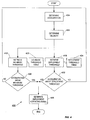
- FIG. 4 includes a flow chart 400 that further illustrates processes that occur in some embodiments including process that maybe carried out by software, firmware, or hardware.
- the sensors sense accelerations and other parameters. This is shown at block 404.
- Analyzed values such as the relative velocity are determined from the unanalyzed values at block 408 using transformations such as integration in the case of velocity, double integration in the case of relative displacement, frequency filtering in the case of filtered acceleration, absolute valuing in the case of a power related value, and the like.
- the analyzed value is then used as a control value to retrieve the no-abuse threshold 312 at block 412, and the deployment threshold 362, as shown at block 416.
- the thresholds 312 and 362 are stored in the memory 204 as look-up-tables 420 and 424 respectively, in some embodiments. Once these thresholds 312 and 362 have been retrieved, the unanalyzed value is compared with the thresholds 312 and 362, as shown at blocks 428 and 432, respectively, and simultaneously depending on the applications at hand. When the unanalyzed value is above both thresholds 312 and 362, a deployment signal is generated as shown at block 436, which in turn activates the restraint device 208. However, if the unanalyzed value is below either one of the thresholds 312 and 362, the restraint device is disabled, and the block 404 is repeated.
Abstract
Description
- Embodiments of the invention relate to vehicle control systems, and more particularly to a vehicle control system to deploy an occupant restraint device.
- Restraint devices such as airbags and seatbelts are, in general, actuated during crashes or possible crashes to protect vehicle occupants from injury. The accuracy and timeliness of deployment and actuation are factors in the effectiveness of restraint devices.
- Some restraint devices are controlled using algorithms that process accelerations measured in various locations of a motor vehicle. The measured accelerations are analyzed using various functions such as integration (to yield velocity), a sum of squares of the measured accelerations, slopes of the measured accelerations, and the like. The outputs of the functions are compared to thresholds that may be constant, depending on factors such as time or physical properties like relative velocity. If the thresholds are crossed, restraint devices are deployed.
- A variety of vehicle conditions may be considered when controlling vehicle restraint devices. A "crash" condition (or "deployment crash" condition) exists when a vehicle has experienced an impact or collision above a certain threshold. In a "crash" condition the vehicle experiences forces that warrant the activation of a restraint device. Another type of condition is an "abuse" condition. An "abuse" condition may exist for a variety of reasons. For example, jarring of the vehicle as the vehicle travels over rough roads may cause an abuse condition to exist. Generally, the existence of an abuse condition does not warrant the activation of a restraint device. Yet another type of condition is sometimes referred to as a "no-deployment-crash" condition. In such a condition, the vehicle may have experienced an impact or collision, but the magnitude of the impact or collision is not sufficient to warrant the deployment of an occupant restraint device.
- The inventors have discovered that one deficiency of known technologies is that crash conditions and abuse conditions are often treated the same way. For example, some algorithms tune thresholds used in them such that neither no-deployment-crashes nor abuse conditions will cross any of the thresholds. (In a no-deployment-crash, the restraint device should not been deployed.) As a result, abuse conditions can adversely impact deployment time during crashes. That is, both abuse and crash conditions are compared to the same thresholds. In such a case, the restraint devices may be deployed when the vehicle is simply experiencing abuse conditions. Or, the restraint devices may be disabled even when the vehicle is experiencing a crash condition because of the inaccuracy of the combined thresholds.
- In one embodiment, the invention provides a method of controlling a restraint device in a vehicle. The method includes determining a vehicle condition that has a value, and retrieving an abuse condition threshold and a deployment condition threshold based on the value of the determined condition. The method then includes generating a restraint device activation signal when the value of the determined condition is below the abuse condition threshold and above the deployment condition threshold.
- Another embodiment of the invention provides a method of controlling a restraint device in a vehicle. The method includes sensing an acceleration of the vehicle, determining a vehicle signal based on the acceleration, and retrieving an abuse condition threshold and a deployment condition threshold based on the acceleration and the vehicle signal. The method also includes comparing a value of the vehicle signal with the abuse condition threshold and the deployment condition threshold, and generating an activation signal based on the comparison.
- Another embodiment provides a method of controlling a restraint device that includes sensing an acceleration of a vehicle, analyzing the acceleration with at least two independent thresholds, and activating the restraint device when the analyzed acceleration exceeds the at least two independent thresholds.
- Yet another embodiment provides an apparatus for controlling a restraint device in a vehicle. The apparatus includes a sensor configured to sense a vehicle condition having values that are indicative of vehicle accelerations. The apparatus also includes a comparator that compares the value with at least two independent thresholds to produce a comparator output, and a signal generator coupled to the comparator. The signal generator generates a deployment signal when the comparator output exceeds the at least two independent thresholds.
- Still another embodiment provides a vehicle. The vehicle includes a restraint device, a sensor to sense a plurality of values indicative of vehicle accelerations, and a processing unit to compare the values indicative of vehicle accelerations with an abuse condition threshold and an independent deployment condition threshold. The processing unit generates a deployment signal when the value is below the abuse condition threshold and above the deployment condition threshold. The vehicle also includes a restraint device that can be deployed upon receiving the deployment signal.
- Other features and advantages of embodiments will become apparent to those skilled in the art upon review of the following detailed description, claims, and drawings.
- In the drawings:
- FIG. 1
- shows a schematic plan view of a vehicle;
- FIG. 2
- shows a block diagram of a control system in the vehicle in FIG. 1;
- FIG.3A
- is a graph of an abuse condition threshold;
- FIG. 3B
- a graph of a deployment condition threshold; and
- FIG. 4
- is a flow chart of processing carried out in embodiments of the invention.
- Before any embodiments of the invention are explained in detail, it is to be understood that the invention is not limited in its application to the details of construction and the arrangement of components set forth in the following description or illustrated in the following drawings. The invention is capable of other embodiments and of being practiced or of being carried out in various ways. Also, it is to be understood that the phraseology and terminology used herein is for the purpose of description and should not be regarded as limiting. The use of "including," "comprising," or "having" and variations thereof herein is meant to encompass the items listed thereafter and equivalents thereof as well as additional items. Unless limited otherwise, the terms "connected," "coupled," and "mounted" and variations thereof herein are used broadly and encompass direct and indirect connections, couplings, and mountings. In addition, the terms "connected" and "coupled" and variations thereof are not restricted to physical or mechanical connections or couplings.
- FIG. 1 shows a schematic plan view of an
exemplary vehicle 100. Thevehicle 100 has fourwheels wheels axles wheel speed sensors wheel speed sensors vehicle 100 also includes other sensors such as afront bumper sensor 120, aback bumper sensor 124, a plurality ofside impact sensors 128, and accelerometers oracceleration sensors wheel speed sensors front bumper sensor 120, theback bumper sensor 124, the plurality ofside impact sensors 128, and thesensors sensors ECU 116. Other types of sensors such as thermal sensors can also be used in thevehicle 100. - The
vehicle 100 also includes a plurality of restraint devices such asfront airbags 132 andside airbags 136. Although FIG. 1 shows only airbag restraint devices, other types of restraint devices such as seatbelt tensioners, and head and torso airbags can also be used in thevehicle 100. - In one embodiment, a control system 200 (FIG. 2) is used to separate non-deployment crash conditions from deployment crash conditions. The
control system 200 receives its input from asensor array 204 that includes thewheel speed sensors front bumper sensor 120, theback bumper sensor 124, theside impact sensors 128, and thesensors ECU 116 in block diagram format. Once the outputs from thesensor array 204 have been processed by theECU 116, a restraint device 208 can be deployed. - In one embodiment, each of the
sensors vehicle 100. For example, thesensors vehicle 100. In some embodiments, thesensors vehicle 100. Sensed motions are then transduced and converted into signals that are indicative of acceleration of thevehicle 100. If thesensors sensors front bumper sensor 120, theback bumper sensor 124, the side-impact sensors 128 can be used to detect or sense events such as crashes and collisions. Values of the signals output by thesensors sensor array 204 are referred to as sensed values, or values hereinafter. - The
ECU 116 includes aprocessor 212 that receives the values from thesensor array 204. Theprocessor 212 then processes the values according to a program stored in amemory 216. Although thememory 216 is shown as being external to theprocessor 212, thememory 216 can also be internal to theprocessor 212. Furthermore, theprocessor 212 can be a general-purpose micro-controller, a general-purpose microprocessor, a dedicated microprocessor or controller, a signal processor, an application-specific-integrated circuit ("ASIC"), or the like. In some embodiments, thecontrol system 200 and its functions described are implemented in a combination of firmware, software, hardware, and the like. To be more specific, as illustrated in FIG. 2, theprocessor 212 communicates with other modules (discussed below). The modules are illustrated as if they were implemented in hardware. However, the functionality of these modules could be implemented in software, and that software could, for example, be stored in thememory 216 and executed by theprocessor 212. - The
exemplary ECU 116 includes ananalyzer 220 that converts, filters or transforms the values generated by thesensor array 204 from one form to another depending on the application at hand. For example, when the values generated by thesensor array 204 are indicative of an acceleration of thevehicle 100, theanalyzer 220 converts the acceleration value to values such as transformed acceleration. For another example, theanalyzer 220 can filter the accelerations into filtered accelerations that may be indicative of a relative velocity of thevehicle 100. For yet another example, theanalyzer 220 can transform the accelerations into a value that is indicative of energy dissipated in thevehicle 100 during the crash. Other transformed values include relative distance displacement, quantized acceleration, absolute-valued acceleration, filtered acceleration, and the like. In some embodiments, the relative velocity of the vehicle is typically determined or obtained by integrating the acceleration detected. Although theanalyzer 220 is shown being external to theprocessor 212, theanalyzer 220 can also be internal as a software or hardware module of theprocessor 212. - Once the values from the
sensor array 204 have been analyzed in theanalyzer 220, either one or both of the analyzed values and the unanalyzed values are used to retrieve thresholds stored in thememory 216. For example, when the unanalyzed values and the analyzed values represent acceleration and velocity respectively, the acceleration and velocity are then used to retrieve a no-abuse condition threshold (or an abuse condition threshold that is similar in nature), and a deployment threshold, detailed hereinafter. - Referring back to FIG. 2, the
ECU 116 also includes acomparator 224 that compares the unanalyzed value with a no-abuse threshold 312 (FIG. 3A) retrieved from thememory 216 based on the analyzed value with a deployment condition threshold 362 (FIG. 3B) retrieved from thememory 216 also based on the analyzed value, as discussed earlier. The outputs of these comparisons are fed to asignal generator 228. The outputs of the comparisons are further compared. When the unanalyzed value corresponding to the analyzed value is above the no-abuse threshold 312 and above thedeployment condition threshold 362, thesignal generator 228 generates a deployment signal to activate the restraint device 208. Otherwise, when the unanalyzed value corresponding to the analyzed value is either below the no-abuse threshold 312 or below thedeployment condition threshold 362, thesignal generator 228 generates a disabling signal that disables the restraint device 208. - In some embodiments, the
signal generator 228 will only generate an activating signal or deployment signal when the unanalyzed value is above both retrieved thresholds, and will not generate any disabling signal otherwise. In this way, other deployment techniques can also be used to activate the restraint devices. For example, in yet some other embodiments, thesignal generator 228 can also generate the activating signal or deployment signal based on a combination of signals generated by other deployment algorithms and the outputs of thecomparator 224. That is, signals from additional deployment techniques are combined and processed in thesignal generator 228 to arrive at a final deployment decision. - In general, the no-abuse condition threshold separates an abuse condition that does not require a restraint device deployment from a no-abuse condition that may require the deployment of a restraint device. FIG. 3A shows a no-abuse
condition threshold plot 300. The analyzed values such as the relative velocities are measured along anx-axis 304 and the unanalyzed values such as the accelerations are measured along a y-axis 308. No-abuse threshold curve 312 generally separates anabuse condition curve 316 from a no-abuse crash condition 320. Theabuse condition curve 316 typically has high oscillatory acceleration peaks. Therefore, the magnitude of the relative velocity is relatively low. The no-abusecrash condition curve 320 typically has no or minimal oscillatory acceleration which results in a relative velocity even for small collision speeds. The no-abuse crash condition 320 therefore crosses the decreasing no-abuse threshold curve 312 while theabuse condition curve 316 does not. If the no-abuse threshold curve is crossed, a no-abuse flag is set. The no-abuse flag is represented by a no-abuse step function 324 in FIG. 3A. During vehicle operation, an acceleration (or deceleration) is detected. A relative velocity is thereafter obtained from the detected acceleration, in a manner that is detailed hereinafter. If the detected acceleration corresponding to the relative velocity is above the no-abuse threshold curve 312, the no-abuse condition is recognized, and the no-abuse flag is set. In general, the no-abuse threshold curve 312 is dynamically determined or measured from the analyzed values sensed over different times, the analyzed values generated from the unanalyzed values, and the like. For example, a first analyzed value can be obtained from determining a plurality of unanalyzed values over a first period of time, while a second analyzed value can be obtained from the unanalyzed values over a second period of time. In this way, the analyzed values determined from the two unanalyzed values can be different, thereby yielding different thresholds. - Similarly, FIG. 3B shows a deployment
condition threshold plot 350. The analyzed values such as the relative velocities are measured along asecond x-axis 354, and the unanalyzed values such as the accelerations are measured along a second y-axis 358. An increasingdeployment threshold curve 362 separates anon-deployment crash curve 366 from adeployment crash curve 370. If a crash occurs, a crash acceleration (or deceleration) is detected. A relative velocity is obtained from the detected acceleration, detailed hereinafter. If the detected acceleration corresponding to the relative velocity is above thedeployment threshold curve 362, a deployment condition is recognized, and a deployment flag is set. The deployment flag is represented by adeployment step function 374 in FIG. 3B. Furthermore, since the twothresholds abuse condition curve 316 crosses the deployment threshold curve, thedeployment flag 374 is not set, because the abuse conditions will be correctly identified by the no-abuse threshold plot 300 as an abuse condition. Similar to the no-abuse threshold curve 312, thedeployment threshold curve 362 is dynamically determined or measured from the unanalyzed values sensed over different times, the analyzed values generated from the unanalyzed values, and the like. - Various unanalyzed values and analyzed values can be used in establishing the
thresholds - As another example, the relative velocity or the filtered acceleration can be plotted against a crash time (measured from the beginning of the crash to the end of the crash) as a control value with the thresholds based on the crash time. Other examples for the unanalyzed and analyzed values include the relative displacement as determined by double integration of the measured acceleration. The displacement can also be plotted against the filtered acceleration or the relative velocity as control values.
- It is also possible to use different unanalyzed and analyzed values in the no-
abuse condition threshold 312 and thedeployment condition threshold 362. An example can be a filtered acceleration, in which the acceleration is filtered with different filter frequencies for use in the no-abuse condition threshold 312 and thedeployment condition threshold 362. Features or values specifically suitable and/or tuned to separate abuse conditions from crash conditions regardless of their severity may also be employed in the no-abuse condition threshold 312. Similarly, different unanalyzed and analyzed values suitable to identify the severity of crashes and to separate non-deployment crashes from deployment crashes regardless of the abuse conditions can also be used to establish thedeployment condition threshold 362. - FIG. 4 includes a
flow chart 400 that further illustrates processes that occur in some embodiments including process that maybe carried out by software, firmware, or hardware. As noted, the sensors sense accelerations and other parameters. This is shown atblock 404. Analyzed values such as the relative velocity are determined from the unanalyzed values atblock 408 using transformations such as integration in the case of velocity, double integration in the case of relative displacement, frequency filtering in the case of filtered acceleration, absolute valuing in the case of a power related value, and the like. The analyzed value is then used as a control value to retrieve the no-abuse threshold 312 atblock 412, and thedeployment threshold 362, as shown atblock 416. Thethresholds memory 204 as look-up-tables 420 and 424 respectively, in some embodiments. Once thesethresholds thresholds blocks thresholds block 436, which in turn activates the restraint device 208. However, if the unanalyzed value is below either one of thethresholds block 404 is repeated. - Various features of the invention are set forth in the following claims.
Claims (32)
- A method of controlling a restraint device in a vehicle, the method comprising:determining a condition of the vehicle, the determined condition having a value;retrieving a no-abuse condition threshold based on the value of the determined condition;retrieving a deployment condition threshold based on the value of the determined condition; andgenerating a restraint device activation signal when the value of the determined condition is above the abuse condition threshold and the deployment condition threshold.
- The method of claim 1, further comprising:establishing the abuse condition threshold; andindependently establishing the deployment condition threshold.
- The method of claim 1, wherein determining the condition of the vehicle further comprises:sensing an acceleration of the vehicle; anddetermining a velocity of the vehicle from the acceleration.
- The method of claim 1, further comprising transforming the condition into at least one of an acceleration, a velocity, a distance displacement of the vehicle, and a value indicative of energy dissipated in the vehicle.
- The method of claim 1, wherein the value comprises an acceleration of the vehicle, the method further comprising integrating the acceleration of the determined condition.
- The method of claim 1, further comprising generating a restraint device disable signal when the value of the determined condition is either below the no-abuse condition threshold or below the deployment condition threshold.
- The method of claim 1, further comprising activating a restraint device if the restraint device activation signal is generated.
- A method of controlling a restraint device in a vehicle, the method comprising:sensing an acceleration of the vehicle; determining a vehicle signal based on the acceleration;retrieving a no-abuse condition threshold based on the acceleration and the vehicle signal;retrieving a deployment condition threshold based on the acceleration and the vehicle signal;comparing a value of the vehicle signal with the no-abuse condition threshold and the deployment condition threshold; andgenerating a deployment signal when the value of the determined condition is above the no-abuse condition threshold and the deployment condition threshold.
- The method of claim 8, further comprising activating the restraint device.
- The method of claim 8, further comprising integrating the sensed acceleration.
- The method of claim 8, wherein the vehicle signal comprises at least one of a filtered acceleration of the vehicle, a velocity of the vehicle, a distance displacement of the vehicle, and a value indicative of energy dissipated in the vehicle.
- The method of claim 8, further comprising:establishing the no-abuse condition threshold; andindependently establishing the deployment condition threshold.
- The method of claim 8, further comprising generating a disabling signal to the restraint device when the value of the determined condition is either below the no-abuse condition threshold or below the deployment condition threshold.
- The method of claim 8, further comprising activating the restraint device if the deployment signal is generated.
- A method of controlling a restraint device in a vehicle, the method comprising:sensing an acceleration of the vehicle;analyzing the acceleration with at least two independent thresholds; andgenerating a restraint device activation signal when the analyzed acceleration exceeds the at least two independent thresholds.
- The method of claim 15, further comprising determining from the acceleration at least one of a velocity, a distance displacement of the vehicle, and a value indicative of energy dissipated in the vehicle.
- The method of claim 15, wherein the least two independent thresholds comprise a no-abuse condition threshold and a deployment condition threshold.
- The method of claim 15, wherein analyzing the acceleration further comprises:retrieving the least two independent thresholds based on the acceleration;determining a vehicle signal based on the acceleration; andcomparing a value of the vehicle signal with the least two independent thresholds.
- The method of claim 15, further comprising generating a restraint device disable signal when the analyzed acceleration is below is below one of the at least two independent thresholds.
- The method of claim 15, further comprising activating the restraint device when the activation signal is generated.
- An apparatus for controlling a restraint device in a vehicle, the apparatus comprising:a sensor configured to sense a vehicle condition having a value indicative of a vehicle acceleration;a comparator coupled to the sensor, and configured to compare the value indicative of the vehicle acceleration with at least two independent thresholds to produce a comparator output; anda signal generator coupled to the comparator, and configured to create an activation signal when the comparator output exceeds the at least two independent thresholds.
- The apparatus of claim 21, further comprising a memory capable of storing the at least two independent thresholds.
- The apparatus of claim 21, wherein the at least two independent thresholds comprise a no-abuse condition threshold and an independent deployment condition threshold.
- The apparatus of claim 23, wherein the signal generator activates the restraint device when the comparator output is above the no-abuse condition threshold and above the deployment condition threshold, and disables the restraint device when the comparator output is either below the no-abuse condition threshold or below the deployment condition threshold.
- The apparatus of claim 21, further comprising an analyzer configured to determine from the value at least one of an acceleration, a velocity, a distance displacement of the vehicle, and a value indicative of energy dissipated in the vehicle.
- The apparatus of claim 21, wherein the analyzer comprises an integrator.
- The apparatus of claim 21, wherein the sensor comprises an accelerometer.
- The apparatus of claim 21, further comprising a processor coupled to the sensor, and configured to receive the value and to retrieve the at least two independent thresholds.
- A vehicle comprising:a sensor coupled to the vehicle, and configured to sense a vehicle condition having a value indicative of vehicle acceleration;an electronic processing unit coupled to the sensor, having a comparator, the comparator comparing the value with a no-abuse condition threshold and an independent deployment condition threshold, the electronic processing unit generating a deployment signal when the value is above the no-abuse condition threshold and above the deployment condition threshold; anda restraint device coupled to the electronic processing unit, and configured to be deployed upon receiving the deployment signal.
- The vehicle of claim 29, wherein the electronic processing unit further comprises a memory capable of storing the no-abuse condition threshold and the independent deployment condition threshold.
- The vehicle of claim 29, wherein the comparator generates a comparator output, and wherein the electronic processing unit disables the restraint device when the comparator output is either below the no-abuse condition threshold or below the deployment condition threshold.
- The apparatus of claim 29, wherein the electronic processing unit further comprises an analyzer configured to determine from the value indicative of vehicle acceleration at least one of a filtered acceleration, a velocity, a distance displacement of the vehicle, and a value indicative of energy dissipated in the vehicle.
Applications Claiming Priority (1)
| Application Number | Priority Date | Filing Date | Title |
|---|---|---|---|
| US10/919,651 US8186711B2 (en) | 2004-08-17 | 2004-08-17 | Separation of abuse conditions and crash events to control occupant restraint devices |
Publications (3)
| Publication Number | Publication Date |
|---|---|
| EP1637404A2 true EP1637404A2 (en) | 2006-03-22 |
| EP1637404A3 EP1637404A3 (en) | 2006-09-20 |
| EP1637404B1 EP1637404B1 (en) | 2007-12-05 |
Family
ID=35432361
Family Applications (1)
| Application Number | Title | Priority Date | Filing Date |
|---|---|---|---|
| EP05016730A Expired - Fee Related EP1637404B1 (en) | 2004-08-17 | 2005-08-02 | Separation of abuse conditions and crash events to control occupant restraint devices |
Country Status (4)
| Country | Link |
|---|---|
| US (1) | US8186711B2 (en) |
| EP (1) | EP1637404B1 (en) |
| JP (1) | JP4833609B2 (en) |
| DE (1) | DE602005003622T2 (en) |
Families Citing this family (2)
| Publication number | Priority date | Publication date | Assignee | Title |
|---|---|---|---|---|
| DE102008042399B4 (en) | 2008-09-26 | 2019-06-13 | Robert Bosch Gmbh | Restraint system for a vehicle |
| US9969343B2 (en) * | 2015-07-24 | 2018-05-15 | Robert Bosch Gmbh | Methods and systems for managing an electrical connection between a power regulating device and an energy storage device included in a vehicle |
Citations (3)
| Publication number | Priority date | Publication date | Assignee | Title |
|---|---|---|---|---|
| DE4223562A1 (en) * | 1992-07-17 | 1993-09-23 | Daimler Benz Ag | Vehicle passenger safety system acceleration triggering - comparing integrated and discriminated acceleration signal with threshold derived from filtering of discriminated signal. |
| US6157880A (en) * | 1996-03-14 | 2000-12-05 | Autoliv Developement Ab | Crash detector responsive to a side impact |
| DE10050956A1 (en) * | 2000-10-13 | 2002-05-02 | Bayerische Motoren Werke Ag | Method for triggering at least one restraint |
Family Cites Families (28)
| Publication number | Priority date | Publication date | Assignee | Title |
|---|---|---|---|---|
| DE2222038C3 (en) * | 1972-05-05 | 1978-07-06 | Messerschmitt-Boelkow-Blohm Gmbh, 8000 Muenchen | Test circuit for the triggering device of a safety device used to protect the occupants of a vehicle during an accident |
| US4638179A (en) * | 1984-03-31 | 1987-01-20 | Robert Bosch Gmbh | Extended response trigger circuit |
| JP2570916B2 (en) | 1991-04-15 | 1997-01-16 | 株式会社デンソー | Control device for vehicle safety device |
| DE4117811A1 (en) * | 1991-05-31 | 1992-12-03 | Messerschmitt Boelkow Blohm | Motor vehicle impact detection method for activating occupant safety system - measuring acceleration and deceleration, integrating, subtracting previous speed value and comparing with threshold |
| US5339242A (en) * | 1991-11-26 | 1994-08-16 | Delco Electronics Corp. | Method and apparatus for vehicle crash discrimination based on oscillation and energy content |
| US5436838A (en) * | 1992-09-21 | 1995-07-25 | Nec Corporation | Crash/non-crash discrimination using frequency components of acceleration uniquely generated upon crash impact |
| US5418722A (en) * | 1994-03-04 | 1995-05-23 | Delco Electronics Corporation | SIR deployment method with rough road immunity |
| US5483449A (en) * | 1994-03-31 | 1996-01-09 | Delco Electronics Corporation | Inflatable restraint system and method of controlling deployment thereof |
| US5668740A (en) * | 1994-12-20 | 1997-09-16 | General Motors Corporation | Method for detecting a rough road surface |
| JP3014313B2 (en) * | 1995-12-25 | 2000-02-28 | 富士通テン株式会社 | Airbag collision detection device |
| US6070113A (en) * | 1996-06-21 | 2000-05-30 | Automotive Systems Laboratory, Inc. | Hybrid vehicle crash discrimination system |
| JP3333813B2 (en) * | 1996-11-20 | 2002-10-15 | トヨタ自動車株式会社 | Startup control device for occupant protection device |
| JP3452012B2 (en) * | 1996-11-20 | 2003-09-29 | トヨタ自動車株式会社 | Activation control device for occupant protection device |
| KR100363423B1 (en) * | 1997-05-16 | 2002-11-30 | 오토리브 재팬 리미티드 | Actuation controller for air bag device |
| JPH11115679A (en) * | 1997-10-15 | 1999-04-27 | Tokai Rika Co Ltd | Air bag device |
| JP3910293B2 (en) * | 1998-03-12 | 2007-04-25 | カルソニックカンセイ株式会社 | Side airbag unit |
| US6154698A (en) * | 1998-07-30 | 2000-11-28 | Delco Electronics Corp. | Supplemental restraint deployment method providing rough road immunity |
| US5964817A (en) * | 1998-11-09 | 1999-10-12 | Delco Electronics Corp. | Impact characterizing deployment control method for an automotive restraint system |
| US5969599A (en) * | 1998-11-09 | 1999-10-19 | Delco Electronics Corp. | Restraint deployment control method having an adaptable deployment threshold |
| US6198387B1 (en) * | 1998-11-09 | 2001-03-06 | Delphi Technologies, Inc. | Restraint deployment control with central and frontal crash sensing |
| JP3772629B2 (en) * | 2000-03-02 | 2006-05-10 | トヨタ自動車株式会社 | Rough road determination device, rough road determination method, activation device and activation method for occupant protection device |
| JP3487279B2 (en) | 2000-10-02 | 2004-01-13 | トヨタ自動車株式会社 | Startup control device for occupant protection device |
| US6553294B1 (en) * | 2000-10-16 | 2003-04-22 | Delphi Technologies, Inc. | Dual stage occupant restraint deployment control for motor vehicle |
| US6439007B1 (en) * | 2000-11-28 | 2002-08-27 | Trw Inc. | Enhanced occupant spring mass model for use with an actuatable restraint system including compensating for monotonicity of misuse conditions |
| US6529810B2 (en) * | 2001-04-09 | 2003-03-04 | Trw Inc. | Method and apparatus for controlling an actuatable restraining device using switched thresholds based on transverse acceleration |
| DE10138764C1 (en) * | 2001-06-06 | 2002-10-31 | Bosch Gmbh Robert | Frontal impact detection system for use on motor vehicle uses forward-mounted longitudinal acceleration sensor and rearward-mounted longitudinal and lateral acceleration sensor |
| ES2231713T3 (en) * | 2001-06-06 | 2005-05-16 | Robert Bosch Gmbh | DEVICE FOR DETECTING A FRONT IMPACT ON A VEHICLE. |
| JP4076849B2 (en) * | 2002-12-11 | 2008-04-16 | 株式会社ケーヒン | Start-up control device for airbag device |
-
2004
- 2004-08-17 US US10/919,651 patent/US8186711B2/en active Active
-
2005
- 2005-08-02 DE DE602005003622T patent/DE602005003622T2/en active Active
- 2005-08-02 EP EP05016730A patent/EP1637404B1/en not_active Expired - Fee Related
- 2005-08-16 JP JP2005235791A patent/JP4833609B2/en not_active Expired - Fee Related
Patent Citations (3)
| Publication number | Priority date | Publication date | Assignee | Title |
|---|---|---|---|---|
| DE4223562A1 (en) * | 1992-07-17 | 1993-09-23 | Daimler Benz Ag | Vehicle passenger safety system acceleration triggering - comparing integrated and discriminated acceleration signal with threshold derived from filtering of discriminated signal. |
| US6157880A (en) * | 1996-03-14 | 2000-12-05 | Autoliv Developement Ab | Crash detector responsive to a side impact |
| DE10050956A1 (en) * | 2000-10-13 | 2002-05-02 | Bayerische Motoren Werke Ag | Method for triggering at least one restraint |
Also Published As
| Publication number | Publication date |
|---|---|
| EP1637404A3 (en) | 2006-09-20 |
| JP4833609B2 (en) | 2011-12-07 |
| US20060038387A1 (en) | 2006-02-23 |
| DE602005003622T2 (en) | 2008-04-10 |
| EP1637404B1 (en) | 2007-12-05 |
| JP2006056506A (en) | 2006-03-02 |
| DE602005003622D1 (en) | 2008-01-17 |
| US8186711B2 (en) | 2012-05-29 |
Similar Documents
| Publication | Publication Date | Title |
|---|---|---|
| EP1783006B2 (en) | Vehicle restraint device control method and apparatus using dynamically determined threshold | |
| US6725141B2 (en) | Method of triggering restraint means in a motor vehicle | |
| US9650006B2 (en) | Method and apparatus for controlling an actuatable restraining device using multi-region enhanced discrimination | |
| EP0785112B1 (en) | Method and apparatus for sensing impact crash conditions with safing function | |
| US6915196B2 (en) | Method for operating a vehicle crash safety system in a vehicle having a pre-crash sensing system and countermeasure systems | |
| JP3436185B2 (en) | Activation control device for occupant protection device | |
| KR100663794B1 (en) | Method and apparatus for determining symmetric and asymmetric crash events with improved misuse margins | |
| EP1559616A1 (en) | Vehicle rollover detection using dual-axis acceleration sensing | |
| US7278657B1 (en) | Method and apparatus for controlling an actuatable occupant protection device using an ultrasonic sensor | |
| EP1717108B1 (en) | System and method for sensing soil- and curb-tripped rollover events | |
| US8118130B2 (en) | Method and apparatus for controlling an actuatable restraining device using XY crush-zone satellite accelerometers | |
| KR101391381B1 (en) | Method and apparatus for controlling an actuatable restraint device using a side pressure sensor | |
| US9937887B2 (en) | Method and apparatus for providing a safing function in a restraining system | |
| EP1637404B1 (en) | Separation of abuse conditions and crash events to control occupant restraint devices | |
| US6212454B1 (en) | Method and apparatus for disabling an actuatable restraint based on determined crash velocity and displacement | |
| WO2010025206A2 (en) | Method and apparatus for controlling an actuatable safety device | |
| EP1566315B1 (en) | A safety logic unit for vehicle rollover detection systems and a method for determining near rollover situations | |
| JP2003043060A (en) | Collision judgment apparatus for vehicle | |
| JP2008528377A (en) | Safety system | |
| JP3876111B2 (en) | Vehicle collision determination device | |
| JP2008247242A (en) | Driving device and drive judging method for occupant protecting device | |
| WO2002024489A1 (en) | A crash assessment and classification device | |
| JPH04103450A (en) | Crew protection device for vehicle |
Legal Events
| Date | Code | Title | Description |
|---|---|---|---|
| PUAI | Public reference made under article 153(3) epc to a published international application that has entered the european phase |
Free format text: ORIGINAL CODE: 0009012 |
|
| AK | Designated contracting states |
Kind code of ref document: A2 Designated state(s): AT BE BG CH CY CZ DE DK EE ES FI FR GB GR HU IE IS IT LI LT LU LV MC NL PL PT RO SE SI SK TR |
|
| AX | Request for extension of the european patent |
Extension state: AL BA HR MK YU |
|
| PUAL | Search report despatched |
Free format text: ORIGINAL CODE: 0009013 |
|
| AK | Designated contracting states |
Kind code of ref document: A3 Designated state(s): AT BE BG CH CY CZ DE DK EE ES FI FR GB GR HU IE IS IT LI LT LU LV MC NL PL PT RO SE SI SK TR |
|
| AX | Request for extension of the european patent |
Extension state: AL BA HR MK YU |
|
| 17P | Request for examination filed |
Effective date: 20070315 |
|
| 17Q | First examination report despatched |
Effective date: 20070416 |
|
| AKX | Designation fees paid |
Designated state(s): DE ES FR GB |
|
| GRAP | Despatch of communication of intention to grant a patent |
Free format text: ORIGINAL CODE: EPIDOSNIGR1 |
|
| GRAS | Grant fee paid |
Free format text: ORIGINAL CODE: EPIDOSNIGR3 |
|
| GRAA | (expected) grant |
Free format text: ORIGINAL CODE: 0009210 |
|
| AK | Designated contracting states |
Kind code of ref document: B1 Designated state(s): DE ES FR GB |
|
| REG | Reference to a national code |
Ref country code: GB Ref legal event code: FG4D |
|
| REF | Corresponds to: |
Ref document number: 602005003622 Country of ref document: DE Date of ref document: 20080117 Kind code of ref document: P |
|
| PG25 | Lapsed in a contracting state [announced via postgrant information from national office to epo] |
Ref country code: ES Free format text: LAPSE BECAUSE OF FAILURE TO SUBMIT A TRANSLATION OF THE DESCRIPTION OR TO PAY THE FEE WITHIN THE PRESCRIBED TIME-LIMIT Effective date: 20080316 |
|
| ET | Fr: translation filed | ||
| PLBE | No opposition filed within time limit |
Free format text: ORIGINAL CODE: 0009261 |
|
| STAA | Information on the status of an ep patent application or granted ep patent |
Free format text: STATUS: NO OPPOSITION FILED WITHIN TIME LIMIT |
|
| 26N | No opposition filed |
Effective date: 20080908 |
|
| REG | Reference to a national code |
Ref country code: FR Ref legal event code: PLFP Year of fee payment: 12 |
|
| REG | Reference to a national code |
Ref country code: FR Ref legal event code: PLFP Year of fee payment: 13 |
|
| REG | Reference to a national code |
Ref country code: FR Ref legal event code: PLFP Year of fee payment: 14 |
|
| PGFP | Annual fee paid to national office [announced via postgrant information from national office to epo] |
Ref country code: FR Payment date: 20200820 Year of fee payment: 16 Ref country code: GB Payment date: 20200825 Year of fee payment: 16 |
|
| PGFP | Annual fee paid to national office [announced via postgrant information from national office to epo] |
Ref country code: DE Payment date: 20211025 Year of fee payment: 17 |
|
| GBPC | Gb: european patent ceased through non-payment of renewal fee |
Effective date: 20210802 |
|
| PG25 | Lapsed in a contracting state [announced via postgrant information from national office to epo] |
Ref country code: GB Free format text: LAPSE BECAUSE OF NON-PAYMENT OF DUE FEES Effective date: 20210802 Ref country code: FR Free format text: LAPSE BECAUSE OF NON-PAYMENT OF DUE FEES Effective date: 20210831 |
|
| REG | Reference to a national code |
Ref country code: DE Ref legal event code: R119 Ref document number: 602005003622 Country of ref document: DE |
|
| PG25 | Lapsed in a contracting state [announced via postgrant information from national office to epo] |
Ref country code: DE Free format text: LAPSE BECAUSE OF NON-PAYMENT OF DUE FEES Effective date: 20230301 |