EP1637309A1 - Method and apparatus for overmolding a gear onto a shaft - Google Patents
Method and apparatus for overmolding a gear onto a shaft Download PDFInfo
- Publication number
- EP1637309A1 EP1637309A1 EP05076994A EP05076994A EP1637309A1 EP 1637309 A1 EP1637309 A1 EP 1637309A1 EP 05076994 A EP05076994 A EP 05076994A EP 05076994 A EP05076994 A EP 05076994A EP 1637309 A1 EP1637309 A1 EP 1637309A1
- Authority
- EP
- European Patent Office
- Prior art keywords
- shaft
- flats
- gear
- accordance
- end portion
- Prior art date
- Legal status (The legal status is an assumption and is not a legal conclusion. Google has not performed a legal analysis and makes no representation as to the accuracy of the status listed.)
- Withdrawn
Links
Images


Classifications
-
- F—MECHANICAL ENGINEERING; LIGHTING; HEATING; WEAPONS; BLASTING
- F16—ENGINEERING ELEMENTS AND UNITS; GENERAL MEASURES FOR PRODUCING AND MAINTAINING EFFECTIVE FUNCTIONING OF MACHINES OR INSTALLATIONS; THERMAL INSULATION IN GENERAL
- F16H—GEARING
- F16H57/00—General details of gearing
- F16H57/0018—Shaft assemblies for gearings
- F16H57/0025—Shaft assemblies for gearings with gearing elements rigidly connected to a shaft, e.g. securing gears or pulleys by specially adapted splines, keys or methods
-
- B—PERFORMING OPERATIONS; TRANSPORTING
- B29—WORKING OF PLASTICS; WORKING OF SUBSTANCES IN A PLASTIC STATE IN GENERAL
- B29C—SHAPING OR JOINING OF PLASTICS; SHAPING OF MATERIAL IN A PLASTIC STATE, NOT OTHERWISE PROVIDED FOR; AFTER-TREATMENT OF THE SHAPED PRODUCTS, e.g. REPAIRING
- B29C45/00—Injection moulding, i.e. forcing the required volume of moulding material through a nozzle into a closed mould; Apparatus therefor
- B29C45/14—Injection moulding, i.e. forcing the required volume of moulding material through a nozzle into a closed mould; Apparatus therefor incorporating preformed parts or layers, e.g. injection moulding around inserts or for coating articles
- B29C45/14311—Injection moulding, i.e. forcing the required volume of moulding material through a nozzle into a closed mould; Apparatus therefor incorporating preformed parts or layers, e.g. injection moulding around inserts or for coating articles using means for bonding the coating to the articles
-
- F—MECHANICAL ENGINEERING; LIGHTING; HEATING; WEAPONS; BLASTING
- F02—COMBUSTION ENGINES; HOT-GAS OR COMBUSTION-PRODUCT ENGINE PLANTS
- F02D—CONTROLLING COMBUSTION ENGINES
- F02D9/00—Controlling engines by throttling air or fuel-and-air induction conduits or exhaust conduits
- F02D9/08—Throttle valves specially adapted therefor; Arrangements of such valves in conduits
- F02D9/10—Throttle valves specially adapted therefor; Arrangements of such valves in conduits having pivotally-mounted flaps
- F02D9/107—Manufacturing or mounting details
-
- F—MECHANICAL ENGINEERING; LIGHTING; HEATING; WEAPONS; BLASTING
- F02—COMBUSTION ENGINES; HOT-GAS OR COMBUSTION-PRODUCT ENGINE PLANTS
- F02D—CONTROLLING COMBUSTION ENGINES
- F02D9/00—Controlling engines by throttling air or fuel-and-air induction conduits or exhaust conduits
- F02D9/08—Throttle valves specially adapted therefor; Arrangements of such valves in conduits
- F02D9/10—Throttle valves specially adapted therefor; Arrangements of such valves in conduits having pivotally-mounted flaps
- F02D9/1075—Materials, e.g. composites
- F02D9/108—Plastics
-
- B—PERFORMING OPERATIONS; TRANSPORTING
- B29—WORKING OF PLASTICS; WORKING OF SUBSTANCES IN A PLASTIC STATE IN GENERAL
- B29C—SHAPING OR JOINING OF PLASTICS; SHAPING OF MATERIAL IN A PLASTIC STATE, NOT OTHERWISE PROVIDED FOR; AFTER-TREATMENT OF THE SHAPED PRODUCTS, e.g. REPAIRING
- B29C45/00—Injection moulding, i.e. forcing the required volume of moulding material through a nozzle into a closed mould; Apparatus therefor
- B29C45/14—Injection moulding, i.e. forcing the required volume of moulding material through a nozzle into a closed mould; Apparatus therefor incorporating preformed parts or layers, e.g. injection moulding around inserts or for coating articles
- B29C45/14336—Coating a portion of the article, e.g. the edge of the article
-
- B—PERFORMING OPERATIONS; TRANSPORTING
- B29—WORKING OF PLASTICS; WORKING OF SUBSTANCES IN A PLASTIC STATE IN GENERAL
- B29C—SHAPING OR JOINING OF PLASTICS; SHAPING OF MATERIAL IN A PLASTIC STATE, NOT OTHERWISE PROVIDED FOR; AFTER-TREATMENT OF THE SHAPED PRODUCTS, e.g. REPAIRING
- B29C45/00—Injection moulding, i.e. forcing the required volume of moulding material through a nozzle into a closed mould; Apparatus therefor
- B29C45/14—Injection moulding, i.e. forcing the required volume of moulding material through a nozzle into a closed mould; Apparatus therefor incorporating preformed parts or layers, e.g. injection moulding around inserts or for coating articles
- B29C45/14549—Coating rod-like, wire-like or belt-like articles
-
- B—PERFORMING OPERATIONS; TRANSPORTING
- B29—WORKING OF PLASTICS; WORKING OF SUBSTANCES IN A PLASTIC STATE IN GENERAL
- B29K—INDEXING SCHEME ASSOCIATED WITH SUBCLASSES B29B, B29C OR B29D, RELATING TO MOULDING MATERIALS OR TO MATERIALS FOR MOULDS, REINFORCEMENTS, FILLERS OR PREFORMED PARTS, e.g. INSERTS
- B29K2705/00—Use of metals, their alloys or their compounds, for preformed parts, e.g. for inserts
-
- B—PERFORMING OPERATIONS; TRANSPORTING
- B29—WORKING OF PLASTICS; WORKING OF SUBSTANCES IN A PLASTIC STATE IN GENERAL
- B29L—INDEXING SCHEME ASSOCIATED WITH SUBCLASS B29C, RELATING TO PARTICULAR ARTICLES
- B29L2015/00—Gear wheels or similar articles with grooves or projections, e.g. control knobs
- B29L2015/003—Gears
-
- B—PERFORMING OPERATIONS; TRANSPORTING
- B29—WORKING OF PLASTICS; WORKING OF SUBSTANCES IN A PLASTIC STATE IN GENERAL
- B29L—INDEXING SCHEME ASSOCIATED WITH SUBCLASS B29C, RELATING TO PARTICULAR ARTICLES
- B29L2031/00—Other particular articles
- B29L2031/748—Machines or parts thereof not otherwise provided for
- B29L2031/7506—Valves
-
- F—MECHANICAL ENGINEERING; LIGHTING; HEATING; WEAPONS; BLASTING
- F16—ENGINEERING ELEMENTS AND UNITS; GENERAL MEASURES FOR PRODUCING AND MAINTAINING EFFECTIVE FUNCTIONING OF MACHINES OR INSTALLATIONS; THERMAL INSULATION IN GENERAL
- F16H—GEARING
- F16H55/00—Elements with teeth or friction surfaces for conveying motion; Worms, pulleys or sheaves for gearing mechanisms
- F16H55/02—Toothed members; Worms
- F16H55/06—Use of materials; Use of treatments of toothed members or worms to affect their intrinsic material properties
- F16H2055/065—Moulded gears, e.g. inserts therefor
Definitions
- the present invention relates to molding of plastic parts; more particularly, to overmolding of plastic parts onto substrates; and most particularly, to method and apparatus for overmolding a plastic gear onto a gear shaft.
- the rotary valve shaft of an electronically controlled air flow valve for admitting air to an internal combustion engine typically includes a gear mounted onto the end of the shaft.
- a gear mounted onto the end of the shaft For minimizing manufacturing cost and finished weight of the assembly, it is known to form the gear from a injection-moldable polymer such as nylon, and further, to overmold the gear directly onto the end of the shaft.
- the shaft typically is provided with features in the overmolding region, such as a pair of opposed flats, also known in the art as "double D's" in reference to the appearance of the flats in a shaft cross-sectional view.
- the mold is provided with an axial gate for injecting liquid polymer onto the end of the shaft.
- the polymer flows around the end surface to fill the double D voids and then flows primarily from the double D voids circumferentially around the shaft to form the remainder of the gear hub and gear teeth.
- knit lines are formed which differ in polymeric structure and strength from the rest of the injection.
- a shaft for receiving a polymer overmolding of a gear from an axial single-gate mold is provided with a plurality of features for preventing rotation of the molded gear on the shaft.
- the shaft features are in the form of a plurality of axial-direction flats, the number of such flats being greater than two (double D) and preferably four (referred to herein as "quadral D").
- quadrature D a quadraturethane
- Finite element analysis shows that in a four-flat mold and shaft arrangement having a single, axial mold gate, longitudinal knit lines between the D's are virtually non-existent, and polymer in these areas is substantially as strong as polymer elsewhere in the casting.
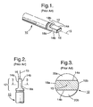
- a prior art shaft 10 includes an end portion 12 formed for receiving an overmolded gear (not shown).
- End portion 12 is basically cylindrical and is provided with first and second opposed flats 14a,14b parallel with shaft axis 15, extending from shaft end 16, and separated by cylindrical inter-flat regions 18a,18b.
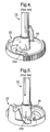
- a polymer gear 22 is shown, having been formed on portion 12 of shaft 10 by conventional injection overmolding using a hub and gear shaped mold (not shown) having an axial gate on axis 15.
- liquid polymer enters the mold via the axial gate, flows over and covers end 16, and axially enters two cylindrical voids 20a,20b formed by cooperation of the cylindrical hub mold and shaft flats 14a,14b.
- These voids are known colloquially in the art as "D"s because of their appearance in cross-section, as shown in FIG. 3.
- Some polymer also flows axially into inter-flat regions 18a,18b, but most of the polymer entering those regions comes circumferentially from voids 20a,20b, resulting in longitudinal knit lines 24a,24b in hub 26 wherein the advancing polymer fronts meet and partially coalesce.
- knit lines 24a,24b can represent zones of weakness in the resulting casting.
- hub knit lines 24a,24b are shown having fractured, under stress load and time of use, into cracks 28a,28b, extending into gear flange 30 and periphery 32, and joining to form catastrophic crack 28c extending across the molded end 34 of hub 26.
- an improved shaft 110 in accordance with the invention includes an end portion 112 formed for receiving an overmolded gear (not shown).
- End portion 112 is basically cylindrical and is provided with first, second, third, and fourth flats 114a,114b,114c,114d parallel with shaft axis 115 preferably at 90° included angles to one another, extending from shaft end 116, and separated by cylindrical inter-flat regions 118a,118b,118c,118d.
- Flats 114a,114b,114c,114d in accordance with the invention need not necessarily be formed at 90° to one another, nor all of the same chordal length, although a currently preferred embodiment is as shown in FIGS. 8 through 10.
- a polymer gear (not shown but understood to be similar to gear 22) is formed on portion 112 of shaft 110 by conventional injection overmolding using a hub and gear shaped mold (not shown) having an axial gate on axis 115, liquid polymer enters the mold via the axial gate, flows over and covers end 116, and axially enters the four cylindrical (quadral D) voids 120a,120b,120c,120d formed by cooperation of the cylindrical hub mold and shaft flats 114a,114b,114c,114d.
Landscapes
- Engineering & Computer Science (AREA)
- Mechanical Engineering (AREA)
- General Engineering & Computer Science (AREA)
- Chemical & Material Sciences (AREA)
- Combustion & Propulsion (AREA)
- Manufacturing & Machinery (AREA)
- Gears, Cams (AREA)
- Injection Moulding Of Plastics Or The Like (AREA)
Abstract
Description
- The present invention relates to molding of plastic parts; more particularly, to overmolding of plastic parts onto substrates; and most particularly, to method and apparatus for overmolding a plastic gear onto a gear shaft.
- It is well known to drive the rotation of a shaft by means of a gear, pulley, or lever arm (referred to herein collectively as a "gear") attached to the end of the shaft. For a simple example, the rotary valve shaft of an electronically controlled air flow valve for admitting air to an internal combustion engine typically includes a gear mounted onto the end of the shaft. For minimizing manufacturing cost and finished weight of the assembly, it is known to form the gear from a injection-moldable polymer such as nylon, and further, to overmold the gear directly onto the end of the shaft. To keep the gear locked onto the shaft and prevent it from loosening and rotating on the shaft during its working lifetime, the shaft typically is provided with features in the overmolding region, such as a pair of opposed flats, also known in the art as "double D's" in reference to the appearance of the flats in a shaft cross-sectional view.
- A weakness is known to arise in such a prior art gear when overmolded onto a shaft in this fashion. Typically, the mold is provided with an axial gate for injecting liquid polymer onto the end of the shaft. The polymer flows around the end surface to fill the double D voids and then flows primarily from the double D voids circumferentially around the shaft to form the remainder of the gear hub and gear teeth. Where the opposing flows from the double D voids meet, knit lines are formed which differ in polymeric structure and strength from the rest of the injection. The inventors believe that, although there is some longitudinal flow of polymer in the regions between the double D voids, most of the material therein enters circumferentially from the double D voids, thus producing pronounced longitudinal knit lines at the interfaces between the opposed circumferential flows. Testing has shown that such knit lines may have up to 50% less tensile strength as compared to casting formed from free-flowing polymer. In use, prior art gears may crack along the knit lines, when loaded torsionally against the shaft, resulting in catastrophic failure of the shaft/gear assembly.
- What is needed in the art is a method and apparatus for overmolding a polymeric gear onto a shaft without creating significant zones of structural weakness in the molded component.
- It is a principal object of the present invention to provide an assembly comprising an overmolded gear on a shaft which maintains the structural integrity of the assembly over its working life.
- Briefly described, a shaft for receiving a polymer overmolding of a gear from an axial single-gate mold is provided with a plurality of features for preventing rotation of the molded gear on the shaft. The shaft features are in the form of a plurality of axial-direction flats, the number of such flats being greater than two (double D) and preferably four (referred to herein as "quadral D"). Finite element analysis shows that in a four-flat mold and shaft arrangement having a single, axial mold gate, longitudinal knit lines between the D's are virtually non-existent, and polymer in these areas is substantially as strong as polymer elsewhere in the casting.
- The present invention will now be described, by way of example, with reference to the accompanying drawings, in which:
- FIG. 1 is an isometric view of a prior art shaft having a double D shaft end portion;
- FIG. 2 is an elevational view of the double D shaft end portion shown in FIG. 1;
- FIG. 3 is a cross-sectional view taken through the double D shaft end portion taken along line 3-3;
- FIG. 4 is a first isometric view of a prior art gear overmolded onto the double D shaft end of the shaft shown in FIGS. 1-3, showing the position of a first knit line;
- FIG. 5 is a second isometric view of the prior art gear shown in FIG. 4, taken at 180° from that view and showing a second and opposite knit line;
- FIG. 6 is a first isometric view of the prior art shaft and gear shown in FIGS. 4-5, showing propagation of a catastrophic crack from the knit lines shown in FIGS. 4-5;
- FIG. 7 is a second isometric view of the opposite side of the gear shown in FIG. 6, showing propagation of the crack across the overmolded end of the shaft anc connecting with the second knit line;
- FIG. 8 is an isometric view of a shaft in accordance with the invention having a quadral D shaft end portion;
- FIG. 9 is an elevational view of the quadral D shaft end portion shown in FIG. 8;
- FIG. 10 is a cross-sectional view taken through the quadral D shaft end portion taken along line 10-10; and
- FIG. 11 is across-sectional view of a treble D shaft end portion in accordance with the invention.
- The benefits of a shaft and overmolded gear in accordance with the invention may be better appreciated by first considering a prior art shaft and overmolded gear.
- Referring to FIGS. 1 through 3, a
prior art shaft 10 includes anend portion 12 formed for receiving an overmolded gear (not shown).End portion 12 is basically cylindrical and is provided with first and second opposedflats shaft axis 15, extending fromshaft end 16, and separated by cylindricalinter-flat regions - Referring to FIGS. 4 and 5, a
polymer gear 22 is shown, having been formed onportion 12 ofshaft 10 by conventional injection overmolding using a hub and gear shaped mold (not shown) having an axial gate onaxis 15. In the overmolding operation, liquid polymer enters the mold via the axial gate, flows over and coversend 16, and axially enters twocylindrical voids shaft flats inter-flat regions voids longitudinal knit lines hub 26 wherein the advancing polymer fronts meet and partially coalesce. - As is known in the art,
knit lines hub knit lines cracks gear flange 30 andperiphery 32, and joining to formcatastrophic crack 28c extending across themolded end 34 ofhub 26. - Referring to FIGS. 8 through 10, an improved
shaft 110 in accordance with the invention includes anend portion 112 formed for receiving an overmolded gear (not shown).End portion 112 is basically cylindrical and is provided with first, second, third, andfourth flats shaft axis 115 preferably at 90° included angles to one another, extending fromshaft end 116, and separated by cylindricalinter-flat regions Flats - When a polymer gear (not shown but understood to be similar to gear 22) is formed on
portion 112 ofshaft 110 by conventional injection overmolding using a hub and gear shaped mold (not shown) having an axial gate onaxis 115, liquid polymer enters the mold via the axial gate, flows over and coversend 116, and axially enters the four cylindrical (quadral D)voids shaft flats end 116 intointer-flat regions - Although this explanation should not be relied on for patentability of the invention, from the surprising lack of longitudinal knit lines when using a quadral D shaft, it appears to the inventors that the quadral D arrangement of flats prevents the formation of knit lines by slowing down the filling of the D voids and conversely accelerating the axial filling of the inter-flat regions from
end 116. Such relative filling rates, of course, are also a function of the radial dimension of the annular hub-forming space betweenshaft end 112 and the inner wall of the mold. By optimizing the axial fill rates of D voids and inter-flat regions to prevent circumferential filling of the inter-flat regions from the D voids, other shaft end configurations having a plurality of flats are possible, for example, ashaft end 212 having threeflats treble D voids - While this invention is depicted in the figures as a gear molded onto a shaft, as mentioned previously, it is intended that the invention be applied equally to other members molded to a shaft such as, for example, levers, pulleys and the like.
- While the invention has been described by reference to various specific embodiments, it should be understood that numerous changes may be made within the spirit and scope of the inventive concepts described. Accordingly, it is intended that the invention not be limited to the described embodiments, but will have full scope defined by the language of the following claims.
Claims (10)
- A shaft (110) adapted for overmolding of a plastic gear, pulley, or lever (22) upon an end portion (112, 212) thereof, the end portion comprising features for preventing rotation of said gear on said shaft, said features including a plurality of axially-extending flats (114a, 114b, 114c, 114d, 214a, 214b, 214c) wherein the number of said flats is at least three.
- A shaft (110) in accordance with Claim 1 wherein said flats are parallel to an axis (115) of said shaft.
- A shaft (110) in accordance with Claim 1 wherein said flats are circumferentially separated by a plurality of inter-flat regions (118a, 118b, 118c, 118d).
- A shaft (110) in accordance with Claim 3 wherein the number of said inter-flat regions equals the number of said flats.
- A shaft (110) in accordance with Claim 1 wherein the number of said flats is four.
- A shaft (110) in accordance with Claim 5 wherein said four flats are of equal chordal length and have 90° included angles between adjacent of said flats.
- An assembly comprising:a) a shaft (110, 22) adapted for overmolding of a plastic gear, pulley, or lever (22) upon an end portion (112, 212) thereof, said end portion having features for preventing rotation of said gear on said shaft, said features including a plurality of axially-extending flats (114a, 114b, 114c, 114d, 214a, 214b, 214c) wherein the number of said flats is at least three; andb) a plastic member (22) overmolded upon said end portion.
- An assembly in accordance with Claim 7 wherein said plastic member (22) is selected from a group comprising a gear, pulley and lever.
- An assembly in accordance with Claim 7 wherein said assembly is a component of an electronic throttle control valve for an internal combustion engine.
- An internal combustion engine, comprising an electronic throttle control valve,
wherein said valve includes a plastic gear (22) overmolded onto a shaft (110), and
wherein said shaft has features for preventing rotation of said gear on said shaft, said features including a plurality of axially-extending flats (114a, 114b, 114c, 114d, 214a, 214b, 214c) wherein the number of said flats is at least three.
Applications Claiming Priority (1)
| Application Number | Priority Date | Filing Date | Title |
|---|---|---|---|
| US10/942,216 US20060058105A1 (en) | 2004-09-16 | 2004-09-16 | Method and apparatus for overmolding a gear onto a shaft |
Publications (1)
| Publication Number | Publication Date |
|---|---|
| EP1637309A1 true EP1637309A1 (en) | 2006-03-22 |
Family
ID=35478433
Family Applications (1)
| Application Number | Title | Priority Date | Filing Date |
|---|---|---|---|
| EP05076994A Withdrawn EP1637309A1 (en) | 2004-09-16 | 2005-08-31 | Method and apparatus for overmolding a gear onto a shaft |
Country Status (2)
| Country | Link |
|---|---|
| US (1) | US20060058105A1 (en) |
| EP (1) | EP1637309A1 (en) |
Cited By (2)
| Publication number | Priority date | Publication date | Assignee | Title |
|---|---|---|---|---|
| US8459978B2 (en) | 2007-04-10 | 2013-06-11 | Choong O Ryu | Method for manufacturing a composite drive shaft manufactured using mold |
| FR2992046A1 (en) * | 2012-06-15 | 2013-12-20 | Valeo Sys Controle Moteur Sas | Fluid flow valve i.e. exhaust gas recirculation valve for diesel engine of car, has control shaft for controlling flap for closing conduit, and drive element for rotating control shaft, where drive element is molded onto control shaft |
Families Citing this family (8)
| Publication number | Priority date | Publication date | Assignee | Title |
|---|---|---|---|---|
| US20080140210A1 (en) * | 2006-09-01 | 2008-06-12 | Doubler Robert L | Modular shoulder prosthesis |
| EP2371306B1 (en) * | 2010-03-31 | 2012-02-01 | Stryker Trauma GmbH | Reaming device with CFK shaft and with molded interface element |
| DE102011119514B4 (en) * | 2011-11-26 | 2020-11-12 | Gm Tec Industries Holding Gmbh | Gear with permanently connected drive shaft |
| US10001225B2 (en) * | 2016-09-13 | 2018-06-19 | Bendix Commercial Vehicle Systems Llc | Geared interface having non-linear feedback |
| US10174861B2 (en) | 2016-09-13 | 2019-01-08 | Bendix Commercial Vehicle Systems Llc | Geared interface for valve |
| US12098762B2 (en) * | 2022-09-16 | 2024-09-24 | Gates Corporation | Low axial runout driven pulley through the application of a spindle shaft utilizing multiple sets of bearings with radial clearance to the shaft |
| US20260185596A1 (en) * | 2024-12-31 | 2026-07-02 | Cardtronics Usa, Inc. | Tapered gear or pulley interface |
| US20260184528A1 (en) * | 2024-12-31 | 2026-07-02 | Cardtronics USA, Inc, | Media deflector for a roof plate of an automated teller machine |
Citations (7)
| Publication number | Priority date | Publication date | Assignee | Title |
|---|---|---|---|---|
| US4008877A (en) * | 1972-11-30 | 1977-02-22 | Kubota, Ltd. | Butterfly valve apparatus |
| FR2687093A1 (en) * | 1992-02-07 | 1993-08-13 | Gradel Ets Henri | Insert for an overmoulded article |
| FR2698945A1 (en) * | 1992-12-07 | 1994-06-10 | Valeo Systemes Dessuyage | Combine shaft and gear component used in windscreen wiper mechanism - has shaft made with projections or recesses, with plastic or alloy gear moulded onto them, provides reliable transmission of effort and has low wt |
| DE19713822A1 (en) * | 1996-04-17 | 1997-11-06 | Soc D Mecanique Et De Plastiqu | Method for manufacture of metal shaft with area for fitting of sprayed-on component |
| US6299545B1 (en) * | 1999-05-03 | 2001-10-09 | Visteon Global Tech., Inc. | Rotating shaft assembly |
| DE10042923A1 (en) * | 2000-08-31 | 2002-03-28 | Bosch Gmbh Robert | Device for storing and sealing bushings |
| EP1447603A2 (en) * | 2003-02-12 | 2004-08-18 | Mann + Hummel GmbH | Throttle butterfly valve and method of producing |
Family Cites Families (6)
| Publication number | Priority date | Publication date | Assignee | Title |
|---|---|---|---|---|
| US6095488A (en) * | 1999-01-29 | 2000-08-01 | Ford Global Technologies, Inc. | Electronic throttle control with adjustable default mechanism |
| US6244565B1 (en) * | 1999-01-29 | 2001-06-12 | Ford Global Technologies, Inc. | Throttle body shaft axial play control |
| US6070852A (en) * | 1999-01-29 | 2000-06-06 | Ford Motor Company | Electronic throttle control system |
| US6155533C1 (en) * | 1999-01-29 | 2002-07-30 | Visteon Global Tech Inc | Default mechanism for electronic throttle control system |
| US6173939B1 (en) * | 1999-11-10 | 2001-01-16 | Ford Global Technologies, Inc. | Electronic throttle control system with two-spring failsafe mechanism |
| US6253732B1 (en) * | 1999-11-11 | 2001-07-03 | Ford Global Technologies, Inc. | Electronic throttle return mechanism with a two-spring and two-lever default mechanism |
-
2004
- 2004-09-16 US US10/942,216 patent/US20060058105A1/en not_active Abandoned
-
2005
- 2005-08-31 EP EP05076994A patent/EP1637309A1/en not_active Withdrawn
Patent Citations (7)
| Publication number | Priority date | Publication date | Assignee | Title |
|---|---|---|---|---|
| US4008877A (en) * | 1972-11-30 | 1977-02-22 | Kubota, Ltd. | Butterfly valve apparatus |
| FR2687093A1 (en) * | 1992-02-07 | 1993-08-13 | Gradel Ets Henri | Insert for an overmoulded article |
| FR2698945A1 (en) * | 1992-12-07 | 1994-06-10 | Valeo Systemes Dessuyage | Combine shaft and gear component used in windscreen wiper mechanism - has shaft made with projections or recesses, with plastic or alloy gear moulded onto them, provides reliable transmission of effort and has low wt |
| DE19713822A1 (en) * | 1996-04-17 | 1997-11-06 | Soc D Mecanique Et De Plastiqu | Method for manufacture of metal shaft with area for fitting of sprayed-on component |
| US6299545B1 (en) * | 1999-05-03 | 2001-10-09 | Visteon Global Tech., Inc. | Rotating shaft assembly |
| DE10042923A1 (en) * | 2000-08-31 | 2002-03-28 | Bosch Gmbh Robert | Device for storing and sealing bushings |
| EP1447603A2 (en) * | 2003-02-12 | 2004-08-18 | Mann + Hummel GmbH | Throttle butterfly valve and method of producing |
Cited By (2)
| Publication number | Priority date | Publication date | Assignee | Title |
|---|---|---|---|---|
| US8459978B2 (en) | 2007-04-10 | 2013-06-11 | Choong O Ryu | Method for manufacturing a composite drive shaft manufactured using mold |
| FR2992046A1 (en) * | 2012-06-15 | 2013-12-20 | Valeo Sys Controle Moteur Sas | Fluid flow valve i.e. exhaust gas recirculation valve for diesel engine of car, has control shaft for controlling flap for closing conduit, and drive element for rotating control shaft, where drive element is molded onto control shaft |
Also Published As
| Publication number | Publication date |
|---|---|
| US20060058105A1 (en) | 2006-03-16 |
Similar Documents
| Publication | Publication Date | Title |
|---|---|---|
| US20060058105A1 (en) | Method and apparatus for overmolding a gear onto a shaft | |
| CA1322284C (en) | Molded camshaft assembly | |
| EP2483566B1 (en) | Impeller, engine cooling apparatus comprising such an impeller, manufacturing process and mould for said impeller | |
| EP2470810B1 (en) | Intermediate bearing device with toothing reinforcement for starter | |
| EP1141586B1 (en) | Two-piece pinion gear | |
| CN109555832B (en) | Cylindrical gear for cylindrical gear transmission and method for manufacturing cylindrical gear | |
| US5655875A (en) | Plastic torque converter stator with insert-molded one-way clutch outer race | |
| DE102004045235A1 (en) | Throttle device with axial displacement restriction structure | |
| US11111951B2 (en) | Composite shaft arrangement with load introduction elements | |
| WO2011061077A1 (en) | Charging device | |
| EP2600018B1 (en) | Elastic joint body | |
| JP2008025643A (en) | Rotation transmitting member and manufacturing method thereof | |
| RU2493449C2 (en) | Rotational flexible connection and its manufacturing method | |
| WO1995009977A1 (en) | Throttle member actuating device | |
| CA2199361C (en) | Method for manufacturing flexible disks | |
| DE102011017397A1 (en) | Flywheel for use with drive train for increasing moment of inertia of crankshaft of internal combustion engine, comprises mass ring, which is provided radially outside, and mounting flange, which is provided radially inside | |
| EP3521631B1 (en) | Pump impeller, method for manufacturing a pump impeller and pump with pump impeller | |
| WO2014095118A1 (en) | Geometry for the compensation of axial gaps arising in electric pumps | |
| DE102011013918B4 (en) | Coupling device with a driving and a driven shaft and drive | |
| DE102018112162B4 (en) | Pulley decoupler with molded belt track, slide bearing and axial friction ring | |
| JP5641649B2 (en) | Die for injection molding of carrier for planetary gear unit | |
| KR101987738B1 (en) | Insert injecting molding power transmission gear and insert for the same | |
| WO2007128669A2 (en) | Method for producing a throttle valve unit and corresponding throttle valve unit | |
| FR3013252A1 (en) | HYBRID MANUFACTURING METHOD OF A RECTIFIER BLADE FOR AERONAUTICAL GAS TURBINE ENGINE | |
| WO2005017334A1 (en) | Device for actuating a throttle valve of an internal combustion engine |
Legal Events
| Date | Code | Title | Description |
|---|---|---|---|
| PUAI | Public reference made under article 153(3) epc to a published international application that has entered the european phase |
Free format text: ORIGINAL CODE: 0009012 |
|
| AK | Designated contracting states |
Kind code of ref document: A1 Designated state(s): AT BE BG CH CY CZ DE DK EE ES FI FR GB GR HU IE IS IT LI LT LU LV MC NL PL PT RO SE SI SK TR |
|
| AX | Request for extension of the european patent |
Extension state: AL BA HR MK YU |
|
| 17P | Request for examination filed |
Effective date: 20060922 |
|
| 17Q | First examination report despatched |
Effective date: 20061030 |
|
| AKX | Designation fees paid |
Designated state(s): AT BE BG CH CY CZ DE DK EE ES FI FR GB GR HU IE IS IT LI LT LU LV MC NL PL PT RO SE SI SK TR |
|
| STAA | Information on the status of an ep patent application or granted ep patent |
Free format text: STATUS: THE APPLICATION IS DEEMED TO BE WITHDRAWN |
|
| 18D | Application deemed to be withdrawn |
Effective date: 20080808 |