EP1637255A1 - Composite metal material and method of producing the same - Google Patents
Composite metal material and method of producing the same Download PDFInfo
- Publication number
- EP1637255A1 EP1637255A1 EP05255523A EP05255523A EP1637255A1 EP 1637255 A1 EP1637255 A1 EP 1637255A1 EP 05255523 A EP05255523 A EP 05255523A EP 05255523 A EP05255523 A EP 05255523A EP 1637255 A1 EP1637255 A1 EP 1637255A1
- Authority
- EP
- European Patent Office
- Prior art keywords
- carbon
- elastomer
- composite
- producing
- composite material
- Prior art date
- Legal status (The legal status is an assumption and is not a legal conclusion. Google has not performed a legal analysis and makes no representation as to the accuracy of the status listed.)
- Granted
Links
Images




Classifications
-
- C—CHEMISTRY; METALLURGY
- C22—METALLURGY; FERROUS OR NON-FERROUS ALLOYS; TREATMENT OF ALLOYS OR NON-FERROUS METALS
- C22C—ALLOYS
- C22C47/00—Making alloys containing metallic or non-metallic fibres or filaments
-
- B—PERFORMING OPERATIONS; TRANSPORTING
- B22—CASTING; POWDER METALLURGY
- B22F—WORKING METALLIC POWDER; MANUFACTURE OF ARTICLES FROM METALLIC POWDER; MAKING METALLIC POWDER; APPARATUS OR DEVICES SPECIALLY ADAPTED FOR METALLIC POWDER
- B22F1/00—Metallic powder; Treatment of metallic powder, e.g. to facilitate working or to improve properties
- B22F1/10—Metallic powder containing lubricating or binding agents; Metallic powder containing organic material
-
- B—PERFORMING OPERATIONS; TRANSPORTING
- B82—NANOTECHNOLOGY
- B82Y—SPECIFIC USES OR APPLICATIONS OF NANOSTRUCTURES; MEASUREMENT OR ANALYSIS OF NANOSTRUCTURES; MANUFACTURE OR TREATMENT OF NANOSTRUCTURES
- B82Y30/00—Nanotechnology for materials or surface science, e.g. nanocomposites
-
- C—CHEMISTRY; METALLURGY
- C22—METALLURGY; FERROUS OR NON-FERROUS ALLOYS; TREATMENT OF ALLOYS OR NON-FERROUS METALS
- C22C—ALLOYS
- C22C1/00—Making non-ferrous alloys
- C22C1/10—Alloys containing non-metals
- C22C1/1005—Pretreatment of the non-metallic additives
-
- C—CHEMISTRY; METALLURGY
- C22—METALLURGY; FERROUS OR NON-FERROUS ALLOYS; TREATMENT OF ALLOYS OR NON-FERROUS METALS
- C22C—ALLOYS
- C22C1/00—Making non-ferrous alloys
- C22C1/10—Alloys containing non-metals
- C22C1/1005—Pretreatment of the non-metallic additives
- C22C1/1015—Pretreatment of the non-metallic additives by preparing or treating a non-metallic additive preform
-
- C—CHEMISTRY; METALLURGY
- C22—METALLURGY; FERROUS OR NON-FERROUS ALLOYS; TREATMENT OF ALLOYS OR NON-FERROUS METALS
- C22C—ALLOYS
- C22C47/00—Making alloys containing metallic or non-metallic fibres or filaments
- C22C47/02—Pretreatment of the fibres or filaments
- C22C47/06—Pretreatment of the fibres or filaments by forming the fibres or filaments into a preformed structure, e.g. using a temporary binder to form a mat-like element
-
- C—CHEMISTRY; METALLURGY
- C22—METALLURGY; FERROUS OR NON-FERROUS ALLOYS; TREATMENT OF ALLOYS OR NON-FERROUS METALS
- C22C—ALLOYS
- C22C47/00—Making alloys containing metallic or non-metallic fibres or filaments
- C22C47/08—Making alloys containing metallic or non-metallic fibres or filaments by contacting the fibres or filaments with molten metal, e.g. by infiltrating the fibres or filaments placed in a mould
-
- C—CHEMISTRY; METALLURGY
- C22—METALLURGY; FERROUS OR NON-FERROUS ALLOYS; TREATMENT OF ALLOYS OR NON-FERROUS METALS
- C22C—ALLOYS
- C22C47/00—Making alloys containing metallic or non-metallic fibres or filaments
- C22C47/16—Making alloys containing metallic or non-metallic fibres or filaments by thermal spraying of the metal, e.g. plasma spraying
- C22C47/18—Making alloys containing metallic or non-metallic fibres or filaments by thermal spraying of the metal, e.g. plasma spraying using a preformed structure of fibres or filaments
-
- C—CHEMISTRY; METALLURGY
- C22—METALLURGY; FERROUS OR NON-FERROUS ALLOYS; TREATMENT OF ALLOYS OR NON-FERROUS METALS
- C22C—ALLOYS
- C22C49/00—Alloys containing metallic or non-metallic fibres or filaments
-
- C—CHEMISTRY; METALLURGY
- C22—METALLURGY; FERROUS OR NON-FERROUS ALLOYS; TREATMENT OF ALLOYS OR NON-FERROUS METALS
- C22C—ALLOYS
- C22C49/00—Alloys containing metallic or non-metallic fibres or filaments
- C22C49/14—Alloys containing metallic or non-metallic fibres or filaments characterised by the fibres or filaments
-
- Y—GENERAL TAGGING OF NEW TECHNOLOGICAL DEVELOPMENTS; GENERAL TAGGING OF CROSS-SECTIONAL TECHNOLOGIES SPANNING OVER SEVERAL SECTIONS OF THE IPC; TECHNICAL SUBJECTS COVERED BY FORMER USPC CROSS-REFERENCE ART COLLECTIONS [XRACs] AND DIGESTS
- Y10—TECHNICAL SUBJECTS COVERED BY FORMER USPC
- Y10T—TECHNICAL SUBJECTS COVERED BY FORMER US CLASSIFICATION
- Y10T428/00—Stock material or miscellaneous articles
- Y10T428/30—Self-sustaining carbon mass or layer with impregnant or other layer
Definitions
- the present invention relates to a composite material and a method of producing the same, and a composite metal material and a method of producing the same.
- a composite material using a carbon material such as carbon fiber, carbon black, graphite, or carbon nanofiber has attracted attention (see JP-A-5-78110, for example).
- Such a composite material is expected to exhibit improved electric conductivity, heat transfer properties, and mechanical strength due to inclusion of the carbon material such as carbon nanofiber.
- the carbon material generally exhibits low wettability (affinity) with a matrix material of the composite material and exhibits low dispersibility in the matrix material.
- the carbon nanofibers have strong aggregating properties, it is very difficult to uniformly disperse the carbon nanofibers in a matrix of the composite material. Therefore, it is difficult to obtain a carbon nanofiher composite material having desired properties.
- expensive carbon nanofibers cannot be cfticicntly utilized.
- a method of producing a composite material which includes a carbon-based material and a particulate or fibrous metal material Z comprising:
- a composite material obtained by the above-described method of producing a composite material.
- a composite material which includes a carbon-based material and a particulate or fibrous metal material Z, wherein:
- a method of producing a composite metal material comprising:
- a method of producing a composite metal material comprising:
- a method of producing a composite metal material comprising:
- a composite metal material obtained by any of the above-described methods of producing a composite metal material.
- the invention may provide a composite material including a carbon-based material exhibiting improved surface wettability, and a method of producing the same.
- the invention may also provide a composite metal material in which a carbon material is uniformly dispersed, and a method of producing the same.
- a method of producing a composite material which includes a carbon-based material and a particulate or fibrous metal material Z comprising:
- step (a) of the method according to one embodiment of the invention free radicals formed in the elastomer shorn by the shear force attack the surface of the first carbon material, whereby the surface of the first carbon material is activated. Therefore, the dispersibility of the first carbon material in the elastomer is improved.
- carbon nanofibers as the first carbon material, since an unsaturated bond or group of the elastomer bonds to an active site of the carbon nanotiber, particularly to a terminal radical of the carbon nanofiber, the aggregating force of the carbon nanofibers is reduced, whereby the dispersibility of the carbon nanofiher can be increased.
- the second carbon material having an activated surface is obtained by vaporizing the elastomer by the heat treatment.
- the substance including the element Y is vaporized by the heat treatment so that the element Y adheres to the surface of the second carbon material, whereby the carbon-based material exhibiting improved wettability with the matrix material is obtained.
- the second carbon material is heat-treated together with the particulate or fibrous metal material Z, a composite material containing the metal material Z and the carbon-based material is obtained. Therefore, the composite material obtained by the method according to one embodiment of the invention can be easily utilized for general metalworking such as casting.
- a composite metal material having desired properties can be produced by adjusting the mixing ratio of the metal material Z to the carbon-based material.
- the metal material Z exists in the steps (b) and (C)
- the elastomer according to one embodiment of the invention may be a rubber elastomcr or a thermoplastic elastomer.
- the elastomer When using a rubber elastomer, the elastomer may be in a crosslinked form or an uncrosslinked form.
- an uncrosslinked form is used when using a rubber elastomer.
- the step (a) in which the carbon material is dispersed into the elastomer by applying a shear force may be performed by using a method such as an open roll method with a roll interval of 0.5 mm or less, an internal mining method, or a multi-screw extrusion kneading method.
- a composite material which includes a carbon-based material and a particulate or fibrous metal material Z, wherein:
- the first bonding structure may be a structure in which oxygen bonds to a carbon atom of the carbon material; and the second bonding structure may be a structure in which magnesium bonds to oxygen.
- a method of producing a composite metal material comprising:
- the surface of the carbon-based material exhibits excellent wettability with the metal material Z as the matrix of the composite metal material.
- a composite metal material in which the carbon-based material is uniformly dispersed in the metal material Z as the matrix can he obtained by the improvement of the wettability of the carbon-based material.
- the elastomer preferably has a molecuiar weight of 5,000 to 5,000,000, and more preferably 20,000 to 3,000,000. If the molecular weight of the elastomer is within this range, since the elastomer molecules are entangled and linked, the elastomer easily enters the space in the aggregated first carbon material (e.g. carbon nanofibers) to exhibit an improved effect of separating the carbon nanofibers. If the molecular weight of the elastomer is less than 5,000, since the elastomer molecules cannot be sufficiently entangled, the effect of dispersing the first carbon material is reduced even if a shear force is applied in the subsequent step. If the molecular weight of the elastomer is greater than 5,000,000, the elastomer becomes too hard so that processing becomes difficult.
- first carbon material e.g. carbon nanofibers
- a network component of the elastomer in an uncrosslinkcd form preferably has a spin-spin relaxation time (T2n/30°C) of 100 to 3,000 ⁇ sec, and more preferably 200 to 1,000 ⁇ sec, measured at 30°C by a Hahn echo method using a pulsed nuclear magnetic resonance (NMR) technique. If the elastomer has a spin-spin relaxation time (T2n/30°C) within the above range, the elastomer is flexible and has a sufficiently high molecular mobility. Therefore, when mixing the elastomer and the first carbon material, the elastomer can easily enter the space in the first carbon material due to high molecular motion.
- T2n/30°C spin-spin relaxation time
- the spin-spin relaxation time (T2n/30°C) is shorter than 100 ⁇ sec, the elastomer cannot have a sufficient molecular mobility. If the spin-spin relaxation time (T2n/30°C) is longer than 3,000 ⁇ sec, since the elastomer tends to flow as a liquid, it becomes difficult to disperse the first carbon material.
- a network component of the elastomer in a crosslinked form preferably has a spin-spin relaxation time (T2n) of 100 to 2,000 ⁇ sec, measured at 30°C by a Hahn-echo method using a pulsed nuclear magnetic resonance (NMR) technique.
- T2n spin-spin relaxation time
- NMR pulsed nuclear magnetic resonance
- the spin-spin relaxation time obtained by the Hahn-echo method using the pulsed NMR technique is a measure which indicates the molecular mobility of a substance.
- a first component having a shorter first spin-spin relaxation time (T2n) and a second component having a longer second spin-spin relaxation time (T2nn) arc detected.
- the first component corresponds to the network component (backbone molecule) of the polymer
- the second component corresponds to the non-network component (branched component such as terminal chain) of the polymer.
- the shorter the first spin-spin relaxation time the lower the molecular mobility and the harder the elastomer.
- the longer the first spin-spin relaxation time the higher the molecular mobility and the softer the elastomer.
- a solid-echo method As the measurement method in the pulsed NMR technique, a solid-echo method, a Carr-Purcell-Meiboom-Gill (CPMG) method, or a 90-degree pulse method may be applied instead of the Hahn-echo method.
- the elastomer according to the invention has a medium spin-spin relaxation time (T2)
- the Hahn-echo method is most suitable.
- the solid-echo method and the 90-degree pulse method are suitable for measuring a short spin-spin relaxation time (T2)
- the Hahn-echo method is suitable for measuring a medium spin-spin relaxation time (T2)
- the CPMG method is suitable for measuring a long spin-spin relaxation time (T2).
- At least one of the main chain, side chain, and terminal chain of the elastomer includes an unsaturated bond or a group having affinity to the first carbon material, particularly to a terminal radical of the carbon nanofiber, or the elastomer has properties of readily producing such a radical or group.
- the unsaturated bond or group may be at least one unsaturated bond or group selected from a double bond, a triple bond, and functional groups such as a-hydrogen, a carbonyl group, a carboxyl group, a hydroxyl group, an amino group, a nitrile group, a ketone group, an amide group, an epoxy group, an ester group, a vinyl group, a halogen group, a urethane group, a biuret group, an allophanate group, and a urea group.
- functional groups such as a-hydrogen, a carbonyl group, a carboxyl group, a hydroxyl group, an amino group, a nitrile group, a ketone group, an amide group, an epoxy group, an ester group, a vinyl group, a halogen group, a urethane group, a biuret group, an allophanate group, and a urea group.
- the carbon nanofiber generally has a structure in which the side surface is formed of a six-membered ring of carbon atoms and the end is closed by introduction of a five-membered ring.
- the carbon nanofiber has a forced structure, a defect tends to occur, so that a radical or a functional group tends to be formed at the defect.
- at least one of the main chain, side chain, and terminal chain of the elastomer includes an unsaturated bond or a group having high affinity (reactivity or polarity) to the radical of the carbon nanofiber, the elastomer and the carbon nanofiber can be bonded.
- an elastomer such as natural rubber (NR), epoxidized natural rubber (ENR), styrene-butadiene rubber (SBR), nitrile rubber (NBR), chloroprene rubber (CR), ethylene propylene rubber (EPR or EPDM), butyl rubber (IIR), chlorobutyl rubber (CIIR), acrylic rubber (ACM), silicone rubber (Q), fluorine rubber (FKM), butadiene rubber (BR), epoxidized butadiene rubber (EBR), epichlorohydrin rubber (CO or CEO), urethane rubber (U), or polysulfide rubber (T); a thermoplastic clastomer such as an olefin-based elastomer (TPO), poly(vinyl chloride)-based elastomer (TPVC), polyester-based elastomer (TPEE), polyurethane-based elastomer (TPU), polyamide-based elastomer (TPEA
- a highly polar elastomer which readily produces free radicals during mixing of the elastomer such as natural rubber (NR) or nitrile rubber (NBR), is preferable.
- An elastomer having a low polarity such as ethylene propylene rubber (EPDM), may also be used in the invention, since such an elastomer also produces free radicals by setting the mixing temperature at a relatively high temperature (e.g. 50 to 150°C for EPDM).
- a crosslinked elastomer, an uncrosslinkcd elastomer, or a thennoplastic polymer may be directly used as the elastomer material.
- the first carbon material a carbon allotropc material may be used.
- the first carbon material may be selected from carbon fiber, carbon black, amorphous carbon, graphite, diamond, fullerene, and the like.
- the carbon fiber used herein includes carbon nanofiber.
- a nanomaterial such as a minute carbon material e.g. carbon nanofiber or fullerene
- the amount of the first carbon material to be added may be determined depending on the type and the application of composite material or composite metal material.
- carbon black of various grades produced by using various raw materials may be used.
- the carbon black may be in a state of either elementary particles (primary particles) or an aggregate in which the elementary particles are fused and connected (agglomerate).
- carbon black having a comparatively high structure in which the aggregate is grown is preferable when used as a reinforcement filler.
- the carbon black used in the invention has an average elementary particle diameter of preferably 100 nm or less, and still more preferably 50 nm or less.
- the volume effect and the reinforcing effect are increased as the size of the carbon black particle becomes smaller.
- the average particle diameter is preferably 10 to 30 nm.
- the size of the carbon black particle is also indicated by the nitrogen adsorption specific surface area.
- the nitrogen adsorption specific surface area is 10 m 2 /g or more, and preferably 40 m 2 /g or more as the nitrogen adsorption specific surface area (m 2 /g) measured according to JIS K 6217-2 (2001) "Carbon black for rubber industry - Fundamental characteristics - Part 2: Determination of specific surface area - Nitrogen adsorption methods - Single-point procedures".
- the reinforcing effect of the carbon black used in the invention is affected by the degree of structure of the aggregate in which the elementary particles arc fused.
- the reinforcing effect is increased by adjusting the DBP absorption to 50 cm 3 /100 g or more, and preferably 100 cm 3 /100 g or more. This is because the aggregate forms a higher structure as the DBP absorption is greater.
- carbon black of grades such as SAF-HS (N134, N121), SAF (N110, N115), JSAF-HS (N234), ISAF (N220, N220M), ISAF-LS (N219, N231), ISAF-HS (N285, N229), HAF-HS (N339, N347), HAF (N330), HAF-LS (N326), T-HS (N351, N299), T-NS (N330T), MAP (N550M), FEF (N550), GPF (N660, N630, N650, N683), SRF-HS-HM (N762, N774), SRF-LM (N760M, N754, N772, N762), FT, HCC, HCF, MCC, MCF, LEF, MFF, RCF, and RCC, and conductive carbon black such as Tokablack, HS-500, acetylene black, and Ketjenblaclc may be used.
- grades such as SAF-
- the composite elastomer according to one embodiment of the invention preferably includes the carbon nanofibers in an amount of 0.01 to 50 wt%.
- the carbon nanofibers preferably have an average diameter of 0.5 to 500 nm. In order to increase the strength of the composite elastomer, the average diameter of the carbon nanofibers is still more preferably 0.5 to 30 nm.
- the carbon nanofiber may be either a linear fiber or a curved fiber.
- the carbon nanotube has a single-layer structure in which a graphene sheet of a hexagonal carbon layer is closed in the shape of a cylinder, or a multi-layer structure in which the cylindrical structures are nested.
- the carbon nanotube may be formed only of the single-layer structure or the multi-layer structure, or may have the single-layer structure and the multi-layer structure in combination.
- a carbon material having a partial carbon nanotube structure may also be used.
- the carbon nanotube may be called a graphite fibril nanotube.
- a single-layer carbon nanotube or a multi-layer carbon nanotube is produced to a desired size by using an arc diskharge method, a laser ablation method, a vapor-phase growth method, or the like.
- an arc is diskharged between electrode materials made of carbon rods in an argon or hydrogen atmosphere at a pressure slightly lower than atmospheric pressure to obtain a multi-layer carbon nanotube deposited on the cathode.
- a catalyst such as nickel/cobalt is mixed into the carbon rod and an arc is diskharged, a single-layer carbon nanotube is obtained from soot adhering to the inner side surface of a processing vessel.
- a target carbon surface into which a catalyst such as nickcl/cobalt is mixed is irradiated with strong pulse laser light from a YAG laser in a noble gas (e.g. argon) to melt and vaporize the carbon surface to obtain a single-layer carbon nanotube.
- a noble gas e.g. argon
- a carbon nanotube is synthesized by thermally decomposing hydrocarbons such as benzene or toluene in a vapor phase.
- hydrocarbons such as benzene or toluene
- a floating catalyst method, a zeolite-supported catalyst method, and the like can be given.
- the first carbon material may be provided with improved adhesion to and wettability with the elastomer by subjecting the carbon nanofibers to a surface treatment such as an ion-injection treatment, sputter-etching treatment, or plasma treatment before mixing the carbon nanofibers into the elastomer.
- a surface treatment such as an ion-injection treatment, sputter-etching treatment, or plasma treatment before mixing the carbon nanofibers into the elastomer.
- the element Y bonds to the surface of the second carbon material to improve the wettability between the carbon-based material and the matrix metal material.
- a carbon material generally exhibits poor wettability with a metal material such as aluminum and magnesium. However, wettability is improved by using the carbon-based material having the element Y on the surface.
- a particulate substance including the element Y may be mixed and dispersed in the elastomer in advance in the step (a) so that the first carbon material is more favorably dispersed when mixing the first carbon material into the elastomer.
- the substance including the clement Y may be mixed into the elastomer before mixing the first carbon material, or may be mixed into the elastomer together with the first carbon material.
- the substance including the element Y preferably has an average particle diameter greater than the average diameter of the first carbon material used.
- the average particle diameter of the substance including the element Y is 500 ⁇ m or less, and preferably 1 to 300 ⁇ m.
- the shape of the substance including the element Y is not limited to spherical.
- the substance including the element Y may be in the shape of a sheet or scale insofar as turbulent flows occur around the substance including the element Y during mixing.
- the substance including the element Y preferably has a melting point lower than the melting point of the first carbon material and lower than the melting point of the metal material Z. If the melting point of the substance including the element Y satisfies the above condition, the substance including the element Y can be vaporized by the heat treatment in the step (c) without damaging the first carbon material and the metal material Z.
- the metal material Z as the matrix metal contains aluminum or magnesium
- the element Y preferably includes at least one element selected from magnesium, aluminum, silicon, calcium, titanium, vanadium, chromium, manganese, iron, nickel, copper, zinc, and zirconium. Therefore, the substance including the element Y may include at least one element Y selected from these elements.
- These clements are used as elements which form an aluminum alloy or a magnesium alloy. These elements easily bond to aluminum or magnesium, and can stably exist in a state in which the elements bond to aluminum or magnesium.
- element Y magnesium, zinc, or aluminum, which exhibits particularly excellent bonding properties with magnesium or aluminum as the matrix metal material, may be used.
- the carbon-based material thus obtained has a first bonding structure and a second bonding structure on the surface of the carbon material, the first bonding structure being a structure in which the element X bonds to the carbon atom of the carbon material and the second bonding structure being a structure in which the element Y bonds to the element X.
- the first bonding structure is a structure in which oxygen bonds to the carbon atom of the carbon material
- the second bonding structure be a structure in which magnesium bonds to oxygen.
- the above description illustrates the case of mixing the substance including the element Y into the elastomer in the step (a).
- the invention is not limited thereto. It suffices that the substance including the element Y be subjected to the heat treatment in the step (c) together with the second carbon material.
- the substance including the element Y may be disposed in a heat treatment furnace together with the second carbon material and vaporized by the heat treatment in the step (c). In this case, the substance including the element Y may not be particulate.
- magnesium or aluminum used as the matrix material includes an alloy containing magnesium or aluminum as the major component.
- the metal material Z forms a composite material together with the carbon-based material, and prevents aggregation of the carbon-based material.
- the metal material Z may be used as a metal material as a matrix when producing a composite metal material.
- the metal material Z may be particulate or fibrous.
- the first carbon material can be more favorably dispersed in the elastomcr when mixing the first carbon material into the elastomer by mixing the metal material Z into the elastomer in the step (a).
- the metal material Z may be mixed into the elastomer before mixing the first carbon material, or may be mixed into the elastomer together with the first carbon material.
- a particulate metal material Z mixed into the elastomer in the step (a) preferably has an average particle diameter greater than the average diameter of the first carbon material used.
- the average particle diameter of the metal material Z is 500 ⁇ m or less, and preferably 1 to 300 ⁇ m.
- the shape of the metal material Z is not limited to spherical.
- the metal material Z may be in the shape of a sheet or a scale insofar as turbulent flows occur around the metal material Z during mixing.
- the metal material Z is preferably a metal having a melting point lower than the melting point of the first carbon material and higher than the melting point of the substance including the clement Y.
- the metal material Z is still more preferably a light metal having a melting point of 800°C or less and having an atomic weight of 100 or less.
- magnesium, aluminum, and the like can be given.
- magnesium or aluminum used as the metal material Z includes an alloy containing magnesium or aluminum as the major component.
- Step (E) Step (a) of mixing at least the first carbon material and the metal material Z into the elastomer and dispersing the first carbon material and the metal material Z by applying shear force to obtain the composite elastomer
- the step (a) may be performed by using a method such as an open roll method, an internal mixing method, or a multi-screw extrusion kneading method.
- an example using an open-roll method with a roll distance of 0.5 mm or less is described below as the step of mixing the substance including the clement Y, the metal material Z, and the first carbon material into the elastomer.
- FIG. 1 is a diagram schematically showing the open-roll method using two rolls.
- a reference numeral 10 indicates a first roll
- a reference numeral 20 indicates a second roll.
- the first roll 10 and the second roll 20 are disposed at a predetermined distance d of preferably 1.0 mm or less, and still more preferably 0-1 to 0.5 mm.
- the first and second rolls are rotated nonnally or reversely. In the example shown in FIG 1, the first roll 10 and the second roll 20 are rotated in the directions indicated by the arrows.
- the surface velocity ratio (V1/V2) of the first roll 10 to the second roll 20 is preferably 1.05 to 3.00, and still more preferably 1.05 to 1.2.
- a desired shear force can be obtained by using such a surface velocity ratio.
- first and second rolls 10 and 20 are rotated. After reducing the distance between the first and second rolls 10 and 20 to the distance d, the first and second rolls 10 and 20 are rotated at a predetermined surface velocity ratio. This causes a high shear force to be applied to the elastomer 30, whereby the aggregated first carbon material is separated by the shear force so that portions of the first carbon material are removed one by one and become dispersed in the elastomer 30.
- the shear force caused by the rolls causes turbulent flows to occur around the substance 41 including the element Y and the metal material Z 42 dispersed in the elastomer. These complicated flows cause the carbon material to be further dispersed in the clastomer 30. If the elastomer 30 and the first carbon material 40 are mixed before mixing the substance 41 including the element Y and the metal material Z 42, since the movement of the elastomer 30 is restrained by the first carbon material 40, it becomes difficult to mix the substance including the element Y. Therefore, it is preferable to mix the substance 41 including the element Y and the metal material Z 42 before adding the first carbon material 40 to the elastomer 30.
- step (a) free radicals are produced in the elastomer shorn by the shear force and attack the surface of the first carbon material, whereby the surface of the first carbon material is activated.
- the natural rubber (NR) molecule is cut while being mixed by the rolls to have a molecular weight lower than the molecular weight, before being supplied to the open rolls. Since radicals are produced in the cut natural rubber (NR) molecule and attack the surface of the first carbon material during mixing, the surface of the first carbon material is activated.
- the elastomer and the first carbon material are mixed at a comparatively low temperature of preferably O to 50°C, and still more preferably 5 to 30°C in order to obtain as high a shear force as possible.
- a comparatively low temperature preferably O to 50°C, and still more preferably 5 to 30°C in order to obtain as high a shear force as possible.
- the distance d between the first and second rolls 10 and 20 is set to be greater than the average particle diameter of the substance 41 including the element Y and the metal material Z 42 even when the distance is minimized. This enables the first carbon material 40 to be uniformly dispersed in the elastomer 30.
- the clastomer according to one embodiment of the invention has the above-described characteristics, specifically, the above-described molecular configuration (molecular length), molecular motion, and chemical interaction with the first carbon material, dispersion of the first carbon material is facilitated. Therefore, a composite elastomer exhibiting excellent dispersibility and dispersion stability (first carbon material rarely reaggregates) can be obtained.
- the elastomer having an appropriately long molecular length and a high molecular mobility enters the space in the first carbon material, and a specific portion of the clastomer bonds to a highly active site of the first carbon material through chemical interaction.
- the first carbon material moves accompanying the movement of the elastomer, whereby the aggregated first carbon material is separated and dispersed in the elastomer.
- the dispersed first carbon material is prevented from rcaggregating due to chemical interaction with the elastomer, whereby excellent dispersion stability can be obtained.
- the above-mentioned internal mixing method or multi-screw extrusion kneading method may be used instead of the open-roll method.
- this step apply a shear force to the elastomer sufficient to separate the aggregated first carbon material and produce radicals in the elastomer molecules.
- a composite elastomer obtained by the step of mixing and dispersing the substance including the element Y, the metal material Z, and the first carbon material in the elastomer may be crosslinked by using a crosslinking agent and formed thereafter, or may be formed without crosslinking the composite elastomer.
- a compression forming process, an extrusion forming process, or the like may be used as the forming method.
- the compression forming process includes forming the composite elastomer, in which the substance including the element Y, the metal material Z, and the first carbon material are dispersed, in a pressurized state for a predetermined time (e.g. 20 min) in a forming die having a desired shape and set at a predetermined temperature (e.g. 175°C).
- a compounding ingredient usually used in the processing of an elastomer such as rubber may be added.
- a known compounding ingredient may be used.
- a crosslinking agent, vulcanizing agent, vulcanization accelerator, vulcanization retarder, softener, plasticizer, curing agent, reinforcing agent, filler, aging preventive, colorant, and the like can be given.
- the first carbon material is uniformly dispersed in the elastomer as a matrix.
- the elastomer is restrained by the first carbon material.
- the mobility of the elastomer molecules restrained by the first carbon material is small in comparison with the case where the elastomer molecules are not restrained by the first carbon material. Therefore, the first spin-spin relaxation time (T2n), the second spin-spin relaxation time (T2nn), and the spin-lattice relaxation time (T1) of the carbon fiber composite material according to one embodiment of the invention arc shorter than those of the elastomer which does not include the first carbon material.
- the second spin-spin relaxation time (T2nn) becomes shorter than that of the elastomer containing only the first carbon material.
- the spin-lattice relaxation time (T1) of the crosslinked form changes in proportion to the amount of the first carbon material mixed.
- the number of non-network components (non-reticulate chain components) is considered to be reduced for the following reasons. Specifically, when the molecular mobility of the elastomer is entirely decreased by the first carbon material, since the number of non-network components which cannot easily move is increased, the non-network components tend to behave in the same manner as the network components. Moreover, since the non-network components (terminal chains) easily move, the non-network components tend to be adsorbed on the active sites of the first carbon material. It is considered that these phenomena decrease the number of non-network components.
- the fraction (fnn) of components having the second spin-spin relaxation time is smaller than that of an elastomer which does not contain the first carbon material.
- the fraction (fnn) of components having the second spin-spin relaxation time is further reduced in comparison with an clastomer containing only the first carbon material.
- the composite elastomer according to one embodiment of the invention preferably has values measured by the Hahn-echo method using the pulsed NMR technique within the following range.
- the first spin-spin relaxation time (T2n) measured at 150°C be 100 to 3,000 ⁇ sec
- the second spin-spin relaxation time (T2nn) measured at 150°C be absent or 1,000 to 10,000 ⁇ sec
- the fraction (fnn) of components having the second spin-spin relaxation time be less than 0.2.
- the spin-lattice relaxation time (T1) measured by the Hahn-echo method using the pulsed NMR technique is a measure which indicates the molecular mobility of a substance in the same manner as the spin-spin relaxation time (T2).
- T1 the spin-lattice relaxation time measured by the Hahn-echo method using the pulsed NMR technique
- T2 spin-spin relaxation time
- the composite elastomer according to one embodiment of the invention preferably has a flow temperature, determined by temperature dependence measurement of dynamic viscoelasticity, 20°C or more higher than the flow temperature of the raw material elastomer.
- the substance including the element Y, the metal material Z, and the first carbon material arc uniformly dispersed in the elastomer.
- the elastomer is restrained by the first carbon material as described above. In this state, the elastomer exhibits molecular motion smaller than that of an elastomer which does not include the first carbon material, whereby flowability is decreased.
- the composite elastomer according to one embodiment of the invention having such flow temperature characteristics shows a small temperature dependence of dynamic viscoelasticity to exhibit excellent thermal resistance.
- Step (G) Step (b) of heat-treating composite clastomer to produce intermediate composite material including second carbon material and metal material Z
- the intermediate composite material in which the second carbon material is dispersed around the metal material Z can be produced by the step (b) of heat-treating the composite elastomer to vaporize the elastomer included in the composite elastomer.
- the heat treatment conditions may be arbitrarily selected depending on the type of elastomer used.
- the heat treatment temperature is set at a point equal to or higher than the vaporization temperature of the elastomer and lower than the vaporization temperatures of the first carbon material and the metal material Z.
- the heat treatment temperature is set at a point lower than the vaporization temperature of the substance including the element Y.
- the step (b) may be performed in the presence of the substance including the element X so that the second carbon material in which the element X bonds to the carbon atom of the first carbon material can be obtained.
- the composite elastomer may include the substance including the element X, and the element X may be caused to bond to the carbon atom of the first carbon material by the heat treatment in the step (b).
- the step (b) may be performed in an atmosphere containing the substance including the element X so that the element X is caused to bond to the carbon atom of the first carbon material, for example.
- the element X is an element which easily bonds to carbon via a covalent bond and is a light element with a valence of preferably two or more.
- the element X may include at least one element selected from boron, nitrogen, oxygen, and phosphorus.
- the clement X is preferably oxygen. Since oxygen is present in air, oxygen can be easily used for the heat treatment of the step (b). Moreover, oxygen easily reacts with the activated first carbon material such as a radical of carbon nanofiber. Therefore, it is preferable to use oxygen as the element X. Moreover, since oxygen easily bonds to a metal material or a scmimctal material such as magnesium, the second carbon material to which oxygen bonds can easily bond to the element Y.
- oxygen may be mixed into the atmosphere used for the heat treatment in the step (b).
- the step (b) may be carried out in an atmosphere containing ammonium gas as the substance including the element X.
- the element or a compound of the element may be mixed into the elastomer before the step (b).
- the substance including the element X may be mixed during mixing in the step (a), for example.
- the composite elastomer obtained by the step (a) is disposed in a heat treatment furnace, and the atmosphere inside the furnace is heated to the vaporization temperature of the elastomer (e.g. 500°C).
- the elastomer is vaporized by heating and the surface of the first carbon material activated by the step (a) bonds to the element X contained in the atmosphere inside the fumace or included in the elastomer, whereby the surface-treated second carbon material is produced. Since the surface of the second carbon material has been activated by free radicals of the elastomer molecules shorn by the step (a), the surface of the carbon material can easily bond to oxygen present in the atmosphere inside the furnace, for example.
- the second carbon material Since the surface of the second carbon material thus obtained has been oxidized and activated, the second carbon material easily bonds to the element Y. In addition, since the surface of the second carbon material has been activated by the reaction with the radicals of the elastomer, the surface of the second carbon material easily bonds to the element Y even if the element X is not used.
- the composite material including the carbon-based material according to the invention and the metal material Z can be produced by the step (c) of heat-treating the intermediate composite material obtained by the step (b) together with the particulate or fibrous metal material Z having a melting point lower than the melting point of the first carbon material and the substance including the element Y having a melting point lower than the melting point of the metal material Z to vaporize the substance including the element Y.
- the heat treatment temperature in the step (c) is set at a point higher than the heat treatment temperature in the step (b), equal to or higher than the vaporization temperature of the substance including the element Y, and lower than the vaporization temperatures of the metal material Z and the first carbon material.
- the heat treatment in the step (c) may be performed at the same time as the step (b) by setting the heat treatment temperature in the step (b) at a point equal to or higher than the vaporization temperature of the substance including the element Y, or the step (b) may be performed in the process of increasing the temperature from room temperature to the heat treatment temperature in the step (c).
- the substance including the clement Y is vaporized so that the element Y bonds to the surface of the second carbon material or the element Y bonds to the element X bonded to the surface of the second carbon material to obtain a carbon-based material according to the invention.
- the substance including the clement Y may be mixed into the composite elastomer in advance by mixing the substance including the element Y and the elastomer in the step (a) as stated above, or may not be mixed into the composite elastomer.
- the substance including the clement Y may be disposed in the heat treatment furnace in the step (c) together with the second carbon material, or may be vaporized and supplied to the heat treatment furnace.
- a desired carbon-based material can be obtained by disposing the second carbon material in the presence of the substance including the element Y which has been vaporized.
- the metal material Z When mixing the metal material Z into the elastomer in the step (a) as stated above, since the metal material Z is dispersed in the composite elastomer together with the first carbon material, the metal material Z and the carbon based material are uniformly dispersed in the composite material obtained by the heat-treatment in the steps (b) and (c). The composite material thus obtained prevents reaggregation of the carbon-based material due to the presence of the metal material Z.
- the vaporized substance including the element Y easily bonds to the element X present on the surface of the second carbon material so that a compound of the element X and the clement Y is produced.
- the element X prevents direct bonding between the clement Y and the first carbon material.
- the clement Y is aluminum
- a substance which easily reacts with water, such as Al 4 C 3 is produced. Therefore, it is preferable to perform the step (b) of causing the element X to bond to the surface of the first carbon material before the step (c) of vaporizing the substance including the element Y.
- the surface of the first carbon material (e.g. carbon nanofiher) has a structure in which the carbon atom of the carbon nanofiber bonds to the element X and the element X bonds to the element Y. Therefore, the carbon-based material has a structure in which the surface of the first carbon material (e.g. carbon nanofiber) is covered with the compound layer (e.g. oxide layer) of carbon and the element X and is also covered with the reaction product layer of the element X and the element Y (e.g. magnesium).
- the surface structure of the carbon-based material may be analyzed by X-ray photoelectron spectroscopy (XPS) or energy dispersive spectrum (EDS) analysis.
- step (d) in the step (d) according to one embodiment of the invention, (d-1) a step of powder forming the composite material, (d-2) a step of casting the composite material, or (d-3) a step of causing a molten matrix metal material to permeate the composite material may be employed.
- the powder forming step of the composite material according to one embodiment of the invention may be performed by powder forming the composite material obtained by the step (c).
- the composite material obtained according to the above-described embodiment is compressed in a die either directly or after mixing with a matrix metal material formed of the same metal as the metal material Z, and sintered at the sintering temperature of the metal material Z (e.g. 550°C when the metal material Z is aluminum) to obtain a composite metal material.
- the powder forming according to one embodiment of the invention is the same as powder forming in a metal forming process and involves powder metallurgy.
- the powder forming according to one embodiment of the invention not only includes the case of using a powder raw material, but also includes the case of using a raw material formed in the shape of a block by compression-preforming the composite material.
- a general sintering method, a spark plasma sintering (SPS) method using a plasma sintering device, or the like may be employed.
- the composite material and the particles of the matrix metal material may be mixed by dry blending, wet blending, or the like.
- wet blending it is preferable to mix (wet-blend) the matrix metal material with the powder of the composite material in a solvent. Therefore, since the composite material which is ground to powder such as particles or fibers can be used when dry blending or wet blending the composite material, the composite material is easily utilized for metalworking.
- the composite metal material produced by such powder forming is obtained in a state in which the carbon-based material is dispersed in the matrix metal material (metal material Z).
- the metal material Z and the carbon-hased material have been uniformly dispersed in stage of the composite material, a homogenous composite metal material can be obtained by directly powder forming the composite material.
- a composite metal material having desired properties can be produced by adjusting the mixing ratio of the composite material to the matrix metal material.
- the casting step of the composite material may be performed by casting the composite material obtained according to the above-described embodiment in a die having a desired shape either directly or after mixing the composite material into a molten matrix metal material (e.g. metal material Z).
- a metal mold casting method, a diccasting method, or a low-pressure casting method in which a molten metal is poured into a die made of steel, may be employed.
- a method classified into a special casting method such as a high-pressure casting method in which a molten metal is caused to solidify at a high pressure, a thixocasting method in which a molten metal is stirred, or a centrifugal casting method in which a molten metal is cast into a die by utilizing centrifugal force, may also be employed.
- the molten matrix metal material is caused to solidify in a die in a state in which the carbon-based material is mixed into the molten matrix metal material to form a composite metal material.
- the molten matrix metal material used in the casting step is the same metal as the metal material Z, the wettability with the metal material Z is improved, whereby the strength of the composite metal material as the product can be increased.
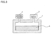
- a casting step using a pressureless permeation method which causes a molten metal to permeate the composite material is described below in detail with reference to FIGS. 2 and 3.
- FIGS. 2 and 3 are schematic configuration diagrams of a device for producing the composite metal material by using the pressureless permeation method.
- a composite material 4 which is further mixed with magnesium particles 44 as a reducing agent and compression-preformed in a forming die having the shape of the final product, may be used.
- the composite material 4 e.g. composite material using carbon nanofibers as first carbon material 40
- FIG. 2 An ingot of a matrix metal material formed of the same metal as the metal material Z, such as an aluminum ingot 5, is disposed on the composite material 4.
- the composite material 4 and the aluminum ingot 5 disposed in the container 1 are heated to a temperature equal to or higher than the melting point of aluminum by using heating means (not shown) provided in the container 1.
- the heated aluminum ingot 5 is melted to form molten aluminum (molten metal).
- the molten aluminum permeates the space in the composite material 4.
- the composite material 4 is formed to have a space which allows the molten aluminum to rapidly permeate the entire composite material 4 by a capillary phenomenon when compression-preforming the composite material 4. If the composite material 4 maintains a certain shape, the composite material 4 may not be compression-preformed.
- the atmosphere inside the container 1 may be replaced with a reducing atmosphere by mixing a small amount of magnesium particles 44 with the particulate composite material 4 before compression-preforming as in one embodiment of the invention.
- the molten aluminum permeates the space between the aluminum particles 42 reduced and provided with improved wettability due to the capillary phenomenon, whereby the composite material 4 is completely filled with the molten aluminum.
- the atmosphere inside the container 1 may be removed by decompression means 2 such as a vacuum pump connected with the container 1 before heating the container 1.
- Nitrogen gas may be introduced into the container 1 from inert-gas supply means 3 such as a nitrogen gas cylinder connected with the container 1.
- the composite material compression-preformed into a desired shape in advance is used.
- the permeation method may be performed by placing the composite material which is ground to particles in a die having a desired shape, and placing an ingot of another composite material on the composite material.
- the above-described embodiment illustrates the pressureless permeation method.
- a pressure permeation method which applies prcssurc by utilizing the pressure of an atmosphere such as an inert gas may also be used, for example.
- the surface of the carbon-based material has improved wettability with the matrix metal material (metal material Z). Since the surface of the carbon-based material has sufficient wettability with the molten matrix metal material (metal material Z), a homogenous composite metal material of which the variation in the mechanical properties is decreased over the entire material is obtained.
- Step 1 Open rolls with a roll diameter of six inches (roll temperature: 10 to 20°C) were provided with a predetermined amount (100 g) of a polymer substance (100 parts by weight (phr)) shown in Table 1, and the polymer substance was wound around the roll.
- Step 2 A substance including the element Y and a metal material Z were added to the polymer substance in amounts (parts by weight) shown in Table 1. The roll distance was set at 1.5 mm. The types of the substance including the element Y and the metal material Z added arc described later.
- Step 3 A first carbon material (''CNT" in Table 1) was added to the polymer substance containing the substance including the element Y and the metal material Z in an amount (parts by weight) shown in Table 1.
- the roll distance was set at 1.5 mm.
- Step 4 After the addition of the first carbon material, the mixture of the polymer substance and the first carbon material was removed from the rolls.
- Step 5 After reducing the roll distance from 1.5 nun to 0.3 mm, the mixture was supplied and tight milled. The surface velocity ratio of the two rolls was set at 1.1. The tight milling was repeatedly performed ten times.
- Step 6 After setting the rolls at a predetermined distance (1.1 mm), the mixture subjected to tight milling was supplied and sheeted.
- Examples 1 to 3 natural rubber (NR) with an average molecular weight of 3,000,000 was used.
- magnesium particles average particle diameter: 50 ⁇ m
- pure aluminum aluminum: 99.17%) particles
- carbon nanofibers (CNT) having a diameter (fiber diameter) of about 10 to 20 nm were used.
- the uncrosslinked sample (composite elastomer) obtained by (a) in each of Examples 1 to 3 was heat-treated for two hours in a heat treatment furnace having a nitrogen atmosphere containing a small amount of oxygen (substance including the clement X) at a temperature equal to or higher than the vaporization temperature of the elastomer and equal to or higher than ihe vaporization temperature (500°C) of the substance including the clement Y (magnesium) to vaporize and oxidize the elastomer to obtain an intermediate composite material containing a second carbon material and aluminum particles, and vaporize the substance including the element Y (magnesium) to obtain a composite material.
- a heat treatment furnace having a nitrogen atmosphere containing a small amount of oxygen (substance including the clement X) at a temperature equal to or higher than the vaporization temperature of the elastomer and equal to or higher than ihe vaporization temperature (500°C) of the substance including the clement Y (mag
- the oxidation reaction was canied out by utilizing oxygen molecules obtained from a small amount of oxygen and vapor contained in the nitrogen atmosphere inside the furnace and a small amount of oxygen and water contained in the elastomer.
- the vaporized substance including the element Y bonded to oxygen on the surface of the second carbon material.
- the composite material obtained by (b) in each of Examples 1 to 3 was dry-blended with magnesium particles.
- the resulting mixture was compression-formed to dimensions of 30 ⁇ 40 ⁇ 20 mm.
- the formed product and the aluminum ingot were disposed in a container (furnace) containing an inert gas (nitrogen) atmosphere and heated to 750°C.
- the magnesium particles vaporized and the aluminum ingot melted to become molten aluminum, and the molten metal permeated the space in the compression-formed composite material.
- the molten aluminum was allowed to cool and solidify to obtain a composite metal material.
- Comparative Example 1 a pure aluminum (aluminum: 99.17%) ingot was used.
- Comparative Example 2 a composite metal material, obtained by dry-blending carbon nanofibers (which were not surface-treated) having a diameter (fiber diameter) of about 10 to 20 nm with pure aluminum (aluminum: 99.17%) and sintering the mixture, was used.
- the magnesium particles mixed when preparing the composite metal material served as a reducing agent at the end of the molten aluminum.
- the carbon nanofiber content of the composite metal materials of Examples 1, 2, and 3 was respectively 0.4 vol%, 1.6 vol%, and 3.2 vol%.
- Table 1 shows XPS analysis results of the carbon-based materials in the composite materials obtained by (c) in Examples 1 to 3.
- the case where the presence of a carbon-oxygen bond was confirmed on the surface of the first carbon material in the carbon-based material is indicated as "surface oxidation”, and the case where the presence of a carbon-oxygen bond was not confirmed is indicated as "none”.
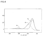
- FIG. 4 shows a schematic diagram of XPS data on the carbon-based material of Example 2.
- a second line segment 60 indicates a single bond "C-O”
- a third line segment 70 indicates a carbon-carbon bond.
- Table 1 shows XPS analysis results of the composite metal materials obtained by (d) in Examples 1 to 3.
- Mg the case where the presence of magnesium was confirmed around the carbon-based material
- FIGS. 5, 6, and 7 show EPS data on the carbon-based material of Example 2.
- FIGS. 5 to 7 show image data obtained by the EDS analysis. Since the presence or absence of elements is unclear in the black-and-white image, negative-positive inversion processing was performed.
- the black area in FIG. 5 indicates the presence of carbon, that is, the carbon nanofiber used as the first carbon material.
- the black area in FIG. 6 indicates the presence of oxygen.
- the black (dark) area in FIG. 7 indicates the presence of magnesium.
- a 10 ⁇ 10 mm sample with a thickness of 5 mm was prcparcd from each of the composite metal materials obtained by (c) in Examples J to 3 and Comparative Example 2 and aluminum of Comparative Example 1.
- the 0.2% yield strength (s 0.2) when compressing the sample at 0.01 mm/min was measured.
- the maximum value, minimum value, and mean value (MPa) of the compressive yield strength were determined. The results are shown in Table 1.
- the compressive yield strength of the composite metal materials of Examples 1 to 3 was greater than that of Comparative Examples 1 and 2.
- a significant increase in the compressive yield strength is confirmed by comparison between Example 2 and Comparative Example 2, in which the carbon nanofiber content of the matrix metal (aluminum) was 1.6 vol%.
- the variation in the compressive yield strength of the composite metal materials of Examples 1 to 3 was about ⁇ 10%. Therefore, it was found that a homogeneous composite material of which the variation in mechanical properties was reduced over the entire material was obtained.
- a composite metal material having uniform mechanical properties in which carbon nanofibers generally having poor dispersibility in a matrix are uniformly dispersed, can be obtained.
- a composite metal material having excellent mechanical properties can be obtained by an improvement of the wettability between the carbon-based material and aluminum as the matrix metal.
Landscapes
- Chemical & Material Sciences (AREA)
- Engineering & Computer Science (AREA)
- Materials Engineering (AREA)
- Mechanical Engineering (AREA)
- Metallurgy (AREA)
- Organic Chemistry (AREA)
- Crystallography & Structural Chemistry (AREA)
- Nanotechnology (AREA)
- Physics & Mathematics (AREA)
- Condensed Matter Physics & Semiconductors (AREA)
- General Physics & Mathematics (AREA)
- Composite Materials (AREA)
- Plasma & Fusion (AREA)
- Manufacture Of Alloys Or Alloy Compounds (AREA)
- Compositions Of Macromolecular Compounds (AREA)
- Powder Metallurgy (AREA)
- Processing And Handling Of Plastics And Other Materials For Molding In General (AREA)
Abstract
Description
- The present invention relates to a composite material and a method of producing the same, and a composite metal material and a method of producing the same.
- A composite material using a carbon material such as carbon fiber, carbon black, graphite, or carbon nanofiber has attracted attention (see JP-A-5-78110, for example). Such a composite material is expected to exhibit improved electric conductivity, heat transfer properties, and mechanical strength due to inclusion of the carbon material such as carbon nanofiber.
- However, the carbon material generally exhibits low wettability (affinity) with a matrix material of the composite material and exhibits low dispersibility in the matrix material. In particular, since the carbon nanofibers have strong aggregating properties, it is very difficult to uniformly disperse the carbon nanofibers in a matrix of the composite material. Therefore, it is difficult to obtain a carbon nanofiher composite material having desired properties. Moreover, expensive carbon nanofibers cannot be cfticicntly utilized.
- According to a first aspect of the invention, there is provided a method of producing a composite material which includes a carbon-based material and a particulate or fibrous metal material Z, the method comprising:
- (a) mixing at least a first carbon material and the metal material Z into an elastomer, and dispersing the first carbon material and the metal material Z by applying a shear force to obtain a composite elastomer, the metal material Z having a melting point lower than a melting point of the first carbon material;
- (b) heat-treating the composite clastomcr to vaporize the elastomer included in the composite elastomer to obtain an intermediate composite material including a second carbon material and the metal material Z; and
- (c) heat-treating the intermediate composite material together with a substance including an clement Y having a melting point lower than the melting point of the metal material Z to vaporize the substance including the element Y.
- According to a second aspect of the invention, there is provided a composite material obtained by the above-described method of producing a composite material.
- According to a third aspect of the invention, there is provided a composite material which includes a carbon-based material and a particulate or fibrous metal material Z, wherein:
- the carbon-based material has a first bonding structure and a second bonding structure on a surface of a carbon material;
- the first bonding structure is a structure in which an element X bonds to a carbon atom of the carbon material;
- the second bonding structure is a structure in which an element Y bonds to the element X;
- the element X includes at least one clement selected from boron, nitrogen, oxygen, and phosphorus;
- the element Y includes at least one element selected from magnesium, aluminum, silicon, calcium, titanium, vanadium, chromium, manganese, iron, nickel, copper, zinc, and zirconium; and
- the metal material Z is aluminum or magnesium.
- According to a fourth aspect of the invention, there is provided a method of producing a composite metal material, the method comprising:
- (d-1) powder forming the composite material obtained by the above-described method of producing a composite material.
- According to a fifth aspect of the invention, there is provided a method of producing a composite metal material, the method comprising:
- (d-2) casting the composite material obtained by the above-described method of producing a composite material.
- According to a sixth aspect of the invention, there is provided a method of producing a composite metal material, the method comprising:
- (d-3) causing a molten matrix metal material to permeate the composite material obtained by the above-described method of producing a composite material,
wherein a material for the matrix metal material is the same as a material for the metal material Z. - According to a seventh aspect of the invention, there is provided a composite metal material obtained by any of the above-described methods of producing a composite metal material.
-
- FIG. 1 schematically shows a mixing method for an elastomer and a carbon material utilizing an open-roll method used in one embodiment of the invention.
- FIG. 2 is a schematic configuration diagram of a device for producing a composite material by using a pressureless permeation method.
- FIG. 3 is a schematic configuration diagram of a device for producing a composite material by using a pressureless permeation method.
- FIG. 4 is a schematic diagram showing XPS data on a carbon-based material obtained in an example according to the invention.
- FIG. 5 shows EDS data (carbon) on a composite material obtained in an example according to the invention.
- FIG. 6 shows EDS data (oxygen) on a composite material obtained in an example according to the invention.
- FIG. 7 shows EDS data (magnesium) on a composite material obtained in an example according to the invention.
- The invention may provide a composite material including a carbon-based material exhibiting improved surface wettability, and a method of producing the same. The invention may also provide a composite metal material in which a carbon material is uniformly dispersed, and a method of producing the same.
- According to one embodiment of the invention, there is provided a method of producing a composite material which includes a carbon-based material and a particulate or fibrous metal material Z, the method comprising:
- (a) mixing at least a first carbon material and the metal material Z into an elastomer, and dispersing the first carbon material and the metal material Z by applying a shear force to obtain a composite elastomer, the metal material Z having a melting point lower than a melting point of the first carbon material;
- (b) heat-treating the composite elastomer to vaporize the elastomer included in the composite elastomer to obtain an intermediate composite material including a second carbon material and the metal material Z; and
- (c) heat-treating the intermediate corriposite material together with a substance including an element Y having a melting point lower than the melting point of the metal material Z to vaporize the substance including the element Y.
- According to the step (a) of the method according to one embodiment of the invention, free radicals formed in the elastomer shorn by the shear force attack the surface of the first carbon material, whereby the surface of the first carbon material is activated. Therefore, the dispersibility of the first carbon material in the elastomer is improved. When using carbon nanofibers as the first carbon material, since an unsaturated bond or group of the elastomer bonds to an active site of the carbon nanotiber, particularly to a terminal radical of the carbon nanofiber, the aggregating force of the carbon nanofibers is reduced, whereby the dispersibility of the carbon nanofiher can be increased.
- According to the step (b) of the method according to one embodiment of the invention, the second carbon material having an activated surface is obtained by vaporizing the elastomer by the heat treatment. According to the step (c) of the method according to one embodiment of the invention, the substance including the element Y is vaporized by the heat treatment so that the element Y adheres to the surface of the second carbon material, whereby the carbon-based material exhibiting improved wettability with the matrix material is obtained. Moreover, since the second carbon material is heat-treated together with the particulate or fibrous metal material Z, a composite material containing the metal material Z and the carbon-based material is obtained. Therefore, the composite material obtained by the method according to one embodiment of the invention can be easily utilized for general metalworking such as casting. A composite metal material having desired properties can be produced by adjusting the mixing ratio of the metal material Z to the carbon-based material. Moreover, since the metal material Z exists in the steps (b) and (C), reaggregation of the carbon material can be prevented.
- The elastomer according to one embodiment of the invention may be a rubber elastomcr or a thermoplastic elastomer. When using a rubber elastomer, the elastomer may be in a crosslinked form or an uncrosslinked form. As the raw material elastomer, an uncrosslinked form is used when using a rubber elastomer.
- In this method of producing a composite material, the step (a) in which the carbon material is dispersed into the elastomer by applying a shear force may be performed by using a method such as an open roll method with a roll interval of 0.5 mm or less, an internal mining method, or a multi-screw extrusion kneading method.
- According to one embodiment of the invention, there is provided a composite material which includes a carbon-based material and a particulate or fibrous metal material Z, wherein:
- the carbon-based material has a first bonding structure and a second bonding structure on a surface of a carbon material;
- the first bonding structure is a structure in which an element X bonds to a carbon atom of the carbon material;
- the second bonding structure is a structure in which an element Y bonds to the element X;
- the element X includes at least one element selected from boron, nitrogen, oxygen, and phosphorus;
- the element Y includes at least one element selected from magnesium, aluminum, silicon, calcium, titanium, vanadium, chromium, manganese, iron, nickel, copper, zinc, and zirconium; and
- the metal material Z is aluminum or magnesium.
- In this composite material, the first bonding structure may be a structure in which oxygen bonds to a carbon atom of the carbon material; and the second bonding structure may be a structure in which magnesium bonds to oxygen.
- According to one embodiment of the invention, there is provided a method of producing a composite metal material, the method comprising:
- (d-1) powder forming the composite material obtained by the above-described method of producing the composite material;
- (d-2) casting the composite material obtained; or
- (d-3) causing a molten matrix metal material to permeate the composite material.
- Since the element Y adheres to the surface of the carbon-based material of the composite material obtained according to one embodiment of the invention, the surface of the carbon-based material exhibits excellent wettability with the metal material Z as the matrix of the composite metal material. Moreover, a composite metal material in which the carbon-based material is uniformly dispersed in the metal material Z as the matrix can he obtained by the improvement of the wettability of the carbon-based material.
- These embodiments of the invention will be described in detail below, with reference to the drawings.
- The elastomer preferably has a molecuiar weight of 5,000 to 5,000,000, and more preferably 20,000 to 3,000,000. If the molecular weight of the elastomer is within this range, since the elastomer molecules are entangled and linked, the elastomer easily enters the space in the aggregated first carbon material (e.g. carbon nanofibers) to exhibit an improved effect of separating the carbon nanofibers. If the molecular weight of the elastomer is less than 5,000, since the elastomer molecules cannot be sufficiently entangled, the effect of dispersing the first carbon material is reduced even if a shear force is applied in the subsequent step. If the molecular weight of the elastomer is greater than 5,000,000, the elastomer becomes too hard so that processing becomes difficult.
- A network component of the elastomer in an uncrosslinkcd form preferably has a spin-spin relaxation time (T2n/30°C) of 100 to 3,000 µsec, and more preferably 200 to 1,000 µsec, measured at 30°C by a Hahn echo method using a pulsed nuclear magnetic resonance (NMR) technique. If the elastomer has a spin-spin relaxation time (T2n/30°C) within the above range, the elastomer is flexible and has a sufficiently high molecular mobility. Therefore, when mixing the elastomer and the first carbon material, the elastomer can easily enter the space in the first carbon material due to high molecular motion. If the spin-spin relaxation time (T2n/30°C) is shorter than 100 µsec, the elastomer cannot have a sufficient molecular mobility. If the spin-spin relaxation time (T2n/30°C) is longer than 3,000 µsec, since the elastomer tends to flow as a liquid, it becomes difficult to disperse the first carbon material.
- A network component of the elastomer in a crosslinked form preferably has a spin-spin relaxation time (T2n) of 100 to 2,000 µsec, measured at 30°C by a Hahn-echo method using a pulsed nuclear magnetic resonance (NMR) technique. The reasons therefor are the same as those described for the uncrosslinked form. Specifically, when crosslinking an uncrosslinked form which satisfies the above conditions by using the method according to the invention, the spin-spin relaxation time (T2n) of the resulting crosslinked form almost falls within the above range.
- The spin-spin relaxation time obtained by the Hahn-echo method using the pulsed NMR technique is a measure which indicates the molecular mobility of a substance. In more detail, when measuring the spin-spin relaxation time of the clastomer by the Hahn-echo method using the pulsed NMR technique, a first component having a shorter first spin-spin relaxation time (T2n) and a second component having a longer second spin-spin relaxation time (T2nn) arc detected. The first component corresponds to the network component (backbone molecule) of the polymer, and the second component corresponds to the non-network component (branched component such as terminal chain) of the polymer. The shorter the first spin-spin relaxation time, the lower the molecular mobility and the harder the elastomer. The longer the first spin-spin relaxation time, the higher the molecular mobility and the softer the elastomer.
- As the measurement method in the pulsed NMR technique, a solid-echo method, a Carr-Purcell-Meiboom-Gill (CPMG) method, or a 90-degree pulse method may be applied instead of the Hahn-echo method. However, since the elastomer according to the invention has a medium spin-spin relaxation time (T2), the Hahn-echo method is most suitable. In general, the solid-echo method and the 90-degree pulse method are suitable for measuring a short spin-spin relaxation time (T2), the Hahn-echo method is suitable for measuring a medium spin-spin relaxation time (T2), and the CPMG method is suitable for measuring a long spin-spin relaxation time (T2).
- At least one of the main chain, side chain, and terminal chain of the elastomer includes an unsaturated bond or a group having affinity to the first carbon material, particularly to a terminal radical of the carbon nanofiber, or the elastomer has properties of readily producing such a radical or group. The unsaturated bond or group may be at least one unsaturated bond or group selected from a double bond, a triple bond, and functional groups such as a-hydrogen, a carbonyl group, a carboxyl group, a hydroxyl group, an amino group, a nitrile group, a ketone group, an amide group, an epoxy group, an ester group, a vinyl group, a halogen group, a urethane group, a biuret group, an allophanate group, and a urea group.
- The carbon nanofiber generally has a structure in which the side surface is formed of a six-membered ring of carbon atoms and the end is closed by introduction of a five-membered ring. However, since the carbon nanofiber has a forced structure, a defect tends to occur, so that a radical or a functional group tends to be formed at the defect. In one embodiment of the invention, since at least one of the main chain, side chain, and terminal chain of the elastomer includes an unsaturated bond or a group having high affinity (reactivity or polarity) to the radical of the carbon nanofiber, the elastomer and the carbon nanofiber can be bonded. This enables the carbon nanofibers to be easily dispersed by overcoming the aggregating force of the carbon nanofibers. When mixing the elastomer and the first carbon material such as the carbon nanofibers, free radicals produced by breakage of the elastomer molecule attack the defects of the carbon nanofibers to produce free radicals on the surfaces of the carbon nanofibers.
- As the elastomer, an elastomer such as natural rubber (NR), epoxidized natural rubber (ENR), styrene-butadiene rubber (SBR), nitrile rubber (NBR), chloroprene rubber (CR), ethylene propylene rubber (EPR or EPDM), butyl rubber (IIR), chlorobutyl rubber (CIIR), acrylic rubber (ACM), silicone rubber (Q), fluorine rubber (FKM), butadiene rubber (BR), epoxidized butadiene rubber (EBR), epichlorohydrin rubber (CO or CEO), urethane rubber (U), or polysulfide rubber (T); a thermoplastic clastomer such as an olefin-based elastomer (TPO), poly(vinyl chloride)-based elastomer (TPVC), polyester-based elastomer (TPEE), polyurethane-based elastomer (TPU), polyamide-based elastomer (TPEA), or styrene-based elastomer (SBS); or a mixture of these elastomers may be used. In particular, a highly polar elastomer which readily produces free radicals during mixing of the elastomer, such as natural rubber (NR) or nitrile rubber (NBR), is preferable. An elastomer having a low polarity, such as ethylene propylene rubber (EPDM), may also be used in the invention, since such an elastomer also produces free radicals by setting the mixing temperature at a relatively high temperature (e.g. 50 to 150°C for EPDM).
- In the composite elastomer according to one embodiment of the invention, a crosslinked elastomer, an uncrosslinkcd elastomer, or a thennoplastic polymer may be directly used as the elastomer material.
- As the first carbon material, a carbon allotropc material may be used. For example, the first carbon material may be selected from carbon fiber, carbon black, amorphous carbon, graphite, diamond, fullerene, and the like. The carbon fiber used herein includes carbon nanofiber. When using carbon black, since the carbon black is inexpensive and commercially available in many grades, the carbon black can be relatively easily utilized. A nanomaterial such as a minute carbon material (e.g. carbon nanofiber or fullerene) achieves a high reinforcement effect with a small amount of addition.
- The amount of the first carbon material to be added may be determined depending on the type and the application of composite material or composite metal material.
- As the carbon black used in the invention, carbon black of various grades produced by using various raw materials may be used. The carbon black may be in a state of either elementary particles (primary particles) or an aggregate in which the elementary particles are fused and connected (agglomerate). However, carbon black having a comparatively high structure in which the aggregate is grown is preferable when used as a reinforcement filler.
- The carbon black used in the invention has an average elementary particle diameter of preferably 100 nm or less, and still more preferably 50 nm or less. The volume effect and the reinforcing effect are increased as the size of the carbon black particle becomes smaller. In practical application, the average particle diameter is preferably 10 to 30 nm.
- The size of the carbon black particle is also indicated by the nitrogen adsorption specific surface area. In this case, the nitrogen adsorption specific surface area is 10 m2/g or more, and preferably 40 m2/g or more as the nitrogen adsorption specific surface area (m2/g) measured according to JIS K 6217-2 (2001) "Carbon black for rubber industry - Fundamental characteristics - Part 2: Determination of specific surface area - Nitrogen adsorption methods - Single-point procedures".
- The reinforcing effect of the carbon black used in the invention is affected by the degree of structure of the aggregate in which the elementary particles arc fused. The reinforcing effect is increased by adjusting the DBP absorption to 50 cm3/100 g or more, and preferably 100 cm3/100 g or more. This is because the aggregate forms a higher structure as the DBP absorption is greater.
- As the carbon black used in the invention, carbon black of grades such as SAF-HS (N134, N121), SAF (N110, N115), JSAF-HS (N234), ISAF (N220, N220M), ISAF-LS (N219, N231), ISAF-HS (N285, N229), HAF-HS (N339, N347), HAF (N330), HAF-LS (N326), T-HS (N351, N299), T-NS (N330T), MAP (N550M), FEF (N550), GPF (N660, N630, N650, N683), SRF-HS-HM (N762, N774), SRF-LM (N760M, N754, N772, N762), FT, HCC, HCF, MCC, MCF, LEF, MFF, RCF, and RCC, and conductive carbon black such as Tokablack, HS-500, acetylene black, and Ketjenblaclc may be used.
- When the first carbon material is carbon fiber, particularly carbon nanofiber, the composite elastomer according to one embodiment of the invention preferably includes the carbon nanofibers in an amount of 0.01 to 50 wt%.
- The carbon nanofibers preferably have an average diameter of 0.5 to 500 nm. In order to increase the strength of the composite elastomer, the average diameter of the carbon nanofibers is still more preferably 0.5 to 30 nm. The carbon nanofiber may be either a linear fiber or a curved fiber.
- As examples of the carbon nanofiber, a carbon nanotube and the like can be given. The carbon nanotube has a single-layer structure in which a graphene sheet of a hexagonal carbon layer is closed in the shape of a cylinder, or a multi-layer structure in which the cylindrical structures are nested. Specifically, the carbon nanotube may be formed only of the single-layer structure or the multi-layer structure, or may have the single-layer structure and the multi-layer structure in combination. A carbon material having a partial carbon nanotube structure may also be used. The carbon nanotube may be called a graphite fibril nanotube.
- A single-layer carbon nanotube or a multi-layer carbon nanotube is produced to a desired size by using an arc diskharge method, a laser ablation method, a vapor-phase growth method, or the like.
- In the arc diskharge method, an arc is diskharged between electrode materials made of carbon rods in an argon or hydrogen atmosphere at a pressure slightly lower than atmospheric pressure to obtain a multi-layer carbon nanotube deposited on the cathode. When a catalyst such as nickel/cobalt is mixed into the carbon rod and an arc is diskharged, a single-layer carbon nanotube is obtained from soot adhering to the inner side surface of a processing vessel.
- In the laser ablation method, a target carbon surface into which a catalyst such as nickcl/cobalt is mixed is irradiated with strong pulse laser light from a YAG laser in a noble gas (e.g. argon) to melt and vaporize the carbon surface to obtain a single-layer carbon nanotube.
- In the vapor-phase growth method, a carbon nanotube is synthesized by thermally decomposing hydrocarbons such as benzene or toluene in a vapor phase. As specific examples of the vapor-phase growth method, a floating catalyst method, a zeolite-supported catalyst method, and the like can be given.
- The first carbon material may be provided with improved adhesion to and wettability with the elastomer by subjecting the carbon nanofibers to a surface treatment such as an ion-injection treatment, sputter-etching treatment, or plasma treatment before mixing the carbon nanofibers into the elastomer.
- The element Y bonds to the surface of the second carbon material to improve the wettability between the carbon-based material and the matrix metal material. A carbon material generally exhibits poor wettability with a metal material such as aluminum and magnesium. However, wettability is improved by using the carbon-based material having the element Y on the surface. A particulate substance including the element Y may be mixed and dispersed in the elastomer in advance in the step (a) so that the first carbon material is more favorably dispersed when mixing the first carbon material into the elastomer. In the step (a), the substance including the clement Y may be mixed into the elastomer before mixing the first carbon material, or may be mixed into the elastomer together with the first carbon material.
- The substance including the element Y preferably has an average particle diameter greater than the average diameter of the first carbon material used. The average particle diameter of the substance including the element Y is 500 µm or less, and preferably 1 to 300 µm. The shape of the substance including the element Y is not limited to spherical. The substance including the element Y may be in the shape of a sheet or scale insofar as turbulent flows occur around the substance including the element Y during mixing.
- The substance including the element Y preferably has a melting point lower than the melting point of the first carbon material and lower than the melting point of the metal material Z. If the melting point of the substance including the element Y satisfies the above condition, the substance including the element Y can be vaporized by the heat treatment in the step (c) without damaging the first carbon material and the metal material Z. When the metal material Z as the matrix metal contains aluminum or magnesium, the element Y preferably includes at least one element selected from magnesium, aluminum, silicon, calcium, titanium, vanadium, chromium, manganese, iron, nickel, copper, zinc, and zirconium. Therefore, the substance including the element Y may include at least one element Y selected from these elements. These clements are used as elements which form an aluminum alloy or a magnesium alloy. These elements easily bond to aluminum or magnesium, and can stably exist in a state in which the elements bond to aluminum or magnesium. As the element Y, magnesium, zinc, or aluminum, which exhibits particularly excellent bonding properties with magnesium or aluminum as the matrix metal material, may be used.
- In particular, when oxygen bonds to the surface of the first carbon material as the clement X, it is preferable to use magnesium as the element Y since magnesium easily bonds to oxygen. Therefore, the carbon-based material thus obtained has a first bonding structure and a second bonding structure on the surface of the carbon material, the first bonding structure being a structure in which the element X bonds to the carbon atom of the carbon material and the second bonding structure being a structure in which the element Y bonds to the element X. In particular, when the first bonding structure is a structure in which oxygen bonds to the carbon atom of the carbon material, it is preferable that the second bonding structure be a structure in which magnesium bonds to oxygen.
- The above description illustrates the case of mixing the substance including the element Y into the elastomer in the step (a). However, the invention is not limited thereto. It suffices that the substance including the element Y be subjected to the heat treatment in the step (c) together with the second carbon material. For example, the substance including the element Y may be disposed in a heat treatment furnace together with the second carbon material and vaporized by the heat treatment in the step (c). In this case, the substance including the element Y may not be particulate.
- In the invention, magnesium or aluminum used as the matrix material includes an alloy containing magnesium or aluminum as the major component.
- The metal material Z forms a composite material together with the carbon-based material, and prevents aggregation of the carbon-based material. The metal material Z may be used as a metal material as a matrix when producing a composite metal material.
- The metal material Z may be particulate or fibrous. When using a particulate metal material Z, the first carbon material can be more favorably dispersed in the elastomcr when mixing the first carbon material into the elastomer by mixing the metal material Z into the elastomer in the step (a). In the step (a), the metal material Z may be mixed into the elastomer before mixing the first carbon material, or may be mixed into the elastomer together with the first carbon material.
- A particulate metal material Z mixed into the elastomer in the step (a) preferably has an average particle diameter greater than the average diameter of the first carbon material used. The average particle diameter of the metal material Z is 500 µm or less, and preferably 1 to 300 µm. The shape of the metal material Z is not limited to spherical. The metal material Z may be in the shape of a sheet or a scale insofar as turbulent flows occur around the metal material Z during mixing.
- The metal material Z is preferably a metal having a melting point lower than the melting point of the first carbon material and higher than the melting point of the substance including the clement Y. The metal material Z is still more preferably a light metal having a melting point of 800°C or less and having an atomic weight of 100 or less. As examples of the metal material Z, magnesium, aluminum, and the like can be given. In the invention, magnesium or aluminum used as the metal material Z includes an alloy containing magnesium or aluminum as the major component.
- The step (a) may be performed by using a method such as an open roll method, an internal mixing method, or a multi-screw extrusion kneading method.
- In one embodiment of the invention, an example using an open-roll method with a roll distance of 0.5 mm or less is described below as the step of mixing the substance including the clement Y, the metal material Z, and the first carbon material into the elastomer.
- FIG. 1 is a diagram schematically showing the open-roll method using two rolls. In FIG. 1, a
reference numeral 10 indicates a first roll, and areference numeral 20 indicates a second roll. Thefirst roll 10 and thesecond roll 20 are disposed at a predetermined distance d of preferably 1.0 mm or less, and still more preferably 0-1 to 0.5 mm. The first and second rolls are rotated nonnally or reversely. In the example shown in FIG 1, thefirst roll 10 and thesecond roll 20 are rotated in the directions indicated by the arrows. When the surface velocity of thefirst roll 10 is indicated by V1 and the surface velocity of thesecond roll 20 is indicated by V2, the surface velocity ratio (V1/V2) of thefirst roll 10 to thesecond roll 20 is preferably 1.05 to 3.00, and still more preferably 1.05 to 1.2. A desired shear force can be obtained by using such a surface velocity ratio. When causing anelastomer 30 to be wound around thesecond roll 20 while rotating the first andsecond rolls bank 32 of the elastomer is formed between therolls bank 32, theelastomer 30, the substance including the element Y, and the metal material Z 42 are mixed by rotating the first andsecond rolls bank 32 in which theelastomer 30, the substance 41 including the element Y, and the metal material Z 42 are mixed, the first andsecond rolls second rolls second rolls elastomer 30, whereby the aggregated first carbon material is separated by the shear force so that portions of the first carbon material are removed one by one and become dispersed in theelastomer 30. When the substance 41 including the element Y and the metal material Z 42 are particulate, the shear force caused by the rolls causes turbulent flows to occur around the substance 41 including the element Y and the metal material Z 42 dispersed in the elastomer. These complicated flows cause the carbon material to be further dispersed in theclastomer 30. If theelastomer 30 and the first carbon material 40 are mixed before mixing the substance 41 including the element Y and the metal material Z 42, since the movement of theelastomer 30 is restrained by the first carbon material 40, it becomes difficult to mix the substance including the element Y. Therefore, it is preferable to mix the substance 41 including the element Y and the metal material Z 42 before adding the first carbon material 40 to theelastomer 30. - In the step (a), free radicals are produced in the elastomer shorn by the shear force and attack the surface of the first carbon material, whereby the surface of the first carbon material is activated. When using natural rubber (NR) as the elastomer, the natural rubber (NR) molecule is cut while being mixed by the rolls to have a molecular weight lower than the molecular weight, before being supplied to the open rolls. Since radicals are produced in the cut natural rubber (NR) molecule and attack the surface of the first carbon material during mixing, the surface of the first carbon material is activated.
- In the step (a), the elastomer and the first carbon material are mixed at a comparatively low temperature of preferably O to 50°C, and still more preferably 5 to 30°C in order to obtain as high a shear force as possible. When using the open-roll method, it is preferable to set the roll temperature at the above-mentioned temperature. The distance d between the first and
second rolls elastomer 30. - Since the clastomer according to one embodiment of the invention has the above-described characteristics, specifically, the above-described molecular configuration (molecular length), molecular motion, and chemical interaction with the first carbon material, dispersion of the first carbon material is facilitated. Therefore, a composite elastomer exhibiting excellent dispersibility and dispersion stability (first carbon material rarely reaggregates) can be obtained. In more detail, when mixing the elastomer and the first carbon material, the elastomer having an appropriately long molecular length and a high molecular mobility enters the space in the first carbon material, and a specific portion of the clastomer bonds to a highly active site of the first carbon material through chemical interaction. When a high shear force is applied to the mixture of the elastomer and the first carbon material in this state, the first carbon material moves accompanying the movement of the elastomer, whereby the aggregated first carbon material is separated and dispersed in the elastomer. The dispersed first carbon material is prevented from rcaggregating due to chemical interaction with the elastomer, whereby excellent dispersion stability can be obtained.
- Moreover, since predetermined amounts of the substance including the element Y and the metal material Z are included in the elastomer, a shear force is also applied in the direction in which the first carbon material is separated due to a number of complicated flows such as turbulent flows of the elastomer occurring around the substance including the element Y and the metal material Z. Therefore, even carbon nanofibers with a diameter of about 30 nm or less or carbon nanofibers in the shape of a curved fiber move in the flow direction of each clastomer molecule bonded to the carbon nanofibcrs due to chemical interaction, whereby the carbon nanofibers are uniformly dispersed in the elastomer.
- In the step of dispersing the first carbon material in the clastomer by applying a shear force, the above-mentioned internal mixing method or multi-screw extrusion kneading method may be used instead of the open-roll method. In other words, it suffices that this step apply a shear force to the elastomer sufficient to separate the aggregated first carbon material and produce radicals in the elastomer molecules.
- A composite elastomer obtained by the step of mixing and dispersing the substance including the element Y, the metal material Z, and the first carbon material in the elastomer (mixing and dispersing step) may be crosslinked by using a crosslinking agent and formed thereafter, or may be formed without crosslinking the composite elastomer. As the forming method, a compression forming process, an extrusion forming process, or the like may be used. The compression forming process includes forming the composite elastomer, in which the substance including the element Y, the metal material Z, and the first carbon material are dispersed, in a pressurized state for a predetermined time (e.g. 20 min) in a forming die having a desired shape and set at a predetermined temperature (e.g. 175°C).
- In the mixing and dispersing step of the elastomer and the first carbon material, or in the subsequent step, a compounding ingredient usually used in the processing of an elastomer such as rubber may be added. As the compounding ingredient, a known compounding ingredient may be used. As examples of the compounding ingredient, a crosslinking agent, vulcanizing agent, vulcanization accelerator, vulcanization retarder, softener, plasticizer, curing agent, reinforcing agent, filler, aging preventive, colorant, and the like can be given.
- In the composite elastomer according to one embodiment of the invention, the first carbon material is uniformly dispersed in the elastomer as a matrix. In other words, the elastomer is restrained by the first carbon material. The mobility of the elastomer molecules restrained by the first carbon material is small in comparison with the case where the elastomer molecules are not restrained by the first carbon material. Therefore, the first spin-spin relaxation time (T2n), the second spin-spin relaxation time (T2nn), and the spin-lattice relaxation time (T1) of the carbon fiber composite material according to one embodiment of the invention arc shorter than those of the elastomer which does not include the first carbon material. In particular, when mixing the first carbon material into the elastomer containing the substance including the element Y and the metal material Z, the second spin-spin relaxation time (T2nn) becomes shorter than that of the elastomer containing only the first carbon material. The spin-lattice relaxation time (T1) of the crosslinked form changes in proportion to the amount of the first carbon material mixed.
- In a state in which the elastomer molecules arc restrained by the first carbon material, the number of non-network components (non-reticulate chain components) is considered to be reduced for the following reasons. Specifically, when the molecular mobility of the elastomer is entirely decreased by the first carbon material, since the number of non-network components which cannot easily move is increased, the non-network components tend to behave in the same manner as the network components. Moreover, since the non-network components (terminal chains) easily move, the non-network components tend to be adsorbed on the active sites of the first carbon material. It is considered that these phenomena decrease the number of non-network components. Therefore, the fraction (fnn) of components having the second spin-spin relaxation time is smaller than that of an elastomer which does not contain the first carbon material. In particular, when mixing the first carbon material into the elastomer containing the substance including the element Y, the fraction (fnn) of components having the second spin-spin relaxation time is further reduced in comparison with an clastomer containing only the first carbon material.
- Therefore, the composite elastomer according to one embodiment of the invention preferably has values measured by the Hahn-echo method using the pulsed NMR technique within the following range.
- Specifically, it is preferable that, in the uncrosslinked form, the first spin-spin relaxation time (T2n) measured at 150°C be 100 to 3,000 µsec, the second spin-spin relaxation time (T2nn) measured at 150°C be absent or 1,000 to 10,000 µsec, and the fraction (fnn) of components having the second spin-spin relaxation time be less than 0.2.
- The spin-lattice relaxation time (T1) measured by the Hahn-echo method using the pulsed NMR technique is a measure which indicates the molecular mobility of a substance in the same manner as the spin-spin relaxation time (T2). In more detail, the shorter the spin-lattice relaxation time of the elastomer, the lower the molecular mobility and the harder the elastomer. The longer the spin-lattice relaxation time of the elastomer, the higher the molecular mobility and the softer the elastomer.
- The composite elastomer according to one embodiment of the invention preferably has a flow temperature, determined by temperature dependence measurement of dynamic viscoelasticity, 20°C or more higher than the flow temperature of the raw material elastomer. In the composite clastomcr according to one embodiment of the invention, the substance including the element Y, the metal material Z, and the first carbon material arc uniformly dispersed in the elastomer. In other words, the elastomer is restrained by the first carbon material as described above. In this state, the elastomer exhibits molecular motion smaller than that of an elastomer which does not include the first carbon material, whereby flowability is decreased. The composite elastomer according to one embodiment of the invention having such flow temperature characteristics shows a small temperature dependence of dynamic viscoelasticity to exhibit excellent thermal resistance.
- The intermediate composite material in which the second carbon material is dispersed around the metal material Z can be produced by the step (b) of heat-treating the composite elastomer to vaporize the elastomer included in the composite elastomer.
- The heat treatment conditions may be arbitrarily selected depending on the type of elastomer used. The heat treatment temperature is set at a point equal to or higher than the vaporization temperature of the elastomer and lower than the vaporization temperatures of the first carbon material and the metal material Z. When mixing the substance including the element Y in advance in the step (a), the heat treatment temperature is set at a point lower than the vaporization temperature of the substance including the element Y.
- The step (b) may be performed in the presence of the substance including the element X so that the second carbon material in which the element X bonds to the carbon atom of the first carbon material can be obtained. For example, the composite elastomer may include the substance including the element X, and the element X may be caused to bond to the carbon atom of the first carbon material by the heat treatment in the step (b). Or, the step (b) may be performed in an atmosphere containing the substance including the element X so that the element X is caused to bond to the carbon atom of the first carbon material, for example.
- The element X is an element which easily bonds to carbon via a covalent bond and is a light element with a valence of preferably two or more. For example, the element X may include at least one element selected from boron, nitrogen, oxygen, and phosphorus. The clement X is preferably oxygen. Since oxygen is present in air, oxygen can be easily used for the heat treatment of the step (b). Moreover, oxygen easily reacts with the activated first carbon material such as a radical of carbon nanofiber. Therefore, it is preferable to use oxygen as the element X. Moreover, since oxygen easily bonds to a metal material or a scmimctal material such as magnesium, the second carbon material to which oxygen bonds can easily bond to the element Y.
- When using oxygen as the element X, oxygen may be mixed into the atmosphere used for the heat treatment in the step (b). When using nitrogen as the element X, the step (b) may be carried out in an atmosphere containing ammonium gas as the substance including the element X. When using boron, phosphorus, or the like as the element X, the element or a compound of the element may be mixed into the elastomer before the step (b). In this case, the substance including the element X may be mixed during mixing in the step (a), for example.
- In the step (b) according to one embodiment of the invention, the composite elastomer obtained by the step (a) is disposed in a heat treatment furnace, and the atmosphere inside the furnace is heated to the vaporization temperature of the elastomer (e.g. 500°C). The elastomer is vaporized by heating and the surface of the first carbon material activated by the step (a) bonds to the element X contained in the atmosphere inside the fumace or included in the elastomer, whereby the surface-treated second carbon material is produced. Since the surface of the second carbon material has been activated by free radicals of the elastomer molecules shorn by the step (a), the surface of the carbon material can easily bond to oxygen present in the atmosphere inside the furnace, for example. Since the surface of the second carbon material thus obtained has been oxidized and activated, the second carbon material easily bonds to the element Y. In addition, since the surface of the second carbon material has been activated by the reaction with the radicals of the elastomer, the surface of the second carbon material easily bonds to the element Y even if the element X is not used.
- The composite material including the carbon-based material according to the invention and the metal material Z can be produced by the step (c) of heat-treating the intermediate composite material obtained by the step (b) together with the particulate or fibrous metal material Z having a melting point lower than the melting point of the first carbon material and the substance including the element Y having a melting point lower than the melting point of the metal material Z to vaporize the substance including the element Y.
- The heat treatment temperature in the step (c) is set at a point higher than the heat treatment temperature in the step (b), equal to or higher than the vaporization temperature of the substance including the element Y, and lower than the vaporization temperatures of the metal material Z and the first carbon material. The heat treatment in the step (c) may be performed at the same time as the step (b) by setting the heat treatment temperature in the step (b) at a point equal to or higher than the vaporization temperature of the substance including the element Y, or the step (b) may be performed in the process of increasing the temperature from room temperature to the heat treatment temperature in the step (c).
- When the second carbon material obtained by the step (b) and the substance including the element Y are heated to a temperature equal to or higher than the vaporization temperature of the substance including the clement Y in a heat treatment furnace, the substance including the clement Y is vaporized so that the element Y bonds to the surface of the second carbon material or the element Y bonds to the element X bonded to the surface of the second carbon material to obtain a carbon-based material according to the invention.
- The substance including the clement Y may be mixed into the composite elastomer in advance by mixing the substance including the element Y and the elastomer in the step (a) as stated above, or may not be mixed into the composite elastomer. When the substance including the element Y is not mixed into the composite elastomer in advance, the substance including the clement Y may be disposed in the heat treatment furnace in the step (c) together with the second carbon material, or may be vaporized and supplied to the heat treatment furnace. The substance including the element Y vaporized by the heat treatment bonds to the clement X bonded to the surface of the second carbon material. In the step (c), a desired carbon-based material can be obtained by disposing the second carbon material in the presence of the substance including the element Y which has been vaporized.
- When mixing the metal material Z into the elastomer in the step (a) as stated above, since the metal material Z is dispersed in the composite elastomer together with the first carbon material, the metal material Z and the carbon based material are uniformly dispersed in the composite material obtained by the heat-treatment in the steps (b) and (c). The composite material thus obtained prevents reaggregation of the carbon-based material due to the presence of the metal material Z.
- The vaporized substance including the element Y easily bonds to the element X present on the surface of the second carbon material so that a compound of the element X and the clement Y is produced. The element X prevents direct bonding between the clement Y and the first carbon material. For example, when the clement Y is aluminum, if the first carbon material directly bonds to aluminum, a substance which easily reacts with water, such as Al4C3, is produced. Therefore, it is preferable to perform the step (b) of causing the element X to bond to the surface of the first carbon material before the step (c) of vaporizing the substance including the element Y.
- In the carbon-based material thus obtained, the surface of the first carbon material (e.g. carbon nanofiher) has a structure in which the carbon atom of the carbon nanofiber bonds to the element X and the element X bonds to the element Y. Therefore, the carbon-based material has a structure in which the surface of the first carbon material (e.g. carbon nanofiber) is covered with the compound layer (e.g. oxide layer) of carbon and the element X and is also covered with the reaction product layer of the element X and the element Y (e.g. magnesium). The surface structure of the carbon-based material may be analyzed by X-ray photoelectron spectroscopy (XPS) or energy dispersive spectrum (EDS) analysis.
- In the step (d) according to one embodiment of the invention, (d-1) a step of powder forming the composite material, (d-2) a step of casting the composite material, or (d-3) a step of causing a molten matrix metal material to permeate the composite material may be employed.
- The powder forming step of the composite material according to one embodiment of the invention may be performed by powder forming the composite material obtained by the step (c). In more detail, the composite material obtained according to the above-described embodiment is compressed in a die either directly or after mixing with a matrix metal material formed of the same metal as the metal material Z, and sintered at the sintering temperature of the metal material Z (e.g. 550°C when the metal material Z is aluminum) to obtain a composite metal material.
- The powder forming according to one embodiment of the invention is the same as powder forming in a metal forming process and involves powder metallurgy. The powder forming according to one embodiment of the invention not only includes the case of using a powder raw material, but also includes the case of using a raw material formed in the shape of a block by compression-preforming the composite material. As the powder forming method, a general sintering method, a spark plasma sintering (SPS) method using a plasma sintering device, or the like may be employed.
- The composite material and the particles of the matrix metal material may be mixed by dry blending, wet blending, or the like. When using wet blending, it is preferable to mix (wet-blend) the matrix metal material with the powder of the composite material in a solvent. Therefore, since the composite material which is ground to powder such as particles or fibers can be used when dry blending or wet blending the composite material, the composite material is easily utilized for metalworking.
- The composite metal material produced by such powder forming is obtained in a state in which the carbon-based material is dispersed in the matrix metal material (metal material Z). In particular, since the metal material Z and the carbon-hased material have been uniformly dispersed in stage of the composite material, a homogenous composite metal material can be obtained by directly powder forming the composite material. When further adding a matrix metal material to the composite material, a composite metal material having desired properties can be produced by adjusting the mixing ratio of the composite material to the matrix metal material.
- The casting step of the composite material may be performed by casting the composite material obtained according to the above-described embodiment in a die having a desired shape either directly or after mixing the composite material into a molten matrix metal material (e.g. metal material Z). In the casting step, a metal mold casting method, a diccasting method, or a low-pressure casting method, in which a molten metal is poured into a die made of steel, may be employed. A method classified into a special casting method, such as a high-pressure casting method in which a molten metal is caused to solidify at a high pressure, a thixocasting method in which a molten metal is stirred, or a centrifugal casting method in which a molten metal is cast into a die by utilizing centrifugal force, may also be employed. In these casting methods, the molten matrix metal material is caused to solidify in a die in a state in which the carbon-based material is mixed into the molten matrix metal material to form a composite metal material.
- If the molten matrix metal material used in the casting step is the same metal as the metal material Z, the wettability with the metal material Z is improved, whereby the strength of the composite metal material as the product can be increased.
- In one embodiment of the invention, a casting step using a pressureless permeation method which causes a molten metal to permeate the composite material is described below in detail with reference to FIGS. 2 and 3.
- FIGS. 2 and 3 are schematic configuration diagrams of a device for producing the composite metal material by using the pressureless permeation method. As the metal material obtained according to the above-described embodiment, a
composite material 4, which is further mixed with magnesium particles 44 as a reducing agent and compression-preformed in a forming die having the shape of the final product, may be used. In FIG. 2, the composite material 4 (e.g. composite material using carbon nanofibers as first carbon material 40) formed in advance is placed in a sealedcontainer 1. An ingot of a matrix metal material formed of the same metal as the metal material Z, such as analuminum ingot 5, is disposed on thecomposite material 4. Thecomposite material 4 and thealuminum ingot 5 disposed in thecontainer 1 are heated to a temperature equal to or higher than the melting point of aluminum by using heating means (not shown) provided in thecontainer 1. Theheated aluminum ingot 5 is melted to form molten aluminum (molten metal). The molten aluminum permeates the space in thecomposite material 4. - The
composite material 4 according to one embodiment of the invention is formed to have a space which allows the molten aluminum to rapidly permeate the entirecomposite material 4 by a capillary phenomenon when compression-preforming thecomposite material 4. If thecomposite material 4 maintains a certain shape, thecomposite material 4 may not be compression-preformed. The atmosphere inside thecontainer 1 may be replaced with a reducing atmosphere by mixing a small amount of magnesium particles 44 with the particulatecomposite material 4 before compression-preforming as in one embodiment of the invention. The molten aluminum permeates the space between the aluminum particles 42 reduced and provided with improved wettability due to the capillary phenomenon, whereby thecomposite material 4 is completely filled with the molten aluminum. Then, heating using the heating means of thecontainer 1 is terminated so that the molten metal which has permeated thecomposite material 4 is allowed to cool and solidify to obtain acomposite metal material 6, as shown in F1G- 3, in which the carbon-based material is uniformly dispersed. Since the material for the metal material Z of thecomposite material 4 is the same as the material for the molten metal as the matrix to ensure easy bonding, the resulting composite metal material is homogeneous over the entire composite metal material. - The atmosphere inside the
container 1 may be removed by decompression means 2 such as a vacuum pump connected with thecontainer 1 before heating thecontainer 1. Nitrogen gas may be introduced into thecontainer 1 from inert-gas supply means 3 such as a nitrogen gas cylinder connected with thecontainer 1. - In one embodiment of the invention, the composite material compression-preformed into a desired shape in advance is used. However, the permeation method may be performed by placing the composite material which is ground to particles in a die having a desired shape, and placing an ingot of another composite material on the composite material.
- The above-described embodiment illustrates the pressureless permeation method. However, a pressure permeation method which applies prcssurc by utilizing the pressure of an atmosphere such as an inert gas may also be used, for example.
- As described above, since the element Y bonds to the surface of the carbon-based material in the composite material, the surface of the carbon-based material has improved wettability with the matrix metal material (metal material Z). Since the surface of the carbon-based material has sufficient wettability with the molten matrix metal material (metal material Z), a homogenous composite metal material of which the variation in the mechanical properties is decreased over the entire material is obtained.
- Examples according to the invention are described below. However, the invention is not limited to the following examples.
- Step 1: Open rolls with a roll diameter of six inches (roll temperature: 10 to 20°C) were provided with a predetermined amount (100 g) of a polymer substance (100 parts by weight (phr)) shown in Table 1, and the polymer substance was wound around the roll.
- Step 2: A substance including the element Y and a metal material Z were added to the polymer substance in amounts (parts by weight) shown in Table 1. The roll distance was set at 1.5 mm. The types of the substance including the element Y and the metal material Z added arc described later.
- Step 3: A first carbon material (''CNT" in Table 1) was added to the polymer substance containing the substance including the element Y and the metal material Z in an amount (parts by weight) shown in Table 1. The roll distance was set at 1.5 mm.
- Step 4: After the addition of the first carbon material, the mixture of the polymer substance and the first carbon material was removed from the rolls.
- Step 5: After reducing the roll distance from 1.5 nun to 0.3 mm, the mixture was supplied and tight milled. The surface velocity ratio of the two rolls was set at 1.1. The tight milling was repeatedly performed ten times.
- Step 6: After setting the rolls at a predetermined distance (1.1 mm), the mixture subjected to tight milling was supplied and sheeted.
- Uncrosslinked samples of composite elastomers of Examples 1 to 3 were thus obtained.
- As the polymer substance in Examples 1 to 3, natural rubber (NR) with an average molecular weight of 3,000,000 was used. In Examples 1 to 3, magnesium particles (average particle diameter: 50 µm) were used as the substance including the element Y, and pure aluminum (aluminum: 99.17%) particles (average particle diameter: 50 µm) were used as the metal material Z. As the first carbon material in Examples 1 to 3 and the carbon material in Comparative Example 2, carbon nanofibers (CNT) having a diameter (fiber diameter) of about 10 to 20 nm were used.
- The uncrosslinked sample (composite elastomer) obtained by (a) in each of Examples 1 to 3 was heat-treated for two hours in a heat treatment furnace having a nitrogen atmosphere containing a small amount of oxygen (substance including the clement X) at a temperature equal to or higher than the vaporization temperature of the elastomer and equal to or higher than ihe vaporization temperature (500°C) of the substance including the clement Y (magnesium) to vaporize and oxidize the elastomer to obtain an intermediate composite material containing a second carbon material and aluminum particles, and vaporize the substance including the element Y (magnesium) to obtain a composite material. The oxidation reaction was canied out by utilizing oxygen molecules obtained from a small amount of oxygen and vapor contained in the nitrogen atmosphere inside the furnace and a small amount of oxygen and water contained in the elastomer. The vaporized substance including the element Y bonded to oxygen on the surface of the second carbon material.
- The composite material obtained by (b) in each of Examples 1 to 3 was dry-blended with magnesium particles. The resulting mixture was compression-formed to dimensions of 30×40×20 mm. After placing an aluminum ingot (metal) on the formed product, the formed product and the aluminum ingot were disposed in a container (furnace) containing an inert gas (nitrogen) atmosphere and heated to 750°C. The magnesium particles vaporized and the aluminum ingot melted to become molten aluminum, and the molten metal permeated the space in the compression-formed composite material. After completion of permeation of the molten aluminum, the molten aluminum was allowed to cool and solidify to obtain a composite metal material.
- As Comparative Example 1, a pure aluminum (aluminum: 99.17%) ingot was used. As Comparative Example 2, a composite metal material, obtained by dry-blending carbon nanofibers (which were not surface-treated) having a diameter (fiber diameter) of about 10 to 20 nm with pure aluminum (aluminum: 99.17%) and sintering the mixture, was used. The magnesium particles mixed when preparing the composite metal material served as a reducing agent at the end of the molten aluminum.
- The carbon nanofiber content of the composite metal materials of Examples 1, 2, and 3 was respectively 0.4 vol%, 1.6 vol%, and 3.2 vol%.
- Table 1 shows XPS analysis results of the carbon-based materials in the composite materials obtained by (c) in Examples 1 to 3. In Table 1, the case where the presence of a carbon-oxygen bond was confirmed on the surface of the first carbon material in the carbon-based material is indicated as "surface oxidation", and the case where the presence of a carbon-oxygen bond was not confirmed is indicated as "none". FIG. 4 shows a schematic diagram of XPS data on the carbon-based material of Example 2. A
first line segment 50 indicates a double bond "C=O", asecond line segment 60 indicates a single bond "C-O", and athird line segment 70 indicates a carbon-carbon bond. - Table 1 shows XPS analysis results of the composite metal materials obtained by (d) in Examples 1 to 3. In Table 1, the case where the presence of magnesium was confirmed around the carbon-based material is indicated as "Mg", and the case where the presence of magnesium was not confirmed is indicated as "none". FIGS. 5, 6, and 7 show EPS data on the carbon-based material of Example 2. FIGS. 5 to 7 show image data obtained by the EDS analysis. Since the presence or absence of elements is unclear in the black-and-white image, negative-positive inversion processing was performed. The black area in FIG. 5 indicates the presence of carbon, that is, the carbon nanofiber used as the first carbon material. The black area in FIG. 6 indicates the presence of oxygen. The black (dark) area in FIG. 7 indicates the presence of magnesium.
- A 10×10 mm sample with a thickness of 5 mm was prcparcd from each of the composite metal materials obtained by (c) in Examples J to 3 and Comparative Example 2 and aluminum of Comparative Example 1. The 0.2% yield strength (s 0.2) when compressing the sample at 0.01 mm/min was measured. The maximum value, minimum value, and mean value (MPa) of the compressive yield strength were determined. The results are shown in Table 1.

- From the results shown in Table 1, the following items were confirmed by Examples 1 to 3 according to the invention.
- From the XPS analysis results of the carbon-based materials of Examples 1 to 3, it was found that the carbon-based material had a structure in which the surface of the carbon-based material was oxidized and oxygen bonded to the carbon atom of the carbon nanofiber.
- The compressive yield strength of the composite metal materials of Examples 1 to 3 was greater than that of Comparative Examples 1 and 2. In particular, a significant increase in the compressive yield strength is confirmed by comparison between Example 2 and Comparative Example 2, in which the carbon nanofiber content of the matrix metal (aluminum) was 1.6 vol%. While the variation in the compressive yield strength of the composite metal material of Comparative Example 2 was about =30%, the variation in the compressive yield strength of the composite metal materials of Examples 1 to 3 was about ±10%. Therefore, it was found that a homogeneous composite material of which the variation in mechanical properties was reduced over the entire material was obtained. As a result of scanning electron microscopic observation of the composite metal materials of Examples 1 to 3 and Comparative Example 2, it was found that the dispersibility of the carbon nanofibers in the composite metal materials of Examples 1 to 3 was good, and that the carbon nanotibers were not sufficiently dispersed in the composite metal material Comparative Example 2 since many aggregates were observed.
- According to the invention, it was found that a composite metal material having uniform mechanical properties, in which carbon nanofibers generally having poor dispersibility in a matrix are uniformly dispersed, can be obtained. According to the invention, it was also found that a composite metal material having excellent mechanical properties can be obtained by an improvement of the wettability between the carbon-based material and aluminum as the matrix metal.
- Although only some embodiments of the invention have been described in detail above, those skilled in the art will readily appreciate that many modifications are possible in the embodiments without departing from the novel teachings and advantages of this invention. Accordingly, all such modifications arc intended to be included within the scope of this invention.
Claims (30)
- A method of producing a composite material which includes a carbon-based material and a particulate or fibrous metal material Z, the method comprising:(a) mixing at least a first carbon material and the metal material Z into an elastomer, and dispersing the first carbon material and the metal material Z by applying a shear force to obtain a composite elastomer, the metal material Z having a melting point lower than a melting point of the first carbon material;(b) heat-treating the composite elastomer to vaporize the elastomer included in the composite elastomer to obtain an intermediate composite material including a second carbon material and the metal material Z; and(c) heat-treating the intermediate composite material together with a substance including an element Y having a melting point lower than the melting point of the metal material Z to vaporize the substance including the element Y.
- The method of producing a composite material as defined in claim 1,
wherein the step (b) is performed in the presence of a substance including an element X so that the element X bonds to a carbon atom of the first carbon material; and
wherein the element X includes at least one element selected from boron, nitrogen, oxygen, and phosphorus. - The method of producing a composite material as defined in claim 2,
wherein the composite elastomer includes the substance having the element X; and
wherein the element X bonds to a carbon atom of the first carbon material by the heat treatment in the step (b). - The method of producing a composite material as defined in claim 2,
wherein the step (b) is performed in an atmosphere containing the substance having the element X so that the element X bonds to a carbon atom of the first carbon material. - The method of producing a composite material as defined in any of claims 2 to 4,
wherein the element X is oxygen or nitrogen. - The method of producing a composite material as defined in any of claims 1 to 5,
wherein the substance including the element Y is mixed with the elastomer in the step (a). - The method of producing a composite material as defined in any of claims 1 to 5,
wherein, in the step (c), the substance including the element Y is disposed in a heat treatment furnace together with the second carbon material and vaporized by the heat treatment. - The method of producing a composite material as defined in any of claims 1 to 7,
wherein the metal material Z is aluminum; and
wherein the element Y includes at least one element selected from magnesium, aluminum, silicon, calcium, titanium, vanadium, chromium, manganese, iron, nickel, copper, zinc, and zirconium. - The method of producing a composite material as defined in any of claims 1 to 7,
wherein the metal material Z is magnesium; and
wherein the element Y includes at least one element selected from magnesium, aluminum, silicon, calcium, titanium, vanadium, chromium, manganese, iron, nickel, copper, zinc, and zirconium. - The method of producing a composite material as defined in any of claims 1 to 9,
wherein the first carbon material is carbon black. - The method of producing a composite material as defined in any of claims 1 to 9,
wherein the first carbon material is carbon fiber. - The method of producing a composite material as defined in claim 11,
wherein the carbon fiber is carbon nanofiber. - The method of producing a composite material as defined in claim 12,
wherein the carbon nanofibers have an average diameter of 0.5 to 500 nm. - The method of producing a composite material as defined in any of claims .1 to 13,
wherein the elastomer has a molecular weight of 5,000 to 5,000,000. - The method of producing a composite material as defined in any of claims 1 to 14,
wherein at least one of a main chain, a side chain, and a terminal chain of the elastomer includes at least one unsaturated bond or group having affinity to carbon nanofibers and selected from a double bond, a triple bond, and functional groups such as a-hydrogen, a carbonyl group, a carboxyl group, a hydroxyl group, an amino group, a nitrile group, a ketone group, an amide group, an epoxy group, an ester group, a vinyl group, a halogen group, a urethane group, a biuret group, an allophanate group, and a urea group. - The method of producing a composite material as defined in any of claims 1 to 15,
wherein a network component of the elastomer in an uncrosslinked form has a spin-spin relaxation time (T2n) of 100 to 3,000 µsec, measured at 30°C by a Hahn-echo method using a pulsed nuclear magnetic resonance (NMR) technique. - The method of producing a composite material as defined in any of claims 1 to 16,
wherein a network component of the elastomer in a crosslinked form has a spin-spin relaxation time (T2n) of 100 to 2,000 µsec, measured at 30°C by a Hahn-echo method using a pulsed nuclear magnetic resonance (NMR) technique. - The method of producing a composite material as defined in any of claims 1 to 17,
wherein the elastomer is natural rubber or nitrile butadiene rubber. - The method of producing a composite material as defined in any of claims 1 to 18,
wherein the step (a) is performed by using an open roll method with a roll interval of 0.5 mm or less. - The method of producing a composite material as defined in claim 19,
wherein two rolls used in the open-roll method have a surface velocity ratio of 1.05 to 3.00. - The method of producing a composite material as defined in any of claims 1 to 18,
wherein the step (a) is performed by using an internal mixing method. - The method of producing a composite material as defined in any of claims 1 to 18,
wherein the step (a) is performed by using a multi-screw extrusion kneading method. - The method of producing a composite material as defined in any of claims 1 to 22,
wherein the step (a) is performed at 0 to 50°C. - A composite material obtained by the method as defined in any of claims 1 to 23.
- A composite material which includes a carbon-based material and a particulate or fibrous metal material Z, wherein:the carbon-based material has a first bonding structure and a second bonding structure on a surface of a carbon material;the first bonding structure is a structure in which an clement X bonds to a carbon atom of the carbon material;the second bonding structure is a structure in which an element Y bonds to the element X;the element X includes at least one element selected from boron, nitrogen, oxygen, and phosphorus;the element Y includes at least one element selected from magnesium, aluminum, silicon, calcium, titanium, vanadium, chromium, manganese, iron, nickel, copper, zinc, and zirconium; andthe metal material Z is aluminum or magnesium.
- The composite material as defined in claim 25,
wherein the first bonding structure is a structure in which oxygen bonds to a carbon atom of the carbon material; and
wherein the second bonding structure is a structure in which magnesium bonds to oxygen. - A method of producing a composite metal material, the method comprising:(d-1) powder forming the composite material obtained by the method as defined in any of claims 1 to 23.
- A method of producing a composite metal material, the method comprising:(d-2) casting the composite material obtained by the method as defined in any of claims 1 to 23.
- A method of producing a composite metal material, the method comprising:(d-3) causing a molten matrix metal material to permeate the composite material obtained by the method as defined in any of claims 1 to 23,wherein a material for the matrix metal material is the same as a material for the metal material Z.
- A composite metal material obtained by the method as defined in any of claims 27 to 29.
Applications Claiming Priority (1)
| Application Number | Priority Date | Filing Date | Title |
|---|---|---|---|
| JP2004262391A JP4279220B2 (en) | 2004-09-09 | 2004-09-09 | Composite material and manufacturing method thereof, composite metal material and manufacturing method thereof |
Publications (2)
| Publication Number | Publication Date |
|---|---|
| EP1637255A1 true EP1637255A1 (en) | 2006-03-22 |
| EP1637255B1 EP1637255B1 (en) | 2011-01-19 |
Family
ID=35539541
Family Applications (1)
| Application Number | Title | Priority Date | Filing Date |
|---|---|---|---|
| EP05255523A Expired - Lifetime EP1637255B1 (en) | 2004-09-09 | 2005-09-08 | Composite metal material and method of producing the same |
Country Status (6)
| Country | Link |
|---|---|
| US (2) | US7803297B2 (en) |
| EP (1) | EP1637255B1 (en) |
| JP (1) | JP4279220B2 (en) |
| KR (1) | KR100675069B1 (en) |
| CN (1) | CN100443620C (en) |
| DE (1) | DE602005025969D1 (en) |
Cited By (1)
| Publication number | Priority date | Publication date | Assignee | Title |
|---|---|---|---|---|
| WO2009141100A1 (en) * | 2008-05-23 | 2009-11-26 | Alcan Technology & Management Ltd. | Method for producing a component from a composite material |
Families Citing this family (14)
| Publication number | Priority date | Publication date | Assignee | Title |
|---|---|---|---|---|
| JP4224428B2 (en) * | 2004-05-24 | 2009-02-12 | 日信工業株式会社 | Method for producing metal material, method for producing carbon fiber composite metal material |
| US8052918B2 (en) | 2004-07-21 | 2011-11-08 | Nissin Kogyo Co., Ltd. | Carbon-based material and method of producing the same, and composite material and method of producing the same |
| JP4279220B2 (en) * | 2004-09-09 | 2009-06-17 | 日信工業株式会社 | Composite material and manufacturing method thereof, composite metal material and manufacturing method thereof |
| JP2007039638A (en) * | 2005-03-23 | 2007-02-15 | Nissin Kogyo Co Ltd | Carbon fiber composite material |
| JP4224499B2 (en) | 2005-06-30 | 2009-02-12 | 日信工業株式会社 | Manufacturing method of fiber composite material |
| JP2007039649A (en) * | 2005-06-30 | 2007-02-15 | Nissin Kogyo Co Ltd | Composite material |
| WO2008032956A1 (en) * | 2006-09-11 | 2008-03-20 | C & Tech Co., Ltd. | Composite sintering materials using carbon nanotube and manufacturing method thereof |
| KR100839613B1 (en) | 2006-09-11 | 2008-06-19 | 주식회사 씨앤테크 | Composite sintered material using carbon nanotubes and its manufacturing method |
| JP5314803B1 (en) * | 2011-11-21 | 2013-10-16 | 積水化学工業株式会社 | Method for producing carbonaceous material-polymer composite material and carbonaceous material-polymer composite material |
| WO2014183024A1 (en) | 2013-05-09 | 2014-11-13 | University Of Houston | Solution based polymer nanofiller-composites synthesis |
| US20150141517A1 (en) * | 2013-11-15 | 2015-05-21 | Shin-Etsu Chemical Co., Ltd. | Granulated composite, rapid release tablet and method for producing same |
| CN103697162A (en) * | 2013-12-02 | 2014-04-02 | 哈尔滨理工大学 | Silver thin film composited carbon sealing ring and preparation method thereof |
| CN104589496B (en) * | 2015-01-30 | 2017-07-21 | 绍兴华晶科技有限公司 | A kind of kneading device of nano-zirconia powder |
| CN116790922A (en) * | 2023-06-27 | 2023-09-22 | 江苏大学 | Preparation method and device of biphase nano particles and rare earth reinforced aluminum alloy |
Citations (2)
| Publication number | Priority date | Publication date | Assignee | Title |
|---|---|---|---|---|
| JPH0578110A (en) | 1991-09-20 | 1993-03-30 | Nobuatsu Watanabe | Method for modifying surface of carbonaceous powder and granule |
| EP1600231A1 (en) * | 2004-05-24 | 2005-11-30 | Nissin Kogyo Co., Ltd | Metal material and method of producing the same, and carbon fiber-metal composite material and method of producing the same |
Family Cites Families (45)
| Publication number | Priority date | Publication date | Assignee | Title |
|---|---|---|---|---|
| US3297667A (en) * | 1963-02-28 | 1967-01-10 | Union Carbide Corp | Production of cis-1, 4-polydienes by polymerization of 1, 3-dienes |
| US3482963A (en) * | 1966-10-17 | 1969-12-09 | Dow Chemical Co | Method for production of particulate metal |
| JPS511728B1 (en) * | 1969-04-22 | 1976-01-20 | ||
| US3828839A (en) * | 1973-04-11 | 1974-08-13 | Du Pont | Process for preparing fiber reinforced metal composite structures |
| US4351484A (en) * | 1977-10-11 | 1982-09-28 | Hart Robert J | Method of grinding magnesium ingots and such ingots |
| JPS57188464A (en) | 1981-05-11 | 1982-11-19 | Mitsubishi Pencil Co | Carbon spring and manufacture |
| JPS5950149A (en) * | 1982-09-14 | 1984-03-23 | Toyota Motor Corp | Fiber-reinforced metallic composite material |
| US4902457A (en) * | 1986-04-07 | 1990-02-20 | Matsushita Electric Industrial Co., Ltd. | Method for manufacturing a porous material or a composite sintered product comprising zirconium oxide and a carbide |
| US5108964A (en) * | 1989-02-15 | 1992-04-28 | Technical Ceramics Laboratories, Inc. | Shaped bodies containing short inorganic fibers or whiskers and methods of forming such bodies |
| AU5336190A (en) | 1989-03-03 | 1990-09-26 | Hyperion Catalysis International | Applications for graphite fibrils |
| US5445327A (en) * | 1989-07-27 | 1995-08-29 | Hyperion Catalysis International, Inc. | Process for preparing composite structures |
| JPH03232937A (en) * | 1990-02-06 | 1991-10-16 | King Inbesuto Kk | Manufacture of metallic body by injection molding |
| US5372775A (en) * | 1991-08-22 | 1994-12-13 | Sumitomo Electric Industries, Ltd. | Method of preparing particle composite alloy having an aluminum matrix |
| US6184177B1 (en) * | 1992-02-28 | 2001-02-06 | Mhb Filtration Gmbh And Co. Kg | Method of producing activated carbon particles from spent granular organic ion-exchange resin |
| US5348592A (en) * | 1993-02-01 | 1994-09-20 | Air Products And Chemicals, Inc. | Method of producing nitrogen-hydrogen atmospheres for metals processing |
| JP3480535B2 (en) | 1994-09-05 | 2003-12-22 | 日機装株式会社 | Antistatic rubber composition |
| US5669434A (en) * | 1994-10-26 | 1997-09-23 | Honda Giken Kogyo Kabushiki Kaisha | Method and apparatus for forming an aluminum alloy composite material |
| US5573607A (en) * | 1995-05-06 | 1996-11-12 | Millennium Materials, Inc. | Metal matrix composites of aluminum, magnesium and titanium using silicon borides |
| JP3823371B2 (en) * | 1996-06-05 | 2006-09-20 | ダイキン工業株式会社 | Carbon fluoride composition, paint and image forming member, composite material and production method |
| US5843567A (en) * | 1997-06-03 | 1998-12-01 | Xerox Corporation | Electrical component containing magnetic particles |
| JP4812144B2 (en) * | 1998-07-22 | 2011-11-09 | 住友電気工業株式会社 | Aluminum nitride sintered body and manufacturing method thereof |
| US6193915B1 (en) * | 1999-09-03 | 2001-02-27 | Her Majesty The Queen In Right Of Canada, As Represented By The Minister Of Natural Resources | Process for fabricating low volume fraction metal matrix preforms |
| JP2001114903A (en) | 1999-10-21 | 2001-04-24 | Mitsuboshi Belting Ltd | Method for manufacturing rubber composition with dispersed carbon black |
| JP2002071595A (en) | 2000-08-30 | 2002-03-08 | Mitsuboshi Belting Ltd | Method for evaluating degree of crosslinking of rubber |
| US7094285B2 (en) * | 2000-09-20 | 2006-08-22 | Goodrich Corporation | Inorganic matrix compositions, composites incorporating the matrix, and process of making the same |
| US6538166B1 (en) * | 2001-05-18 | 2003-03-25 | A. Latif Mahjoob | Waste rubber treatment process and apparatus therefor |
| JP2003012863A (en) | 2001-06-27 | 2003-01-15 | Yokohama Rubber Co Ltd:The | Rubber composition |
| US20030125474A1 (en) * | 2001-06-27 | 2003-07-03 | Fumito Yatsuyanagi | Rubber composition |
| JP2003155384A (en) | 2001-11-21 | 2003-05-27 | Toyo Tire & Rubber Co Ltd | Rubber composition for tire tread |
| CN1394979A (en) * | 2002-06-28 | 2003-02-05 | 太原理工大学 | Aluminium base mixed continuous carbon fibre composite material and its preparation |
| JP2004068085A (en) * | 2002-08-07 | 2004-03-04 | Suzuki Motor Corp | Manufacturing method of aluminum composite |
| JP4096241B2 (en) * | 2002-10-24 | 2008-06-04 | 住友ゴム工業株式会社 | Rubber roller using elastomer composition |
| CN100373503C (en) | 2002-12-26 | 2008-03-05 | 昭和电工株式会社 | Carbonaceous materials for forming conductive materials and applications thereof |
| JP4005048B2 (en) | 2003-04-09 | 2007-11-07 | 日信工業株式会社 | Carbon fiber composite material and method for producing the same |
| JP4005058B2 (en) | 2003-07-23 | 2007-11-07 | 日信工業株式会社 | Carbon fiber composite material and method for producing the same, carbon fiber composite molded article and method for producing the same |
| JP2005078110A (en) | 2003-08-29 | 2005-03-24 | Toshiba Corp | Image detection method and image detection apparatus |
| JP4224407B2 (en) | 2004-01-29 | 2009-02-12 | 日信工業株式会社 | Method for producing composite metal material |
| JP4224445B2 (en) | 2004-02-06 | 2009-02-12 | 日信工業株式会社 | Method for producing carbon black composite material |
| JP4149413B2 (en) * | 2004-05-21 | 2008-09-10 | 日信工業株式会社 | Carbon fiber composite material and method for producing the same |
| JP4245514B2 (en) * | 2004-05-24 | 2009-03-25 | 日信工業株式会社 | Carbon fiber composite material and method for producing the same, method for producing carbon fiber composite metal material, method for producing carbon fiber composite non-metal material |
| JP4224438B2 (en) * | 2004-07-16 | 2009-02-12 | 日信工業株式会社 | Method for producing carbon fiber composite metal material |
| US8052918B2 (en) * | 2004-07-21 | 2011-11-08 | Nissin Kogyo Co., Ltd. | Carbon-based material and method of producing the same, and composite material and method of producing the same |
| JP4293957B2 (en) * | 2004-09-03 | 2009-07-08 | 日信工業株式会社 | Carbon-based material, manufacturing method thereof, and manufacturing method of composite material |
| JP4279220B2 (en) * | 2004-09-09 | 2009-06-17 | 日信工業株式会社 | Composite material and manufacturing method thereof, composite metal material and manufacturing method thereof |
| JP4279221B2 (en) * | 2004-09-10 | 2009-06-17 | 日信工業株式会社 | Composite metal material and manufacturing method thereof, caliper body, bracket, disk rotor, drum, and knuckle |
-
2004
- 2004-09-09 JP JP2004262391A patent/JP4279220B2/en not_active Expired - Fee Related
-
2005
- 2005-09-07 US US11/219,706 patent/US7803297B2/en not_active Expired - Fee Related
- 2005-09-08 EP EP05255523A patent/EP1637255B1/en not_active Expired - Lifetime
- 2005-09-08 CN CNB2005101025454A patent/CN100443620C/en not_active Expired - Fee Related
- 2005-09-08 DE DE602005025969T patent/DE602005025969D1/en not_active Expired - Lifetime
- 2005-09-09 KR KR1020050084121A patent/KR100675069B1/en not_active Expired - Fee Related
-
2010
- 2010-08-06 US US12/852,110 patent/US8303869B2/en not_active Expired - Fee Related
Patent Citations (2)
| Publication number | Priority date | Publication date | Assignee | Title |
|---|---|---|---|---|
| JPH0578110A (en) | 1991-09-20 | 1993-03-30 | Nobuatsu Watanabe | Method for modifying surface of carbonaceous powder and granule |
| EP1600231A1 (en) * | 2004-05-24 | 2005-11-30 | Nissin Kogyo Co., Ltd | Metal material and method of producing the same, and carbon fiber-metal composite material and method of producing the same |
Non-Patent Citations (1)
| Title |
|---|
| NOGUCHI T ET AL: "CARBON NANOTUBE/ALUMINIUM COMPOSITES WITH UNIFORM DISPERSION", MATERIALS TRANSACTIONS. JIM, SENDAI, JP, vol. 45, no. 2, February 2004 (2004-02-01), pages 602 - 604, XP008051208, ISSN: 0916-1821 * |
Cited By (2)
| Publication number | Priority date | Publication date | Assignee | Title |
|---|---|---|---|---|
| WO2009141100A1 (en) * | 2008-05-23 | 2009-11-26 | Alcan Technology & Management Ltd. | Method for producing a component from a composite material |
| EP2127784A1 (en) * | 2008-05-23 | 2009-12-02 | Alcan Technology & Management Ltd. | Method for producing a component from a composite material |
Also Published As
| Publication number | Publication date |
|---|---|
| JP4279220B2 (en) | 2009-06-17 |
| US20100324194A1 (en) | 2010-12-23 |
| EP1637255B1 (en) | 2011-01-19 |
| US8303869B2 (en) | 2012-11-06 |
| KR100675069B1 (en) | 2007-01-29 |
| US20060057386A1 (en) | 2006-03-16 |
| US7803297B2 (en) | 2010-09-28 |
| CN1754975A (en) | 2006-04-05 |
| KR20060051156A (en) | 2006-05-19 |
| CN100443620C (en) | 2008-12-17 |
| DE602005025969D1 (en) | 2011-03-03 |
| JP2006077293A (en) | 2006-03-23 |
Similar Documents
| Publication | Publication Date | Title |
|---|---|---|
| US8303869B2 (en) | Composite material and method of producing the same, and composite metal material and method of producing the same | |
| US7758962B2 (en) | Composite metal material and method of producing the same, caliper body, bracket, disk rotor, drum, and knuckle | |
| US8182727B2 (en) | Carbon-based material and method of producing the same, and composite material and method of producing the same | |
| US7591915B2 (en) | Metal material and method of producing the same, and carbon fiber-metal composite material and method of producing the same | |
| EP1500677A2 (en) | Carbon fiber-metal composite material and method of producing the same | |
| US8052918B2 (en) | Carbon-based material and method of producing the same, and composite material and method of producing the same | |
| US7423085B2 (en) | Carbon black composite material and method of producing the same, and composite elastomer |
Legal Events
| Date | Code | Title | Description |
|---|---|---|---|
| PUAI | Public reference made under article 153(3) epc to a published international application that has entered the european phase |
Free format text: ORIGINAL CODE: 0009012 |
|
| AK | Designated contracting states |
Kind code of ref document: A1 Designated state(s): AT BE BG CH CY CZ DE DK EE ES FI FR GB GR HU IE IS IT LI LT LU LV MC NL PL PT RO SE SI SK TR |
|
| AX | Request for extension of the european patent |
Extension state: AL BA HR MK YU |
|
| 17P | Request for examination filed |
Effective date: 20060918 |
|
| AKX | Designation fees paid |
Designated state(s): DE FR GB |
|
| 17Q | First examination report despatched |
Effective date: 20080805 |
|
| GRAP | Despatch of communication of intention to grant a patent |
Free format text: ORIGINAL CODE: EPIDOSNIGR1 |
|
| GRAS | Grant fee paid |
Free format text: ORIGINAL CODE: EPIDOSNIGR3 |
|
| GRAA | (expected) grant |
Free format text: ORIGINAL CODE: 0009210 |
|
| RAP1 | Party data changed (applicant data changed or rights of an application transferred) |
Owner name: NISSIN KOGYO CO., LTD. |
|
| RIN1 | Information on inventor provided before grant (corrected) |
Inventor name: NOGUCHI, TORUC/O NISSIN KOGYO CO., LTD. Inventor name: MAGARIO, AKIRAC/O NISSIN KOGYO CO., LTD. |
|
| AK | Designated contracting states |
Kind code of ref document: B1 Designated state(s): DE FR GB |
|
| REG | Reference to a national code |
Ref country code: GB Ref legal event code: FG4D |
|
| REF | Corresponds to: |
Ref document number: 602005025969 Country of ref document: DE Date of ref document: 20110303 Kind code of ref document: P |
|
| REG | Reference to a national code |
Ref country code: DE Ref legal event code: R096 Ref document number: 602005025969 Country of ref document: DE Effective date: 20110303 |
|
| PLBE | No opposition filed within time limit |
Free format text: ORIGINAL CODE: 0009261 |
|
| STAA | Information on the status of an ep patent application or granted ep patent |
Free format text: STATUS: NO OPPOSITION FILED WITHIN TIME LIMIT |
|
| 26N | No opposition filed |
Effective date: 20111020 |
|
| REG | Reference to a national code |
Ref country code: DE Ref legal event code: R097 Ref document number: 602005025969 Country of ref document: DE Effective date: 20111020 |
|
| REG | Reference to a national code |
Ref country code: FR Ref legal event code: PLFP Year of fee payment: 11 |
|
| PGFP | Annual fee paid to national office [announced via postgrant information from national office to epo] |
Ref country code: DE Payment date: 20150902 Year of fee payment: 11 Ref country code: GB Payment date: 20150902 Year of fee payment: 11 |
|
| PGFP | Annual fee paid to national office [announced via postgrant information from national office to epo] |
Ref country code: FR Payment date: 20150811 Year of fee payment: 11 |
|
| REG | Reference to a national code |
Ref country code: DE Ref legal event code: R119 Ref document number: 602005025969 Country of ref document: DE |
|
| GBPC | Gb: european patent ceased through non-payment of renewal fee |
Effective date: 20160908 |
|
| REG | Reference to a national code |
Ref country code: FR Ref legal event code: ST Effective date: 20170531 |
|
| PG25 | Lapsed in a contracting state [announced via postgrant information from national office to epo] |
Ref country code: FR Free format text: LAPSE BECAUSE OF NON-PAYMENT OF DUE FEES Effective date: 20160930 Ref country code: DE Free format text: LAPSE BECAUSE OF NON-PAYMENT OF DUE FEES Effective date: 20170401 Ref country code: GB Free format text: LAPSE BECAUSE OF NON-PAYMENT OF DUE FEES Effective date: 20160908 |