EP1637113A1 - Walking aid device - Google Patents
Walking aid device Download PDFInfo
- Publication number
- EP1637113A1 EP1637113A1 EP04720747A EP04720747A EP1637113A1 EP 1637113 A1 EP1637113 A1 EP 1637113A1 EP 04720747 A EP04720747 A EP 04720747A EP 04720747 A EP04720747 A EP 04720747A EP 1637113 A1 EP1637113 A1 EP 1637113A1
- Authority
- EP
- European Patent Office
- Prior art keywords
- rotational force
- hip joint
- force generator
- hip
- joint rotational
- Prior art date
- Legal status (The legal status is an assumption and is not a legal conclusion. Google has not performed a legal analysis and makes no representation as to the accuracy of the status listed.)
- Granted
Links
Images




Classifications
-
- A—HUMAN NECESSITIES
- A61—MEDICAL OR VETERINARY SCIENCE; HYGIENE
- A61H—PHYSICAL THERAPY APPARATUS, e.g. DEVICES FOR LOCATING OR STIMULATING REFLEX POINTS IN THE BODY; ARTIFICIAL RESPIRATION; MASSAGE; BATHING DEVICES FOR SPECIAL THERAPEUTIC OR HYGIENIC PURPOSES OR SPECIFIC PARTS OF THE BODY
- A61H3/00—Appliances for aiding patients or disabled persons to walk about
- A61H3/008—Appliances for aiding patients or disabled persons to walk about using suspension devices for supporting the body in an upright walking or standing position, e.g. harnesses
-
- A—HUMAN NECESSITIES
- A61—MEDICAL OR VETERINARY SCIENCE; HYGIENE
- A61F—FILTERS IMPLANTABLE INTO BLOOD VESSELS; PROSTHESES; DEVICES PROVIDING PATENCY TO, OR PREVENTING COLLAPSING OF, TUBULAR STRUCTURES OF THE BODY, e.g. STENTS; ORTHOPAEDIC, NURSING OR CONTRACEPTIVE DEVICES; FOMENTATION; TREATMENT OR PROTECTION OF EYES OR EARS; BANDAGES, DRESSINGS OR ABSORBENT PADS; FIRST-AID KITS
- A61F5/00—Orthopaedic methods or devices for non-surgical treatment of bones or joints; Nursing devices ; Anti-rape devices
- A61F5/01—Orthopaedic devices, e.g. long-term immobilising or pressure directing devices for treating broken or deformed bones such as splints, casts or braces
- A61F5/0102—Orthopaedic devices, e.g. long-term immobilising or pressure directing devices for treating broken or deformed bones such as splints, casts or braces specially adapted for correcting deformities of the limbs or for supporting them; Ortheses, e.g. with articulations
-
- A—HUMAN NECESSITIES
- A61—MEDICAL OR VETERINARY SCIENCE; HYGIENE
- A61H—PHYSICAL THERAPY APPARATUS, e.g. DEVICES FOR LOCATING OR STIMULATING REFLEX POINTS IN THE BODY; ARTIFICIAL RESPIRATION; MASSAGE; BATHING DEVICES FOR SPECIAL THERAPEUTIC OR HYGIENIC PURPOSES OR SPECIFIC PARTS OF THE BODY
- A61H1/00—Apparatus for passive exercising; Vibrating apparatus; Chiropractic devices, e.g. body impacting devices, external devices for briefly extending or aligning unbroken bones
- A61H1/02—Stretching or bending or torsioning apparatus for exercising
- A61H1/0237—Stretching or bending or torsioning apparatus for exercising for the lower limbs
- A61H1/0255—Both knee and hip of a patient, e.g. in supine or sitting position, the feet being moved together in a plane substantially parallel to the body-symmetrical plane
-
- A—HUMAN NECESSITIES
- A61—MEDICAL OR VETERINARY SCIENCE; HYGIENE
- A61H—PHYSICAL THERAPY APPARATUS, e.g. DEVICES FOR LOCATING OR STIMULATING REFLEX POINTS IN THE BODY; ARTIFICIAL RESPIRATION; MASSAGE; BATHING DEVICES FOR SPECIAL THERAPEUTIC OR HYGIENIC PURPOSES OR SPECIFIC PARTS OF THE BODY
- A61H3/00—Appliances for aiding patients or disabled persons to walk about
-
- A—HUMAN NECESSITIES
- A61—MEDICAL OR VETERINARY SCIENCE; HYGIENE
- A61H—PHYSICAL THERAPY APPARATUS, e.g. DEVICES FOR LOCATING OR STIMULATING REFLEX POINTS IN THE BODY; ARTIFICIAL RESPIRATION; MASSAGE; BATHING DEVICES FOR SPECIAL THERAPEUTIC OR HYGIENIC PURPOSES OR SPECIFIC PARTS OF THE BODY
- A61H2201/00—Characteristics of apparatus not provided for in the preceding codes
- A61H2201/01—Constructive details
- A61H2201/0192—Specific means for adjusting dimensions
-
- A—HUMAN NECESSITIES
- A61—MEDICAL OR VETERINARY SCIENCE; HYGIENE
- A61H—PHYSICAL THERAPY APPARATUS, e.g. DEVICES FOR LOCATING OR STIMULATING REFLEX POINTS IN THE BODY; ARTIFICIAL RESPIRATION; MASSAGE; BATHING DEVICES FOR SPECIAL THERAPEUTIC OR HYGIENIC PURPOSES OR SPECIFIC PARTS OF THE BODY
- A61H2201/00—Characteristics of apparatus not provided for in the preceding codes
- A61H2201/12—Driving means
- A61H2201/1207—Driving means with electric or magnetic drive
- A61H2201/1215—Rotary drive
-
- A—HUMAN NECESSITIES
- A61—MEDICAL OR VETERINARY SCIENCE; HYGIENE
- A61H—PHYSICAL THERAPY APPARATUS, e.g. DEVICES FOR LOCATING OR STIMULATING REFLEX POINTS IN THE BODY; ARTIFICIAL RESPIRATION; MASSAGE; BATHING DEVICES FOR SPECIAL THERAPEUTIC OR HYGIENIC PURPOSES OR SPECIFIC PARTS OF THE BODY
- A61H2201/00—Characteristics of apparatus not provided for in the preceding codes
- A61H2201/16—Physical interface with patient
- A61H2201/1602—Physical interface with patient kind of interface, e.g. head rest, knee support or lumbar support
- A61H2201/1628—Pelvis
- A61H2201/163—Pelvis holding means therefor
-
- A—HUMAN NECESSITIES
- A61—MEDICAL OR VETERINARY SCIENCE; HYGIENE
- A61H—PHYSICAL THERAPY APPARATUS, e.g. DEVICES FOR LOCATING OR STIMULATING REFLEX POINTS IN THE BODY; ARTIFICIAL RESPIRATION; MASSAGE; BATHING DEVICES FOR SPECIAL THERAPEUTIC OR HYGIENIC PURPOSES OR SPECIFIC PARTS OF THE BODY
- A61H2201/00—Characteristics of apparatus not provided for in the preceding codes
- A61H2201/16—Physical interface with patient
- A61H2201/1602—Physical interface with patient kind of interface, e.g. head rest, knee support or lumbar support
- A61H2201/164—Feet or leg, e.g. pedal
- A61H2201/1642—Holding means therefor
-
- A—HUMAN NECESSITIES
- A61—MEDICAL OR VETERINARY SCIENCE; HYGIENE
- A61H—PHYSICAL THERAPY APPARATUS, e.g. DEVICES FOR LOCATING OR STIMULATING REFLEX POINTS IN THE BODY; ARTIFICIAL RESPIRATION; MASSAGE; BATHING DEVICES FOR SPECIAL THERAPEUTIC OR HYGIENIC PURPOSES OR SPECIFIC PARTS OF THE BODY
- A61H2201/00—Characteristics of apparatus not provided for in the preceding codes
- A61H2201/16—Physical interface with patient
- A61H2201/1602—Physical interface with patient kind of interface, e.g. head rest, knee support or lumbar support
- A61H2201/165—Wearable interfaces
Definitions
- the present invention relates to a walking assistance device for providing an assisting force to the movement of the hip joint or knee joint.
- a walking assistance device that is adapted to mount an actuator to the hip joint or knee joint of a person having a walking impediment due to injury, disease or weakened muscle resulting from aging, so that the power from the actuator can be used to assist the movement of the lower limb.
- the prior art devices such as those disclosed in Japanese Patent Application Laid-Open Publication No. 58-163364 ( Figures 1-4), are designed mainly for the purpose of securely mounting the actuators to the body, and tend to hamper free movements of the body. Further, because it is impossible to three-dimensionally coincide the position of joints of the human body and the support member, as shown in Figure 6, for example, an offset existing between the center of the hip joint and the actuator mounted on a side of the hip joint causes a difference E in the motion between the human body and the support member when the leg is swung in a lateral direction. For this reason, in the example of Figure 6, it is quite difficult to mount a knee joint actuator to the leg so as to be capable of following the lateral movement of the thigh around the hip joint.
- a primary object of the present invention is to provide a walking assistance device that can be securely fitted on the body while allowing a certain degree of freedom.
- a walking assistance device comprising a hip joint rotational force generator (hip joint actuator 10) mounted on a side of a hip joint and a knee joint rotational force generator (knee joint actuator 26) mounted on a side of a knee joint to provide an assisting force to a movement of a lower limb, wherein the hip joint rotational force generator is fitted on a body via a first linkage means (link plate 30) having at least two degrees of freedom, and wherein the hip joint rotational force generator and the knee joint rotational force generator are connected to each other via a second linkage means (link bar 25) having an expandable and contractable means.
- deformation in lateral and torsional directions, for example, of the first linkage means and expansion/contraction of the second linkage means can absorb a deviation in position between the joints of the user's body and the assisting force generators.
- the expandable and contractable means comprises a spring means supporting a weight of the knee joint rotational force generator and component parts below the knee joint rotational force generator.
- the knee joint rotational force generator and the component parts below it can be pulled up toward the hip so that the force imposed upon the lower leg portion can be reduced and inadvertent slip of the support member fitted on the lower leg portion can be prevented.
- the first linkage means consists of a flexible member accommodating a positional deviation of the hip joint rotational force generator in a direction of an arc which is tangential to a rotation center axis of the hip joint rotational force generator, and in a torsional direction around an axis perpendicular to the rotation center axis of the hip joint rotational force generator.
- This can allow the hip joint rotational force generator to be mounted to the body so as to be able to follow the torsional movements as well as fore and aft or right and left swinging movements of the hip joint.
- an axis of deformation of the flexible member crosses the rotation center axis of the hip joint rotational force generator. This can minimize a deviation of motion of the hip joint rotational force generator with respect to the motion of the hip joint.
- FIG. 1 shows a walking assistance device of the present invention as worn on a user's body.
- the walking assistance device consists of a hip support member 1, lower leg support member 2 and a drive unit 3, where the hip support member 1 and the lower leg support member 2 are secured on a lower limb and a rotational torque generated by the drive unit 3 is transmitted to the lower limb via the hip and lower leg support members, to whereby provide a force for supplementing a reduced muscle power.
- the hip support member 1 comprises a back support 4, belt portion 5 and lining portion 6, as shown in Figure 2.
- the back support 4 is substantially of the shape of letter-U as seen in plan view so that it abuts a region of the body extending from right and left iliac crests (front ends of the pelvic bone) 7 to the backside of the sacroiliac joint (joint between the vertebrae and pelvic bone) 8, and consists of a substantially rigid body so as to withstand the drive force generated by a hip joint actuator 10, which consists of an electric motor equipped with a reduction gear or the like and is mounted on a hip drive source mount 9 provided at each of the right and left ends of the back support 4.
- a rear portion of the back support 4 has a hollow space so that a control circuit and a battery for supplying electric power to the control circuit as well as to the electric motor are accommodated therein, though not explicitly shown in the drawings. Further, at a portion of the back support 4 that directly abuts the user's body is provided a cushioning pad 11.
- the belt portion 5 is made of a relatively rigid material and comprises: a pair of right and left bases 14 integrally attached by means of bolts to inner sides of belt joints 13 provided at right and left side portions of the back support 4; a pair of right and left web parts 15 fixed to front ends of the bases 14; and a pair of right and left buckles 16 attached to front ends of the web parts 15.
- the inner surface of the belt portion 5, i.e., the surface facing the hip portion of the user's body, is adapted to be attached with the lining portion 6 for protection by means of loop and hook fastener or the like.
- the cushioning pad 11 provided to the back support 4 comprises a center pad 18 abutting a depression extending along a lumbar vertebra 17 and a pair of side pads 19 abutting laterally outer regions of erector spinae muscles slightly jutting out backward at right and left of the lumbar vertebra 17.
- the lining portion 6 comprises iliac pads 20 abutting the iliac crests 7.
- hip joint pads 21 are provided to the lining portion 6 so as to be interposed between the user's body and the hip drive source mount 9 and reduce the impact and pain.
- Each of the web parts 15 comprises a pair of upper and lower plain weave belts secured to the associated base 14, and the front ends of the belts are joined together and attached to the corresponding buckle 16 so that they form a shape of letter-V that converges in the front direction.
- the upper belt 15U of each web part 15 extends from the joint with the base 14 disposed at a position corresponding to the iliac crest 7 toward the buckle 16 disposed at an intermediate portion ("tanden") between the navel and pubic bone along a direction of the extension of muscle fibers of the abdominal external oblique muscle.
- the lower belt 15L of the web part 15 extends from the joint with the base 14 disposed on a side of the hip joint toward the buckle 16 along a direction of fibers of the abdominal internal oblique muscle.
- the upright posture of the spine is maintained by the balance of back muscle, pectoral muscle and abdominal muscle.
- the weakening of muscles of a person having walking impediment applies not only to the muscles of lower limb but also to the back, pectoral or abdominal muscles.
- the weakening of the abdominal muscle can lower the abdominal cavity and cause the spine to bend in the shape of letter-S as seen in side view, thus making it difficult to maintain the upright posture during walking.
- the buckle 16 is positioned at a center of lower abdomen called "tanden" where the rectus abdominis muscle, abdominal external oblique muscle, abdominal internal oblique muscle, transversus abdominis muscle, etc.
- the lower leg support member 2 comprises a band-like member 24 wound around the region where the skin movement is relatively small during motion of the lower limb joints, i.e., region extending from lateral sides of an upper part of the anterior tibial muscle to the portion between a lower part of the calf muscle 22 and an upper part of the Achilles tendon 23.
- a band-like member 24 wound around the region where the skin movement is relatively small during motion of the lower limb joints, i.e., region extending from lateral sides of an upper part of the anterior tibial muscle to the portion between a lower part of the calf muscle 22 and an upper part of the Achilles tendon 23.
- the drive unit 3 comprises a hip joint actuator 10 and a knee joint actuator 26, each consisting of an electric motor equipped with a reduction gear or the like, where the actuators are attached to either end of a link bar 25 (second linkage means).
- the drive unit 3 is adapted by using a well-known chucking mechanism so as to be able to repeatedly attached and detached with respect to the hip drive source mount 9 provided to the hip support member 1 at a position corresponding to a side of the hip joint as well as with respect to a knee drive source mount 27 provided to the lower leg support member 2 at a position corresponding to a side of the knee joint.
- the link bar 25 comprises an outer tube 28 and an inner rod 29 telescopically connected so as to be slidable relative to each other to allow expansion and contraction of the distance between the actuators 10 and 26 (arrow E).
- a tension coil spring (not shown in the drawings), for example, so that the spring is connected to the inner rod 29, upon which the weight of the knee joint actuator 26 is applied, to always exert a tensioning force upon the inner rod 29 in a direction to support the weight.
- the knee joint actuator 26 is pulled up toward the hip support member to decrease the force imposed upon the lower leg portion and at the same time prevent the lower leg support member 2 from slipping down inadvertently.
- the link bar 25 is formed along an arc of a constant curvature so as to extend along the side of the thigh.
- a base portion 31 of the hip drive source mount 9 is attached to a vicinity of the rigid belt joint 13 ( Figure 2) via a link plate 30 (first linkage means) made of a flexible material such as an elastomeric material.
- the link plate 30 extends out from a side end portion of the back support 4 obliquely in a forward and downward direction, and mounted by bolts passed through elongated holes 61 so that the position of the link plate 30 can be adjustable. This allows a rotation center axis AM of the hip joint actuator 10 to coincide with the hip joint center P of the human body which can vary depending on the build of the user.
- the link plate 30 is adapted, by adjusting the aspect ratio of its cross section, for example, such that the link plate 30 is hard to deform in the fore and aft direction as well as in the up and down direction to prevent deviation of the rotational center axis AM of the hip joint actuator 10 from the hip joint center P when the thigh is moved in the fore and aft direction (arrow S) to swing the link bar 25 in the fore and aft direction under the rotational force from the hip joint actuator 10, and such that the link plate 30 can undergo a bending deformation (arrow B) in the lateral direction (i.e., in a direction of an arc which is tangential to the rotational center axis AM of the hip joint actuator 10) and a torsional deformation (arrow T) which is a deformation around an axis AC perpendicular to the rotational center axis AM so as to accommodate a certain range of change in the axis orientation of the hip joint actuator 10 and allow the support member to follow the lateral motions
- the positions of the drive source mounts 9, 27 connected to the actuators 10, 26 can vary following the twisting movements and fore and aft or right and left swinging movements of the leg, to thereby avoid hampering the motion of the user's body.
- the axis of deformation AC of the link plate 30 is adjusted to cross the rotation center axis AM of the hip joint actuator 10, positional deviation of the hip joint actuator 10 with respect to the motion of the thigh can be minimized and the hip drive source mount 9 can be prevented from pushing or rubbing the user's body.
- the covers surrounding the link bar 25 and the link plate 30 are provided with accordion portions 62, 63 to accommodate the expansion and contraction of the link bar 25 as well as the bending and torsioning of the link plate 30.
- the device of the present invention is worn over a spat S for exercise that is adapted to provide a specific muscle(s) with a tightening force that is equivalent to that produced by taping (see Japanese Patent Application Laid-Open No. 2001-214303), the device can function even more effectively to improve the motion ability of the user in cooperation with the muscle support effect resulting from the tightening force produced by the fibers forming the spat S. Also, if the drive torque is effected in reverse, the device of the present invention can apply a load torque upon the joint, and therefore the device can be used not only as a motion assisting device but also as a load generator for medical treatment, rehabilitation or training for muscle development.
- the walking assistance device of the present invention having adjustability and a plurality of degrees of freedom can solve the prior art problem of hampering the free motion of body worn on the user.
Landscapes
- Health & Medical Sciences (AREA)
- Animal Behavior & Ethology (AREA)
- Veterinary Medicine (AREA)
- Public Health (AREA)
- General Health & Medical Sciences (AREA)
- Life Sciences & Earth Sciences (AREA)
- Rehabilitation Therapy (AREA)
- Physical Education & Sports Medicine (AREA)
- Pain & Pain Management (AREA)
- Epidemiology (AREA)
- Nursing (AREA)
- Orthopedic Medicine & Surgery (AREA)
- Engineering & Computer Science (AREA)
- Biomedical Technology (AREA)
- Heart & Thoracic Surgery (AREA)
- Vascular Medicine (AREA)
- Rehabilitation Tools (AREA)
- Manipulator (AREA)
Abstract
Description
- The present invention relates to a walking assistance device for providing an assisting force to the movement of the hip joint or knee joint.
- Various proposals have been made for a walking assistance device that is adapted to mount an actuator to the hip joint or knee joint of a person having a walking impediment due to injury, disease or weakened muscle resulting from aging, so that the power from the actuator can be used to assist the movement of the lower limb.
- Conventionally, in such a walking assistance device, it was necessary to fasten corset-like support members onto the hip, thigh and lower leg portions to securely mount rotational actuators on a side of the hip joint and knee joint and transmit the drive torque from the rotational actuators to the lower limb.
- However, the prior art devices, such as those disclosed in Japanese Patent Application Laid-Open Publication No. 58-163364 (Figures 1-4), are designed mainly for the purpose of securely mounting the actuators to the body, and tend to hamper free movements of the body. Further, because it is impossible to three-dimensionally coincide the position of joints of the human body and the support member, as shown in Figure 6, for example, an offset existing between the center of the hip joint and the actuator mounted on a side of the hip joint causes a difference E in the motion between the human body and the support member when the leg is swung in a lateral direction. For this reason, in the example of Figure 6, it is quite difficult to mount a knee joint actuator to the leg so as to be capable of following the lateral movement of the thigh around the hip joint.
- In view of such problems of the prior art, a primary object of the present invention is to provide a walking assistance device that can be securely fitted on the body while allowing a certain degree of freedom.
- According to the present invention, such an object can be accomplished by providing a walking assistance device comprising a hip joint rotational force generator (hip joint actuator 10) mounted on a side of a hip joint and a knee joint rotational force generator (knee joint actuator 26) mounted on a side of a knee joint to provide an assisting force to a movement of a lower limb, wherein the hip joint rotational force generator is fitted on a body via a first linkage means (link plate 30) having at least two degrees of freedom, and wherein the hip joint rotational force generator and the knee joint rotational force generator are connected to each other via a second linkage means (link bar 25) having an expandable and contractable means.
- In this way, deformation in lateral and torsional directions, for example, of the first linkage means and expansion/contraction of the second linkage means can absorb a deviation in position between the joints of the user's body and the assisting force generators.
- Preferably, the expandable and contractable means comprises a spring means supporting a weight of the knee joint rotational force generator and component parts below the knee joint rotational force generator. In this way, the knee joint rotational force generator and the component parts below it can be pulled up toward the hip so that the force imposed upon the lower leg portion can be reduced and inadvertent slip of the support member fitted on the lower leg portion can be prevented.
- Particularly, it is preferable that the first linkage means consists of a flexible member accommodating a positional deviation of the hip joint rotational force generator in a direction of an arc which is tangential to a rotation center axis of the hip joint rotational force generator, and in a torsional direction around an axis perpendicular to the rotation center axis of the hip joint rotational force generator. This can allow the hip joint rotational force generator to be mounted to the body so as to be able to follow the torsional movements as well as fore and aft or right and left swinging movements of the hip joint.
- Further preferably, an axis of deformation of the flexible member crosses the rotation center axis of the hip joint rotational force generator. This can minimize a deviation of motion of the hip joint rotational force generator with respect to the motion of the hip joint.
-
- Figure 1 is a perspective view showing a lower body on which a walking assistance device of the present invention is fitted;
- Figure 2 is an exploded perspective view showing the structure of a hip support member of the walking assistance device according to the present invention;
- Figure 3 is an explanatory drawing showing the relationship between a back support and the user's body;
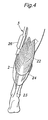
- Figure 4 is an explanatory drawing showing a lower leg support member fitted on a lower leg portion;
- Figure 5 is a perspective view of a principal part of the walking assistance device of the present invention; and
- Figure 6 is a view for explaining the difference in motion between the human body and the assisting device.
- Figure 1 shows a walking assistance device of the present invention as worn on a user's body. The walking assistance device consists of a
hip support member 1, lowerleg support member 2 and adrive unit 3, where thehip support member 1 and the lowerleg support member 2 are secured on a lower limb and a rotational torque generated by thedrive unit 3 is transmitted to the lower limb via the hip and lower leg support members, to whereby provide a force for supplementing a reduced muscle power. - The
hip support member 1 comprises a back support 4,belt portion 5 andlining portion 6, as shown in Figure 2. - Additionally referring to Figure 3, the back support 4 is substantially of the shape of letter-U as seen in plan view so that it abuts a region of the body extending from right and left iliac crests (front ends of the pelvic bone) 7 to the backside of the sacroiliac joint (joint between the vertebrae and pelvic bone) 8, and consists of a substantially rigid body so as to withstand the drive force generated by a
hip joint actuator 10, which consists of an electric motor equipped with a reduction gear or the like and is mounted on a hipdrive source mount 9 provided at each of the right and left ends of the back support 4. A rear portion of the back support 4 has a hollow space so that a control circuit and a battery for supplying electric power to the control circuit as well as to the electric motor are accommodated therein, though not explicitly shown in the drawings. Further, at a portion of the back support 4 that directly abuts the user's body is provided acushioning pad 11. - The
belt portion 5 is made of a relatively rigid material and comprises: a pair of right andleft bases 14 integrally attached by means of bolts to inner sides ofbelt joints 13 provided at right and left side portions of the back support 4; a pair of right andleft web parts 15 fixed to front ends of thebases 14; and a pair of right andleft buckles 16 attached to front ends of theweb parts 15. The inner surface of thebelt portion 5, i.e., the surface facing the hip portion of the user's body, is adapted to be attached with thelining portion 6 for protection by means of loop and hook fastener or the like. - The
cushioning pad 11 provided to the back support 4 comprises acenter pad 18 abutting a depression extending along alumbar vertebra 17 and a pair ofside pads 19 abutting laterally outer regions of erector spinae muscles slightly jutting out backward at right and left of thelumbar vertebra 17. Further, thelining portion 6 comprisesiliac pads 20 abutting theiliac crests 7. Thus, a total of five pads abut principal portions of the hip to keep the back support 4 from moving out of place. Further, because direct contact of the hipdrive source mount 9 with the user's body would cause pain to the user and could impart a large impact on the body if the user happens to fall,hip joint pads 21 are provided to thelining portion 6 so as to be interposed between the user's body and the hipdrive source mount 9 and reduce the impact and pain. - Each of the
web parts 15 comprises a pair of upper and lower plain weave belts secured to theassociated base 14, and the front ends of the belts are joined together and attached to thecorresponding buckle 16 so that they form a shape of letter-V that converges in the front direction. Theupper belt 15U of eachweb part 15 extends from the joint with thebase 14 disposed at a position corresponding to theiliac crest 7 toward thebuckle 16 disposed at an intermediate portion ("tanden") between the navel and pubic bone along a direction of the extension of muscle fibers of the abdominal external oblique muscle. Thelower belt 15L of theweb part 15 extends from the joint with thebase 14 disposed on a side of the hip joint toward thebuckle 16 along a direction of fibers of the abdominal internal oblique muscle. - The upright posture of the spine is maintained by the balance of back muscle, pectoral muscle and abdominal muscle. The weakening of muscles of a person having walking impediment applies not only to the muscles of lower limb but also to the back, pectoral or abdominal muscles. Particularly, the weakening of the abdominal muscle can lower the abdominal cavity and cause the spine to bend in the shape of letter-S as seen in side view, thus making it difficult to maintain the upright posture during walking. According to the device of the present invention, the
buckle 16 is positioned at a center of lower abdomen called "tanden" where the rectus abdominis muscle, abdominal external oblique muscle, abdominal internal oblique muscle, transversus abdominis muscle, etc. which play an important role in keeping the upright posture, overlap each other, and a tightening force is applied to theweb parts 15 so that the back support 4 fitted on a region extending from the right andleft iliac crests 7 to the backside of the secroiliac joint functions to correct the curve of the spine and stabilize the pelvis to achieve a proper posture and at the same time increase the abdominal cavity pressure to lift up the viscera to proper positions. Further, because theweb parts 15 abut the lower abdominal portion with a relatively large contact area, the pressure applied to the abdominal cavity can be distributed evenly over the whole lower abdominal portion, thus reducing the uncomfortable pressure felt by the user. - On the other hand, as also shown in Figure 4, the lower
leg support member 2 comprises a band-like member 24 wound around the region where the skin movement is relatively small during motion of the lower limb joints, i.e., region extending from lateral sides of an upper part of the anterior tibial muscle to the portion between a lower part of thecalf muscle 22 and an upper part of the Achillestendon 23. According to such a structure, it can be avoided to place the principal engagement points of the lowerleg support member 2 on the calf, of which circumferential length can vary with the extension/flexion of the knee, or on the Achilles tendon where the skin moves with the motion of the ankle, and therefore it is possible to securely fasten the lowerleg support member 2 on the lower leg with an abundant tightening force. - Additionally referring to Figure 5, the
drive unit 3 comprises ahip joint actuator 10 and aknee joint actuator 26, each consisting of an electric motor equipped with a reduction gear or the like, where the actuators are attached to either end of a link bar 25 (second linkage means). Thedrive unit 3 is adapted by using a well-known chucking mechanism so as to be able to repeatedly attached and detached with respect to the hipdrive source mount 9 provided to thehip support member 1 at a position corresponding to a side of the hip joint as well as with respect to a kneedrive source mount 27 provided to the lowerleg support member 2 at a position corresponding to a side of the knee joint. - The
link bar 25 comprises anouter tube 28 and aninner rod 29 telescopically connected so as to be slidable relative to each other to allow expansion and contraction of the distance between theactuators 10 and 26 (arrow E). Inside theouter tube 28 is disposed a tension coil spring (not shown in the drawings), for example, so that the spring is connected to theinner rod 29, upon which the weight of theknee joint actuator 26 is applied, to always exert a tensioning force upon theinner rod 29 in a direction to support the weight. In this way, the kneejoint actuator 26 is pulled up toward the hip support member to decrease the force imposed upon the lower leg portion and at the same time prevent the lowerleg support member 2 from slipping down inadvertently. It should be noted that thelink bar 25 is formed along an arc of a constant curvature so as to extend along the side of the thigh. - A
base portion 31 of the hipdrive source mount 9 is attached to a vicinity of the rigid belt joint 13 (Figure 2) via a link plate 30 (first linkage means) made of a flexible material such as an elastomeric material. Thelink plate 30 extends out from a side end portion of the back support 4 obliquely in a forward and downward direction, and mounted by bolts passed throughelongated holes 61 so that the position of thelink plate 30 can be adjustable. This allows a rotation center axis AM of thehip joint actuator 10 to coincide with the hip joint center P of the human body which can vary depending on the build of the user. - The
link plate 30 is adapted, by adjusting the aspect ratio of its cross section, for example, such that thelink plate 30 is hard to deform in the fore and aft direction as well as in the up and down direction to prevent deviation of the rotational center axis AM of thehip joint actuator 10 from the hip joint center P when the thigh is moved in the fore and aft direction (arrow S) to swing thelink bar 25 in the fore and aft direction under the rotational force from thehip joint actuator 10, and such that thelink plate 30 can undergo a bending deformation (arrow B) in the lateral direction (i.e., in a direction of an arc which is tangential to the rotational center axis AM of the hip joint actuator 10) and a torsional deformation (arrow T) which is a deformation around an axis AC perpendicular to the rotational center axis AM so as to accommodate a certain range of change in the axis orientation of thehip joint actuator 10 and allow the support member to follow the lateral motions and twisting motions of the thigh to a certain extent. - By imparting the above degree of freedom to the hip
drive source mount 9 of thehip support member 1 as well as to thelink bar 25 interconnecting theactuators drive unit 3, the positions of thedrive source mounts actuators link plate 30 is adjusted to cross the rotation center axis AM of thehip joint actuator 10, positional deviation of thehip joint actuator 10 with respect to the motion of the thigh can be minimized and the hipdrive source mount 9 can be prevented from pushing or rubbing the user's body. The covers surrounding thelink bar 25 and thelink plate 30 are provided with accordion portions 62, 63 to accommodate the expansion and contraction of thelink bar 25 as well as the bending and torsioning of thelink plate 30. - If the device of the present invention is worn over a spat S for exercise that is adapted to provide a specific muscle(s) with a tightening force that is equivalent to that produced by taping (see Japanese Patent Application Laid-Open No. 2001-214303), the device can function even more effectively to improve the motion ability of the user in cooperation with the muscle support effect resulting from the tightening force produced by the fibers forming the spat S. Also, if the drive torque is effected in reverse, the device of the present invention can apply a load torque upon the joint, and therefore the device can be used not only as a motion assisting device but also as a load generator for medical treatment, rehabilitation or training for muscle development.
- As described above, according to the present invention, the following advantages can be obtained:
- 1. Owing to the structure where the hip joint actuator is mounted to the body via a link plate serving as a first linkage means having at least two degrees of freedom, and the hip joint actuator and the knee joint actuator are connected to each other via a link bar serving as a second linkage means having an expandable and contractable means, deformation in lateral and torsional directions, for example, of the link plate and expansion/contraction of the link bar can absorb a deviation in position between the joints of the user's body and the associated actuators.
- 2. Owing to the structure where the spring means supports a weight of the knee joint rotational force generator and component parts below the knee joint rotational force generator, it is possible to exert a force from the spring means substantially comparable with the weight of the knee joint actuator to pull it up toward the hip whereby the force imposed upon the lower leg portion can be reduced and inadvertent slip of the support member fitted on the lower leg portion can be prevented.
- 3. Because the linkage between the hip joint actuator and the hip support member is embodied by using a flexible member accommodating a positional deviation of the hip joint actuator in a direction of an arc tangential to a rotation center axis of the hip joint actuator, and in a torsional direction around an axis perpendicular to the rotation center axis of the hip joint rotational force generator, it is possible to mount the hip joint actuator to the body so as to be able to follow the torsional movements as well as fore and aft or right and left swinging movements of the hip joint.
- 4. Owing to the structure where an axis of deformation of the link plate for connecting the hip joint actuator to the hip support member crosses the rotation center axis of the hip joint actuator, it is possible to minimize a deviation of motion of the hip joint actuator with respect to the motion of the hip joint.
- Thus, the walking assistance device of the present invention having adjustability and a plurality of degrees of freedom can solve the prior art problem of hampering the free motion of body worn on the user.
Claims (4)
- A walking assistance device comprising a hip joint rotational force generator mounted on a side of a hip joint and a knee joint rotational force generator mounted on a side of a knee joint to provide an assisting force to a movement of a lower limb,
wherein the hip joint rotational force generator is fitted to a body via a first linkage means having at least two degrees of freedom,
and wherein the hip joint rotational force generator and the knee joint rotational force generator are connected to each other via a second linkage means having an expandable and contractable means. - The walking assistance device according to claim 1, wherein the expandable and contractable means comprises a spring means supporting a weight of the knee joint rotational force generator and component parts below the knee joint rotational force generator.
- The walking assistance device according to claim 1, wherein the first linkage means consists of a flexible member accommodating a positional deviation of the hip joint rotational force generator in a direction of an arc which is tangential to a rotation center axis of the hip joint rotational force generator, and in a torsional direction around an axis perpendicular to the rotation center axis of the hip joint rotational force generator.
- The walking assistance device according to claim 3, wherein an axis of deformation of the flexible member crosses the rotation center axis of the hip joint rotational force generator.
Applications Claiming Priority (2)
| Application Number | Priority Date | Filing Date | Title |
|---|---|---|---|
| JP2003143509A JP4112430B2 (en) | 2003-05-21 | 2003-05-21 | Walking assist device |
| PCT/JP2004/003408 WO2004103249A1 (en) | 2003-05-21 | 2004-03-15 | Walking aid device |
Publications (3)
| Publication Number | Publication Date |
|---|---|
| EP1637113A1 true EP1637113A1 (en) | 2006-03-22 |
| EP1637113A4 EP1637113A4 (en) | 2010-02-10 |
| EP1637113B1 EP1637113B1 (en) | 2012-05-09 |
Family
ID=33475129
Family Applications (1)
| Application Number | Title | Priority Date | Filing Date |
|---|---|---|---|
| EP04720747A Expired - Lifetime EP1637113B1 (en) | 2003-05-21 | 2004-03-15 | Walking aid device |
Country Status (4)
| Country | Link |
|---|---|
| US (1) | US7559909B2 (en) |
| EP (1) | EP1637113B1 (en) |
| JP (1) | JP4112430B2 (en) |
| WO (1) | WO2004103249A1 (en) |
Cited By (2)
| Publication number | Priority date | Publication date | Assignee | Title |
|---|---|---|---|---|
| EP2168548A1 (en) * | 2005-05-27 | 2010-03-31 | Honda Motor Co., Ltd. | Walking assisting device |
| WO2016166442A1 (en) | 2015-04-16 | 2016-10-20 | Aplinov | Movement assistance device |
Families Citing this family (43)
| Publication number | Priority date | Publication date | Assignee | Title |
|---|---|---|---|---|
| US6966882B2 (en) | 2002-11-25 | 2005-11-22 | Tibion Corporation | Active muscle assistance device and method |
| JP4008465B2 (en) * | 2005-09-02 | 2007-11-14 | 本田技研工業株式会社 | Motion induction device |
| JP4603479B2 (en) * | 2005-12-09 | 2010-12-22 | 本田技研工業株式会社 | Force transmission member |
| JP4736946B2 (en) * | 2006-05-19 | 2011-07-27 | トヨタ自動車株式会社 | Walking aid |
| JP4712627B2 (en) * | 2006-07-10 | 2011-06-29 | 本田技研工業株式会社 | Walking assist device |
| US8353854B2 (en) | 2007-02-14 | 2013-01-15 | Tibion Corporation | Method and devices for moving a body joint |
| WO2009014644A1 (en) | 2007-07-20 | 2009-01-29 | Ossur Hf | Prosthetic or orthopedic device having feedback |
| KR100950060B1 (en) * | 2007-08-30 | 2010-04-02 | 한정수 | Rehabilitation Equipment for Complex Joint Exercise |
| WO2009099671A2 (en) * | 2008-02-08 | 2009-08-13 | Tibion Corporation | Multi-fit orthotic and mobility assistance apparatus |
| CA2724085C (en) * | 2008-05-20 | 2018-10-16 | Berkeley Bionics | Device and method for decreasing energy consumption of a person by use of a lower extremity exoskeleton |
| AU2009282397B2 (en) * | 2008-05-20 | 2014-10-09 | Ekso Bionics, Inc. | Device and method for decreasing oxygen consumption of a person during steady walking by use of a load-carrying exoskeleton |
| US20090306548A1 (en) | 2008-06-05 | 2009-12-10 | Bhugra Kern S | Therapeutic method and device for rehabilitation |
| JP5021574B2 (en) * | 2008-06-19 | 2012-09-12 | 本田技研工業株式会社 | Walking assist device |
| US8274244B2 (en) | 2008-08-14 | 2012-09-25 | Tibion Corporation | Actuator system and method for extending a joint |
| US8058823B2 (en) | 2008-08-14 | 2011-11-15 | Tibion Corporation | Actuator system with a multi-motor assembly for extending and flexing a joint |
| JP5313609B2 (en) * | 2008-09-26 | 2013-10-09 | 国立大学法人 筑波大学 | Frame structure of wearable motion assist device. |
| US20100198124A1 (en) * | 2009-01-30 | 2010-08-05 | Kern Bhugra | System and method for controlling the joint motion of a user based on a measured physiological property |
| US8639455B2 (en) | 2009-02-09 | 2014-01-28 | Alterg, Inc. | Foot pad device and method of obtaining weight data |
| CN104853712B (en) * | 2012-12-14 | 2017-07-28 | 国立大学法人名古屋工业大学 | Walking auxiliary machine |
| CN103054692B (en) * | 2013-01-29 | 2015-03-04 | 苏州大学 | Wearable lower limb exoskeleton walking-assisted robot |
| US9675514B2 (en) * | 2013-03-15 | 2017-06-13 | Bionik Laboratories, Inc. | Transmission assembly for use in an exoskeleton apparatus |
| WO2014151584A1 (en) | 2013-03-15 | 2014-09-25 | Alterg, Inc. | Orthotic device drive system and method |
| US9855181B2 (en) | 2013-03-15 | 2018-01-02 | Bionik Laboratories, Inc. | Transmission assembly for use in an exoskeleton apparatus |
| CN105899178A (en) | 2014-01-15 | 2016-08-24 | 松下电器产业株式会社 | Lower Limb Support Tool |
| US10449105B2 (en) * | 2014-10-26 | 2019-10-22 | Springactive, Inc. | System and method of bidirectional compliant joint torque actuation |
| KR102346198B1 (en) * | 2015-01-07 | 2021-12-31 | 삼성전자주식회사 | A driving module and a motion assist apparatus comprising thereof |
| MX388230B (en) * | 2015-02-09 | 2025-03-19 | Scuola Superiore Di Studi Univ E Di Perfezionamento Santanna | ACTUATION SYSTEM FOR HIP ORTHOSIS. |
| JP1541976S (en) * | 2015-05-18 | 2016-01-18 | ||
| KR101641883B1 (en) * | 2015-05-22 | 2016-07-22 | 웨어러텍(주) | Apparatus for joint brace |
| CN105105988B (en) * | 2015-09-22 | 2017-05-31 | 谷林电器(深圳)有限公司 | Device of walking aid |
| EP3158893B1 (en) * | 2015-10-21 | 2021-04-28 | noonee AG | Seat unit for wearable sitting posture assisting device |
| KR102395796B1 (en) | 2015-11-06 | 2022-05-10 | 삼성전자주식회사 | A power transmitting module and a motion assist apparatus comprising thereof |
| EP3173053B1 (en) | 2015-11-26 | 2025-04-09 | Samsung Electronics Co., Ltd. | Motion assistance apparatus including a frame assembly |
| WO2017203736A1 (en) * | 2016-05-25 | 2017-11-30 | ボッシュ株式会社 | Motion assist device |
| CN106420270B (en) * | 2016-08-15 | 2019-04-30 | 江苏大学 | A wearable lower limb assist mechanism |
| JP6508167B2 (en) * | 2016-11-11 | 2019-05-08 | トヨタ自動車株式会社 | Walking training system |
| KR102809156B1 (en) | 2016-11-29 | 2025-05-16 | 삼성전자주식회사 | Motion assist apparatus |
| CN106821687B (en) * | 2017-01-12 | 2019-04-23 | 北京协同创新研究院 | A kind of wearable power joint recovering device |
| CN106806089B (en) * | 2017-01-12 | 2019-04-23 | 北京协同创新研究院 | A kind of wearable power joint recovering device of gear-rack drive |
| DE102017121343A1 (en) * | 2017-09-14 | 2019-03-14 | Otto Bock Healthcare Products Gmbh | joint device |
| WO2019164349A1 (en) | 2018-02-23 | 2019-08-29 | Lg Electronics Inc. | Wearable assistive device that efficiently delivers assistive force |
| WO2019198269A1 (en) * | 2018-04-13 | 2019-10-17 | 本田技研工業株式会社 | Walking assist device |
| US11918475B2 (en) | 2021-03-31 | 2024-03-05 | DePuy Synthes Products, Inc. | Modular acetabular surgical implant assembly |
Family Cites Families (15)
| Publication number | Priority date | Publication date | Assignee | Title |
|---|---|---|---|---|
| JPS53142400A (en) | 1977-05-18 | 1978-12-12 | Tokuyama Soda Co Ltd | Production of alkali-containing silicate |
| FR2506604A1 (en) * | 1981-06-01 | 1982-12-03 | Salort Guy | EXTERNAL VERTICAL AND MARKET STATION APPARATUS FOR DISABLED MOTORS OF THE LOWER LIMBS |
| JPS58163364A (en) | 1982-03-23 | 1983-09-28 | 工業技術院長 | Power accessory for lower limb disabled person |
| JPS60199450A (en) * | 1984-03-26 | 1985-10-08 | 工業技術院長 | Power mount for lower limb disabled person |
| JPS61228854A (en) | 1985-04-02 | 1986-10-13 | 工業技術院長 | Power mount device of artificial leg |
| GB2206494B (en) | 1987-06-24 | 1991-04-17 | Steeper Hugh Ltd | Orthoses or prostheses for co-ordinating limb movement |
| US4964628A (en) * | 1989-06-30 | 1990-10-23 | Center For Orthotics Design, Inc. | Hip-reciprocating apparatus |
| US5020790A (en) * | 1990-10-23 | 1991-06-04 | Board Of Supervisors Of Louisiana State University And Agricultural And Mechanical College | Powered gait orthosis |
| JP3032086B2 (en) | 1992-07-02 | 2000-04-10 | 技術研究組合医療福祉機器研究所 | Bilateral long leg orthosis |
| US5476441A (en) * | 1993-09-30 | 1995-12-19 | Massachusetts Institute Of Technology | Controlled-brake orthosis |
| WO2000028927A1 (en) * | 1998-11-13 | 2000-05-25 | Hocoma Ag | Device and method for automating treadmill therapy |
| JP3740344B2 (en) | 2000-02-03 | 2006-02-01 | 株式会社ワコール | Exercise spats |
| US6589195B1 (en) * | 2000-05-26 | 2003-07-08 | Orthomerica Products, Inc. | Modular adjustable prophylactic hip orthosis and adduction/abduction joint |
| JP2002301124A (en) * | 2001-04-06 | 2002-10-15 | Honda Motor Co Ltd | Walking aid |
| US7153242B2 (en) * | 2001-05-24 | 2006-12-26 | Amit Goffer | Gait-locomotor apparatus |
-
2003
- 2003-05-21 JP JP2003143509A patent/JP4112430B2/en not_active Expired - Fee Related
-
2004
- 2004-03-15 EP EP04720747A patent/EP1637113B1/en not_active Expired - Lifetime
- 2004-03-15 US US10/557,731 patent/US7559909B2/en not_active Expired - Fee Related
- 2004-03-15 WO PCT/JP2004/003408 patent/WO2004103249A1/en not_active Ceased
Cited By (4)
| Publication number | Priority date | Publication date | Assignee | Title |
|---|---|---|---|---|
| EP2168548A1 (en) * | 2005-05-27 | 2010-03-31 | Honda Motor Co., Ltd. | Walking assisting device |
| US8114034B2 (en) | 2005-05-27 | 2012-02-14 | Honda Motor Co., Ltd. | Walking assisting device |
| WO2016166442A1 (en) | 2015-04-16 | 2016-10-20 | Aplinov | Movement assistance device |
| US10537150B2 (en) | 2015-04-16 | 2020-01-21 | Aplinov | Movement assistance device |
Also Published As
| Publication number | Publication date |
|---|---|
| EP1637113A4 (en) | 2010-02-10 |
| EP1637113B1 (en) | 2012-05-09 |
| JP4112430B2 (en) | 2008-07-02 |
| WO2004103249A1 (en) | 2004-12-02 |
| US7559909B2 (en) | 2009-07-14 |
| JP2004344306A (en) | 2004-12-09 |
| US20070106190A1 (en) | 2007-05-10 |
Similar Documents
| Publication | Publication Date | Title |
|---|---|---|
| EP1637113B1 (en) | Walking aid device | |
| EP1637115B1 (en) | Walking aid device | |
| US7481742B2 (en) | Walking assistance device | |
| EP1637116B1 (en) | Walk assisting device | |
| EP1637114B1 (en) | Walking aid device | |
| JP5075759B2 (en) | Walking assist device | |
| US10028881B2 (en) | Swinging leg pendulum movement aid for walking, and assistance force control method | |
| CN101808604B (en) | Femoral support member for a walking assistance device | |
| KR102541908B1 (en) | A frame module and a motion assist apparatus comprising thereof | |
| JPH0112492B2 (en) | ||
| JP4112542B2 (en) | Wearing device for walking assist device | |
| JP4112541B2 (en) | Wearing device for walking assist device | |
| EP4364712B1 (en) | Motion assistance apparatus |
Legal Events
| Date | Code | Title | Description |
|---|---|---|---|
| PUAI | Public reference made under article 153(3) epc to a published international application that has entered the european phase |
Free format text: ORIGINAL CODE: 0009012 |
|
| 17P | Request for examination filed |
Effective date: 20051220 |
|
| AK | Designated contracting states |
Kind code of ref document: A1 Designated state(s): DE FR GB |
|
| DAX | Request for extension of the european patent (deleted) | ||
| RBV | Designated contracting states (corrected) |
Designated state(s): DE FR GB |
|
| A4 | Supplementary search report drawn up and despatched |
Effective date: 20100112 |
|
| RIC1 | Information provided on ipc code assigned before grant |
Ipc: A61F 5/01 20060101ALI20100105BHEP Ipc: A61H 3/00 20060101AFI20041210BHEP |
|
| 17Q | First examination report despatched |
Effective date: 20100507 |
|
| GRAP | Despatch of communication of intention to grant a patent |
Free format text: ORIGINAL CODE: EPIDOSNIGR1 |
|
| RIC1 | Information provided on ipc code assigned before grant |
Ipc: A61H 3/00 20060101AFI20111223BHEP Ipc: A61F 5/01 20060101ALI20111223BHEP |
|
| RIN1 | Information on inventor provided before grant (corrected) |
Inventor name: KATO, HISASHI,C/O KABUSHIKI KAISHA HONDA GIJUTSU Inventor name: HIRATA, TAKASHI,C/O KABUSHIKI KAISHA HONDA GIJUTSU |
|
| GRAS | Grant fee paid |
Free format text: ORIGINAL CODE: EPIDOSNIGR3 |
|
| GRAA | (expected) grant |
Free format text: ORIGINAL CODE: 0009210 |
|
| AK | Designated contracting states |
Kind code of ref document: B1 Designated state(s): DE FR GB |
|
| REG | Reference to a national code |
Ref country code: GB Ref legal event code: FG4D |
|
| REG | Reference to a national code |
Ref country code: DE Ref legal event code: R096 Ref document number: 602004037758 Country of ref document: DE Effective date: 20120705 |
|
| PLBE | No opposition filed within time limit |
Free format text: ORIGINAL CODE: 0009261 |
|
| STAA | Information on the status of an ep patent application or granted ep patent |
Free format text: STATUS: NO OPPOSITION FILED WITHIN TIME LIMIT |
|
| 26N | No opposition filed |
Effective date: 20130212 |
|
| PGFP | Annual fee paid to national office [announced via postgrant information from national office to epo] |
Ref country code: DE Payment date: 20130326 Year of fee payment: 10 |
|
| REG | Reference to a national code |
Ref country code: DE Ref legal event code: R097 Ref document number: 602004037758 Country of ref document: DE Effective date: 20130212 |
|
| GBPC | Gb: european patent ceased through non-payment of renewal fee |
Effective date: 20130315 |
|
| REG | Reference to a national code |
Ref country code: FR Ref legal event code: ST Effective date: 20131129 |
|
| PG25 | Lapsed in a contracting state [announced via postgrant information from national office to epo] |
Ref country code: FR Free format text: LAPSE BECAUSE OF NON-PAYMENT OF DUE FEES Effective date: 20130402 Ref country code: GB Free format text: LAPSE BECAUSE OF NON-PAYMENT OF DUE FEES Effective date: 20130315 |
|
| REG | Reference to a national code |
Ref country code: DE Ref legal event code: R119 Ref document number: 602004037758 Country of ref document: DE |
|
| REG | Reference to a national code |
Ref country code: DE Ref legal event code: R119 Ref document number: 602004037758 Country of ref document: DE Effective date: 20141001 |
|
| PG25 | Lapsed in a contracting state [announced via postgrant information from national office to epo] |
Ref country code: DE Free format text: LAPSE BECAUSE OF NON-PAYMENT OF DUE FEES Effective date: 20141001 |