EP1636882B1 - Vorrichtung zur bereitstellung optischer strahlung - Google Patents
Vorrichtung zur bereitstellung optischer strahlung Download PDFInfo
- Publication number
- EP1636882B1 EP1636882B1 EP04743063A EP04743063A EP1636882B1 EP 1636882 B1 EP1636882 B1 EP 1636882B1 EP 04743063 A EP04743063 A EP 04743063A EP 04743063 A EP04743063 A EP 04743063A EP 1636882 B1 EP1636882 B1 EP 1636882B1
- Authority
- EP
- European Patent Office
- Prior art keywords
- cladding
- star
- fibre
- core
- circular
- Prior art date
- Legal status (The legal status is an assumption and is not a legal conclusion. Google has not performed a legal analysis and makes no representation as to the accuracy of the status listed.)
- Expired - Lifetime
Links
Images


Classifications
-
- H—ELECTRICITY
- H01—ELECTRIC ELEMENTS
- H01S—DEVICES USING THE PROCESS OF LIGHT AMPLIFICATION BY STIMULATED EMISSION OF RADIATION [LASER] TO AMPLIFY OR GENERATE LIGHT; DEVICES USING STIMULATED EMISSION OF ELECTROMAGNETIC RADIATION IN WAVE RANGES OTHER THAN OPTICAL
- H01S3/00—Lasers, i.e. devices using stimulated emission of electromagnetic radiation in the infrared, visible or ultraviolet wave range
- H01S3/05—Construction or shape of optical resonators; Accommodation of active medium therein; Shape of active medium
- H01S3/06—Construction or shape of active medium
- H01S3/063—Waveguide lasers, i.e. whereby the dimensions of the waveguide are of the order of the light wavelength
- H01S3/067—Fibre lasers
- H01S3/06708—Constructional details of the fibre, e.g. compositions, cross-section, shape or tapering
- H01S3/06729—Peculiar transverse fibre profile
-
- H—ELECTRICITY
- H01—ELECTRIC ELEMENTS
- H01S—DEVICES USING THE PROCESS OF LIGHT AMPLIFICATION BY STIMULATED EMISSION OF RADIATION [LASER] TO AMPLIFY OR GENERATE LIGHT; DEVICES USING STIMULATED EMISSION OF ELECTROMAGNETIC RADIATION IN WAVE RANGES OTHER THAN OPTICAL
- H01S3/00—Lasers, i.e. devices using stimulated emission of electromagnetic radiation in the infrared, visible or ultraviolet wave range
- H01S3/09—Processes or apparatus for excitation, e.g. pumping
- H01S3/091—Processes or apparatus for excitation, e.g. pumping using optical pumping
- H01S3/094—Processes or apparatus for excitation, e.g. pumping using optical pumping by coherent light
- H01S3/094003—Processes or apparatus for excitation, e.g. pumping using optical pumping by coherent light the pumped medium being a fibre
- H01S3/094007—Cladding pumping, i.e. pump light propagating in a clad surrounding the active core
Definitions
- This invention relates to an apparatus for providing optical radiation.
- the invention can take various forms, for example a laser, an optical amplifier, a source of amplified spontaneous emission, or a master oscillator power amplifier.
- the invention has application for materials processing.
- Pulsed NdYAG lasers are widely used in industrial processes such as weld ing, cutting and marking. Care has to be taken in these processes to ensure that the plasmas generated by the laser does not interfere with the incoming laser pulses.
- the relatively low pulse repetition rates (6kHz) at high peak powers that are achievable in a NdYAG laser have led to their wide application in laser machining.
- Fibre lasers are increasingly being used for materials processing applications such as welding, cutting and marking. Their advantage include high efficiency, robustness and high beam quality. Examples include femtosecond lasers for multiphoton processing such as the imaging of biological tissues, Q-switched lasers for machining applications, and high-power continuous-wave lasers. Their disadvantage is their relatively low energy storage capacity as compared to NdYAG lasers.
- fibre lasers need to compete with the more mature diode pumped solid state lasers. In order to do so, much greater optical powers need to be achieved, with high reliability and lower cost.
- Fibre lasers are typically longer than diode-pumped solid state lasers, and this leads to non-linear limitations such as Raman scattering becoming problematical. It would be advantageous to have fibre lasers that are shorter.
- Fibre lasers are typically pumped with diode lasers in bar or stack form, or by many single-emitter diodes that are combined together.
- Fibre lasers can be core pumped, in which case the pump radiation is guided by the core of the active fibre, or cladding pumped, in which case the pump radiation is guided by the cladding of the active fibre.
- the active fibre in a cladding-pumped fibre laser needs to be longer than in a core-pumped fibre laser in order to absorb the pump mediation. This is because there is less interaction between the pump radiation and the core in a cladding pumped fibre laser than in a core-pumped fibre laser.
- the length of active fibre needs to be longer by the ratio of the cladding cross-sectional area and the core cross-sectional area in order to absorb the pump radiation and provide the necessary output energy.
- Cladding pumped fibre lasers that have been described in the prior art have inner claddings that are either rectangular, have flats machined on them, have a shape such as a polygon, or are asymmetric.
- US 4815079 discloses a cladding pumped fibre having a rectangular cladding and another cladding pumped fibre having a circular cladding with an offset core. These designs increase the coupling of pump radiation guided by the cladding and the fibres core.
- the fibres do not have the combination of a central core and a uniform cladding diameter, which make them difficult to cleave and couple radiation in connectors.
- US 5533163 discloses a claddings pumped fibre having an inner cladding in the form of a non-rectangular, convex polygon so that the propagating pump energy is induced to from an essentially uniform radiation field in which the various radiation modes comprising the pump energy are isotropically distributed.
- the fibres do not have the combination of a central core and a uniform cladding diameter, which make them difficult to cleave and couple radiation in connectors.
- US 5864645 discloses a circular cladding pumped fibre having at least one flat t extending along its length to break circular symmetry and to set up chaotic ray behaviour.
- US 5864645 discloses a circular cladding pumped fibre having at least one flat amounting to 1% to 49% of the pump core diameter and which extends along its length to break circular symmetry and to set up chaotic ray behaviour.
- a ground portion amounting to only 1% of the diameter of the pump core does not provide sufficient mode coupling of then pump core modes to improve pump light absorption appreciably.
- D,ahaped fibres reported in the literature that have good pump light absorption have a ground portion amounting to around 10% of the pump diameter of the pump core. Such a fibre can be awkward to cleave, the fibre tending to twist when clamped leading to undesirable angled cleaves.
- None of the above mentioned prior art shapes provides high coupling of cladding modes with the core modes whilst also combining a substantially regular geometry with curved outside edges that is suitable for cleaving, incorporating into optical fibre connectors, and coupling radiation from substantially round sources.
- An aim of the present invention is to provide an apparatus for providing optical radiation that reduces the above aforementioned problem.
- apparatus for providing optical radiation which apparatus comprises an optical fibre having core, a first cladding and a second cladding, characterised in that the first cladding is non-circular and has a substantially constant diameter in its cross-section.
- a first cladding having a substantially constant diameter makes the fibre more suitable for cleaving.
- Fibre cleavers clamp fibres with mechanical devices. Fibres not having a constant diameter can twist during this process.
- a fibre with a substantially constant diameter is advantageous and provides distinct advantages over the prior art.
- the first cladding may have at least one axis of mirror symmetry.
- the first cladding may have a geometric centre.
- the core may be located at the geometric centre. Having a fibre with a core in its geometric centre facilitates coupling of optical radiation in connectors and splices.
- the core may be offset from the geometric centre which may be advantageous in certain circumstances - for example in coupling to another fibre having an offset core, or for increasing mode coupling in certain fibre geometries.
- the core may be centred at the centre of the smallest imaginary circle that can contain the first cladding.
- the core may be offset from the centre of the largest imaginary circle that can be contained within the first cladding.
- the first cladding may comprise circular arcs having centres at the vertices of an equilateral star.
- the circular arcs may have a first radius equal to the length of the side of the star.
- the circular arcs may each have a first radius greater than the length of the side of the star, which circular arcs are joined by circular arcs each having a centre located at the vertices, and a second radius equal to the difference between the first radius and the length of the side of the star.
- Each line of the star preferably crosses all the other lines of the star.
- the star may be an equiangular star.
- the star may contain at least two different angles.
- the star preferably contains an odd number of vertices.
- the fibre may contain at least one longitudinally extended hole.
- the hole may be circular.
- the bole may be non-circular.
- the fibre may contain at least one region of low refractive the region of low refractive index may be circular. Alternatively, or in addition, the region of low refractive index may be non-circular.
- the fibre may comprise rare-earth dopant.
- the rare earth doping may be selected from the group comprising Ytterbium, Erbium, Neodymium, Praseodymium, Thulium, Samarium, Holmium and Dysprosium, Erbium codoped with Ytterbium, or Neodymium codoped with Ytterbium.
- the apparatus may comprise a pump source for providing pump radiation coupled to the first cladding.
- the apparatus may be in the form of a laser, an amplifier, a source of amplified spontaneous emission, or a master oscillator power amplifier.
- the refractive index of the core is greater than the refractive index of the first cladding. It is also preferred that the first cladding has a higher refractive index than the second cladding.
- the first cladding may be a glass such as a silica, doped silica, or a phosphate glass.
- the second cladding may be a polymer, silica, a doped silica, a fluorosilicate, or a doped phosphate glass. If the second cladding is a glass, then it is preferred that the second cladding is coated with a polymer.
- apparatus for providing optical radiation which apparatus comprises an optical fibre 5 having a core 3, a first cladding 1 and a second cladding 2, in which the first cladding 1 has a substantially constant diameter 9 in its cross-section.
- diameter 9 it is meant the diameter or width of the first cladding 1.
- the refractive index of the core is greater than the refractive index of the first cladding 1 which has a higher refractive index than the second cladding 2.
- the first cladding 1 may be a glass such as a silica, doped silica, or a phosphate glass.
- the second cladding 2 may be a polymer, silica, a doped silica, a fluorosilicate, or a doped phosphate glass. If the second cladding 2 is a glass, then it is preferred that the second cladding 2 is coated with a polymer.
- the shape of the first cladding 1 shown in Figure 1 is known as a Reuleaux triangle. It is non-circular, and has the property that it has constant diameter. It has three vortices 6, each of which acts as the centre for the opposite circular arc 7 which connects adjacent vortices 6.
- FIG. 2 An advantage of utilizing such a first cladding 1 is illustrated in Figure 2 which shows a light ray 20 (assumed propagating longitudinally along the fibre 5) being totally internally reflected at the interface 21 between the first cladding 1 and the second cladding 2.
- the ray 20 would be a so-called whispering gallery made, reflecting at a uniform angle, and never intersecting the core 3.
- the ray 20 reflects at higher angles such that it intercepts the core 20 several times in the example shown. The result is a higher degree of overlap of rays propagating along the first cladding 1 with the core 3, which is advantageous for a cladding pumped fibre laser or amplifier because this equates to a shorter length over which pump energy is absorbed by the core 3.
- first claddings 31, 41, 51, 61, 71, 81, 91, and 101 shown in Figures 3 to 10 are first claddings 31, 41, 51, 61, 71, 81, 91, and 101 shown in Figures 3 to 10 .
- the first claddings 31,41, 51, and 61 have both rotational and mirror symmetry.
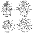
- the first claddings 71 and 81 have only one axis 77 of mirror symmetry.
- the first claddings 91 and 101 shown in Figures 9 and 10 have no axis of mirror symmetry.
- the first cladding 31 is defined by an equilateral star 32 comprising three lines 33, three vertices 35, and defined by a first length 34 equal to the length of the side of the star 32.
- the first cladding 31 comprises circular arcs 36 connecting adjacent vertices 35, the circular arcs 36 having centres 37 at the vertices 35 of the equilateral star 32.
- the circular arcs 35 have a first radius 38 equal to the first length 34.
- Figure 4 shows a first cladding 41 defined by circular arcs 42 and 43.
- the circular arcs 42 are centred on the vertices 35, have a first radius 38 that is greater than the first length 34, and connect adjacent lines 33.
- the circular arcs 42 are joined together with circular arcs 43 each centred at the vertices 35 and each having a second radius 44 equal to the difference between the first radius 38 and the first length 34.
- Figures 5 and 6 show first claddings 51 and 61 similar to the first claddings 31 and 41 respectively, but with five vertices 35 instead of three vertices 35.
- the equilateral stars 32 shown in Figures 3,4, 5 and 6 are equiangular stars.
- Figures 7 and 8 show first claddings 71 and 81 similar to first claddings 51 and 52 respectively, but where the equilateral stars 32 contain at least two different angles 75, 76, that is, the equilateral stars 32 are not equiangular stars.
- the first claddings 71. and 81 contain an axis of mirror symmetry 77.
- Figures 9 and 10 show first claddings 91 and 101 defined by equilateral star 32 characterised in having no axes of mirror symmetry.
- the stars 32 shown in Figures 3 to 10 all have an odd number of vertices 35. In general the number of vertices 35 should be odd, and can be between three and one hundred and three, but is preferably between three and nine. Each of the lines 33 that make up the stars 32 in Figures 3 to 10 cross each of the other lines 33.
- Figure 11 shows a fibre 110 containing the first cladding 51.
- the core 3 is located at the geometric centre 111 of the first cladding 51 that is defined by the intersect of two of the lines of mirror symmetry 77.
- the core 3 can also be offset from the geometric centre 111.
- the cores 3 in both Figures 11 and 12 are shown as being concentric with the second cladding 2 which can sometimes be convenient for locating the core 3 and/or for splicing the fibre 110, 120, especially if the second cladding 2 is made from a hard material such as a glass.
- the first claddings 91 and 101 shown with reference to Figures 9 and 10 do not have lines of mirror symmetry 77 and do not have geometric centres.
- Figure 13 shows a fibre 130 comprising the first cladding 101.
- a circle 131 is defined which is the smallest circle that can contain the first cladding 101.
- the core 3 may be centred at the centre 132 of the circle 131. This location is advantageous for splicing the fibre 130. Alternatively, the core 3 may be offset from the centre of the circle 131 which in certain configurations may be advantageous for maximising the overlap between cladding modes and the core.
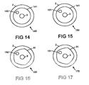
- Figure 14 shows a fibre 140 comprising a circular first cladding 141 which contains a longitudinally extended hole 142.
- the hole 142 maybe circular or non-circular.
- the hole 142 may be elliptical or substantially rectangular. The hole 142 will assist in coupling cladding modes with the core 3.
- Figure 15 shows a fibre 150 containing a region 151 of low refractive index in the first cladding 141.
- low refractive index it is meant that the refractive index of the region 151 is less than that of the first cladding 141.
- the region 151. of low refractive index may be circular. Alternatively, or in addition, the region 15 of low refractive index may be non-circular.
- the region 151 of low refractive index may be boron doped silica, and may be a stress rod manufactured using modified vapour chemical deposition,
- Figures 16 and 17 show similar fibres 160,170 to those shown in Figures 14 and 15 but with the non-circular first cladding 51,
- the fibre 5 preferably comprises rare-earth dopant 10.
- the rare earth dopant 10 may be selected from the group comprising Ytterbium, Erbium, Neodymium, Praseodymium, Thulium, Samarium, Holmium and Dysprosium, Erbium codoped with Ytterbium, or Neodymium codoped with Ytterbium.
- the rare earth dopant 10 may be located in the core 3, in the first cladding 1, or in both the core 3 and the first cladding 1.
- Fibres 110, 120, 130, 140, 150, 160 and 170 preferably contain rare-earth dopant 10.
- Fibres containing a first cladding 1 as described with reference to the above figures can be fabricated by inserting a modified chemical vapour deposition perform into a pre-machined glass capillary having the desired outer contour and materials properties.
- the machining can be performed using ultrasonic milling and/or lapping.
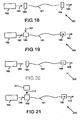
- Figure 18 shows apparatus for providing optical radiation 189 in the form of a laser 180 comprising a fibre 181 and a pump source 182 for providing pump radiation 185 to the first cladding 1, and first and second reflectors 183, 184.
- the fibre 181 is preferably one of the fibres described with reference to Figures 1 to 17 that contains rare earth dopant 10.
- the pump source 182 can comprise at least one semiconductor laser diode, a laser diode bar or a laser diode stack.
- the reflectors 183 and 184 can comprise a fibre Bragg grating, a grating, a dichroic mirror, or an end reflection from the fibre 181. It is preferable that the reflection of the first reflector 183 is greater than the reflection of the second reflector.
- the first reflector 183 is preferably dichroic, reflecting light at the wavelength of the optical radiation 189, and transmitting the pump radiation 185.
- the fibre 181 can be multimode or monomode optical fibre.
- Figure 19 shows apparatus for providing optical radiation 195 in the form of an optical amplifier 190.
- the amplifier 190 is similar to that shown in Figure 18 except that there are no reflectors 183. 134.
- Pump radiation 185 and signal 191 are coupled into the fibre 131 by a coupler 193.
- the coupler 193 may be any form of optical combining means such as a beam splitter or coupler, but is preferably a dichroic mirror or wavelength division multiplexing coupler.
- the optical amplifier 190 can include one or more isolators 196.
- Figure 20 shows apparatus for providing optical radiation 205 in the form of a source of amplified spontaneous emission 200 that comprises the pump source 1 82 and the fibre 181.
- the source 200 may also contain one or both of the isolator 196 and reflector 183.
- Figure 21 shows apparatus for providing optical radiation 215 in the form of a master oscillator power amplifier 210 comprising the pump source 182, the fibre 181, and a seed source 211 for providing an optical seed 212.
- the seed source 211 may be a semiconductor laser, a pulsed laser, a fibre laser, or a solid state laser.
- a semiconductor laser is often desirable in this application because the amplitude of the optical seed 212, and hence the optical radiation 215 can be controlled to a desired shape by modulating the drive current into the semiconductor laser.
- the provision of the isolator 196 is optional.
- the laser 180, the amplifier 190, the source of amplified spontaneous emission, 200, and the mater oscillator power amplifier 210 are believed to have important application as sources of high power laser radiation for industrial and aerospace applications including materials processing. In such applications it is often desirable to synchronise the pump source 182 with the movement of an optical scanner.
- the present invention extends to the above-mentioned features taken in isolation or in any combination.
Landscapes
- Physics & Mathematics (AREA)
- Electromagnetism (AREA)
- Engineering & Computer Science (AREA)
- Plasma & Fusion (AREA)
- Optics & Photonics (AREA)
- Lasers (AREA)
- Laser Surgery Devices (AREA)
- Glass Compositions (AREA)
- Surgical Instruments (AREA)
- Optical Couplings Of Light Guides (AREA)
Claims (24)
- Vorrichtung zur Bereitstellung optischer Strahlung, wobei die Vorrichtung eine Lichtleitfaser mit einem Kern, einem ersten Mantel und einem zweiten Mantel umfasst, dadurch gekennzeichnet, dass der erste Mantel nicht kreisförmig ist und einen konstanten Durchmesser im Querschnitt hat.
- Vorrichtung nach Anspruch 1, bei der der erste Mantel mindestens eine Spiegelsymmetrieachse hat.
- Vorrichtung nach einem der vorhergehenden Ansprüche, bei der der erste Mantel ein geometrisches Zentrum hat.
- Vorrichtung nach Anspruch 3, bei der sich der Kern im geometrischen Zentrum befindet.
- Vorrichtung nach Anspruch 3, bei der sich der Kern vom geometrischen Zentrum versetzt befindet.
- Vorrichtung nach Anspruch 1 oder Anspruch 2, bei der sich der Kern im Zentrum des kleinsten imaginären Kreises befindet, der den ersten Mantel enthalten kann.
- Vorrichtung nach Anspruch 1 oder Anspruch 2, bei der sich der Kern vom Zentrum des größten imaginären Kreises versetzt befindet, der in dem ersten Mantel enthalten sein kann.
- Vorrichtung nach einem der vorhergehenden Ansprüche, bei der der erste Mantel kreisförmige Bögen mit Zentren an den Vertices eines gleichseitigen Sterns umfasst.
- Vorrichtung nach Anspruch 8, wobei die kreisförmigen Bögen jeweils einen ersten Radius haben, der gleich der Länge der Seite des Sterns ist.
- Vorrichtung nach Anspruch 8, bei der die kreisförmigen Bögen jeweils einen ersten Radius, der größer ist als die Länge der Seite des Sterns, wobei sich kreisförmige Bögen mit einem an den Vertices befindlichen Zentrum an die kreisförmigen Bögen anschließen, und einen zweiten Radius haben, der gleich der Differenz zwischen dem ersten Radius und der Länge der Seite des Sterns ist.
- Vorrichtung nach einem der Ansprüche 8 bis 10, bei der jede Linie des Sterns alle anderen Linien des Sterns schneidet.
- Vorrichtung nach Anspruch 11, bei der der Stern ein gleichwinkliger Stern ist.
- Vorrichtung nach Anspruch 11, bei der der Stern mindestens zwei unterschiedliche Winkel enthält.
- Vorrichtung nach einem der Ansprüche 8 bis 13, bei der der Stern eine ungerade Anzahl an Vertices enthält.
- Vorrichtung nach einem der vorhergehenden Ansprüche, bei der die Faser mindestens ein sich längs erstrecktes Loch enthält.
- Vorrichtung nach Anspruch 15, bei der das Loch kreisförmig ist.
- Vorrichtung nach Anspruch 15, bei der das Loch nicht kreisförmig ist.
- Vorrichtung nach einem der vorhergehenden Ansprüche, bei der die Faser mindestens einen Bereich mit niedrigem Brechungsindex enthält.
- Vorrichtung nach Anspruch 18, bei der der Bereich mit niedrigem Brechungsindex kreisförmig ist.
- Vorrichtung nach Anspruch 18, bei der der Bereich mit niedrigem Brechungsindex nicht kreisförmig ist.
- Vorrichtung nach einem der vorhergehenden Ansprüche, wobei die Faser ein Seltenerddotiermittel umfasst.
- Vorrichtung nach Anspruch 21, bei der das Seltenerddotiermittel ausgewählt ist aus der Gruppe bestehend aus Ytterbium, Erbium, Neodymium, Praseodymium, Thulium, Samarium, Holmium, und Dysprosium, mit Ytterbium codotiertem Erbium oder mit Ytterbium codotiertem Neodymium.
- Vorrichtung nach einem der vorhergehenden Ansprüche, umfassend eine an den ersten Mantel angekoppelte Pumpenquelle zur Bereitstellung von Pumpstrahlung.
- Vorrichtung nach einem der vorhergehenden Ansprüche, wobei die Vorrichtung in Form eines Lasers, eines Verstärkers, einer Quelle verstärkter spontaner Emission oder eines MOPA (master oscillator power amplifier, Oszillator-Verstärker) vorliegt.
Applications Claiming Priority (2)
| Application Number | Priority Date | Filing Date | Title |
|---|---|---|---|
| GBGB0314817.8A GB0314817D0 (en) | 2003-06-25 | 2003-06-25 | Apparatus for providing optical radiation |
| PCT/GB2004/002712 WO2005002008A2 (en) | 2003-06-25 | 2004-06-23 | Apparatus for providing optical radiation |
Publications (2)
| Publication Number | Publication Date |
|---|---|
| EP1636882A2 EP1636882A2 (de) | 2006-03-22 |
| EP1636882B1 true EP1636882B1 (de) | 2009-10-21 |
Family
ID=27637326
Family Applications (1)
| Application Number | Title | Priority Date | Filing Date |
|---|---|---|---|
| EP04743063A Expired - Lifetime EP1636882B1 (de) | 2003-06-25 | 2004-06-23 | Vorrichtung zur bereitstellung optischer strahlung |
Country Status (6)
| Country | Link |
|---|---|
| US (1) | US7421175B2 (de) |
| EP (1) | EP1636882B1 (de) |
| AT (1) | ATE446599T1 (de) |
| DE (1) | DE602004023716D1 (de) |
| GB (1) | GB0314817D0 (de) |
| WO (1) | WO2005002008A2 (de) |
Families Citing this family (37)
| Publication number | Priority date | Publication date | Assignee | Title |
|---|---|---|---|---|
| WO2008005156A2 (en) | 2006-06-08 | 2008-01-10 | Shori Ramesh K | Multi-wavelength pump method for improving performance of erbium-based lasers |
| US8731358B2 (en) * | 2008-01-17 | 2014-05-20 | Claude Pare | Multi-cladding fiber |
| US8947768B2 (en) | 2012-05-14 | 2015-02-03 | Jds Uniphase Corporation | Master oscillator—power amplifier systems |
| US10226837B2 (en) | 2013-03-15 | 2019-03-12 | Nlight, Inc. | Thermal processing with line beams |
| US10069271B2 (en) | 2014-06-02 | 2018-09-04 | Nlight, Inc. | Scalable high power fiber laser |
| CN105720463B (zh) | 2014-08-01 | 2021-05-14 | 恩耐公司 | 光纤和光纤传输的激光器中的背向反射保护与监控 |
| US9837783B2 (en) | 2015-01-26 | 2017-12-05 | Nlight, Inc. | High-power, single-mode fiber sources |
| US10050404B2 (en) | 2015-03-26 | 2018-08-14 | Nlight, Inc. | Fiber source with cascaded gain stages and/or multimode delivery fiber with low splice loss |
| CN107924023B (zh) | 2015-07-08 | 2020-12-01 | 恩耐公司 | 具有用于增加的光束参数乘积的中心折射率受抑制的纤维 |
| US10768433B2 (en) | 2015-09-24 | 2020-09-08 | Nlight, Inc. | Beam parameter product (bpp) control by varying fiber-to-fiber angle |
| CN108367389B (zh) | 2015-11-23 | 2020-07-28 | 恩耐公司 | 激光加工方法和装置 |
| US11179807B2 (en) | 2015-11-23 | 2021-11-23 | Nlight, Inc. | Fine-scale temporal control for laser material processing |
| US10466494B2 (en) * | 2015-12-18 | 2019-11-05 | Nlight, Inc. | Reverse interleaving for laser line generators |
| CN109478755B (zh) * | 2016-06-30 | 2021-02-02 | 株式会社藤仓 | 放大用光纤以及激光装置 |
| US10646963B2 (en) * | 2016-09-29 | 2020-05-12 | Nlight, Inc. | Use of variable beam parameters to control a melt pool |
| US10663742B2 (en) * | 2016-09-29 | 2020-05-26 | Nlight, Inc. | Method and system for cutting a material using a laser having adjustable beam characteristics |
| US10661342B2 (en) * | 2016-09-29 | 2020-05-26 | Nlight, Inc. | Additive manufacturing systems and methods for the same |
| US10668567B2 (en) * | 2016-09-29 | 2020-06-02 | Nlight, Inc. | Multi-operation laser tooling for deposition and material processing operations |
| US10656440B2 (en) * | 2016-09-29 | 2020-05-19 | Nlight, Inc. | Fiber optical beam delivery device producing output exhibiting intensity distribution profile having non-zero ellipticity |
| US10673197B2 (en) * | 2016-09-29 | 2020-06-02 | Nlight, Inc. | Fiber-based optical modulator |
| US10656427B2 (en) * | 2016-09-29 | 2020-05-19 | Nlight, Inc. | Multicore fiber-coupled optical probing techniques |
| US10732439B2 (en) * | 2016-09-29 | 2020-08-04 | Nlight, Inc. | Fiber-coupled device for varying beam characteristics |
| US10684487B2 (en) * | 2016-09-29 | 2020-06-16 | Nlight, Inc. | Frequency-converted optical beams having adjustable beam characteristics |
| US10673199B2 (en) * | 2016-09-29 | 2020-06-02 | Nlight, Inc. | Fiber-based saturable absorber |
| US10668535B2 (en) * | 2016-09-29 | 2020-06-02 | Nlight, Inc. | Method of forming three-dimensional objects |
| US10649241B2 (en) * | 2016-09-29 | 2020-05-12 | Nlight, Inc. | Multi-function semiconductor and electronics processing |
| US10661391B2 (en) * | 2016-09-29 | 2020-05-26 | Nlight, Inc. | Method of forming pores in three-dimensional objects |
| US10673198B2 (en) * | 2016-09-29 | 2020-06-02 | Nlight, Inc. | Fiber-coupled laser with time varying beam characteristics |
| JP7186695B2 (ja) | 2016-09-29 | 2022-12-09 | エヌライト,インコーポレーテッド | 調節可能なビーム特性 |
| US10739621B2 (en) * | 2016-09-29 | 2020-08-11 | Nlight, Inc. | Methods of and systems for materials processing using optical beams |
| US10668537B2 (en) * | 2016-09-29 | 2020-06-02 | Nlight, Inc. | Systems for and methods of temperature control in additive manufacturing |
| US10730785B2 (en) * | 2016-09-29 | 2020-08-04 | Nlight, Inc. | Optical fiber bending mechanisms |
| US10670872B2 (en) * | 2016-09-29 | 2020-06-02 | Nlight, Inc. | All-fiber optical beam switch |
| CN106405728B (zh) * | 2016-10-12 | 2019-05-31 | 长飞光纤光缆股份有限公司 | 一种掺稀土双包层光纤及其制备方法 |
| CN113900174B (zh) * | 2021-09-14 | 2024-10-18 | 南京理工大学 | 一种莱洛三角形纤芯的稀土掺杂光纤 |
| CN114035263B (zh) * | 2021-11-17 | 2024-04-23 | 南京理工大学 | 一种莱洛三角形低折射率棒的光子带隙光纤 |
| CN115360575B (zh) * | 2022-10-19 | 2023-03-10 | 武汉创鑫激光科技有限公司 | 一种改变增益光纤折射率分布的方法及其装置 |
Family Cites Families (11)
| Publication number | Priority date | Publication date | Assignee | Title |
|---|---|---|---|---|
| US5533163A (en) * | 1994-07-29 | 1996-07-02 | Polaroid Corporation | Optical fiber structure for efficient use of pump power |
| DE19535526C1 (de) * | 1995-09-25 | 1997-04-03 | Hannover Laser Zentrum | Doppelkern-Faserlaser |
| JP3298799B2 (ja) * | 1995-11-22 | 2002-07-08 | ルーセント テクノロジーズ インコーポレイテッド | クラッディングポンプファイバとその製造方法 |
| US6157763A (en) * | 1998-01-28 | 2000-12-05 | Sdl, Inc. | Double-clad optical fiber with improved inner cladding geometry |
| US6483973B1 (en) * | 1999-04-09 | 2002-11-19 | Fitel Usa Corp. | Cladding member for optical fibers and optical fibers formed with the cladding member |
| CA2293132C (en) * | 1999-12-24 | 2007-03-06 | Jocelyn Lauzon | Triple-clad rare-earth doped optical fiber and applications |
| US6477307B1 (en) * | 2000-10-23 | 2002-11-05 | Nufern | Cladding-pumped optical fiber and methods for fabricating |
| US6954575B2 (en) * | 2001-03-16 | 2005-10-11 | Imra America, Inc. | Single-polarization high power fiber lasers and amplifiers |
| US6831934B2 (en) * | 2001-05-29 | 2004-12-14 | Apollo Instruments, Inc. | Cladding pumped fiber laser |
| WO2003010578A1 (en) * | 2001-07-12 | 2003-02-06 | Ocg Technology Licensing, Llc | Optical fiber |
| US6959022B2 (en) * | 2003-01-27 | 2005-10-25 | Ceramoptec Gmbh | Multi-clad optical fiber lasers and their manufacture |
-
2003
- 2003-06-25 GB GBGB0314817.8A patent/GB0314817D0/en not_active Ceased
-
2004
- 2004-06-23 WO PCT/GB2004/002712 patent/WO2005002008A2/en not_active Ceased
- 2004-06-23 DE DE602004023716T patent/DE602004023716D1/de not_active Expired - Lifetime
- 2004-06-23 US US10/561,021 patent/US7421175B2/en not_active Expired - Lifetime
- 2004-06-23 EP EP04743063A patent/EP1636882B1/de not_active Expired - Lifetime
- 2004-06-23 AT AT04743063T patent/ATE446599T1/de not_active IP Right Cessation
Also Published As
| Publication number | Publication date |
|---|---|
| DE602004023716D1 (de) | 2009-12-03 |
| WO2005002008A2 (en) | 2005-01-06 |
| US7421175B2 (en) | 2008-09-02 |
| GB0314817D0 (en) | 2003-07-30 |
| EP1636882A2 (de) | 2006-03-22 |
| ATE446599T1 (de) | 2009-11-15 |
| WO2005002008A3 (en) | 2005-04-28 |
| US20070104438A1 (en) | 2007-05-10 |
Similar Documents
| Publication | Publication Date | Title |
|---|---|---|
| EP1636882B1 (de) | Vorrichtung zur bereitstellung optischer strahlung | |
| US6370297B1 (en) | Side pumped optical amplifiers and lasers | |
| CA2514800C (en) | Apparatus for providing optical radiation | |
| CA2204865C (en) | Double-core light-conducting fiber, process for producing the same, double-core fiber laser, and double-core fiber amplifier | |
| KR101405414B1 (ko) | 광섬유 커플러, 그의 제조방법 및 능동 광모듈 | |
| EP1636883B1 (de) | Mehremitterseiten-pumpverfahren und vorrichtung für faserlaser | |
| EP2100349B1 (de) | Mantelgepumpter Faserlaser mit hoher Isolierung der Pumpquelle | |
| EP1935068B1 (de) | Optischer faserlaser | |
| CN113966569B (zh) | 光纤激光器泵浦反射器 | |
| EP2705581B1 (de) | EINZELMODUS-HOCHLEISTUNGSFASERLASERSYSTEM FÜR WELLENLÄNGEN MIT BETRIEB IM 2 Mikrometer BEREICH | |
| EP1280247A1 (de) | Optischer Faserverstärker und Kommunikationssystem unter Verwendung desselben | |
| CN215497520U (zh) | 光纤激光器 | |
| WO1993015536A1 (en) | Laser-diode pumped lasing fibre scalable to high powers | |
| CN109149335B (zh) | 一种抑制受激拉曼散射的波长镀膜端帽组及其应用 | |
| EP1866680B1 (de) | Optische systeme mit ein hochleistungssignal übertragenden optischen fasern | |
| CN102081195A (zh) | 一种双包层光纤激光耦合装置及方法 | |
| EP1586145B1 (de) | Seite gepumpte faserlaser | |
| CN109244809A (zh) | 一种抑制模式不稳定的区域镀膜端帽组及其应用 | |
| CN112713490A (zh) | 一种中红外波段连续全光纤振荡器 | |
| CN115016064B (zh) | 基于单模光纤与棒状光子晶体光纤的光纤连接方法 | |
| EP2517317B1 (de) | Lasersystem zur markierung von metallischen und nicht-metallischen materialien | |
| CN213636601U (zh) | 一种全光纤结构980nm波段高功率光纤振荡器 | |
| CN208797347U (zh) | 一种抑制模式不稳定的区域镀膜端帽组 | |
| CN112290364A (zh) | 一种全光纤结构980nm波段高功率光纤振荡器 | |
| CN219498478U (zh) | 复合激光器 |
Legal Events
| Date | Code | Title | Description |
|---|---|---|---|
| PUAI | Public reference made under article 153(3) epc to a published international application that has entered the european phase |
Free format text: ORIGINAL CODE: 0009012 |
|
| 17P | Request for examination filed |
Effective date: 20051020 |
|
| AK | Designated contracting states |
Kind code of ref document: A2 Designated state(s): AT BE BG CH CY CZ DE DK EE ES FI FR GB GR HU IE IT LI LU MC NL PL PT RO SE SI SK TR |
|
| 17Q | First examination report despatched |
Effective date: 20060705 |
|
| DAX | Request for extension of the european patent (deleted) | ||
| GRAP | Despatch of communication of intention to grant a patent |
Free format text: ORIGINAL CODE: EPIDOSNIGR1 |
|
| GRAS | Grant fee paid |
Free format text: ORIGINAL CODE: EPIDOSNIGR3 |
|
| GRAA | (expected) grant |
Free format text: ORIGINAL CODE: 0009210 |
|
| AK | Designated contracting states |
Kind code of ref document: B1 Designated state(s): AT BE BG CH CY CZ DE DK EE ES FI FR GB GR HU IE IT LI LU MC NL PL PT RO SE SI SK TR |
|
| REG | Reference to a national code |
Ref country code: GB Ref legal event code: FG4D |
|
| REG | Reference to a national code |
Ref country code: CH Ref legal event code: EP |
|
| REG | Reference to a national code |
Ref country code: IE Ref legal event code: FG4D |
|
| REG | Reference to a national code |
Ref country code: CH Ref legal event code: NV Representative=s name: TROESCH SCHEIDEGGER WERNER AG |
|
| REF | Corresponds to: |
Ref document number: 602004023716 Country of ref document: DE Date of ref document: 20091203 Kind code of ref document: P |
|
| NLV1 | Nl: lapsed or annulled due to failure to fulfill the requirements of art. 29p and 29m of the patents act | ||
| PG25 | Lapsed in a contracting state [announced via postgrant information from national office to epo] |
Ref country code: ES Free format text: LAPSE BECAUSE OF FAILURE TO SUBMIT A TRANSLATION OF THE DESCRIPTION OR TO PAY THE FEE WITHIN THE PRESCRIBED TIME-LIMIT Effective date: 20100201 Ref country code: FI Free format text: LAPSE BECAUSE OF FAILURE TO SUBMIT A TRANSLATION OF THE DESCRIPTION OR TO PAY THE FEE WITHIN THE PRESCRIBED TIME-LIMIT Effective date: 20091021 Ref country code: SE Free format text: LAPSE BECAUSE OF FAILURE TO SUBMIT A TRANSLATION OF THE DESCRIPTION OR TO PAY THE FEE WITHIN THE PRESCRIBED TIME-LIMIT Effective date: 20091021 Ref country code: PT Free format text: LAPSE BECAUSE OF FAILURE TO SUBMIT A TRANSLATION OF THE DESCRIPTION OR TO PAY THE FEE WITHIN THE PRESCRIBED TIME-LIMIT Effective date: 20100222 |
|
| PG25 | Lapsed in a contracting state [announced via postgrant information from national office to epo] |
Ref country code: SI Free format text: LAPSE BECAUSE OF FAILURE TO SUBMIT A TRANSLATION OF THE DESCRIPTION OR TO PAY THE FEE WITHIN THE PRESCRIBED TIME-LIMIT Effective date: 20091021 Ref country code: PL Free format text: LAPSE BECAUSE OF FAILURE TO SUBMIT A TRANSLATION OF THE DESCRIPTION OR TO PAY THE FEE WITHIN THE PRESCRIBED TIME-LIMIT Effective date: 20091021 |
|
| PG25 | Lapsed in a contracting state [announced via postgrant information from national office to epo] |
Ref country code: BE Free format text: LAPSE BECAUSE OF FAILURE TO SUBMIT A TRANSLATION OF THE DESCRIPTION OR TO PAY THE FEE WITHIN THE PRESCRIBED TIME-LIMIT Effective date: 20091021 Ref country code: AT Free format text: LAPSE BECAUSE OF FAILURE TO SUBMIT A TRANSLATION OF THE DESCRIPTION OR TO PAY THE FEE WITHIN THE PRESCRIBED TIME-LIMIT Effective date: 20091021 |
|
| PG25 | Lapsed in a contracting state [announced via postgrant information from national office to epo] |
Ref country code: DK Free format text: LAPSE BECAUSE OF FAILURE TO SUBMIT A TRANSLATION OF THE DESCRIPTION OR TO PAY THE FEE WITHIN THE PRESCRIBED TIME-LIMIT Effective date: 20091021 Ref country code: EE Free format text: LAPSE BECAUSE OF FAILURE TO SUBMIT A TRANSLATION OF THE DESCRIPTION OR TO PAY THE FEE WITHIN THE PRESCRIBED TIME-LIMIT Effective date: 20091021 Ref country code: RO Free format text: LAPSE BECAUSE OF FAILURE TO SUBMIT A TRANSLATION OF THE DESCRIPTION OR TO PAY THE FEE WITHIN THE PRESCRIBED TIME-LIMIT Effective date: 20091021 Ref country code: BG Free format text: LAPSE BECAUSE OF FAILURE TO SUBMIT A TRANSLATION OF THE DESCRIPTION OR TO PAY THE FEE WITHIN THE PRESCRIBED TIME-LIMIT Effective date: 20100121 |
|
| PLBE | No opposition filed within time limit |
Free format text: ORIGINAL CODE: 0009261 |
|
| STAA | Information on the status of an ep patent application or granted ep patent |
Free format text: STATUS: NO OPPOSITION FILED WITHIN TIME LIMIT |
|
| PG25 | Lapsed in a contracting state [announced via postgrant information from national office to epo] |
Ref country code: CZ Free format text: LAPSE BECAUSE OF FAILURE TO SUBMIT A TRANSLATION OF THE DESCRIPTION OR TO PAY THE FEE WITHIN THE PRESCRIBED TIME-LIMIT Effective date: 20091021 Ref country code: SK Free format text: LAPSE BECAUSE OF FAILURE TO SUBMIT A TRANSLATION OF THE DESCRIPTION OR TO PAY THE FEE WITHIN THE PRESCRIBED TIME-LIMIT Effective date: 20091021 |
|
| 26N | No opposition filed |
Effective date: 20100722 |
|
| PG25 | Lapsed in a contracting state [announced via postgrant information from national office to epo] |
Ref country code: GR Free format text: LAPSE BECAUSE OF FAILURE TO SUBMIT A TRANSLATION OF THE DESCRIPTION OR TO PAY THE FEE WITHIN THE PRESCRIBED TIME-LIMIT Effective date: 20100122 |
|
| PG25 | Lapsed in a contracting state [announced via postgrant information from national office to epo] |
Ref country code: MC Free format text: LAPSE BECAUSE OF NON-PAYMENT OF DUE FEES Effective date: 20100630 |
|
| REG | Reference to a national code |
Ref country code: FR Ref legal event code: ST Effective date: 20110228 |
|
| PG25 | Lapsed in a contracting state [announced via postgrant information from national office to epo] |
Ref country code: IT Free format text: LAPSE BECAUSE OF FAILURE TO SUBMIT A TRANSLATION OF THE DESCRIPTION OR TO PAY THE FEE WITHIN THE PRESCRIBED TIME-LIMIT Effective date: 20091021 |
|
| PG25 | Lapsed in a contracting state [announced via postgrant information from national office to epo] |
Ref country code: IE Free format text: LAPSE BECAUSE OF NON-PAYMENT OF DUE FEES Effective date: 20100623 |
|
| PG25 | Lapsed in a contracting state [announced via postgrant information from national office to epo] |
Ref country code: FR Free format text: LAPSE BECAUSE OF NON-PAYMENT OF DUE FEES Effective date: 20100630 |
|
| PG25 | Lapsed in a contracting state [announced via postgrant information from national office to epo] |
Ref country code: CY Free format text: LAPSE BECAUSE OF FAILURE TO SUBMIT A TRANSLATION OF THE DESCRIPTION OR TO PAY THE FEE WITHIN THE PRESCRIBED TIME-LIMIT Effective date: 20091021 |
|
| PG25 | Lapsed in a contracting state [announced via postgrant information from national office to epo] |
Ref country code: NL Free format text: LAPSE BECAUSE OF FAILURE TO SUBMIT A TRANSLATION OF THE DESCRIPTION OR TO PAY THE FEE WITHIN THE PRESCRIBED TIME-LIMIT Effective date: 20091021 Ref country code: HU Free format text: LAPSE BECAUSE OF FAILURE TO SUBMIT A TRANSLATION OF THE DESCRIPTION OR TO PAY THE FEE WITHIN THE PRESCRIBED TIME-LIMIT Effective date: 20100422 Ref country code: LU Free format text: LAPSE BECAUSE OF NON-PAYMENT OF DUE FEES Effective date: 20100623 |
|
| PG25 | Lapsed in a contracting state [announced via postgrant information from national office to epo] |
Ref country code: TR Free format text: LAPSE BECAUSE OF FAILURE TO SUBMIT A TRANSLATION OF THE DESCRIPTION OR TO PAY THE FEE WITHIN THE PRESCRIBED TIME-LIMIT Effective date: 20091021 |
|
| P01 | Opt-out of the competence of the unified patent court (upc) registered |
Effective date: 20230529 |
|
| PGFP | Annual fee paid to national office [announced via postgrant information from national office to epo] |
Ref country code: DE Payment date: 20230620 Year of fee payment: 20 |
|
| PGFP | Annual fee paid to national office [announced via postgrant information from national office to epo] |
Ref country code: GB Payment date: 20230620 Year of fee payment: 20 Ref country code: CH Payment date: 20230702 Year of fee payment: 20 |
|
| REG | Reference to a national code |
Ref country code: DE Ref legal event code: R071 Ref document number: 602004023716 Country of ref document: DE |
|
| REG | Reference to a national code |
Ref country code: CH Ref legal event code: PL |
|
| PG25 | Lapsed in a contracting state [announced via postgrant information from national office to epo] |
Ref country code: GB Free format text: LAPSE BECAUSE OF EXPIRATION OF PROTECTION Effective date: 20240622 |
|
| REG | Reference to a national code |
Ref country code: GB Ref legal event code: PE20 Expiry date: 20240622 |
|
| PG25 | Lapsed in a contracting state [announced via postgrant information from national office to epo] |
Ref country code: GB Free format text: LAPSE BECAUSE OF EXPIRATION OF PROTECTION Effective date: 20240622 |