EP1636659B1 - Regulated tap transformer - Google Patents
Regulated tap transformer Download PDFInfo
- Publication number
- EP1636659B1 EP1636659B1 EP04755709A EP04755709A EP1636659B1 EP 1636659 B1 EP1636659 B1 EP 1636659B1 EP 04755709 A EP04755709 A EP 04755709A EP 04755709 A EP04755709 A EP 04755709A EP 1636659 B1 EP1636659 B1 EP 1636659B1
- Authority
- EP
- European Patent Office
- Prior art keywords
- voltage
- voltage regulator
- impedance
- output voltage
- tap
- Prior art date
- Legal status (The legal status is an assumption and is not a legal conclusion. Google has not performed a legal analysis and makes no representation as to the accuracy of the status listed.)
- Expired - Lifetime
Links
- 230000001105 regulatory effect Effects 0.000 title claims 3
- 238000004804 winding Methods 0.000 claims abstract description 21
- 238000012544 monitoring process Methods 0.000 claims abstract 5
- 230000000694 effects Effects 0.000 claims abstract 4
- 238000000034 method Methods 0.000 claims description 9
- 230000004044 response Effects 0.000 claims description 9
- 238000004364 calculation method Methods 0.000 claims description 7
- 230000007246 mechanism Effects 0.000 claims description 6
- 230000008859 change Effects 0.000 claims description 5
- 238000007670 refining Methods 0.000 claims 5
- 238000010586 diagram Methods 0.000 description 4
- 230000006870 function Effects 0.000 description 2
- 238000004519 manufacturing process Methods 0.000 description 2
- 230000009467 reduction Effects 0.000 description 2
- 230000008569 process Effects 0.000 description 1
Images


Classifications
-
- G—PHYSICS
- G05—CONTROLLING; REGULATING
- G05F—SYSTEMS FOR REGULATING ELECTRIC OR MAGNETIC VARIABLES
- G05F1/00—Automatic systems in which deviations of an electric quantity from one or more predetermined values are detected at the output of the system and fed back to a device within the system to restore the detected quantity to its predetermined value or values, i.e. retroactive systems
- G05F1/10—Regulating voltage or current
- G05F1/12—Regulating voltage or current wherein the variable actually regulated by the final control device is AC
- G05F1/14—Regulating voltage or current wherein the variable actually regulated by the final control device is AC using tap transformers or tap changing inductors as final control devices
Definitions
- the present invention relates to voltage regulators and, more particularly, to the use of the utility winding and a control unit in ANSI Type "A" Voltage Regulators to calculate the load voltage without the need of an embedded potential transformer.
- a voltage regulator can be thought of as an autotransformer that regulates a secondary voltage. If there is a primary voltage that has a tendency to fluctuate, a voltage regulator will produce a constant secondary voltage. For instance, if a primary , or input, voltage fluctuates between 110 volts and 130 volts, the voltage regulator will maintain the secondary, or output, voltage at a constant 120 volts. Usually, a voltage regulator can increase or decrease its output voltage by up to 10% of its input voltage in 5/8% steps. The voltage regulator is equipped with a control unit which monitors the input and output voltages of the voltage regulator and moves the tap changer by the 5/8% steps to maintain a specified output voltage.
- an ANSI load-side series winding, or Type "A” voltage regulator uses a separate potential transformer to sense the load voltage and feeds that voltage to the control unit so that the control unit can change the tap position as needed.
- Fig. 1 illustrates the typical physical connection of a voltage regulator 100 with an embedded potential transformer 60.
- the potential transformer 60 is connected between the "L” and “SL” bushings.
- the source voltage across the S and SL bushings may fluctuate between about 6900 volts and about 8300 volts.
- the load voltage is then stepped down by the potential transformer 60 to approximately 120 volts (or roughly between about 110 volts to about 130 volts).
- the control unit (not shown) then changes the tap position in response to the stepped down source voltage which results in the output voltage across the L and SL bushings of a constant 7620 volts.
- Fig. 2 illustrates a block diagram of the flow of information to the control unit in a typical embodiment of a voltage regulator that contains an embedded potential transformer.
- the voltage regulator feeds the input voltage to the control panel.
- the output voltage from the embedded potential transformer supplies the output voltage to the control panel.
- the control panel in step 150, in turn monitors the input and output voltages and adjusts position of the tap in order to adjust the output voltage as needed.
- United States patent 5,550,459 describes a voltage regulator controller which includes means for determining the tap position based on regulator impedance characteristics.
- the regulator tap position may be determined as a function of the regulator input voltage, the regulator output voltage, the regulator series winding (line) current, system load power factor and internal regulator impedance.
- the utility windings and a control unit already present in voltage regulators will be used to sense the source voltage and calculate the load voltage in the voltage regulator without the need of a potential transformer.
- the utility windings provide the source, or input, voltage for the control unit.
- the control unit constantly monitors all tap changes as well as continuously stores the tap position electronically.
- the output voltage is calculated by the control unit by using the input voltage across the utility windings and the tap position in memory. To calculate a more accurate output voltage, the inherent impendence of the voltage regulator itself is considered in the calculation.
- the impedance of the voltage regulator is calculated using the instantaneous current through the regulator, the maximum rated current of the voltage regulator, the instantaneous voltage through the voltage regulator, the instantaneous power factor, and the tap position of the voltage regulator.
- the control unit then in turn, may change the position of the tap in response to the load voltage.
- control unit software will be adjusted and reprogrammed for different modes of applications.
- By eliminating the potential transformer reliability of the voltage regulator will increase due to the reduction of one active component in its assembly.
- Fig. 1 is a schematic illustration of the typical physical layout of a voltage regulator with an embedded potential transformer
- Fig. 2 is a block diagram of the flow of information to the control unit in a typical embodiment of a voltage regulator with an embedded potential transformer;
- Fig. 3 is a schematic illustration of the physical layout of a voltage regulator without an embedded potential transformer according to an embodiment of the present invention
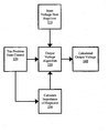
- Fig. 4 is a block diagram illustrating the flow of information to and from a control unit in a voltage regulator without an embedded potential transformer according to an embodiment of the present invention.
- FIG. 3 is a schematic illustration of the physical layout of an ANSI Type A voltage regulator without an potential transformer according to one embodiment of the present invention.
- the input, or source, voltage is measured between the S and SL bushings, or across the utility windings 310.
- the output, or load, voltage is calculated between the L and SL bushings.
- the windings and other internal components are mounted in an oil filled tank.
- the tap position changing mechanism is commonly sealed in the tank.
- the tap position changing mechanism is controlled by a control unit. In addition, the control unit keeps constant and accurate track of the current tap position.
- a block diagram illustrates the flow of information to and from a control unit in a voltage regulator without an embedded potential transformer according to one embodiment of the present invention.
- the control unit monitors the input voltage provided by the voltage regulator across the S and SL bushings, the tap position at all times, and the output voltage.
- the output voltage 240 is calculated from the output voltage algorithm 230 that uses the tap position supplied from the control unit 220, the input voltage across the voltage regulator utility windings 210, and from the calculated impedance of the voltage regulator itself 250.
- the output voltage algorithm may be stored on any computer-readable medium accessible to the control unit.
- the control unit will notify the tap position changing mechanism to change the tap position in response to the calculated output voltage in order to maintain a consistent output voltage across the L and SL bushings.
- the control unit considers each step, or each tap position, as a 5/8% difference in output.
- the control unit calculates an output voltage of the voltage regulator using a two step process.
- the control unit continuously monitors the tap changes as well as constantly stores the tap position electronically.
- the output voltage is approximated by the control unit by using the input voltage across the utility windings as well as the stored position of the tap.
- the output voltage value is calculated by taking the instantaneous input voltage from across the utility windings and multiplying it by one plus the physical tap position that has been multiplied by the voltage difference of one tap position (1).
- V out V in * 1 + tap_pos * V diff .1 tap pos .
- the voltage regulator is an electrical device, it also consumes power and places load on the electrical system. Therefore, the impedance of the voltage regulator must also be considered in the calculation of the output voltage by the control unit to ensure a more accurate output voltage value.
- the impedance of the voltage regulator is found from using the instantaneous current through the regulator, the maximum rated current of the voltage regulator, the instantaneous voltage through the voltage regulator, the instantaneous power factor, and the tap position of the voltage regulator.
- the calculated output voltage value can be summarized as equaling the output voltage value plus the voltage drop (2) due to the impedance of the voltage regulator.
- the resistive component of the instantaneous current value equals the instantaneous current value multiplied by the absolute value of the instantaneous power factor (4).
- the instantaneous power factor is derived from fundamental voltage and current frequencies and is represented by the ratio of real power to apparent power. If the instantaneous power factor is less that zero, then the power factor is leading and reactive component of the instantaneous current equals the instantaneous current multiplied by the square root of one minus the square of the power factor (5).
- the instantaneous power factor is greater than zero, the instantaneous power factor is lagging and the reactive component of the current equals the negative of the instantaneous current multiplied by the square root of one minus the square of the power factor (6).
- l react - l * sqrt ⁇ 1.0 - PF 2
- the impedance is then calculated to be 0.6% multiple by the square of the input voltage divided by the KVA rating of the voltage regulator (7).
- the KVA rating on voltage regulators defines the load carrying or power capability and stands for kilovolt-amperes. Since the KVA rating equals the input voltage multiplied by the maximum rated current (8), the impedance equation reduces to 0.6% times the input voltage divided by the maximum rated current (9) or 0.6% of the input voltage across that utility windings divided by maximum rated current (10).
- the impedance becomes 0.6% multiplied by the instantaneous input voltage across the utility windings divided by the maximum rated current multiplied by the tap position squared divided by sixteen squared (11).
- Z 0.006 * V 2 / KVA
- KVA V * l max
- Z 0.006 * V / l max
- Z 0.006 * V in / I max
- Z 0.006 * V in / l max * tap_ pos 2 / 16 2
- the resistive component of the impedance can be considered to equal one quarter the reactive impedance. Therefore, the reactive component of the impedance equals the calculated impedance or four times the resistive component of the impedance (12). Finally, the voltage drop is calculated to equal the resistive component of the impedance multiplied by the resistive component of the current minus the reactive component of the impedance multiplied by the reactive component of the current (13). The control unit can then use this value to determine accurately the output voltage in equation (2) and to notify the tap position changing mechanism when it is appropriate to change the position of the tap.
Landscapes
- Engineering & Computer Science (AREA)
- Power Engineering (AREA)
- Physics & Mathematics (AREA)
- Electromagnetism (AREA)
- General Physics & Mathematics (AREA)
- Radar, Positioning & Navigation (AREA)
- Automation & Control Theory (AREA)
- Control Of Electrical Variables (AREA)
- Ac-Ac Conversion (AREA)
- Supply And Distribution Of Alternating Current (AREA)
Abstract
Description
- The present invention relates to voltage regulators and, more particularly, to the use of the utility winding and a control unit in ANSI Type "A" Voltage Regulators to calculate the load voltage without the need of an embedded potential transformer.
- A voltage regulator can be thought of as an autotransformer that regulates a secondary voltage. If there is a primary voltage that has a tendency to fluctuate, a voltage regulator will produce a constant secondary voltage. For instance, if a primary , or input, voltage fluctuates between 110 volts and 130 volts, the voltage regulator will maintain the secondary, or output, voltage at a constant 120 volts. Usually, a voltage regulator can increase or decrease its output voltage by up to 10% of its input voltage in 5/8% steps. The voltage regulator is equipped with a control unit which monitors the input and output voltages of the voltage regulator and moves the tap changer by the 5/8% steps to maintain a specified output voltage.
- Typically, an ANSI load-side series winding, or Type "A," voltage regulator uses a separate potential transformer to sense the load voltage and feeds that voltage to the control unit so that the control unit can change the tap position as needed. Fig. 1 illustrates the typical physical connection of a
voltage regulator 100 with an embeddedpotential transformer 60. Thepotential transformer 60 is connected between the "L" and "SL" bushings. For example, the source voltage across the S and SL bushings may fluctuate between about 6900 volts and about 8300 volts. The load voltage is then stepped down by thepotential transformer 60 to approximately 120 volts (or roughly between about 110 volts to about 130 volts). The control unit (not shown) then changes the tap position in response to the stepped down source voltage which results in the output voltage across the L and SL bushings of a constant 7620 volts. - Fig. 2 illustrates a block diagram of the flow of information to the control unit in a typical embodiment of a voltage regulator that contains an embedded potential transformer. In
block 130, the voltage regulator feeds the input voltage to the control panel. In addition, instep 140, the output voltage from the embedded potential transformer supplies the output voltage to the control panel. The control panel, instep 150, in turn monitors the input and output voltages and adjusts position of the tap in order to adjust the output voltage as needed. - However, a need exists to simplify a voltage regulator by eliminating some of its components. By eliminating components of the voltage regulator, the material and manufacturing costs are reduced. In addition, the reliability of ANSI Type A voltage regulator increases with the reduction of components.
- United States patent
5,550,459 describes a voltage regulator controller which includes means for determining the tap position based on regulator impedance characteristics. The regulator tap position may be determined as a function of the regulator input voltage, the regulator output voltage, the regulator series winding (line) current, system load power factor and internal regulator impedance. - Aspects and embodiments of the invention are set out in the accompanying claims.
- According to the present invention, the utility windings and a control unit already present in voltage regulators will be used to sense the source voltage and calculate the load voltage in the voltage regulator without the need of a potential transformer. The utility windings provide the source, or input, voltage for the control unit. The control unit constantly monitors all tap changes as well as continuously stores the tap position electronically. The output voltage is calculated by the control unit by using the input voltage across the utility windings and the tap position in memory. To calculate a more accurate output voltage, the inherent impendence of the voltage regulator itself is considered in the calculation. The impedance of the voltage regulator is calculated using the instantaneous current through the regulator, the maximum rated current of the voltage regulator, the instantaneous voltage through the voltage regulator, the instantaneous power factor, and the tap position of the voltage regulator. The control unit, then in turn, may change the position of the tap in response to the load voltage.
- In accordance with one embodiment of the present invention, the control unit software will be adjusted and reprogrammed for different modes of applications.
- Accordingly, it is an object of the present invention to reduce the cost of material needed as well as the cost of manufacturing for the ANSI Type "A" voltage regulators by eliminating the need for the potential transformer component. By eliminating the potential transformer, reliability of the voltage regulator will increase due to the reduction of one active component in its assembly.
- Other objects of the present invention will be apparent in light of the description of the invention embodied herein.
- The following detailed description of specific embodiments of the present invention can be best understood when read in conjunction with the following drawings, where like structure is indicated with like reference numerals and in which:
- Fig. 1 is a schematic illustration of the typical physical layout of a voltage regulator with an embedded potential transformer;
- Fig. 2 is a block diagram of the flow of information to the control unit in a typical embodiment of a voltage regulator with an embedded potential transformer;
- Fig. 3 is a schematic illustration of the physical layout of a voltage regulator without an embedded potential transformer according to an embodiment of the present invention;
- Fig. 4 is a block diagram illustrating the flow of information to and from a control unit in a voltage regulator without an embedded potential transformer according to an embodiment of the present invention.
- In the following detailed description of the preferred embodiments, reference is made to the accompanying drawing that forms a part hereof, and in which is shown by way of illustration, and not by way of limitation, a specific embodiment in which the invention may be practiced. It is to be understood that other embodiments may be utilized and that logical, mechanical and electrical changes may be made without departing from the spirit and scope of the present invention.
- Referring to Fig. 3, is a schematic illustration of the physical layout of an ANSI Type A voltage regulator without an potential transformer according to one embodiment of the present invention. The input, or source, voltage is measured between the S and SL bushings, or across the
utility windings 310. The output, or load, voltage is calculated between the L and SL bushings. The windings and other internal components are mounted in an oil filled tank. The tap position changing mechanism is commonly sealed in the tank. The tap position changing mechanism is controlled by a control unit. In addition, the control unit keeps constant and accurate track of the current tap position. - Referring to Fig. 4, a block diagram illustrates the flow of information to and from a control unit in a voltage regulator without an embedded potential transformer according to one embodiment of the present invention. The control unit monitors the input voltage provided by the voltage regulator across the S and SL bushings, the tap position at all times, and the output voltage. The
output voltage 240 is calculated from theoutput voltage algorithm 230 that uses the tap position supplied from thecontrol unit 220, the input voltage across the voltageregulator utility windings 210, and from the calculated impedance of the voltage regulator itself 250. The output voltage algorithm may be stored on any computer-readable medium accessible to the control unit. The control unit will notify the tap position changing mechanism to change the tap position in response to the calculated output voltage in order to maintain a consistent output voltage across the L and SL bushings. The control unit considers each step, or each tap position, as a 5/8% difference in output. - The control unit calculates an output voltage of the voltage regulator using a two step process. First, the control unit continuously monitors the tap changes as well as constantly stores the tap position electronically. Second, the output voltage is approximated by the control unit by using the input voltage across the utility windings as well as the stored position of the tap. The output voltage value is calculated by taking the instantaneous input voltage from across the utility windings and multiplying it by one plus the physical tap position that has been multiplied by the voltage difference of one tap position (1).

- However, since the voltage regulator is an electrical device, it also consumes power and places load on the electrical system. Therefore, the impedance of the voltage regulator must also be considered in the calculation of the output voltage by the control unit to ensure a more accurate output voltage value. The impedance of the voltage regulator is found from using the instantaneous current through the regulator, the maximum rated current of the voltage regulator, the instantaneous voltage through the voltage regulator, the instantaneous power factor, and the tap position of the voltage regulator.
- The calculated output voltage value can be summarized as equaling the output voltage value plus the voltage drop (2) due to the impedance of the voltage regulator. The voltage drop equals the instantaneous current multiplied by the impedance of the voltage regulator (3). Both the instantaneous current and the impedance are complex numbers.


- The resistive component of the instantaneous current value equals the instantaneous current value multiplied by the absolute value of the instantaneous power factor (4). The instantaneous power factor is derived from fundamental voltage and current frequencies and is represented by the ratio of real power to apparent power. If the instantaneous power factor is less that zero, then the power factor is leading and reactive component of the instantaneous current equals the instantaneous current multiplied by the square root of one minus the square of the power factor (5). On the other hand, if the instantaneous power factor is greater than zero, the instantaneous power factor is lagging and the reactive component of the current equals the negative of the instantaneous current multiplied by the square root of one minus the square of the power factor (6).


- Assuming that the impedance percentage is known at a particular tap position, for example 0.6% at tap position 16, the impedance is then calculated to be 0.6% multiple by the square of the input voltage divided by the KVA rating of the voltage regulator (7). The KVA rating on voltage regulators defines the load carrying or power capability and stands for kilovolt-amperes. Since the KVA rating equals the input voltage multiplied by the maximum rated current (8), the impedance equation reduces to 0.6% times the input voltage divided by the maximum rated current (9) or 0.6% of the input voltage across that utility windings divided by maximum rated current (10). Therefore, to find the impedance at any tap position, the impedance becomes 0.6% multiplied by the instantaneous input voltage across the utility windings divided by the maximum rated current multiplied by the tap position squared divided by sixteen squared (11).


- Since the impedance is complex and mostly reactive, the resistive component of the impedance can be considered to equal one quarter the reactive impedance. Therefore, the reactive component of the impedance equals the calculated impedance or four times the resistive component of the impedance (12). Finally, the voltage drop is calculated to equal the resistive component of the impedance multiplied by the resistive component of the current minus the reactive component of the impedance multiplied by the reactive component of the current (13). The control unit can then use this value to determine accurately the output voltage in equation (2) and to notify the tap position changing mechanism when it is appropriate to change the position of the tap.


- It is noted that terms like "preferably," "commonly," and "typically" are not utilized herein to limit the scope of the claimed invention or to imply that certain features are critical, essential, or even important to the structure or function of the claimed invention. Rather, these terms are merely intended to highlight alternative or additional features that may or may not be utilized in a particular embodiment of the present invention.
Claims (27)
- A voltage regulator for regulating an output voltage (Vout) in response to an input voltage (Vin) the voltage regulator comprising:- at least three external bushings (S, L, SL) for accessing electrical signals and for allowing reading of the values of said input and output voltages of said voltage regulator;- a control unit for constant monitoring of input voltage and output voltage;- internal utility windings (310) for providing said input voltage and to power said control unit; and- a tap changing mechanism for manipulating a tap position (tap_pos) in response to a command received from said control unit, characterised in that- the output voltage is regulated also in response to a calculated output voltage (240); and in that- the control unit is further for constant monitoring of said tap position (220), for continuously storing said tap position (tap_pos) electronically, and for approximately calculating an output voltage, and refining said calculated output voltage (Vcal. out) by factoring in the effects of the impedance inherent to said voltage regulator.
- The voltage regulator of claim 1 wherein said calculation of output voltage (240) is calculated using said stored tap position (220) and the input voltage across said utility windings (310).
- The voltage regulator of claim 1 wherein said calculation of output voltage is calculated by said control unit.
- The voltage regulator of claim 3 wherein said calculation of output voltage is calculated by multiplying the input voltage across said utility windings (310) by one plus the tap position (tap_pos) multiplied by the voltage difference of one step (Vdiff. 1 tappos).
- The voltage regulator of claim 4 wherein each said step is a 5/8% difference in output voltage.
- The voltage regulator of claim 4 wherein said refining of said calculated output voltage (Vcal. out) comprises adding said output voltage (Vout) plus a voltage drop (Vdrop), wherein said voltage drop is the product of the instantaneous current (I) through said voltage regulator and the impedance (Z) of said voltage regulator.
- The voltage regulator of claim 6 wherein said voltage drop is determined by multiplying a resistive component of said impedance of said voltage regulator (Zres) and a resistive component of said instantaneous current (Ires) through said voltage regulator, minus the product of a reactive component of said impedance of said voltage regulator (Zreact) and a reactive component of said instantaneous current through said voltage regulator (Ireact).
- The voltage regulator of claim 6, wherein said instantaneous current and said impedance are complex numbers.
- The voltage regulator of claim 8, wherein said impedance is mostly reactive.
- The voltage regulator of claim 8, wherein the resistive component of the instantaneous current (Ires) equals the value of said instantaneous current (I) multiplied by the absolute value of the instantaneous power factor of said voltage regulator (1PFl).
- The voltage regulator of claim 10, wherein said instantaneous power factor is represented by the ratio of real power to apparent power of said voltage regulator.
- The voltage regulator of claim 10, wherein said instantaneous power factor is leading if said instantaneous power factor is less than zero.
- The voltage regulator of claim 12, wherein if said instantaneous power factor is leading, the reactive component of said instantaneous current (Ireact) equals said instantaneous current (I) multiplied by the square root of a number obtained by deducting from unity the square of said instantaneous power factor (PF).
- The voltage regulator of claim 10, wherein said instantaneous power factor is lagging if said instantaneous power factor is greater than zero.
- The voltage regulator of claim 14, wherein if said instantaneous power factor is lagging, the reactive component of said instantaneous current (Ireact) equals the negative of said instantaneous current (I) multiplied by the square root of a number obtained by deducting from unity the square of said instantaneous power factor (PF).
- The voltage regulator of claim 1 wherein said refining of said calculated output voltage is achieved by calculations using the tap position (tap_pos), the voltage across said utility windings (Vin), and the impedance (Z) of said voltage regulator.
- The voltage regulator of claim 16, wherein said impedance (Z) of said voltage regulator is calculated using instantaneous current (I) through said voltage regulator, maximum rated current (Imax) of said voltage regulator, instantaneous voltage across said voltage regulator (Vin), instantaneous power factor (PF) and said tap position of said voltage regulator (tap_pos).
- The voltage regulator of claim 17, wherein resistive component of said impedance of said voltage regulator equals 0.25 multiplied by input voltage (S-SL) across said utility windings (310) divided by said maximum rated current of said voltage regulator (Imax) multiplied by a known percentage of impedance at a known tap position multiplied by the square of said monitored tap position (tap_pos), whose product is divided by the square of said known tap position.
- The voltage regulator of claim 17, wherein reactive component of said impedance (Zreact) of said voltage regulator equals four times said resistive component of said impedance of said voltage regulator.
- The voltage regulator of claim 1 wherein said control unit notifies said tap changing mechanism to change tap position in response to said calculation of output voltage (240).
- A method of calculating an output voltage (Vout) in a voltage regulator, the method comprising:- determining the input voltage (Vin) across internal utility windings (310) of said voltage regulator;- monitoring constantly said input voltage, tap position (tap_pos) and output voltage by a control unit;- storing continuously said tap position electronically by said control unit (220);- approximately calculating an output voltage (Vcal. out) using said tap position and said input voltage by said control unit; refining said calculated output voltage by said control unit by factoring in the effects of the impedance (Z) inherent to said voltage regulator; and changing position of said tap in response to said refined calculated output voltage determined by said control unit.
- The method of calculating the output voltage of claim 21, wherein the calculated output voltage is calculated by multiplying said input voltage by the sum of unity and a number obtained by multiplying the tap position by the voltage difference of one tap position (Vdiff. 1 tappos).
- The method of calculating the output voltage of claim 21, wherein determining accurately said calculated output voltage involves adding the voltage drop (Vdrop) to said output voltage (Vout), wherein said voltage drop is the product of the instantaneous current (I) through said voltage regulator and the impedance (Z) of said voltage regulator.
- The method of calculating the output voltage of claim 23, further comprising:calculating said voltage drop, wherein real component of said voltage drop equals:- the product of a resistive component of said impedance of said voltage regulator (Zres) and a resistive component of said instantaneous current through said voltage regulator (Ires), minus- the product of a reactive component of said impedance of said voltage regulator (Zreact) and a reactive component of said instantaneous current through said voltage regulator (Ireact).
- The method of calculating the output voltage of claim 21, further comprising:calculating said impedance (Z) of said voltage regulator, wherein said impedance is a complex number and the reactive component of said impedance of said voltage regulator (Zreact) equals four times the resistive component of said impedance of said voltage regulator.
- The method of calculating the output voltage of claim 25, wherein the resistive component of said impedance of said voltage regulator equals 0.25 multiplied by said input voltage (Vin) divided by said maximum rated current of said voltage regulator (Imax) multiplied by a known percentage of impedance at a known tap position multiplied by the square of said monitored tap position (tap_pos) whose product is divided by the square of said known tap position.
- A computer-readable medium having stored thereon computer-executable instructions for calculating an output voltage (Vout) in a voltage regulator, the computer executable instructions when executed by a processor, cause the processor to perform a method comprising the steps of:- determining the input voltage (Vin) across internal utility windings (310) of said voltage regulator;- monitoring constantly said input voltage, tap position (tap_pos) and output voltage (Vout) by a control unit;- storing continuously said tap position electronically by said control unit (220);- approximately calculating an output voltage (Vout) using said tap position and said input voltage by said control unit;- refining said calculated output voltage (Vcal. out) by said control unit by factoring in the effects of an impedance (Z) inherent to said voltage regulator; and- changing position of said tap in response to said refined calculated output voltage determined by said control unit.
Applications Claiming Priority (2)
| Application Number | Priority Date | Filing Date | Title |
|---|---|---|---|
| US48041303P | 2003-06-20 | 2003-06-20 | |
| PCT/US2004/019705 WO2004114041A1 (en) | 2003-06-20 | 2004-06-21 | Regulated tap transformer |
Publications (2)
| Publication Number | Publication Date |
|---|---|
| EP1636659A1 EP1636659A1 (en) | 2006-03-22 |
| EP1636659B1 true EP1636659B1 (en) | 2012-02-29 |
Family
ID=33539294
Family Applications (1)
| Application Number | Title | Priority Date | Filing Date |
|---|---|---|---|
| EP04755709A Expired - Lifetime EP1636659B1 (en) | 2003-06-20 | 2004-06-21 | Regulated tap transformer |
Country Status (5)
| Country | Link |
|---|---|
| US (1) | US7023193B2 (en) |
| EP (1) | EP1636659B1 (en) |
| JP (1) | JP4350749B2 (en) |
| AT (1) | ATE547751T1 (en) |
| WO (1) | WO2004114041A1 (en) |
Families Citing this family (6)
| Publication number | Priority date | Publication date | Assignee | Title |
|---|---|---|---|---|
| US6805791B2 (en) * | 2000-09-01 | 2004-10-19 | Applied Science And Technology, Inc. | Ozonated water flow and concentration control apparatus |
| US8519681B2 (en) | 2011-02-11 | 2013-08-27 | Siemens Energy, Inc. | Apparatus and method for generating a metering voltage output for a voltage regulator using a microprocessor |
| US20130154607A1 (en) * | 2011-12-20 | 2013-06-20 | Itb Equipamentos Eletricos Ltda | Reactive regulator |
| GB2514296B (en) | 2012-03-01 | 2020-02-19 | Eaton Intelligent Power Ltd | Managed Multi-phase Operation |
| ES2941248T3 (en) * | 2016-12-19 | 2023-05-19 | Hitachi Energy Switzerland Ag | Longitudinal tension regulator |
| TWI894694B (en) * | 2023-11-21 | 2025-08-21 | 華城電機股份有限公司 | Monitoring management system of transformers |
Family Cites Families (8)
| Publication number | Priority date | Publication date | Assignee | Title |
|---|---|---|---|---|
| GB833255A (en) | 1955-10-28 | 1960-04-21 | Gen Electric | Improvements relating to electric supply systems |
| GB1086147A (en) | 1965-02-19 | 1967-10-04 | Gen Electric Co Ltd | Improvements in or relating to electrical control arrangements |
| US4307345A (en) | 1979-11-26 | 1981-12-22 | E.I.L. Instruments, Inc. | Circuit recloser test set |
| US4336490A (en) * | 1981-01-28 | 1982-06-22 | Mcgraw-Edison Company | Voltage sensing apparatus for a voltage regulating transformer |
| US4896092A (en) * | 1988-10-12 | 1990-01-23 | Power Distribution, Inc. | Voltage regulator for AC single phase and three phase systems |
| US5550459A (en) * | 1994-08-08 | 1996-08-27 | Siemens Energy & Automation, Inc. | Tap position determination based on regular impedance characteristics |
| US5619121A (en) * | 1995-06-29 | 1997-04-08 | Siemens Energy & Automation, Inc. | Load voltage based tap changer monitoring system |
| US5633580A (en) * | 1995-06-29 | 1997-05-27 | Siemens Energy & Automation, Inc. | Direct load current sensing for predicted regulator tap position |
-
2004
- 2004-06-21 EP EP04755709A patent/EP1636659B1/en not_active Expired - Lifetime
- 2004-06-21 US US10/872,732 patent/US7023193B2/en not_active Expired - Lifetime
- 2004-06-21 AT AT04755709T patent/ATE547751T1/en active
- 2004-06-21 JP JP2006517468A patent/JP4350749B2/en not_active Expired - Lifetime
- 2004-06-21 WO PCT/US2004/019705 patent/WO2004114041A1/en not_active Ceased
Also Published As
| Publication number | Publication date |
|---|---|
| WO2004114041A1 (en) | 2004-12-29 |
| US20050007079A1 (en) | 2005-01-13 |
| EP1636659A1 (en) | 2006-03-22 |
| ATE547751T1 (en) | 2012-03-15 |
| JP2007525136A (en) | 2007-08-30 |
| JP4350749B2 (en) | 2009-10-21 |
| US7023193B2 (en) | 2006-04-04 |
Similar Documents
| Publication | Publication Date | Title |
|---|---|---|
| AU2015298737B2 (en) | Voltage regulator for a power distribution system and method of controlling same | |
| US20220253080A1 (en) | Smart voltage reduction and reverse power operating mode determination for load tap charging transformers and voltage regulators | |
| US5900723A (en) | Voltage based VAR compensation system | |
| US4262242A (en) | Voltage regulator | |
| EP1324459B1 (en) | Reactive power compensator | |
| AU2009338258A1 (en) | Automatic voltage regulator and toroidal transformer | |
| EP3059829B1 (en) | System and method for regulating energy in electrical installations | |
| US10177672B2 (en) | Voltage regulation for multi-phase power systems | |
| US7023193B2 (en) | Elimination of potential transformer in ANSI Type A voltage regulator | |
| JP6877295B2 (en) | Judgment method of voltage regulator and voltage regulator | |
| US11404868B2 (en) | Over-voltage prevention apparatus and method of distribution line connected with distributed generator | |
| JPH0578250B2 (en) | ||
| JPH11231949A (en) | Voltage adjusting device | |
| KR20190043297A (en) | Apparatus for controlling voltage regulation based on voltage measurement, Method thereof, and Computer readable storage medium having the same | |
| JP2631547B2 (en) | Substation bus voltage control method | |
| JP2018180574A (en) | Control device and power conversion system | |
| KR200352461Y1 (en) | Device for saving electricity added automatic power factor control function | |
| JPH10290528A (en) | Voltage reactive power monitoring and control device | |
| KR102704665B1 (en) | Apparatus for compensating lead power factor of transformer | |
| JP2000069668A (en) | High voltage automatic voltage regulator setting parameter analyzer | |
| SU736262A1 (en) | Method of control of dc transmission mode | |
| JPH03257512A (en) | Automatic power factor adjusting device | |
| Li et al. | Quantative methods for DC-DC converter performance analysis in distributed power systems | |
| KR20220012101A (en) | Apparatus and method for voltage control of distribution line in which distributed power is introduced | |
| KR20230046589A (en) | Apparatus and method for controlling tab-changer transformer |
Legal Events
| Date | Code | Title | Description |
|---|---|---|---|
| PUAI | Public reference made under article 153(3) epc to a published international application that has entered the european phase |
Free format text: ORIGINAL CODE: 0009012 |
|
| 17P | Request for examination filed |
Effective date: 20051213 |
|
| AK | Designated contracting states |
Kind code of ref document: A1 Designated state(s): AT BE BG CH CY CZ DE DK EE ES FI FR GB GR HU IE IT LI LU MC NL PL PT RO SE SI SK TR |
|
| RIN1 | Information on inventor provided before grant (corrected) |
Inventor name: SOHAIL, MUHAMMAD Inventor name: CHAMPION, ROBERT |
|
| DAX | Request for extension of the european patent (deleted) | ||
| 17Q | First examination report despatched |
Effective date: 20070305 |
|
| RAP1 | Party data changed (applicant data changed or rights of an application transferred) |
Owner name: SIEMENS ENERGY, INC. |
|
| GRAP | Despatch of communication of intention to grant a patent |
Free format text: ORIGINAL CODE: EPIDOSNIGR1 |
|
| GRAS | Grant fee paid |
Free format text: ORIGINAL CODE: EPIDOSNIGR3 |
|
| GRAA | (expected) grant |
Free format text: ORIGINAL CODE: 0009210 |
|
| AK | Designated contracting states |
Kind code of ref document: B1 Designated state(s): AT BE BG CH CY CZ DE DK EE ES FI FR GB GR HU IE IT LI LU MC NL PL PT RO SE SI SK TR |
|
| REG | Reference to a national code |
Ref country code: GB Ref legal event code: FG4D Ref country code: CH Ref legal event code: EP |
|
| REG | Reference to a national code |
Ref country code: AT Ref legal event code: REF Ref document number: 547751 Country of ref document: AT Kind code of ref document: T Effective date: 20120315 |
|
| REG | Reference to a national code |
Ref country code: IE Ref legal event code: FG4D |
|
| REG | Reference to a national code |
Ref country code: DE Ref legal event code: R096 Ref document number: 602004036717 Country of ref document: DE Effective date: 20120426 |
|
| REG | Reference to a national code |
Ref country code: GR Ref legal event code: EP Ref document number: 20120400806 Country of ref document: GR Effective date: 20120518 |
|
| REG | Reference to a national code |
Ref country code: NL Ref legal event code: VDEP Effective date: 20120229 |
|
| PG25 | Lapsed in a contracting state [announced via postgrant information from national office to epo] |
Ref country code: NL Free format text: LAPSE BECAUSE OF FAILURE TO SUBMIT A TRANSLATION OF THE DESCRIPTION OR TO PAY THE FEE WITHIN THE PRESCRIBED TIME-LIMIT Effective date: 20120229 |
|
| PG25 | Lapsed in a contracting state [announced via postgrant information from national office to epo] |
Ref country code: PT Free format text: LAPSE BECAUSE OF FAILURE TO SUBMIT A TRANSLATION OF THE DESCRIPTION OR TO PAY THE FEE WITHIN THE PRESCRIBED TIME-LIMIT Effective date: 20120629 Ref country code: FI Free format text: LAPSE BECAUSE OF FAILURE TO SUBMIT A TRANSLATION OF THE DESCRIPTION OR TO PAY THE FEE WITHIN THE PRESCRIBED TIME-LIMIT Effective date: 20120229 Ref country code: BE Free format text: LAPSE BECAUSE OF FAILURE TO SUBMIT A TRANSLATION OF THE DESCRIPTION OR TO PAY THE FEE WITHIN THE PRESCRIBED TIME-LIMIT Effective date: 20120229 |
|
| REG | Reference to a national code |
Ref country code: AT Ref legal event code: MK05 Ref document number: 547751 Country of ref document: AT Kind code of ref document: T Effective date: 20120229 |
|
| PG25 | Lapsed in a contracting state [announced via postgrant information from national office to epo] |
Ref country code: CY Free format text: LAPSE BECAUSE OF FAILURE TO SUBMIT A TRANSLATION OF THE DESCRIPTION OR TO PAY THE FEE WITHIN THE PRESCRIBED TIME-LIMIT Effective date: 20120229 |
|
| PG25 | Lapsed in a contracting state [announced via postgrant information from national office to epo] |
Ref country code: DK Free format text: LAPSE BECAUSE OF FAILURE TO SUBMIT A TRANSLATION OF THE DESCRIPTION OR TO PAY THE FEE WITHIN THE PRESCRIBED TIME-LIMIT Effective date: 20120229 Ref country code: SI Free format text: LAPSE BECAUSE OF FAILURE TO SUBMIT A TRANSLATION OF THE DESCRIPTION OR TO PAY THE FEE WITHIN THE PRESCRIBED TIME-LIMIT Effective date: 20120229 Ref country code: SE Free format text: LAPSE BECAUSE OF FAILURE TO SUBMIT A TRANSLATION OF THE DESCRIPTION OR TO PAY THE FEE WITHIN THE PRESCRIBED TIME-LIMIT Effective date: 20120229 Ref country code: RO Free format text: LAPSE BECAUSE OF FAILURE TO SUBMIT A TRANSLATION OF THE DESCRIPTION OR TO PAY THE FEE WITHIN THE PRESCRIBED TIME-LIMIT Effective date: 20120229 Ref country code: CZ Free format text: LAPSE BECAUSE OF FAILURE TO SUBMIT A TRANSLATION OF THE DESCRIPTION OR TO PAY THE FEE WITHIN THE PRESCRIBED TIME-LIMIT Effective date: 20120229 Ref country code: EE Free format text: LAPSE BECAUSE OF FAILURE TO SUBMIT A TRANSLATION OF THE DESCRIPTION OR TO PAY THE FEE WITHIN THE PRESCRIBED TIME-LIMIT Effective date: 20120229 Ref country code: PL Free format text: LAPSE BECAUSE OF FAILURE TO SUBMIT A TRANSLATION OF THE DESCRIPTION OR TO PAY THE FEE WITHIN THE PRESCRIBED TIME-LIMIT Effective date: 20120229 |
|
| PG25 | Lapsed in a contracting state [announced via postgrant information from national office to epo] |
Ref country code: SK Free format text: LAPSE BECAUSE OF FAILURE TO SUBMIT A TRANSLATION OF THE DESCRIPTION OR TO PAY THE FEE WITHIN THE PRESCRIBED TIME-LIMIT Effective date: 20120229 Ref country code: IT Free format text: LAPSE BECAUSE OF FAILURE TO SUBMIT A TRANSLATION OF THE DESCRIPTION OR TO PAY THE FEE WITHIN THE PRESCRIBED TIME-LIMIT Effective date: 20120229 |
|
| PLBE | No opposition filed within time limit |
Free format text: ORIGINAL CODE: 0009261 |
|
| STAA | Information on the status of an ep patent application or granted ep patent |
Free format text: STATUS: NO OPPOSITION FILED WITHIN TIME LIMIT |
|
| PG25 | Lapsed in a contracting state [announced via postgrant information from national office to epo] |
Ref country code: MC Free format text: LAPSE BECAUSE OF NON-PAYMENT OF DUE FEES Effective date: 20120630 Ref country code: AT Free format text: LAPSE BECAUSE OF FAILURE TO SUBMIT A TRANSLATION OF THE DESCRIPTION OR TO PAY THE FEE WITHIN THE PRESCRIBED TIME-LIMIT Effective date: 20120229 |
|
| REG | Reference to a national code |
Ref country code: CH Ref legal event code: PL |
|
| 26N | No opposition filed |
Effective date: 20121130 |
|
| REG | Reference to a national code |
Ref country code: CH Ref legal event code: PL |
|
| GBPC | Gb: european patent ceased through non-payment of renewal fee |
Effective date: 20120621 |
|
| REG | Reference to a national code |
Ref country code: IE Ref legal event code: MM4A |
|
| REG | Reference to a national code |
Ref country code: DE Ref legal event code: R097 Ref document number: 602004036717 Country of ref document: DE Effective date: 20121130 |
|
| REG | Reference to a national code |
Ref country code: FR Ref legal event code: ST Effective date: 20130228 |
|
| REG | Reference to a national code |
Ref country code: DE Ref legal event code: R119 Ref document number: 602004036717 Country of ref document: DE Effective date: 20130101 |
|
| PG25 | Lapsed in a contracting state [announced via postgrant information from national office to epo] |
Ref country code: FR Free format text: LAPSE BECAUSE OF NON-PAYMENT OF DUE FEES Effective date: 20120702 Ref country code: LI Free format text: LAPSE BECAUSE OF NON-PAYMENT OF DUE FEES Effective date: 20120630 Ref country code: CH Free format text: LAPSE BECAUSE OF NON-PAYMENT OF DUE FEES Effective date: 20120630 Ref country code: GB Free format text: LAPSE BECAUSE OF NON-PAYMENT OF DUE FEES Effective date: 20120621 Ref country code: DE Free format text: LAPSE BECAUSE OF NON-PAYMENT OF DUE FEES Effective date: 20130101 Ref country code: ES Free format text: LAPSE BECAUSE OF FAILURE TO SUBMIT A TRANSLATION OF THE DESCRIPTION OR TO PAY THE FEE WITHIN THE PRESCRIBED TIME-LIMIT Effective date: 20120609 Ref country code: IE Free format text: LAPSE BECAUSE OF NON-PAYMENT OF DUE FEES Effective date: 20120621 |
|
| PG25 | Lapsed in a contracting state [announced via postgrant information from national office to epo] |
Ref country code: BG Free format text: LAPSE BECAUSE OF FAILURE TO SUBMIT A TRANSLATION OF THE DESCRIPTION OR TO PAY THE FEE WITHIN THE PRESCRIBED TIME-LIMIT Effective date: 20120529 |
|
| PG25 | Lapsed in a contracting state [announced via postgrant information from national office to epo] |
Ref country code: TR Free format text: LAPSE BECAUSE OF FAILURE TO SUBMIT A TRANSLATION OF THE DESCRIPTION OR TO PAY THE FEE WITHIN THE PRESCRIBED TIME-LIMIT Effective date: 20120229 |
|
| PG25 | Lapsed in a contracting state [announced via postgrant information from national office to epo] |
Ref country code: LU Free format text: LAPSE BECAUSE OF NON-PAYMENT OF DUE FEES Effective date: 20120621 |
|
| PG25 | Lapsed in a contracting state [announced via postgrant information from national office to epo] |
Ref country code: HU Free format text: LAPSE BECAUSE OF FAILURE TO SUBMIT A TRANSLATION OF THE DESCRIPTION OR TO PAY THE FEE WITHIN THE PRESCRIBED TIME-LIMIT Effective date: 20040621 |
|
| PGFP | Annual fee paid to national office [announced via postgrant information from national office to epo] |
Ref country code: GR Payment date: 20230620 Year of fee payment: 20 |