EP1635423A2 - Method and structure for waterproofing a terminal splice - Google Patents
Method and structure for waterproofing a terminal splice Download PDFInfo
- Publication number
- EP1635423A2 EP1635423A2 EP05019258A EP05019258A EP1635423A2 EP 1635423 A2 EP1635423 A2 EP 1635423A2 EP 05019258 A EP05019258 A EP 05019258A EP 05019258 A EP05019258 A EP 05019258A EP 1635423 A2 EP1635423 A2 EP 1635423A2
- Authority
- EP
- European Patent Office
- Prior art keywords
- cap
- heat
- terminal splice
- waterproofing
- opening
- Prior art date
- Legal status (The legal status is an assumption and is not a legal conclusion. Google has not performed a legal analysis and makes no representation as to the accuracy of the status listed.)
- Granted
Links
Images


Classifications
-
- H—ELECTRICITY
- H01—ELECTRIC ELEMENTS
- H01R—ELECTRICALLY-CONDUCTIVE CONNECTIONS; STRUCTURAL ASSOCIATIONS OF A PLURALITY OF MUTUALLY-INSULATED ELECTRICAL CONNECTING ELEMENTS; COUPLING DEVICES; CURRENT COLLECTORS
- H01R43/00—Apparatus or processes specially adapted for manufacturing, assembling, maintaining, or repairing of line connectors or current collectors or for joining electric conductors
- H01R43/005—Apparatus or processes specially adapted for manufacturing, assembling, maintaining, or repairing of line connectors or current collectors or for joining electric conductors for making dustproof, splashproof, drip-proof, waterproof, or flameproof connection, coupling, or casing
-
- H—ELECTRICITY
- H01—ELECTRIC ELEMENTS
- H01R—ELECTRICALLY-CONDUCTIVE CONNECTIONS; STRUCTURAL ASSOCIATIONS OF A PLURALITY OF MUTUALLY-INSULATED ELECTRICAL CONNECTING ELEMENTS; COUPLING DEVICES; CURRENT COLLECTORS
- H01R13/00—Details of coupling devices of the kinds covered by groups H01R12/70 or H01R24/00 - H01R33/00
- H01R13/46—Bases; Cases
- H01R13/52—Dustproof, splashproof, drip-proof, waterproof, or flameproof cases
-
- H—ELECTRICITY
- H01—ELECTRIC ELEMENTS
- H01R—ELECTRICALLY-CONDUCTIVE CONNECTIONS; STRUCTURAL ASSOCIATIONS OF A PLURALITY OF MUTUALLY-INSULATED ELECTRICAL CONNECTING ELEMENTS; COUPLING DEVICES; CURRENT COLLECTORS
- H01R4/00—Electrically-conductive connections between two or more conductive members in direct contact, i.e. touching one another; Means for effecting or maintaining such contact; Electrically-conductive connections having two or more spaced connecting locations for conductors and using contact members penetrating insulation
- H01R4/22—End caps, i.e. of insulating or conductive material for covering or maintaining connections between wires entering the cap from the same end
-
- H—ELECTRICITY
- H01—ELECTRIC ELEMENTS
- H01R—ELECTRICALLY-CONDUCTIVE CONNECTIONS; STRUCTURAL ASSOCIATIONS OF A PLURALITY OF MUTUALLY-INSULATED ELECTRICAL CONNECTING ELEMENTS; COUPLING DEVICES; CURRENT COLLECTORS
- H01R4/00—Electrically-conductive connections between two or more conductive members in direct contact, i.e. touching one another; Means for effecting or maintaining such contact; Electrically-conductive connections having two or more spaced connecting locations for conductors and using contact members penetrating insulation
- H01R4/70—Insulation of connections
- H01R4/72—Insulation of connections using a heat shrinking insulating sleeve
-
- H—ELECTRICITY
- H02—GENERATION; CONVERSION OR DISTRIBUTION OF ELECTRIC POWER
- H02G—INSTALLATION OF ELECTRIC CABLES OR LINES, OR OF COMBINED OPTICAL AND ELECTRIC CABLES OR LINES
- H02G15/00—Cable fittings
- H02G15/02—Cable terminations
- H02G15/04—Cable-end sealings
- H02G15/043—Cable-end sealings with end caps, e.g. sleeve closed at one end
-
- H—ELECTRICITY
- H02—GENERATION; CONVERSION OR DISTRIBUTION OF ELECTRIC POWER
- H02G—INSTALLATION OF ELECTRIC CABLES OR LINES, OR OF COMBINED OPTICAL AND ELECTRIC CABLES OR LINES
- H02G15/00—Cable fittings
- H02G15/08—Cable junctions
- H02G15/18—Cable junctions protected by sleeves, e.g. for communication cable
- H02G15/1806—Heat shrinkable sleeves
-
- H—ELECTRICITY
- H01—ELECTRIC ELEMENTS
- H01R—ELECTRICALLY-CONDUCTIVE CONNECTIONS; STRUCTURAL ASSOCIATIONS OF A PLURALITY OF MUTUALLY-INSULATED ELECTRICAL CONNECTING ELEMENTS; COUPLING DEVICES; CURRENT COLLECTORS
- H01R13/00—Details of coupling devices of the kinds covered by groups H01R12/70 or H01R24/00 - H01R33/00
- H01R13/46—Bases; Cases
- H01R13/52—Dustproof, splashproof, drip-proof, waterproof, or flameproof cases
- H01R13/5216—Dustproof, splashproof, drip-proof, waterproof, or flameproof cases characterised by the sealing material, e.g. gels or resins
-
- H—ELECTRICITY
- H01—ELECTRIC ELEMENTS
- H01R—ELECTRICALLY-CONDUCTIVE CONNECTIONS; STRUCTURAL ASSOCIATIONS OF A PLURALITY OF MUTUALLY-INSULATED ELECTRICAL CONNECTING ELEMENTS; COUPLING DEVICES; CURRENT COLLECTORS
- H01R13/00—Details of coupling devices of the kinds covered by groups H01R12/70 or H01R24/00 - H01R33/00
- H01R13/46—Bases; Cases
- H01R13/52—Dustproof, splashproof, drip-proof, waterproof, or flameproof cases
- H01R13/5219—Sealing means between coupling parts, e.g. interfacial seal
- H01R13/5221—Sealing means between coupling parts, e.g. interfacial seal having cable sealing means
-
- H—ELECTRICITY
- H01—ELECTRIC ELEMENTS
- H01R—ELECTRICALLY-CONDUCTIVE CONNECTIONS; STRUCTURAL ASSOCIATIONS OF A PLURALITY OF MUTUALLY-INSULATED ELECTRICAL CONNECTING ELEMENTS; COUPLING DEVICES; CURRENT COLLECTORS
- H01R4/00—Electrically-conductive connections between two or more conductive members in direct contact, i.e. touching one another; Means for effecting or maintaining such contact; Electrically-conductive connections having two or more spaced connecting locations for conductors and using contact members penetrating insulation
- H01R4/02—Soldered or welded connections
- H01R4/029—Welded connections
Definitions
- the present invention relates to a method and a structure for waterproofing a terminal splice, and in particular for waterproofing the terminal splice at a location where strands stripped from a plurality of wire terminals are connected.
- a conventional method to electrically connect wires of a wire harness routed in an automobile is, as shown in Fig. 6, to weld and join strands Wa stripped from a plurality of wire W terminals to form a terminal splice Y. Waterproofing is required when terminal splice Y is placed in an area exposed to water as the wire harness is installed in a vehicle.
- Fig. 6 illustrates a conventional waterproofing method. In the conventional method, a specified amount of waterproofing agent 2 is injected into cap 1 from an injector (not shown in the figure) and terminal splice Y of each wire W is inserted into cap 1. Then, waterproofing agent 2 is hardened to seal terminal splice Y.
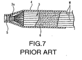
- Japanese Patent Laid-open Publication Hei 10-108345 provides a waterproofing method that tight-seals wire connection 3 as shown in Fig. 7.
- wire connection 3 having crimped part 3a, where a plurality of wire W strands are connected, is covered with heat shrinkable tube 4 having one end sealed by hotmelt 5.
- Butyl rubber 6 is injected inside heat shrinkable tube 4, which is then heat-treated to shrink the tube and to lower viscosity of butyl rubber 6 and spread the substance.
- butyl rubber 6 of low fluidity as filler reduces workability when injecting butyl rubber 6 inside heat shrinkable tube 4.
- waterproof performance may decline when butyl rubber 6 does not fill every gap between wires W and with heat shrinkable tube 4, depending on the location of butyl rubber 6 in heat shrinkable tube 4 or the heat level.
- the present invention is provided to address at least the above noted shortcomings, to reduce the diameter of a cap necessary to cover a terminal splice and to improve workability and waterproof performance.
- An aspect of the present invention provides a method of waterproofing a terminal splice including providing a heat shrinkable tube, the heat shrinkable tube having a first opening and a second opening; inserting a stopper in the first opening of the heat shrinkable tube; heat-shrinking the heat shrinkable tube having the stopper inserted therein, forming a cap having an end closure; injecting a fluid waterproofing agent into the cap through the second opening; inserting a terminal splice through the second opening of the cap and immersing the terminal splice in the waterproofing agent; and heating the cap at a predetermined temperature to heat-shrink the heat shrinkable tube and to accelerate hardening of the waterproofing agent.
- heating the cap comprises heating the entirety of the cap; and the terminal splice includes welded strands of wire stripped from a plurality of wire terminals. Additionally, the first opening includes a first open end and the second opening includes a second open end. Further, heating the cap includes heating the entirety of the cap, and heating the entire cap one time completes shrinkage of the heat shrinkable tube and hardens the waterproofing agent. Additionally, the waterproofing agent includes a two-liquid mixed type epoxy; and the stopper is formed of the same material as that for the heat shrinkable tube.
- a further aspect of the present invention provides a waterproof terminal splice including a heat-shrunk tube having a first opening and a second opening; a cap having an end closure provided on the heat-shrunk tube, the cap including a stopper inserted in the first opening of the heat-shrunk tube; a waterproofing agent provided in an interior space of the heat-shrunk tube; and a terminal splice provided in the interior space of the heat-shrunk tube, the terminal splice immersed in the waterproofing agent.
- the waterproof agent is a cured fluid.
- the cap is heated at a predetermined temperature to heat-shrink the tube and to accelerate hardening of the fluid into the waterproofing agent.
- the fluid is injected into the cap through the second opening and the cap is heated at a predetermined temperature to heat-shrink the tube and to accelerate hardening of the fluid into the waterproofing agent.
- the stopper is inserted in the tube through the first opening and the tube is heated to heat-shrink the tube, forming a cap having an end closure.
- the terminal splice may include welded strands of wire stripped from a plurality of wire terminals; and the first opening includes a first open end and the second opening includes a second open end.
- the method of the present invention using the heat shrinkable tube as a cap, allows the cap to fit the terminal splice through heat-shrinkage by the heat and minimizes an external diameter of the heat shrinkable tube after heating. Accordingly, the method allows downsizing of an external part of the terminal splice and minimizes usage of the waterproof agent to be injected, enabling cost reduction. Furthermore, the compact cap that covers the terminal splice improves the appearance of the waterproof terminal splice.
- An internal diameter of the heat shrinkable tube before heating can be large, improving workability as it is easy to inject the waterproofing agent into the cap.
- the molten waterproof agent has a high fluidity, which allows easier insertion into the cap and ensures that the agent spreads to every gap between wires and with the heat shrinkable tube, thus improves waterproof performance.
- heating and heat-shrinking the heat shrinkable tube accelerates hardening of the waterproofing agent at the same time, curbing increase in process time and steps. Heat-shrinking one opening of the heat shrinkable tube, while the stopper is inserted in the other opening of the tube, firmly attaches the stopper to the opening, thus improves air tightness at the end closure.
- the fluid waterproofing agent before hardening has a low viscosity of 50 Pa•s.
- thermosetting waterproofing agent which is a liquid at an ambient temperature, as the waterproofing agent, instead of a thermosetting waterproofing agent that starts hardening when two liquids are mixed and accelerates hardening when heated.
- the present invention also provides a waterproof structure for the terminal splice formed in the method of the present invention.
- the present invention employing the heat shrinkable tube to reduce the size of the cap after heating, reduces the size of an external part of the terminal splice and reduces usage of the waterproofing agent, contributing to cost reduction. Furthermore, high fluidity of the liquid waterproofing agent before heating improves workability when injecting the agent into the cap and waterproofing performance.
- Figs. 1, 2, 3, 4 and 5 illustrate procedures of the method that waterproof a terminal splice according to the embodiment of the present invention.
- heat shrinkable tube 11 has a first, slightly heat-shrunk opening 11a at a lower end and a second opening 11b at an upper end. Stopper 12 is inserted and located in opening 11a and the lower end of heat shrinkable tube 11 is heated while stopper 12 is positioned inside the opening 11a. Heating is indicated by the arrows in Fig. 1. Then, as shown in Fig. 2, the lower end of heat shrinkable tube 11 further heat-shrinks and stopper 12 melts and adheres to opening 11a, forming cap 10 having end closure 11c. Stopper 12 may be formed of the same material as used for heat shrinkable tube 11. Heat shrinkable tube 11 uses Sumitomo Electric Fine Polymer Sumitube®.
- thermosetting waterproofing agent 13 is injected into cap 10 through second opening 11b.
- an appropriate amount of a two-liquid mixed type epoxy solution as thermosetting waterproofing agent 13 is injected from first dispenser 14.
- an appropriate amount of a curing agent is injected from second dispenser 15. Taking into consideration the size, including and in particular the internal volume, that the heat shrinkable tube will be after heat shrinkage, a predetermined amount of thermosetting waterproofing agent 13 is injected, leaving space S having second opening 11b.
- thermosetting waterproofing agent 13 that is, a connection of welded strands Wa stripped from terminals of a plurality of wires W, is inserted through second opening 11b of cap 10 and the terminal splice is immersed in thermosetting waterproofing agent 13.
- thermosetting waterproofing agent 13 By employing an epoxy solution that has a low viscosity even at an ambient temperature as thermosetting waterproofing agent 13 in this embodiment, it is possible to ensure that thermosetting waterproofing agent 13 spreads into every gap between terminal splice Y, strands Wa, and cap 10.
- thermosetting waterproofing agent 13 As shown in Fig. 5, entire cap 10 is heat-shrunk to shorten the diameter of heat shrinkable tube 11 to fit wire W and to accelerate hardening of thermosetting waterproofing agent 13. Heating is indicated by the arrows in Fig. 5. Thetwo-liquid mixed type epoxy solution hardens when mixed with the curing agent and left to stand. Heating entire cap 10 reduces the time necessary for the mixture to stand and quickens the hardening of thermosetting waterproofing agent 13 after heat shrinkable tube 11 hardens. During the process, heat shrinkage of heat shrinkable tube 11 reduces an inner volume of cap 10, raises the liquid surface of thermosetting waterproofing agent 13 and completely waterproofs a circumference of terminal splice Y.
- the heating temperature in the heating treatment may be any appropriate temperature, and in the present embodiment is 110 °C to 150 °C.
- the heating time of this heating treatment may be any appropriate heating time and in the present embodiment, the heating time is 3 to 10 seconds.
- thermosetting waterproofing agent 13 allows rapid hardening of heat shrinkable tube 11 through the heating process and reduction of the time necessary to let the mixture stand until the mixture hardens.
- thermosetting waterproofing agent is injected into the cap from a second opening.
- a thermal splice which is formed from welded strands stripped from a plurality of wire terminals, is inserted and immersed in the thermosetting waterproofing agent. Then, the entire cap is heated and heat-shrunk at a predetermined temperature and the thermosetting waterproofing agent is heat-hardened.
Landscapes
- Engineering & Computer Science (AREA)
- Manufacturing & Machinery (AREA)
- Processing Of Terminals (AREA)
- Cable Accessories (AREA)
- Manufacturing Of Electrical Connectors (AREA)
- Connections Effected By Soldering, Adhesion, Or Permanent Deformation (AREA)
Abstract
Description
- The present disclosure relates to subject matter contained in priority Japanese Application No. 2004-263025, filed on September 9, 2004, which is herein expressively incorporated by reference in its entirety.
- The present invention relates to a method and a structure for waterproofing a terminal splice, and in particular for waterproofing the terminal splice at a location where strands stripped from a plurality of wire terminals are connected.
- A conventional method to electrically connect wires of a wire harness routed in an automobile is, as shown in Fig. 6, to weld and join strands Wa stripped from a plurality of wire W terminals to form a terminal splice Y. Waterproofing is required when terminal splice Y is placed in an area exposed to water as the wire harness is installed in a vehicle. Fig. 6 illustrates a conventional waterproofing method. In the conventional method, a specified amount of
waterproofing agent 2 is injected into cap 1 from an injector (not shown in the figure) and terminal splice Y of each wire W is inserted into cap 1. Then,waterproofing agent 2 is hardened to seal terminal splice Y. - Injecting
waterproofing agent 2 into cap 1, however, requires a certain internal diameter of cap 1 due to the injector's capability. Moreover, an external diameter of the cap is large compared to the size of terminal splice Y since cap 1 needs to be able to accommodate various sizes of terminal splices Y due to a large difference in their specifications. Since cap 1 used is large even if terminal splice Y is small, the cap occupies a space when terminal splice Y is placed in an external part, reducing space efficiency. Especially, when terminal splice Y is placed into a corrugated tube, a large-diameter corrugated tube is required, resulting in cost increase. In addition, the larger the internal diameter of cap 1 becomes, the morewaterproofing agent 2 is required for the injection, which increases the cost ofwaterproofing agent 2. - Japanese Patent Laid-open Publication Hei 10-108345 provides a waterproofing method that tight-seals wire connection 3 as shown in Fig. 7. In the method, wire connection 3 having crimped
part 3a, where a plurality of wire W strands are connected, is covered with heat shrinkable tube 4 having one end sealed byhotmelt 5.Butyl rubber 6 is injected inside heat shrinkable tube 4, which is then heat-treated to shrink the tube and to lower viscosity ofbutyl rubber 6 and spread the substance. Usingbutyl rubber 6 of low fluidity as filler, however, reduces workability when injectingbutyl rubber 6 inside heat shrinkable tube 4. Moreover, waterproof performance may decline whenbutyl rubber 6 does not fill every gap between wires W and with heat shrinkable tube 4, depending on the location ofbutyl rubber 6 in heat shrinkable tube 4 or the heat level. - The present invention is provided to address at least the above noted shortcomings, to reduce the diameter of a cap necessary to cover a terminal splice and to improve workability and waterproof performance.
- An aspect of the present invention provides a method of waterproofing a terminal splice including providing a heat shrinkable tube, the heat shrinkable tube having a first opening and a second opening; inserting a stopper in the first opening of the heat shrinkable tube; heat-shrinking the heat shrinkable tube having the stopper inserted therein, forming a cap having an end closure; injecting a fluid waterproofing agent into the cap through the second opening; inserting a terminal splice through the second opening of the cap and immersing the terminal splice in the waterproofing agent; and heating the cap at a predetermined temperature to heat-shrink the heat shrinkable tube and to accelerate hardening of the waterproofing agent.
- Further, heating the cap comprises heating the entirety of the cap; and the terminal splice includes welded strands of wire stripped from a plurality of wire terminals. Additionally, the first opening includes a first open end and the second opening includes a second open end. Further, heating the cap includes heating the entirety of the cap, and heating the entire cap one time completes shrinkage of the heat shrinkable tube and hardens the waterproofing agent. Additionally, the waterproofing agent includes a two-liquid mixed type epoxy; and the stopper is formed of the same material as that for the heat shrinkable tube.
- A further aspect of the present invention provides a waterproof terminal splice including a heat-shrunk tube having a first opening and a second opening; a cap having an end closure provided on the heat-shrunk tube, the cap including a stopper inserted in the first opening of the heat-shrunk tube; a waterproofing agent provided in an interior space of the heat-shrunk tube; and a terminal splice provided in the interior space of the heat-shrunk tube, the terminal splice immersed in the waterproofing agent.
- Further, the waterproof agent is a cured fluid. The cap is heated at a predetermined temperature to heat-shrink the tube and to accelerate hardening of the fluid into the waterproofing agent. Additionally, the fluid is injected into the cap through the second opening and the cap is heated at a predetermined temperature to heat-shrink the tube and to accelerate hardening of the fluid into the waterproofing agent. Further, the stopper is inserted in the tube through the first opening and the tube is heated to heat-shrink the tube, forming a cap having an end closure. The terminal splice may include welded strands of wire stripped from a plurality of wire terminals; and the first opening includes a first open end and the second opening includes a second open end.
- The method of the present invention, using the heat shrinkable tube as a cap, allows the cap to fit the terminal splice through heat-shrinkage by the heat and minimizes an external diameter of the heat shrinkable tube after heating. Accordingly, the method allows downsizing of an external part of the terminal splice and minimizes usage of the waterproof agent to be injected, enabling cost reduction. Furthermore, the compact cap that covers the terminal splice improves the appearance of the waterproof terminal splice.
- An internal diameter of the heat shrinkable tube before heating can be large, improving workability as it is easy to inject the waterproofing agent into the cap. In addition, the molten waterproof agent has a high fluidity, which allows easier insertion into the cap and ensures that the agent spreads to every gap between wires and with the heat shrinkable tube, thus improves waterproof performance. Furthermore, heating and heat-shrinking the heat shrinkable tube accelerates hardening of the waterproofing agent at the same time, curbing increase in process time and steps. Heat-shrinking one opening of the heat shrinkable tube, while the stopper is inserted in the other opening of the tube, firmly attaches the stopper to the opening, thus improves air tightness at the end closure. It is preferable that the fluid waterproofing agent before hardening has a low viscosity of 50 Pa•s.
- Additionally, heating the entire the cap one time is preferable since shrinkage of the heat shrinkable tube and hardening of the waterproofing agent is completed. As the waterproofing agent is injected into the cap, it is preferable to use a two-liquid mixed type epoxy resin. The two-liquid mixed type epoxy resin has a low viscosity and good permeability at an ambient temperature, allowing easy handling. Alternatively, it is also possible to provide a one-liquid thermosetting waterproofing agent, which is a liquid at an ambient temperature, as the waterproofing agent, instead of a thermosetting waterproofing agent that starts hardening when two liquids are mixed and accelerates hardening when heated.
- It is desirable to use the same material to form the stopper for the end closure as that for the heat shrinkable tube, since a high affinity between the heat shrinkable tube and the stopper is provided and air tightness is improved.
- The present invention also provides a waterproof structure for the terminal splice formed in the method of the present invention.
- As described above, the present invention, employing the heat shrinkable tube to reduce the size of the cap after heating, reduces the size of an external part of the terminal splice and reduces usage of the waterproofing agent, contributing to cost reduction. Furthermore, high fluidity of the liquid waterproofing agent before heating improves workability when injecting the agent into the cap and waterproofing performance.
- The above, and other objects, features and advantages of the present invention will be made apparent from the following description of the preferred embodiments, given as nonlimiting examples, with reference to the accompanying drawings in which:
- Fig. 1 is a cross sectional view of a first step in a process for waterproofing a terminal splice according to an embodiment of the present invention;
- Fig. 2 is a cross sectional view of a second step in the process for waterproofing the terminal splice of Fig. 1;
- Fig. 3 is a cross sectional view of a third step in the process for waterproofing the terminal splice of Fig. 1;
- Fig. 4 is a cross sectional view of a fourth step in the process for waterproofing the terminal splice of Fig. 1;
- Fig. 5 is a cross sectional view of a fifth step in the process for waterproofing the terminal splice of Fig. 1;
- Fig. 6 illustrates a conventional example of a waterproof splice; and
- Fig. 7 illustrates another conventional example of a waterproof splice.
- The particulars shown herein are by way of example and for purposes of illustrative discussion of the embodiments of the present invention only and are presented in the cause of providing what is believed to be the most useful and readily understood description of the principles and conceptual aspects of the present invention. In this regard, no attempt is made to show structural details of the present invention in more detail than is necessary for the fundamental understanding of the present invention, the description is taken with the drawings making apparent to those skilled in the art how the forms of the present invention may be embodied in practice.
- The following describes an embodiment of the present invention with reference to the drawings. Figs. 1, 2, 3, 4 and 5 illustrate procedures of the method that waterproof a terminal splice according to the embodiment of the present invention. As shown in Fig. 1, heat shrinkable
tube 11 has a first, slightly heat-shrunkopening 11a at a lower end and asecond opening 11b at an upper end.Stopper 12 is inserted and located in opening 11a and the lower end of heatshrinkable tube 11 is heated whilestopper 12 is positioned inside theopening 11a. Heating is indicated by the arrows in Fig. 1. Then, as shown in Fig. 2, the lower end of heatshrinkable tube 11 further heat-shrinks andstopper 12 melts and adheres to opening 11a, formingcap 10 havingend closure 11c.Stopper 12 may be formed of the same material as used for heatshrinkable tube 11. Heatshrinkable tube 11 uses Sumitomo Electric Fine Polymer Sumitube®. - As shown in Fig. 3,
thermosetting waterproofing agent 13 is injected intocap 10 throughsecond opening 11b. In particular, an appropriate amount of a two-liquid mixed type epoxy solution asthermosetting waterproofing agent 13 is injected fromfirst dispenser 14. At the same time, an appropriate amount of a curing agent is injected fromsecond dispenser 15. Taking into consideration the size, including and in particular the internal volume, that the heat shrinkable tube will be after heat shrinkage, a predetermined amount ofthermosetting waterproofing agent 13 is injected, leaving space S havingsecond opening 11b. It is noted that since the internal volume of the heat shrinkable tube will be smaller after shrinkage, the predetermined amount of thermosetting waterproofing agent to be injected into the heat shrinkable tube will be smaller than an amount that would be needed to fill the internal volume of the heat shrinkable tube before shrinking. Then, as shown in Fig. 4, terminal splice Y, that is, a connection of welded strands Wa stripped from terminals of a plurality of wires W, is inserted throughsecond opening 11b ofcap 10 and the terminal splice is immersed inthermosetting waterproofing agent 13. By employing an epoxy solution that has a low viscosity even at an ambient temperature asthermosetting waterproofing agent 13 in this embodiment, it is possible to ensure thatthermosetting waterproofing agent 13 spreads into every gap between terminal splice Y, strands Wa, andcap 10. - As shown in Fig. 5,
entire cap 10 is heat-shrunk to shorten the diameter of heatshrinkable tube 11 to fit wire W and to accelerate hardening ofthermosetting waterproofing agent 13. Heating is indicated by the arrows in Fig. 5. Thetwo-liquid mixed type epoxy solution hardens when mixed with the curing agent and left to stand. Heatingentire cap 10 reduces the time necessary for the mixture to stand and quickens the hardening ofthermosetting waterproofing agent 13 after heatshrinkable tube 11 hardens. During the process, heat shrinkage of heatshrinkable tube 11 reduces an inner volume ofcap 10, raises the liquid surface ofthermosetting waterproofing agent 13 and completely waterproofs a circumference of terminal splice Y. The heating temperature in the heating treatment may be any appropriate temperature, and in the present embodiment is 110 °C to 150 °C. The heating time of this heating treatment may be any appropriate heating time and in the present embodiment, the heating time is 3 to 10 seconds. - The above discussed method reduces the diameter of
cap 10 that surrounds terminal splice Y, thus reducing the size of a corrugated tube and other external portions ofcap 10 and lowers the cost. The method also reduces the cost of a waterproofing agent since a smaller amount ofthermosetting waterproofing agent 13 is used in the process due to heat shrinkage ofcap 10. Further, using the two-liquid mixed type epoxy solution asthermosetting waterproofing agent 13 allows rapid hardening of heatshrinkable tube 11 through the heating process and reduction of the time necessary to let the mixture stand until the mixture hardens. - Although the invention has been described with reference to an exemplary embodiment, it is understood that the words that have been used are words of description and illustration, rather than words of limitation. Changes may be made within the purview of the appended claims, as presently stated and as amended, without departing from the scope and spirit of the invention and in its aspects. Although the invention has been described with reference to particular means, materials and embodiments, the invention is not intended to be limited to the particulars disclosed. Rather, the invention extends to all functionally equivalent structures, methods, and uses such as are within the scope of the appended claims.
To decrease cap diameter covering a terminal splice and improve workability and waterproof performance, a stopper is inserted in one opening of a heat shrinkable tube. The heat shrinkable tube is heat-shrunk in this state, then a cap having end an closure is formed. A fluid thermosetting waterproofing agent is injected into the cap from a second opening. A thermal splice, which is formed from welded strands stripped from a plurality of wire terminals, is inserted and immersed in the thermosetting waterproofing agent. Then, the entire cap is heated and heat-shrunk at a predetermined temperature and the thermosetting waterproofing agent is heat-hardened.
Claims (11)
- A method of waterproofing a terminal splice comprising:providing a heat shrinkable tube (11), said heat shrinkable tube having a first opening (11a) and a second opening (11b);inserting a stopper (12) in said first opening (11a) of said heat shrinkable tube (11);heat-shrinking said heat shrinkable tube (11) having said stopper (12) inserted therein, forming a cap (10) having an end closure;injecting a fluid waterproofing agent (13) into said cap (10) through said second opening (11b);inserting a terminal splice (Y) through said second opening (11b) of said cap (10) and immersing said terminal splice (Y) in said waterproofing agent (13); andheating said cap (10) at a predetermined temperature to heat-shrink said heat shrinkable tube (11) and to accelerate hardening of said waterproofing agent (13).
- The method of waterproofing a terminal splice according to claim 1, wherein heating said cap (10) comprises heating the entirety of said cap (10).
- The method of waterproofing a terminal splice according to claim 2, wherein heating said entire cap (10) one time completes shrinkage of said heat shrinkable tube (11) and hardens said waterproofing agent (13).
- The method of waterproofing a terminal splice according to any of claims 1 to 3, wherein said terminal splice (Y) comprises welded strands (Wa) of wire stripped from a plurality of wire terminals (W).
- The method of waterproofing a terminal splice according to any of claims 1 to 4, wherein said waterproofing agent (13) comprises a two-liquid mixed type epoxy.
- The method of waterproofing a terminal splice according to any of claims 1 to 5, wherein said stopper (12) is formed of the same material as that for said heat shrinkable tube (11).
- A waterproof terminal splice manufactured in accordance with the method according to claims 1 to 6.
- A waterproof terminal splice comprising:a heat-shrunk tube (11) having a first opening (11a) and a second opening (11b);a cap (10) having an end closure provided on said heat-shrunk tube (11), said cap (10) comprising a stopper (12) inserted in said first opening (11a) of said heat-shrunk tube (11);a waterproofing agent (13) provided in an interior space of said heat-shrunk tube (11); anda terminal splice (Y) provided in said interior space of said heat-shrunk tube (11), said terminal splice (Y) immersed in said waterproofing agent (13).
- The waterproof terminal splice according to claim 8, wherein said waterproof agent (13) is a cured fluid comprising a two-liquid mixed type epoxy.
- The waterproof terminal splice according to claim 8 or 9, wherein said terminal splice comprises welded strands (Wa) of wire stripped from a plurality of wire terminals (W).
- The waterproof terminal splice according to any of claims 8 to 10, wherein said stopper (12) is formed of the same material as that for said heat shrunk tube (11).
Applications Claiming Priority (1)
| Application Number | Priority Date | Filing Date | Title |
|---|---|---|---|
| JP2004263025A JP4433953B2 (en) | 2004-09-09 | 2004-09-09 | Waterproofing method and waterproofing structure of terminal splice part |
Publications (3)
| Publication Number | Publication Date |
|---|---|
| EP1635423A2 true EP1635423A2 (en) | 2006-03-15 |
| EP1635423A3 EP1635423A3 (en) | 2007-06-27 |
| EP1635423B1 EP1635423B1 (en) | 2009-06-24 |
Family
ID=35427896
Family Applications (1)
| Application Number | Title | Priority Date | Filing Date |
|---|---|---|---|
| EP05019258A Ceased EP1635423B1 (en) | 2004-09-09 | 2005-09-05 | Method for waterproofing a terminal splice |
Country Status (5)
| Country | Link |
|---|---|
| US (1) | US7834268B2 (en) |
| EP (1) | EP1635423B1 (en) |
| JP (1) | JP4433953B2 (en) |
| CN (1) | CN100452595C (en) |
| DE (1) | DE602005015060D1 (en) |
Cited By (1)
| Publication number | Priority date | Publication date | Assignee | Title |
|---|---|---|---|---|
| EP1887670A4 (en) * | 2005-06-02 | 2010-09-08 | Sumitomo Wiring Systems | Method for waterproofing joint part in electric wire terminal and waterproof structure |
Families Citing this family (40)
| Publication number | Priority date | Publication date | Assignee | Title |
|---|---|---|---|---|
| JP4525674B2 (en) * | 2006-12-28 | 2010-08-18 | 住友電装株式会社 | Water stop structure of splice |
| JP2008204644A (en) * | 2007-02-16 | 2008-09-04 | Tyco Electronics Amp Kk | Manufacturing method of waterproof harness, waterproof agent for harnesses, and waterproof harness |
| US7913383B1 (en) * | 2008-04-23 | 2011-03-29 | The Patent Store Llc | Manufacture of waterproof wire connectors |
| EP2506267A4 (en) * | 2009-11-25 | 2014-12-31 | Autonetworks Technologies Ltd | METHOD FOR MANUFACTURING A CABLE CONSTRUCTION AND CABLE TREE |
| JP2012204239A (en) * | 2011-03-28 | 2012-10-22 | Sumitomo Wiring Syst Ltd | Method for manufacturing electric wire with terminal, electric wire with terminal, and molding device |
| CN102280721B (en) * | 2011-05-23 | 2013-06-05 | 东莞市永兴电子科技有限公司 | Waterproof connector of LED lamp and manufacturing process thereof |
| JP5820153B2 (en) * | 2011-06-17 | 2015-11-24 | 矢崎総業株式会社 | Inter-wire connection structure and manufacturing method thereof |
| JP5813599B2 (en) * | 2011-09-07 | 2015-11-17 | 日本特殊陶業株式会社 | Sensor and manufacturing method thereof |
| JP2013109847A (en) * | 2011-11-17 | 2013-06-06 | Yazaki Corp | Core wire water cut-off structure and core wire water cut-off method |
| US9484732B2 (en) * | 2011-12-14 | 2016-11-01 | Johnson Controls Technology Company | Method and apparatus for sealing motor terminals |
| CN103682931A (en) * | 2012-09-04 | 2014-03-26 | 尼得科电机(青岛)有限公司 | Wire joint protection method |
| JP6198934B2 (en) * | 2013-05-02 | 2017-09-20 | ジェンサーム ゲーエムベーハー | Liquid-resistant heating element |
| JP6044509B2 (en) * | 2013-11-01 | 2016-12-14 | 住友電装株式会社 | Water stop structure of wire harness |
| JP2015185274A (en) * | 2014-03-20 | 2015-10-22 | 住友電装株式会社 | Water stop structure of insulation cable, and wire harness |
| JP2015186296A (en) * | 2014-03-20 | 2015-10-22 | 住友電装株式会社 | Water proof structure of insulation covered cable and wiring harness |
| JP6131894B2 (en) | 2014-03-25 | 2017-05-24 | 住友電装株式会社 | Multi-circuit water blocking structure between wires |
| JP6221962B2 (en) * | 2014-06-20 | 2017-11-01 | 住友電装株式会社 | Water insulation structure of insulated sheathed wire and wire harness |
| JP6168003B2 (en) * | 2014-06-20 | 2017-07-26 | 住友電装株式会社 | Water insulation structure of insulated sheathed wire and wire harness |
| JP6213447B2 (en) * | 2014-10-31 | 2017-10-18 | 住友電装株式会社 | Harness |
| JP6172127B2 (en) * | 2014-11-28 | 2017-08-02 | 株式会社オートネットワーク技術研究所 | Wire Harness |
| US20160199928A1 (en) * | 2015-01-14 | 2016-07-14 | Yazaki Corporation | Method of manufacturing protective structure and method of manufacturing protective structure of composite electric wire |
| JP6164257B2 (en) * | 2015-07-10 | 2017-07-19 | 株式会社オートネットワーク技術研究所 | Electric wire with mold part and method of manufacturing electric wire with mold part |
| JP6493077B2 (en) * | 2015-08-06 | 2019-04-03 | トヨタ自動車株式会社 | Conductor end joining method and end joining structure |
| CN105034343B (en) * | 2015-08-14 | 2018-12-04 | 深圳市沃尔核材股份有限公司 | A kind of hot melt adhesive tablet filling device |
| JP6447450B2 (en) * | 2015-10-14 | 2019-01-09 | 住友電装株式会社 | Wire harness |
| US10116077B1 (en) * | 2016-09-28 | 2018-10-30 | Engineered Energy Products, LLC | Kit having a tube surrounding an end portion of a tracer wire and a conductive end cap engaging the tube and the wire |
| US11239639B2 (en) | 2016-09-30 | 2022-02-01 | TE Connectivity Services Gmbh | Assembly and method for sealing a bundle of wires |
| US10483661B2 (en) | 2017-02-07 | 2019-11-19 | Te Connectivity Corporation | System and method for sealing electrical terminals |
| JP2018129929A (en) * | 2017-02-08 | 2018-08-16 | 株式会社オートネットワーク技術研究所 | Thermal contraction cap and wire with thermal contraction cap |
| JP6841175B2 (en) * | 2017-07-03 | 2021-03-10 | 住友電装株式会社 | Water-stop structure for wire bundles |
| JP6677685B2 (en) * | 2017-08-02 | 2020-04-08 | 矢崎総業株式会社 | Electric wire waterproofing method and electric wire waterproof structure |
| US10297946B1 (en) * | 2018-04-19 | 2019-05-21 | Te Connectivity Corporation | Apparatus and methods for sealing electrical connections |
| JP6992685B2 (en) * | 2018-06-14 | 2022-01-13 | 株式会社オートネットワーク技術研究所 | Waterproof structure of exposed core wire |
| US11257612B2 (en) | 2018-07-26 | 2022-02-22 | TE Connectivity Services Gmbh | Assembly and method for sealing a bundle of wires |
| JP7028098B2 (en) * | 2018-08-01 | 2022-03-02 | 株式会社オートネットワーク技術研究所 | Fixed structure of splice part |
| JP6947138B2 (en) * | 2018-08-21 | 2021-10-13 | 株式会社オートネットワーク技術研究所 | Water-stop structure for multi-core cable |
| CN109088362B (en) * | 2018-09-30 | 2021-06-04 | 深圳供电局有限公司 | A kind of installation device and method of cable intermediate joint with moisture-proof structure |
| US10998651B2 (en) | 2019-05-22 | 2021-05-04 | Nvent Services Gmbh | Flame-resistant heat shrink assemblies for trace heating cables |
| US11271381B2 (en) * | 2019-09-20 | 2022-03-08 | Baker Hughes Oilfield Operations Llc | Systems and methods for subsea wiring splices |
| JP2021087272A (en) * | 2019-11-27 | 2021-06-03 | 矢崎総業株式会社 | Electric connection box, and wire harness |
Family Cites Families (16)
| Publication number | Priority date | Publication date | Assignee | Title |
|---|---|---|---|---|
| US4504699A (en) * | 1982-02-08 | 1985-03-12 | Raychem Pontoise S.A. | Sealable recoverable articles |
| US5315066A (en) * | 1982-05-03 | 1994-05-24 | Betts Industries, Inc. | Sealed wire connector |
| US5357057A (en) * | 1982-10-12 | 1994-10-18 | Raychem Corporation | Protected electrical connector |
| DE4028769A1 (en) | 1990-09-11 | 1992-03-12 | Rehau Ag & Co | Heat-shrink end cover prodn. - by applying heat-activated adhesive inside heat-shrink tube, inserting plug into one end and heating to fuse adhesive and shrink it |
| US5589666A (en) * | 1991-10-15 | 1996-12-31 | Thomas & Betts Corporation | Enclosure for sealing a splice of electrical cables |
| GB9221393D0 (en) * | 1992-10-12 | 1992-11-25 | Raychem Sa Nv | Electrical connector |
| US5439031A (en) * | 1993-11-12 | 1995-08-08 | Shaw Industries Ltd. | Heat shrinkable end caps |
| JP3293758B2 (en) | 1996-08-07 | 2002-06-17 | 矢崎総業株式会社 | Sealing method and sealing structure of wire connection |
| JP3331560B2 (en) | 1997-12-12 | 2002-10-07 | 矢崎総業株式会社 | Sealing method and sealing structure of wire connection |
| JP3364882B2 (en) | 1997-12-12 | 2003-01-08 | 矢崎総業株式会社 | Sealing method and sealing structure of wire connection |
| JPH11233175A (en) | 1998-02-18 | 1999-08-27 | Sumitomo Wiring Syst Ltd | Waterproof structure of wire end and method of forming waterproof structure |
| US6359226B1 (en) * | 1998-04-21 | 2002-03-19 | Tyco Electronics Corporation | Device and method for protecting and sealing exposed wires |
| US6730847B1 (en) * | 2000-03-31 | 2004-05-04 | Tyco Electronics Corporation | Electrical connection protector kit and method for using the same |
| US6627818B2 (en) * | 2000-10-02 | 2003-09-30 | Tyco Electronics Corporation | Electrical connection protector kit and method for using the same |
| US6913486B2 (en) * | 2002-11-07 | 2005-07-05 | Sumitomo Wiring Systems, Ltd. | Waterproof electrical connector |
| JP4196762B2 (en) * | 2003-07-29 | 2008-12-17 | 住友電装株式会社 | Water stop method for wire harness |
-
2004
- 2004-09-09 JP JP2004263025A patent/JP4433953B2/en not_active Expired - Lifetime
-
2005
- 2005-08-30 US US11/213,731 patent/US7834268B2/en not_active Expired - Lifetime
- 2005-09-05 EP EP05019258A patent/EP1635423B1/en not_active Ceased
- 2005-09-05 DE DE602005015060T patent/DE602005015060D1/en not_active Expired - Lifetime
- 2005-09-09 CN CNB2005100991522A patent/CN100452595C/en not_active Expired - Lifetime
Cited By (1)
| Publication number | Priority date | Publication date | Assignee | Title |
|---|---|---|---|---|
| EP1887670A4 (en) * | 2005-06-02 | 2010-09-08 | Sumitomo Wiring Systems | Method for waterproofing joint part in electric wire terminal and waterproof structure |
Also Published As
| Publication number | Publication date |
|---|---|
| JP4433953B2 (en) | 2010-03-17 |
| CN1747270A (en) | 2006-03-15 |
| US7834268B2 (en) | 2010-11-16 |
| EP1635423B1 (en) | 2009-06-24 |
| EP1635423A3 (en) | 2007-06-27 |
| JP2006081319A (en) | 2006-03-23 |
| US20060048965A1 (en) | 2006-03-09 |
| CN100452595C (en) | 2009-01-14 |
| DE602005015060D1 (en) | 2009-08-06 |
Similar Documents
| Publication | Publication Date | Title |
|---|---|---|
| US7834268B2 (en) | Method and structure for waterproofing a terminal splice | |
| CN101189773B (en) | Waterproof method and structure of wire end joint part | |
| CA2061243C (en) | Connector and method for sealed pass-through of insulated electrical conductors | |
| US8367927B2 (en) | Waterproofing method for wire and wire having waterproof part formed by the waterproofing method | |
| JP2009230998A (en) | Electric wire with terminal fitting and method of manufacturing the same | |
| JP2622480B2 (en) | Method and apparatus for protective inclusion of electrical cable | |
| US20100300748A1 (en) | Waterproof joint section forming method and wire harness provided with waterproof joint section formed by the method | |
| JPH11308749A (en) | Device and method for protecting and sealing exposed wires | |
| US5631445A (en) | Automotive fuel tank electrical fitting | |
| JP2006286385A (en) | Crimped connection structure of terminal fitting and stranded wire | |
| JPH07228208A (en) | Grommet | |
| CN101300645A (en) | Water-stop treatment method for vehicle-mounted electric wires | |
| JP2896737B2 (en) | connector | |
| WO2011052547A1 (en) | Still water processing method and insulated power cable | |
| CN113424276A (en) | Insulated wire, wire harness, and method for manufacturing insulated wire | |
| JPH10243539A (en) | Splice wire waterproof structure and splice wire waterproofing method | |
| JP2005235487A (en) | Waterproofing method for wire joints | |
| US20150270696A1 (en) | Waterproofing structure for insulation-coated electrical wire, and wire harness | |
| US6413462B1 (en) | Method of protecting cable strands | |
| JP5104245B2 (en) | Splice waterproofing method | |
| JP2000082508A (en) | Water stop terminal | |
| US20070210486A1 (en) | Method and apparatus for blocking the escape of fuel vapors from a fuel tank | |
| US20150270029A1 (en) | Waterproofing structure for insulation-coated electrical wire, and wire harness | |
| JP2021039885A (en) | Terminal with electric wire and its manufacturing method | |
| JP2009071980A (en) | Line water stop method |
Legal Events
| Date | Code | Title | Description |
|---|---|---|---|
| PUAI | Public reference made under article 153(3) epc to a published international application that has entered the european phase |
Free format text: ORIGINAL CODE: 0009012 |
|
| 17P | Request for examination filed |
Effective date: 20050905 |
|
| AK | Designated contracting states |
Kind code of ref document: A2 Designated state(s): AT BE BG CH CY CZ DE DK EE ES FI FR GB GR HU IE IS IT LI LT LU LV MC NL PL PT RO SE SI SK TR |
|
| AX | Request for extension of the european patent |
Extension state: AL BA HR MK YU |
|
| PUAL | Search report despatched |
Free format text: ORIGINAL CODE: 0009013 |
|
| AK | Designated contracting states |
Kind code of ref document: A3 Designated state(s): AT BE BG CH CY CZ DE DK EE ES FI FR GB GR HU IE IS IT LI LT LU LV MC NL PL PT RO SE SI SK TR |
|
| AX | Request for extension of the european patent |
Extension state: AL BA HR MK YU |
|
| RIC1 | Information provided on ipc code assigned before grant |
Ipc: H01R 13/52 20060101ALI20070524BHEP Ipc: H01R 4/22 20060101ALI20070524BHEP Ipc: H02G 15/04 20060101ALI20070524BHEP Ipc: H01R 4/72 20060101ALI20070524BHEP Ipc: H02G 15/18 20060101AFI20070524BHEP Ipc: H01R 43/00 20060101ALI20070524BHEP |
|
| 17Q | First examination report despatched |
Effective date: 20070926 |
|
| AKX | Designation fees paid |
Designated state(s): DE FR GB IT |
|
| RTI1 | Title (correction) |
Free format text: METHOD FOR WATERPROOFING A TERMINAL SPLICE |
|
| GRAP | Despatch of communication of intention to grant a patent |
Free format text: ORIGINAL CODE: EPIDOSNIGR1 |
|
| GRAS | Grant fee paid |
Free format text: ORIGINAL CODE: EPIDOSNIGR3 |
|
| GRAA | (expected) grant |
Free format text: ORIGINAL CODE: 0009210 |
|
| AK | Designated contracting states |
Kind code of ref document: B1 Designated state(s): DE FR GB IT |
|
| REG | Reference to a national code |
Ref country code: GB Ref legal event code: FG4D |
|
| REF | Corresponds to: |
Ref document number: 602005015060 Country of ref document: DE Date of ref document: 20090806 Kind code of ref document: P |
|
| PLBE | No opposition filed within time limit |
Free format text: ORIGINAL CODE: 0009261 |
|
| STAA | Information on the status of an ep patent application or granted ep patent |
Free format text: STATUS: NO OPPOSITION FILED WITHIN TIME LIMIT |
|
| 26N | No opposition filed |
Effective date: 20100325 |
|
| REG | Reference to a national code |
Ref country code: FR Ref legal event code: PLFP Year of fee payment: 12 |
|
| REG | Reference to a national code |
Ref country code: DE Ref legal event code: R084 Ref document number: 602005015060 Country of ref document: DE |
|
| REG | Reference to a national code |
Ref country code: GB Ref legal event code: 746 Effective date: 20170622 |
|
| REG | Reference to a national code |
Ref country code: FR Ref legal event code: PLFP Year of fee payment: 13 |
|
| REG | Reference to a national code |
Ref country code: FR Ref legal event code: PLFP Year of fee payment: 14 |
|
| PGFP | Annual fee paid to national office [announced via postgrant information from national office to epo] |
Ref country code: IT Payment date: 20210811 Year of fee payment: 17 Ref country code: FR Payment date: 20210812 Year of fee payment: 17 |
|
| PGFP | Annual fee paid to national office [announced via postgrant information from national office to epo] |
Ref country code: GB Payment date: 20210728 Year of fee payment: 17 Ref country code: DE Payment date: 20210727 Year of fee payment: 17 |
|
| REG | Reference to a national code |
Ref country code: DE Ref legal event code: R119 Ref document number: 602005015060 Country of ref document: DE |
|
| GBPC | Gb: european patent ceased through non-payment of renewal fee |
Effective date: 20220905 |
|
| PG25 | Lapsed in a contracting state [announced via postgrant information from national office to epo] |
Ref country code: FR Free format text: LAPSE BECAUSE OF NON-PAYMENT OF DUE FEES Effective date: 20220930 Ref country code: DE Free format text: LAPSE BECAUSE OF NON-PAYMENT OF DUE FEES Effective date: 20230401 |
|
| PG25 | Lapsed in a contracting state [announced via postgrant information from national office to epo] |
Ref country code: IT Free format text: LAPSE BECAUSE OF NON-PAYMENT OF DUE FEES Effective date: 20220905 Ref country code: GB Free format text: LAPSE BECAUSE OF NON-PAYMENT OF DUE FEES Effective date: 20220905 |