EP1635246A2 - Push-button latching mechanism - Google Patents
Push-button latching mechanism Download PDFInfo
- Publication number
- EP1635246A2 EP1635246A2 EP20050255486 EP05255486A EP1635246A2 EP 1635246 A2 EP1635246 A2 EP 1635246A2 EP 20050255486 EP20050255486 EP 20050255486 EP 05255486 A EP05255486 A EP 05255486A EP 1635246 A2 EP1635246 A2 EP 1635246A2
- Authority
- EP
- European Patent Office
- Prior art keywords
- hook
- component
- latching mechanism
- button
- disposed
- Prior art date
- Legal status (The legal status is an assumption and is not a legal conclusion. Google has not performed a legal analysis and makes no representation as to the accuracy of the status listed.)
- Granted
Links
Images


Classifications
-
- E—FIXED CONSTRUCTIONS
- E05—LOCKS; KEYS; WINDOW OR DOOR FITTINGS; SAFES
- E05C—BOLTS OR FASTENING DEVICES FOR WINGS, SPECIALLY FOR DOORS OR WINDOWS
- E05C19/00—Other devices specially designed for securing wings, e.g. with suction cups
- E05C19/16—Devices holding the wing by magnetic or electromagnetic attraction
- E05C19/163—Devices holding the wing by magnetic or electromagnetic attraction a movable bolt being held in the striker by a permanent magnet
-
- G—PHYSICS
- G06—COMPUTING OR CALCULATING; COUNTING
- G06F—ELECTRIC DIGITAL DATA PROCESSING
- G06F1/00—Details not covered by groups G06F3/00 - G06F13/00 and G06F21/00
- G06F1/16—Constructional details or arrangements
- G06F1/1613—Constructional details or arrangements for portable computers
- G06F1/1615—Constructional details or arrangements for portable computers with several enclosures having relative motions, each enclosure supporting at least one I/O or computing function
- G06F1/1616—Constructional details or arrangements for portable computers with several enclosures having relative motions, each enclosure supporting at least one I/O or computing function with folding flat displays, e.g. laptop computers or notebooks having a clamshell configuration, with body parts pivoting to an open position around an axis parallel to the plane they define in closed position
- G06F1/162—Constructional details or arrangements for portable computers with several enclosures having relative motions, each enclosure supporting at least one I/O or computing function with folding flat displays, e.g. laptop computers or notebooks having a clamshell configuration, with body parts pivoting to an open position around an axis parallel to the plane they define in closed position changing, e.g. reversing, the face orientation of the screen with a two degrees of freedom mechanism, e.g. for folding into tablet PC like position or orienting towards the direction opposite to the user to show to a second user
-
- G—PHYSICS
- G06—COMPUTING OR CALCULATING; COUNTING
- G06F—ELECTRIC DIGITAL DATA PROCESSING
- G06F1/00—Details not covered by groups G06F3/00 - G06F13/00 and G06F21/00
- G06F1/16—Constructional details or arrangements
- G06F1/1613—Constructional details or arrangements for portable computers
- G06F1/1633—Constructional details or arrangements of portable computers not specific to the type of enclosures covered by groups G06F1/1615 - G06F1/1626
- G06F1/1675—Miscellaneous details related to the relative movement between the different enclosures or enclosure parts
- G06F1/1679—Miscellaneous details related to the relative movement between the different enclosures or enclosure parts for locking or maintaining the movable parts of the enclosure in a fixed position, e.g. latching mechanism at the edge of the display in a laptop or for the screen protective cover of a PDA
-
- Y—GENERAL TAGGING OF NEW TECHNOLOGICAL DEVELOPMENTS; GENERAL TAGGING OF CROSS-SECTIONAL TECHNOLOGIES SPANNING OVER SEVERAL SECTIONS OF THE IPC; TECHNICAL SUBJECTS COVERED BY FORMER USPC CROSS-REFERENCE ART COLLECTIONS [XRACs] AND DIGESTS
- Y10—TECHNICAL SUBJECTS COVERED BY FORMER USPC
- Y10T—TECHNICAL SUBJECTS COVERED BY FORMER US CLASSIFICATION
- Y10T292/00—Closure fasteners
- Y10T292/08—Bolts
- Y10T292/0886—Sliding and swinging
-
- Y—GENERAL TAGGING OF NEW TECHNOLOGICAL DEVELOPMENTS; GENERAL TAGGING OF CROSS-SECTIONAL TECHNOLOGIES SPANNING OVER SEVERAL SECTIONS OF THE IPC; TECHNICAL SUBJECTS COVERED BY FORMER USPC CROSS-REFERENCE ART COLLECTIONS [XRACs] AND DIGESTS
- Y10—TECHNICAL SUBJECTS COVERED BY FORMER USPC
- Y10T—TECHNICAL SUBJECTS COVERED BY FORMER US CLASSIFICATION
- Y10T292/00—Closure fasteners
- Y10T292/08—Bolts
- Y10T292/0911—Hooked end
- Y10T292/0926—Spring projected
-
- Y—GENERAL TAGGING OF NEW TECHNOLOGICAL DEVELOPMENTS; GENERAL TAGGING OF CROSS-SECTIONAL TECHNOLOGIES SPANNING OVER SEVERAL SECTIONS OF THE IPC; TECHNICAL SUBJECTS COVERED BY FORMER USPC CROSS-REFERENCE ART COLLECTIONS [XRACs] AND DIGESTS
- Y10—TECHNICAL SUBJECTS COVERED BY FORMER USPC
- Y10T—TECHNICAL SUBJECTS COVERED BY FORMER US CLASSIFICATION
- Y10T292/00—Closure fasteners
- Y10T292/11—Magnetic
-
- Y—GENERAL TAGGING OF NEW TECHNOLOGICAL DEVELOPMENTS; GENERAL TAGGING OF CROSS-SECTIONAL TECHNOLOGIES SPANNING OVER SEVERAL SECTIONS OF THE IPC; TECHNICAL SUBJECTS COVERED BY FORMER USPC CROSS-REFERENCE ART COLLECTIONS [XRACs] AND DIGESTS
- Y10—TECHNICAL SUBJECTS COVERED BY FORMER USPC
- Y10T—TECHNICAL SUBJECTS COVERED BY FORMER US CLASSIFICATION
- Y10T292/00—Closure fasteners
- Y10T292/68—Keepers
-
- Y—GENERAL TAGGING OF NEW TECHNOLOGICAL DEVELOPMENTS; GENERAL TAGGING OF CROSS-SECTIONAL TECHNOLOGIES SPANNING OVER SEVERAL SECTIONS OF THE IPC; TECHNICAL SUBJECTS COVERED BY FORMER USPC CROSS-REFERENCE ART COLLECTIONS [XRACs] AND DIGESTS
- Y10—TECHNICAL SUBJECTS COVERED BY FORMER USPC
- Y10T—TECHNICAL SUBJECTS COVERED BY FORMER US CLASSIFICATION
- Y10T70/00—Locks
- Y10T70/50—Special application
- Y10T70/5009—For portable articles
Definitions
- Portable computers are compact, lightweight computing devices and may comprise any portable electronic device, for example, notebook computers, personal digital assistants, tablet personal computers, and laptop computers.
- Many portable computer systems utilize two rotatably connected components that can be arranged in opened or closed positions as desired.
- notebook computer systems have a display panel that is rotatably connected to a main computer chassis. The display panel can be closed against the main chassis in a clam-shell type configuration that provides a compact package for portability and protects the screen and keyboard.
- Many systems include latching mechanisms that connect the display panel to the main body when the display panel is in the closed position.
- Latching mechanisms that involve complicated operation, are difficult to use, or require two hands and/or considerable force to operate may not be desirable. Some latching mechanisms require user intervention for engagement and disengagement, thus increasing the difficulty of use. Many latching systems utilize one or more latching members that project above the surface of the system and are susceptible to being caught on something and possibly breaking.
- a latching mechanism comprising a hook connected to a first component.
- the hook has a first position that is recessed within the first component and a second position extended from the first component.
- the latching mechanism further comprises a receptacle disposed within a second component and engaged with the hook.
- a magnet is disposed within the second component and moves the hook from the first position to the second position, as the second component is disposed in close proximity to the first component.
- a push-button release mechanism is disposed within the first component and moves the hook from the second position so as to disengage said hook from said receptacle.
- Figure 1 shows a latching mechanism in a latched position in accordance with embodiments of the invention
- Figure 2 shows the latching mechanism of Figure 1 in an unlatched and partially opened position
- Figure 3 shows the latching mechanism of Figure 1 in an unlatched and fully open position
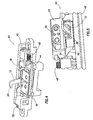
- FIG. 4 shows a release mechanism in accordance with embodiments of the invention
- Figure 5 shows a partial view of the release mechanism of Figure 4.
- Figure 6 shows a partially exploded view of the release mechanism of Figure 4.
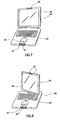
- FIG. 7 shows a notebook-type portable computer system in accordance with embodiments of the invention.
- Figure 8 shows a tablet-type portable computer system in accordance with embodiments of the invention.
- latch mechanism 10 comprising a hook 12 pivotally attached to a first component 14.
- Hook 12 is connected at pivot 16 and has a first position 18 recessed within first component 14 and a second position 20 extended from the first component.
- hook 12 engages receptacle 22 that is disposed within second component 24.
- Magnet 26 is disposed within second component 24 and maintains hook 12 in second position 20.
- latch mechanism 10 is shown in an unlatched position where first component 14 is moved away from the second component (not shown). As the distance between magnet 26 and hook 12 increases, the magnetic force acting on the hook decreases. Hook 12 is biased to first position 18 such that, as the magnetic force decreases, hook 12 will return to the first position and be recessed within first component 14. Hook 12 may be biased by a spring or simply by gravity causing the hook to rotate about pivot 16. Thus, as the components are moved away from each other, hook 12 will automatically move back to the recessed first position 18 so as not to project above the surface of first component 14.
- release mechanism 40 comprises push-button 42 that actuates a cam slider 44 that engages hook 12.
- Release mechanism 40 also comprises hook retainer 46 that provides a pivot connection to hook 12.
- Spring 48 and spring 50 bias, respectively, cam slider 44 and push-button 42 to an initial position where hook 12 can freely pivot.
- Hook 12 may also have a spring that biases it to the recessed first position 18 or may be weight-biased such that gravitational force pulls the hook to the first position.
- release mechanism 40 The actuation of release mechanism 40 is performed by depressing push-button 42 so as to translate cam slider 44.
- angled surface 52 engages cam surface 54 on cam slider 44 and translates the cam slider perpendicular relative to the direction the button is pushed.
- Stationary guide 56 controls the direction of motion of cam slider 44 and provides a mounting location for hook retainer 46.
- cam slider 44 translates, slider tab 58 contacts hook tab 60 (see Figure 6) and causes hook 12 to release from receptacle 22. Once released from receptacle 22, hook 12 can rotate from the second position 20 to the first position 18.
- push-button 42 Once push-button 42 is released, spring 48 pulls cam slider 44 back to its initial position and spring 50 pushes button 42 back to its initial position. Absent magnetic attraction of magnet 26, hook 12 will remain in the recessed first position 18. Therefore, to separate first component 14 from second component 24, push-button 42 is depressed so as to disengage hook 12 from receptacle 22. The components are then moved apart and push-button 42 can be released. Releasing push-button 42 will not extend hook 12 outside of first component 14.
- Hook 12 may be partially or wholly constructed of sheet metal or any other material that would be attracted by magnet 26.
- Magnet 26 may be a permanent magnet having a sufficient magnetic field to attract hook 12 without detrimentally affecting the performance of the portable computer system or display.
- latch mechanism 10 is installed on a notebook-type portable computer system 50.
- Hook 12 and release mechanism 40 are installed on main chassis 52.
- Magnet 26 and receptacle 22 are disposed on display panel 54.
- the placement of the components could be reversed.
- latch mechanism 10 could be installed on a tablet-type portable computer system 60.
- Tablet system 60 comprises main chassis 62 to which a display panel 64 is pivotally connected.
- Display panel 64 can be closed with screen 66 facing chassis 62 or facing away from the chassis. Because display panel 64 can be closed in one of two arrangements.
- magnet 26 is located near the mid-plane of display panel 64 with a receptacle 22 located on either surface of the panel. In this manner, latch mechanism 10 operates with panel 62 in either position. In altemate embodiments, the placement of the components could be reversed.
Landscapes
- Engineering & Computer Science (AREA)
- Theoretical Computer Science (AREA)
- Computer Hardware Design (AREA)
- Physics & Mathematics (AREA)
- Human Computer Interaction (AREA)
- General Engineering & Computer Science (AREA)
- General Physics & Mathematics (AREA)
- Electromagnetism (AREA)
- Mathematical Physics (AREA)
- Mechanical Engineering (AREA)
- Casings For Electric Apparatus (AREA)
- Buckles (AREA)
- Telephone Set Structure (AREA)
- Load-Engaging Elements For Cranes (AREA)
- Input From Keyboards Or The Like (AREA)
- Supports Or Holders For Household Use (AREA)
Abstract
Description
- Portable computers are compact, lightweight computing devices and may comprise any portable electronic device, for example, notebook computers, personal digital assistants, tablet personal computers, and laptop computers. Many portable computer systems utilize two rotatably connected components that can be arranged in opened or closed positions as desired. For example, notebook computer systems have a display panel that is rotatably connected to a main computer chassis. The display panel can be closed against the main chassis in a clam-shell type configuration that provides a compact package for portability and protects the screen and keyboard. Many systems include latching mechanisms that connect the display panel to the main body when the display panel is in the closed position.
- Latching mechanisms that involve complicated operation, are difficult to use, or require two hands and/or considerable force to operate may not be desirable. Some latching mechanisms require user intervention for engagement and disengagement, thus increasing the difficulty of use. Many latching systems utilize one or more latching members that project above the surface of the system and are susceptible to being caught on something and possibly breaking.
- Therefore, as can be appreciated, there is a need for a latching mechanism for portable computer systems that provides simple, compact, one-handed operation. The problems noted above are solved in large part by a latching mechanism comprising a hook connected to a first component. The hook has a first position that is recessed within the first component and a second position extended from the first component. The latching mechanism further comprises a receptacle disposed within a second component and engaged with the hook. A magnet is disposed within the second component and moves the hook from the first position to the second position, as the second component is disposed in close proximity to the first component. A push-button release mechanism is disposed within the first component and moves the hook from the second position so as to disengage said hook from said receptacle.
- For a detailed description of exemplary embodiments of the invention, reference will now be made to the accompanying drawings in which:
- Figure 1 shows a latching mechanism in a latched position in accordance with embodiments of the invention;
- Figure 2 shows the latching mechanism of Figure 1 in an unlatched and partially opened position;
- Figure 3 shows the latching mechanism of Figure 1 in an unlatched and fully open position;
- Figure 4 shows a release mechanism in accordance with embodiments of the invention;
- Figure 5 shows a partial view of the release mechanism of Figure 4;
- Figure 6 shows a partially exploded view of the release mechanism of Figure 4;
- Figure 7 shows a notebook-type portable computer system in accordance with embodiments of the invention; and
- Figure 8 shows a tablet-type portable computer system in accordance with embodiments of the invention.
- Certain terms are used throughout the following description and claims to refer to particular system components. As one skilled in the art will appreciate, computer companies may refer to a component by different names. This document does not intend to distinguish between components that differ in name but not function. In the following discussion and in the claims, the terms "including" and "comprising" are used in an open-ended fashion, and thus should be interpreted to mean "including, but not limited to...."
- The following discussion is directed to various embodiments of the invention. Referring now to Figure 1,
latch mechanism 10 is shown comprising ahook 12 pivotally attached to afirst component 14. Hook 12 is connected atpivot 16 and has afirst position 18 recessed withinfirst component 14 and asecond position 20 extended from the first component. When insecond position 20, hook 12 engagesreceptacle 22 that is disposed withinsecond component 24.Magnet 26 is disposed withinsecond component 24 and maintainshook 12 insecond position 20. - As shown in Figure 2, as first component and
second component 24 are disposed close to each other, the magnetic attraction betweenmagnet 26 andhook 12 increases. This magnetic attraction causeshook 12 to rotate upward tosecond position 20. Thus, as the components are moved in close proximity to each other,hook 12 will automatically move fromfirst position 18 tosecond position 20. As the components are moved adjacent to each other,upper edge 28 ofhook 12contacts surface 30 ofsecond component 24 and causes the hook to temporarily rotate and enteraperture 32 ofreceptacle 22. Magnet 26 maintainshook 12 in thesecond position 20 and engaged withreceptacle 22. - Referring now to Figure 3,
latch mechanism 10 is shown in an unlatched position wherefirst component 14 is moved away from the second component (not shown). As the distance betweenmagnet 26 andhook 12 increases, the magnetic force acting on the hook decreases.Hook 12 is biased tofirst position 18 such that, as the magnetic force decreases,hook 12 will return to the first position and be recessed withinfirst component 14. Hook 12 may be biased by a spring or simply by gravity causing the hook to rotate aboutpivot 16. Thus, as the components are moved away from each other,hook 12 will automatically move back to the recessedfirst position 18 so as not to project above the surface offirst component 14. - Referring now to Figures 4-6,
release mechanism 40 comprises push-button 42 that actuates acam slider 44 that engageshook 12.Release mechanism 40 also compriseshook retainer 46 that provides a pivot connection to hook 12.Spring 48 andspring 50 bias, respectively,cam slider 44 and push-button 42 to an initial position wherehook 12 can freely pivot. Hook 12 may also have a spring that biases it to the recessedfirst position 18 or may be weight-biased such that gravitational force pulls the hook to the first position. - The actuation of
release mechanism 40 is performed by depressing push-button 42 so as to translatecam slider 44. As shown in Figure 5, as push-button 42 is depressed,angled surface 52 engagescam surface 54 oncam slider 44 and translates the cam slider perpendicular relative to the direction the button is pushed.Stationary guide 56 controls the direction of motion ofcam slider 44 and provides a mounting location forhook retainer 46. Ascam slider 44 translates,slider tab 58 contacts hook tab 60 (see Figure 6) and causeshook 12 to release fromreceptacle 22. Once released fromreceptacle 22,hook 12 can rotate from thesecond position 20 to thefirst position 18. - Once push-
button 42 is released,spring 48pulls cam slider 44 back to its initial position andspring 50 pushesbutton 42 back to its initial position. Absent magnetic attraction ofmagnet 26,hook 12 will remain in the recessedfirst position 18. Therefore, to separatefirst component 14 fromsecond component 24, push-button 42 is depressed so as to disengagehook 12 fromreceptacle 22. The components are then moved apart and push-button 42 can be released. Releasing push-button 42 will not extendhook 12 outside offirst component 14. -
Hook 12 may be partially or wholly constructed of sheet metal or any other material that would be attracted bymagnet 26.Magnet 26 may be a permanent magnet having a sufficient magnetic field to attracthook 12 without detrimentally affecting the performance of the portable computer system or display. - Referring now to Figure 7,
latch mechanism 10 is installed on a notebook-typeportable computer system 50. Hook 12 andrelease mechanism 40 are installed onmain chassis 52.Magnet 26 andreceptacle 22 are disposed ondisplay panel 54. In alternate embodiments, the placement of the components could be reversed. - Referring now to Figure 8,
latch mechanism 10 could be installed on a tablet-typeportable computer system 60.Tablet system 60 comprisesmain chassis 62 to which adisplay panel 64 is pivotally connected.Display panel 64 can be closed withscreen 66 facingchassis 62 or facing away from the chassis. Becausedisplay panel 64 can be closed in one of two arrangements. In some embodiments,magnet 26 is located near the mid-plane ofdisplay panel 64 with areceptacle 22 located on either surface of the panel. In this manner,latch mechanism 10 operates withpanel 62 in either position. In altemate embodiments, the placement of the components could be reversed. - The above discussion is meant to be illustrative of the principles and various embodiments of the present invention. Numerous variations and modifications will become apparent to those skilled in the art once the above disclosure is fully appreciated. For example, the orientation and arrangement of the hook and receptacle could be reversed such that the push-button would be on the second component and the receptacle on the first component.
Claims (10)
- A latching mechanism (10) comprising:a hook (12) connected to a first component (14), wherein said hook has a first position (18) recessed within the first component and a second position (20) projecting from the first component;a receptacle (22) disposed within a second component (24) and engaged with said hook (12) when said hook is in the second position (20);a magnet (26) disposed within the second component (24), wherein said magnet moves said hook (12) from the first position (18) to the second position (20) as the second component (24) is disposed in close proximity to the first component (14); anda push-button release mechanism (40) disposed within the first component (14), wherein said release mechanism (40) moves said hook (12) from the second position (20) so as to disengage said hook from said receptacle (22).
- The latching mechanism (10) of claim 1 wherein said hook (12) is biased to the first position (18).
- The latching mechanism (10) of claim 1 further comprising a spring that biases said hook (12) to the first position (18).
- The latching mechanism (10) of claim 2 wherein said hook (12) is weight-biased to the first position (18).
- The latching mechanism (10) of claim 1 wherein said push-button release mechanism (40) further comprises:a cam slider that moves said hook (12) from the second position (20) to the first position (18);a cam surface that engages said cam slider; anda button connected to said cam surface.
- The latching mechanism (10) of claim 5 further comprising a first spring that urges said cam slider to a position not engaged with said hook (12) and a second spring that urges said button to a non-actuated position.
- The latching mechanism (10) of claim 5 wherein said cam slider moves in a direction perpendicular to the pivot axis and said cam surface moves in a direction parallel to the pivot axis.
- The latching mechanism (10) of claim 1 wherein said push-button release mechanism (40) further comprises:a button actuatable from outside the first component (14).a cam surface connected to said button; anda cam slider engages said cam surface and moves said hook (12) from the second position (20) to the first position (18).
- The latching mechanism (10) of claim 1 wherein the first component (14) is a main chassis of a notebook computer system and the second component (24) is a display panel of a notebook computer system.
- The latching mechanism (10) of claim 1 wherein the first component (14) is a main chassis of a tablet computer system and the second component (24) is a display panel of a tablet computer system.
Applications Claiming Priority (1)
| Application Number | Priority Date | Filing Date | Title |
|---|---|---|---|
| US10/938,791 US7405927B2 (en) | 2004-09-10 | 2004-09-10 | Push-button latching mechanism |
Publications (3)
| Publication Number | Publication Date |
|---|---|
| EP1635246A2 true EP1635246A2 (en) | 2006-03-15 |
| EP1635246A3 EP1635246A3 (en) | 2008-11-05 |
| EP1635246B1 EP1635246B1 (en) | 2011-11-02 |
Family
ID=35207740
Family Applications (1)
| Application Number | Title | Priority Date | Filing Date |
|---|---|---|---|
| EP20050255486 Ceased EP1635246B1 (en) | 2004-09-10 | 2005-09-07 | Push-button latching mechanism |
Country Status (5)
| Country | Link |
|---|---|
| US (1) | US7405927B2 (en) |
| EP (1) | EP1635246B1 (en) |
| JP (1) | JP2006079607A (en) |
| CN (1) | CN100504718C (en) |
| TW (1) | TWI347393B (en) |
Cited By (2)
| Publication number | Priority date | Publication date | Assignee | Title |
|---|---|---|---|---|
| WO2008013739A3 (en) * | 2006-07-25 | 2008-03-13 | Hewlett Packard Development Co | Anti-rotation mechanism for an electronic device |
| KR101068916B1 (en) * | 2008-07-03 | 2011-09-29 | 삼성메디슨 주식회사 | Medical devices |
Families Citing this family (52)
| Publication number | Priority date | Publication date | Assignee | Title |
|---|---|---|---|---|
| US7959194B2 (en) * | 2005-05-20 | 2011-06-14 | Volvo Group North America, Llc | Latch assembly and arrangement including a latch assembly |
| JP2007074446A (en) * | 2005-09-07 | 2007-03-22 | Toshiba Corp | Portable information device with built-in wireless communication antenna |
| CN2850207Y (en) * | 2005-10-25 | 2006-12-20 | 鸿富锦精密工业(深圳)有限公司 | Combination of hook device |
| CN2874597Y (en) * | 2006-01-10 | 2007-02-28 | 鸿富锦精密工业(深圳)有限公司 | Buckle device combination |
| TWI329795B (en) * | 2006-09-27 | 2010-09-01 | Compal Electronics Inc | Magnetic controlled fastener device |
| US7543862B2 (en) * | 2006-11-20 | 2009-06-09 | Inventec Corporation | Magnet latch |
| CN100592845C (en) * | 2006-12-22 | 2010-02-24 | 鸿富锦精密工业(深圳)有限公司 | Snapping device |
| JP2008165367A (en) * | 2006-12-27 | 2008-07-17 | Toshiba Corp | Electronics |
| TWM314361U (en) * | 2007-01-19 | 2007-06-21 | Quanta Comp Inc | Latch design of a notebook computer |
| US7438333B2 (en) * | 2007-01-30 | 2008-10-21 | Inventec Corporation | Magnetic latch assembly |
| KR20080076380A (en) * | 2007-02-15 | 2008-08-20 | 삼성전자주식회사 | Information processing device |
| US7606024B2 (en) * | 2007-08-16 | 2009-10-20 | International Business Machines Corporation | Computer lock system |
| TWI340618B (en) * | 2007-10-23 | 2011-04-11 | Htc Corp | Electronic device |
| TWI340009B (en) * | 2008-01-18 | 2011-04-01 | Quanta Comp Inc | Electronic device and latch structure thereof |
| CN101660555A (en) * | 2008-08-26 | 2010-03-03 | 鸿富锦精密工业(深圳)有限公司 | Fastening device and electronic equipment using same |
| JP2010250513A (en) * | 2009-04-14 | 2010-11-04 | Fujitsu Ltd | Electronics |
| CN101989105A (en) * | 2009-07-31 | 2011-03-23 | 鸿富锦精密工业(深圳)有限公司 | Fastener device of laptop |
| CN102147844B (en) * | 2010-02-05 | 2013-03-20 | 鸿富锦精密工业(深圳)有限公司 | laptop |
| JP2012014460A (en) * | 2010-06-30 | 2012-01-19 | Fujitsu Ltd | Electronic apparatus and joint method of housing thereof |
| TWI548250B (en) * | 2010-11-15 | 2016-09-01 | 富智康(香港)有限公司 | Portable electronic device |
| KR101767212B1 (en) * | 2011-01-18 | 2017-08-10 | 삼성전자주식회사 | Tilt angle switchable hinge assembly for portable electronic device |
| US8576562B2 (en) | 2011-02-16 | 2013-11-05 | Dell Products L.P. | Latching system for convertible information handling system |
| TWM416311U (en) * | 2011-05-09 | 2011-11-11 | Wistron Corp | Electronic apparatus and fixed structure thereof |
| WO2013002796A1 (en) * | 2011-06-30 | 2013-01-03 | Hewlett-Packard Development Company, L.P. | Latch and panels of computing systems |
| CN103075053B (en) * | 2011-10-26 | 2015-01-07 | 纬创资通股份有限公司 | Lock and portable electronic device |
| US20140313665A1 (en) * | 2011-12-05 | 2014-10-23 | Michael Delpier | A Computing System Including A First And Second Housing And Polar Magnets |
| US20130178161A1 (en) * | 2012-01-08 | 2013-07-11 | Arthur M. Shulenberger | Multifunctional carrying case for a tablet computer |
| WO2013112166A2 (en) * | 2012-01-26 | 2013-08-01 | Empire Technology Development Llc | Sprung latch fastener |
| TWI454889B (en) * | 2012-03-30 | 2014-10-01 | Jarllytec Co Ltd | A connector with a resetting mechanism |
| TWI489249B (en) * | 2012-08-08 | 2015-06-21 | Wistron Corp | Portable electronic device and housing structure |
| KR101991940B1 (en) * | 2012-08-08 | 2019-06-24 | 삼성전자주식회사 | Portable electronic apparatus |
| CN104620188A (en) * | 2012-09-12 | 2015-05-13 | 惠普发展公司,有限责任合伙企业 | Latch for computer case |
| US9828177B2 (en) * | 2013-02-22 | 2017-11-28 | Orbis Corporation | Waste container with gravity latch and latch deactivation system |
| CN104111696B (en) | 2013-04-17 | 2017-05-10 | 纬创资通(昆山)有限公司 | Fastening mechanism and portable electronic device |
| TWI529517B (en) * | 2013-04-19 | 2016-04-11 | 仁寶電腦工業股份有限公司 | Connecting assembly and electronic device having the same |
| CN104181981A (en) * | 2013-05-23 | 2014-12-03 | 名硕电脑(苏州)有限公司 | Electronic device capable of being opened by utilizing magnetic force |
| TWI482575B (en) * | 2013-07-11 | 2015-04-21 | Wistron Corp | Electronic system and connecting mechanism thereof |
| US9690332B2 (en) * | 2013-10-09 | 2017-06-27 | Kabushiki Kaisha Toshiba | Electronic device, combining device, and detaching method |
| EP2924198A1 (en) * | 2014-03-26 | 2015-09-30 | Alban Giacomo S.p.A. | Forced entry resistant lock |
| EP2924208B1 (en) * | 2014-03-26 | 2019-06-26 | Alban Giacomo S.p.A. | Forced entry resistant lock |
| TWI563364B (en) | 2015-03-23 | 2016-12-21 | Compal Electronics Inc | An electronic apparatus having a base |
| US11015631B2 (en) | 2016-01-29 | 2021-05-25 | Hewlett-Packard Development Company, L.P. | Retractable locks |
| US11193313B2 (en) * | 2016-09-22 | 2021-12-07 | Dirak Dieter Ramsauer Konstruktionselemente Gmbh | Electromechanical closure having a rotary latch arrangement with an evaluatable door contact for controlling a display device such as an LED module |
| CN106292893B (en) * | 2016-10-24 | 2023-04-28 | 合肥联宝信息技术有限公司 | Electronic equipment |
| KR101871990B1 (en) * | 2016-12-12 | 2018-07-31 | 배귀석 | Sliding door locking device using magnetic |
| CN106761063B (en) * | 2016-12-27 | 2020-02-21 | 武昌船舶重工集团有限公司 | Bolt |
| US10461451B1 (en) * | 2018-06-12 | 2019-10-29 | Aplex Technology Inc. | Electronic device quick release structure |
| CN110077257B (en) * | 2019-05-18 | 2020-12-01 | 六安永贞匠道机电科技有限公司 | An encrypted charging docking system for electric vehicles |
| WO2021101515A1 (en) * | 2019-11-19 | 2021-05-27 | Hewlett-Packard Development Company, L.P. | Latch mechanism |
| CN113757233B (en) * | 2020-06-04 | 2023-07-25 | 光宝电子(广州)有限公司 | Fastener structure |
| US12084892B2 (en) | 2021-05-01 | 2024-09-10 | A.G. Stacker Inc. | Automatic blocking device for limiting a sliding movement of a first structure mounted adjacent to a second structure |
| US12433381B2 (en) | 2022-07-15 | 2025-10-07 | United States Luggage | Push button expansion system for luggage |
Citations (2)
| Publication number | Priority date | Publication date | Assignee | Title |
|---|---|---|---|---|
| JPH0832254A (en) | 1994-07-20 | 1996-02-02 | Mitsubishi Electric Corp | Locking device for portable electronic devices |
| US20040189017A1 (en) | 2003-03-24 | 2004-09-30 | Wen-Hsiang Chen | Magnetic locking device |
Family Cites Families (10)
| Publication number | Priority date | Publication date | Assignee | Title |
|---|---|---|---|---|
| DE539153C (en) * | 1930-03-04 | 1931-11-23 | Sudhaus Soehne Heinrich | Case lock with a central lock and several secondary locks that can be unlocked from the central lock |
| JP2002185160A (en) | 2000-05-09 | 2002-06-28 | Sony Computer Entertainment Inc | Box for electronic device and electronic device |
| US6507485B2 (en) * | 2001-01-04 | 2003-01-14 | Apple Computer, Inc. | Spring loaded hinge apparatus |
| US6659516B2 (en) * | 2001-01-05 | 2003-12-09 | Apple Computer, Inc. | Locking system for a portable computer |
| US6653919B2 (en) * | 2001-02-02 | 2003-11-25 | Wistron Corp | Magnetic closure apparatus for portable computers |
| US6937465B2 (en) * | 2002-01-31 | 2005-08-30 | Samsung Electronics Co., Ltd. | Portable computer having a latch apparatus |
| US6517129B1 (en) * | 2002-04-15 | 2003-02-11 | Compal Electronics, Inc. | Lock device for an electronic appliance |
| TWI225980B (en) * | 2003-10-24 | 2005-01-01 | Asustek Comp Inc | Apparatus with hidden latch |
| TWI260961B (en) * | 2004-02-03 | 2006-08-21 | Wistron Corp | Machinery system including a rotatable hook |
| TWM270634U (en) * | 2004-08-19 | 2005-07-11 | Compal Electronics Inc | Engagement module of portable computer |
-
2004
- 2004-09-10 US US10/938,791 patent/US7405927B2/en not_active Expired - Lifetime
-
2005
- 2005-08-10 TW TW094127166A patent/TWI347393B/en not_active IP Right Cessation
- 2005-09-01 JP JP2005253435A patent/JP2006079607A/en active Pending
- 2005-09-07 EP EP20050255486 patent/EP1635246B1/en not_active Ceased
- 2005-09-12 CN CNB2005100981944A patent/CN100504718C/en not_active Expired - Fee Related
Patent Citations (2)
| Publication number | Priority date | Publication date | Assignee | Title |
|---|---|---|---|---|
| JPH0832254A (en) | 1994-07-20 | 1996-02-02 | Mitsubishi Electric Corp | Locking device for portable electronic devices |
| US20040189017A1 (en) | 2003-03-24 | 2004-09-30 | Wen-Hsiang Chen | Magnetic locking device |
Cited By (4)
| Publication number | Priority date | Publication date | Assignee | Title |
|---|---|---|---|---|
| WO2008013739A3 (en) * | 2006-07-25 | 2008-03-13 | Hewlett Packard Development Co | Anti-rotation mechanism for an electronic device |
| US7515405B2 (en) | 2006-07-25 | 2009-04-07 | Hewlett-Packard Development Company, L.P. | Anti-rotation mechanism for an electronic device |
| CN101495938B (en) * | 2006-07-25 | 2012-07-04 | 惠普开发有限公司 | Anti-rotation mechanism for an electronic device |
| KR101068916B1 (en) * | 2008-07-03 | 2011-09-29 | 삼성메디슨 주식회사 | Medical devices |
Also Published As
| Publication number | Publication date |
|---|---|
| TWI347393B (en) | 2011-08-21 |
| CN1746812A (en) | 2006-03-15 |
| JP2006079607A (en) | 2006-03-23 |
| US7405927B2 (en) | 2008-07-29 |
| CN100504718C (en) | 2009-06-24 |
| TW200619484A (en) | 2006-06-16 |
| US20060056140A1 (en) | 2006-03-16 |
| EP1635246A3 (en) | 2008-11-05 |
| EP1635246B1 (en) | 2011-11-02 |
Similar Documents
| Publication | Publication Date | Title |
|---|---|---|
| US7405927B2 (en) | Push-button latching mechanism | |
| US6929291B2 (en) | Magnetic lock | |
| US8109541B2 (en) | Latching structure of mobile electronic device | |
| US8385063B2 (en) | Electronic device | |
| US8947871B2 (en) | Portable electronic device and slide rail device | |
| TW201543985A (en) | Handle module | |
| TW200528006A (en) | Machinery system including a rotatable hook | |
| JPH03101298A (en) | Handle and latch assembly of portable personal computer | |
| EP4034966B1 (en) | Display devices of computing devices | |
| US7773376B2 (en) | Foldable electronic device | |
| US7436656B2 (en) | Portable computer having improved latch mechanism | |
| EP1643059B1 (en) | Sliding latching mechanism | |
| US7876567B2 (en) | Foldable electronic device and latch mechanism applied in the foldable electronic device | |
| US20070121303A1 (en) | Multi-Configuration Portable Electronic Device and Guiding Module Thereof | |
| US8553403B2 (en) | Foldable electronic device with magnetic latch | |
| US20100309614A1 (en) | Electronic device | |
| CN102465641A (en) | Latch mechanism and portable computer | |
| CN100399868C (en) | Mechanism system with movable clamping hook | |
| US20060082962A1 (en) | Portable electronic apparatus having improved latch mechanism | |
| US20070120373A1 (en) | Latch mechanism | |
| CN101727131B (en) | Latch Structure of Portable Electronic Devices | |
| CN101431206A (en) | Fixing mechanism for battery hook | |
| US20070146984A1 (en) | Hinge fastening apparatus | |
| US8613551B2 (en) | Slide rail structure for electronic device | |
| EP1806644A2 (en) | Multi-configuration portable electronic device and guiding module thereof |
Legal Events
| Date | Code | Title | Description |
|---|---|---|---|
| PUAI | Public reference made under article 153(3) epc to a published international application that has entered the european phase |
Free format text: ORIGINAL CODE: 0009012 |
|
| AK | Designated contracting states |
Kind code of ref document: A2 Designated state(s): AT BE BG CH CY CZ DE DK EE ES FI FR GB GR HU IE IS IT LI LT LU LV MC NL PL PT RO SE SI SK TR |
|
| AX | Request for extension of the european patent |
Extension state: AL BA HR MK YU |
|
| PUAL | Search report despatched |
Free format text: ORIGINAL CODE: 0009013 |
|
| RIC1 | Information provided on ipc code assigned before grant |
Ipc: E05C 19/16 20060101ALI20080923BHEP Ipc: G06F 1/16 20060101AFI20051110BHEP |
|
| AK | Designated contracting states |
Kind code of ref document: A3 Designated state(s): AT BE BG CH CY CZ DE DK EE ES FI FR GB GR HU IE IS IT LI LT LU LV MC NL PL PT RO SE SI SK TR |
|
| AX | Request for extension of the european patent |
Extension state: AL BA HR MK YU |
|
| 17P | Request for examination filed |
Effective date: 20090306 |
|
| 17Q | First examination report despatched |
Effective date: 20090406 |
|
| AKX | Designation fees paid |
Designated state(s): DE GB |
|
| GRAP | Despatch of communication of intention to grant a patent |
Free format text: ORIGINAL CODE: EPIDOSNIGR1 |
|
| GRAS | Grant fee paid |
Free format text: ORIGINAL CODE: EPIDOSNIGR3 |
|
| GRAA | (expected) grant |
Free format text: ORIGINAL CODE: 0009210 |
|
| AK | Designated contracting states |
Kind code of ref document: B1 Designated state(s): DE GB |
|
| REG | Reference to a national code |
Ref country code: GB Ref legal event code: FG4D |
|
| REG | Reference to a national code |
Ref country code: DE Ref legal event code: R096 Ref document number: 602005030924 Country of ref document: DE Effective date: 20120202 |
|
| PLBE | No opposition filed within time limit |
Free format text: ORIGINAL CODE: 0009261 |
|
| STAA | Information on the status of an ep patent application or granted ep patent |
Free format text: STATUS: NO OPPOSITION FILED WITHIN TIME LIMIT |
|
| 26N | No opposition filed |
Effective date: 20120803 |
|
| REG | Reference to a national code |
Ref country code: DE Ref legal event code: R097 Ref document number: 602005030924 Country of ref document: DE Effective date: 20120803 |
|
| PGFP | Annual fee paid to national office [announced via postgrant information from national office to epo] |
Ref country code: DE Payment date: 20180821 Year of fee payment: 14 |
|
| PGFP | Annual fee paid to national office [announced via postgrant information from national office to epo] |
Ref country code: GB Payment date: 20180823 Year of fee payment: 14 |
|
| REG | Reference to a national code |
Ref country code: DE Ref legal event code: R119 Ref document number: 602005030924 Country of ref document: DE |
|
| PG25 | Lapsed in a contracting state [announced via postgrant information from national office to epo] |
Ref country code: DE Free format text: LAPSE BECAUSE OF NON-PAYMENT OF DUE FEES Effective date: 20200401 |
|
| GBPC | Gb: european patent ceased through non-payment of renewal fee |
Effective date: 20190907 |
|
| PG25 | Lapsed in a contracting state [announced via postgrant information from national office to epo] |
Ref country code: GB Free format text: LAPSE BECAUSE OF NON-PAYMENT OF DUE FEES Effective date: 20190907 |