EP1635013A2 - Quick action door lock - Google Patents
Quick action door lock Download PDFInfo
- Publication number
- EP1635013A2 EP1635013A2 EP20050380155 EP05380155A EP1635013A2 EP 1635013 A2 EP1635013 A2 EP 1635013A2 EP 20050380155 EP20050380155 EP 20050380155 EP 05380155 A EP05380155 A EP 05380155A EP 1635013 A2 EP1635013 A2 EP 1635013A2
- Authority
- EP
- European Patent Office
- Prior art keywords
- wards
- frame
- key
- lock
- levers
- Prior art date
- Legal status (The legal status is an assumption and is not a legal conclusion. Google has not performed a legal analysis and makes no representation as to the accuracy of the status listed.)
- Withdrawn
Links
Images


Classifications
-
- E—FIXED CONSTRUCTIONS
- E05—LOCKS; KEYS; WINDOW OR DOOR FITTINGS; SAFES
- E05B—LOCKS; ACCESSORIES THEREFOR; HANDCUFFS
- E05B29/00—Cylinder locks and other locks with plate tumblers which are set by pushing the key in
- E05B29/0006—Other locks than cylinder locks with plate tumblers
-
- E—FIXED CONSTRUCTIONS
- E05—LOCKS; KEYS; WINDOW OR DOOR FITTINGS; SAFES
- E05B—LOCKS; ACCESSORIES THEREFOR; HANDCUFFS
- E05B21/00—Locks with lamelliform tumblers which are not set by the insertion of the key and in which the tumblers do not follow the movement of the bolt e.g. Chubb-locks
-
- E—FIXED CONSTRUCTIONS
- E05—LOCKS; KEYS; WINDOW OR DOOR FITTINGS; SAFES
- E05B—LOCKS; ACCESSORIES THEREFOR; HANDCUFFS
- E05B35/00—Locks for use with special keys or a plurality of keys ; keys therefor
-
- E—FIXED CONSTRUCTIONS
- E05—LOCKS; KEYS; WINDOW OR DOOR FITTINGS; SAFES
- E05B—LOCKS; ACCESSORIES THEREFOR; HANDCUFFS
- E05B15/00—Other details of locks; Parts for engagement by bolts of fastening devices
- E05B15/10—Bolts of locks or night latches
- E05B15/108—Bolts with multiple head
-
- E—FIXED CONSTRUCTIONS
- E05—LOCKS; KEYS; WINDOW OR DOOR FITTINGS; SAFES
- E05B—LOCKS; ACCESSORIES THEREFOR; HANDCUFFS
- E05B19/00—Keys; Accessories therefor
- E05B19/0017—Key profiles
- E05B19/0041—Key profiles characterized by the cross-section of the key blade in a plane perpendicular to the longitudinal axis of the key
- E05B19/0047—Key profiles characterized by the cross-section of the key blade in a plane perpendicular to the longitudinal axis of the key with substantially circular or star-shape cross-section
-
- E—FIXED CONSTRUCTIONS
- E05—LOCKS; KEYS; WINDOW OR DOOR FITTINGS; SAFES
- E05B—LOCKS; ACCESSORIES THEREFOR; HANDCUFFS
- E05B63/00—Locks or fastenings with special structural characteristics
- E05B63/0017—Locks with sliding bolt without provision for latching
Definitions
- the present invention relates to a door lock with mechanical locking means, which opens by simply introducing the corresponding key without the need for turning said key and by turning an externally actuated doorknob. Closure of the lock is achieved by simply turning said doorknob without the need to use the key.
- Opening and closing requires only a half turn (180°) of the doorknob, making the operation of the lock a very quick process.
- the actuating key incorporates a teethed or crenellated profile on one of its edges, which acts on the locking means of the lock by turning said key.
- the present invention relates to a lock that allows a quick and easy operation of the lock in such way that it requires only the introduction of the key and the operation of a doorknob to open it, without the need to turn said key in its place.
- Closing takes place by operating the doorknob without introducing the key.
- the operation is very quick, due to the fact that the doorknob only needs a half turn (180°) in any direction for opening or for closing.
- the present invention provides a door lock comprising a frame which is incorporated into the lock housing and which can slide horizontally in the interior of the latter, said frame having one or more latches securely connected to it that can protrude outside of the lock and act as closing elements when they are introduced into the door jamb as the frame is moved to that side, while they are housed in the interior of the lock housing when the frame is moved in the opposite direction, enabling in this way the opening of the door.
- the frame is linked to two external manually operated doorknobs, one at each side of the door, in such way that a simple 180° turn of one of the doorknobs moves the frame to one side or the other.
- the invention provides a system of wards which are actuated with the corresponding key, particularly so that it is only necessary to insert the key without having to turn it afterwards to open the door.
- the wards are laid out in the lock housing transversally in relation to the movement of the frame and can perform small movements in vertical direction.
- the wards comprise a series of superposed metal plates including a central window for inserting the key and external extensions or collars of different length on each ward, said plates holding respective springs which push the wards through to their location of maximum vertical displacement so as to be positioned in the path of a number of interior protrusions of the frame so that, upon movement of the frame, these protrusions will impact against the ward collars in order to prevent unlocking the lock without prior introduction of the key.
- the collars of each of the wards are of different length, matching crenellated cut-outs provided on the key profile, so that the introduction of the adequate key causes each of the wards to butt, by means of its respective window, at the corresponding cut-out on the key, limiting the movement of the ward towards the exterior through the corresponding spring, and, in this way, aligning all of the wards' collars in a position that will not interfere with the path of the interior protrusions of the frame and therefore enabling the lock's movement by operating one of the external doorknobs.
- the present invention provides a lock that enables the opening of the door in a quick and easy way as it only requires to insert the key and to operate the doorknob without the need to turn the key.
- this invention provides a reduced wear on the key and on the wards by eliminating the need to turn the key for unlocking the lock.
- the protrusions on the frame are chamfered on one side so that, when closing the lock and sliding the frame, they butt at the ward assembly forcing them to retract, acting against the force exerted by the compression springs, so that the lock can be closed by operating the external doorknob without the need to insert the key.
- the manually operated doorknobs are mounted at the ends of a shaft mounted transversally on the lock housing and onto which a freewheel is located that is connected from its periphery to a rod which is movably connected to the sliding frame in such way that a simple 180° turn will move the frame in order to open or close the lock.
- Another objective of the present invention is to provide a system of wards that acts upon the key simultaneously from the top and the bottom sides, thus permitting a greater number of different combinations and therefore of different keys.
- a wards assembly comprising two types of wards in an alternative arrangement, each ward being inverted in relation to the two neighbouring wards and, in particular, if one group of wards is facing up, the wards in the other group will be facing down.
- the compression springs are disposed between the ward of one group and the subsequent ward of the other group so that both wards are displaced vertically in opposing directions, each invading the respective paths of the internal protrusions of the frame.
- the key presents an upper crenellated profile and a lower crenellated profile, in correspondence with the two groups of wards, as one of them will operate by coupling to the key from its upper, while the other will do it from its lower part, thus providing a larger number of different combinations for the lock.
- a lock in accordance with the invention comprises a rectangular frame (2) that is housed inside the lock housing and is capable of sliding horizontally along the interior of the latter.
- the frame is produced preferably out of thin plate material and with a width equal to the depth of the lock housing (1) that surrounds the remaining mechanisms such as the driving and blocking system for the wards, as explained later.
- a number of latches (3) are securely attached to the frame (2) so that they can emerge relative to the door edge acting as closing elements when the frame (2) is horizontally moved to that side, as demonstrated in figures 1 and 2, wherein said latches are introduced into the door jamb.
- the horizontal movement of said frame (2) is realised by way of a freewheel (20) and a connecting rod (21) provided in its interior, one of its ends tilting around a frame stud (27), while the other end of the connecting rod (21) tilts around a stud provided on the periphery of the freewheel (26).
- the freewheel (20) comprises two discs (22, 22') securely mounted in parallel on a central point (25) of the freewheel (20), which is traversed by a shaft (23) that protrudes through the lock housing (1) out to the exterior perpendicularly to the longest side faces of the latter.
- the shaft (23) incorporates on both ends a doorknob (24), as shown in figure 7A, which can be turned manually by an angle of up to 180°, rotating the freewheel (20) and sliding the connecting rod (21) which, at the same time, drives the frame (2) in either direction.
- the connecting rod (21) is provided with a jog (28) at the point of coincidence with the central point (25) of the freewheel (20) in order to enable the latter to turn in either direction by up to 180°.
- the frame is provided with a system of wards which are mounted on a ward carrier support (5) which basically comprises two parallel plates (6-6'), as illustrated in the perspective view of figure 5A, which are respectively flush with the two horizontal sides of the frame (2) and one of them being fastened to the bottom of the lock housing (1).
- a ward carrier support (5) which basically comprises two parallel plates (6-6'), as illustrated in the perspective view of figure 5A, which are respectively flush with the two horizontal sides of the frame (2) and one of them being fastened to the bottom of the lock housing (1).
- the wards (4) are brackets mounted superposed on top of each other, as described in figure 6, which comprise a central part (12) in which a rectangular window (7) has been provided to accept the key and which is slightly shifted longitudinally in relation to the centre of the ward body with the purpose detailed later.
- the wards are provided with long neck-like longitudinal extensions defining a head part (8) and a tail part (9) which are fitted between the protruding guides (11-11') provided on the ward carrier (5) to limit the vertical movement of the wards, that is, transversally to the movement of the frame (2), as the central parts of the wards, being wider than the head part (8) and the tail part (9), butt at the protruding guides (11-11') as they move upwards and downwards.
- the two horizontal sides of the frame (2) are provided with internal protruding stops (13-13') which prevent the horizontal movement of the frame (2) if the corresponding key (10) has not been previously inserted, by each butting at the edge or profile of the neck of the head part (8) or the neck of the tail part (9) of one or more wards (4).
- the sides of the frame (2) are resting on the two plates (6-6') of the ward carrier (5), one on the top part and the other on the bottom part, acting as supporting guide for the frame.
- the protruding stops (13-13') on the frame have the same width as the space existing between the two plates (6-6') of the ward carrier (5), preventing the sides of the frame from sliding sideways.
- the movement of the frame (2) results in the protruding stops (13-13') sweeping over two spaces separated by a distance equal to the length of the wards which, themselves, are all of the same length from head to tail, although their heads and tails are of different lengths between different wards.
- the assembly of wards comprises two types of wards, depending on their position and the mounting order, wherein each group is inverted in relation to the other group, or, in other words, the wards of one group are turned upside-down in relation to the other group, being the assembly of wards formed by an alternating sequence of wards of one and the other group, as illustrated in figure 7B.
- the two plates (6-6') forming part of the ward carrier (5) are provided with a groove (14) that will be opposed to the windows (7) of the wards (4) through which the key is inserted from the exterior of the lock, therefore providing a shape and dimensions adequate for the profile of the key.
- the wards (4) incorporate a lateral extension or arm (19) at the upper end of the body (12) and close to the head (8), while, at the opposed end, close to the tail, they are provided with a leg (17) with a function explained later.
- the exterior of the ward carrier support (5) is provided with two levers (16-16') mounted over and under the freewheel (20), respectively, comprising at least one elastic element pulling said levers (16-16') towards each other and leaving each of the free ends of the levers (16-16') resting on the respective arms (19) of each group of wards, that is, the free end of the upper lever (16) pushes against the arms (19) of one group of wards, while the lower lever (16') pushes against the arms (19) of the other group of wards, in this way setting the wards in motion until their bodies (12) butt at the protruding guides (11-11'), leaving the tail ends (9) of all the wards in their most exterior position in relation to the ward carrier (5), while the head parts (8) are left retracted.
- the windows (7) of all the wards (4) coincide, thus permitting the introduction of the corresponding key.
- the elastic element can be a tension spring (31), mounted so that it connects the ends of the two levers (16-16'), or, alternatively, two independent springs or metal clamps, mounted on the shafts (30-30') of each of the levers (16-16'), respectively.
- the levers (16-16') are movably joined from one of their ends to respective bolts (30') fastened to the bottom of the lock housing (1), enabling the tilting motion of said levers.
- Each of the levers (16-16') includes in its central part a wheel (32-32') whose radius matches two circular cut-outs (29-29') provided on the freewheel (20) into which they will be firmly housed in the open and closed positions, while the operation of the doorknobs (24) results in the tilting of the levers (16-16') in opposite directions, separating their free ends, acting against the opposing force of the tension spring (31) in such way that during the rotation of the doorknobs (24) from 0° to 180° the wheels turn over the exterior surface of the freewheel (20), while the free ends of the levers (16-16') remain separated from the arms (19) of the wards (4) and, therefore, do not exert any force on them.
- a tension spring (18) is mounted on the side legs (17) of each ward (4), which tries to move its respective ward in opposite direction to the driving force of the corresponding lever (16) or (16'), so that when these cease acting on the wards due to the movement of one of the doorknobs (24), the head parts (8) of all the wards (4) remain in their position of maximum movement upwards or downwards, depending on the group they belong to, and finding themselves positioned in the path of the protrusions (13-13') of the frame (2), preventing its horizontal movement and, therefore, the unlocking of the lock.
- the other end of the spring (18) is attached to the leg (17) of the next ward belonging to the other group, so that each spring (18) will cause the simultaneous movement of the wards belonging to different groups. This position is shown in figure 2A.
- each ward needs to be moved along a different distance, so that the ends of their heads and tails end up at the same level as the paths of the protrusions (13-13'), allowing the movement of the frame (2).
- the key (10) is required, which is also an object of this invention.
- the key (10) has a profile (15) such as those shown in detail (d) of figure 7B, preferably cross shaped, wherein the horizontal part is free of any vertical protrusions to provide a tight fit within the slot (14) created by the plates (6-6') of the ward carrier support (5), through which the key (10) is introduced from the exterior of the lock housing (1) and which presents a silhouette that matches its profile (15).
- Said key (10) includes two wings (33-33'), one directed upwards and the other downwards, which are cut so as to form teeth (34) with different individual depths, depending on the distance required by the corresponding ward (4) when moved by the spring (18) to position it outside of the path of the protrusion (13) or (13').
- the wards (4) will move, actuated by the spring (18), and butt at the corresponding teeth (34) of the key, said teeth limiting the movement of the wards (4) so that their head parts (8) and tail parts (9) will remain retracted and outside of the reach of the protrusions (13-13'), thus allowing the movement of the frame (2).
Landscapes
- Physics & Mathematics (AREA)
- Electromagnetism (AREA)
- Casings For Electric Apparatus (AREA)
- Wing Frames And Configurations (AREA)
Abstract
The lock comprises a lock housing mounted on the edge (P) of the door or window, with at least one latch (3) that is firmly attached to the frame (2) protruding from it, the interior of said frame providing a series of wards (4) superposed in an alternating sequence, so that the head part of one is on the top side and that of the next one is inverted, the wards being pushed by two levers (16-16'), an upper and a lower one, to arrange them so that their central window (7) coincides with the slot (14) through which the key (10) is introduced. To open the lock no turning of the key (10) is required and, instead, a doorknob (24) is operated, causing the rotation of a freewheel (20) connected to the frame (2) by way of a connecting rod (21), sliding said frame horizontally until the latch (3) distances itself from the edge of the door edge (P), thus opening the door. To close the door it is sufficient to turn the doorknob (24) in opposite direction, without introducing the key (10).
Description
- The present invention relates to a door lock with mechanical locking means, which opens by simply introducing the corresponding key without the need for turning said key and by turning an externally actuated doorknob. Closure of the lock is achieved by simply turning said doorknob without the need to use the key.
- Opening and closing requires only a half turn (180°) of the doorknob, making the operation of the lock a very quick process.
- In addition, eliminating the need to turn the key reduces the wear of the lock and, with it, its useful life.
- It is another object of the present invention to provide a lock that incorporates a system of wards acting on two sides of the key, thus providing a great number of combinations.
- Conventional door lock operation requires the key to be introduced into the lock and subsequently turned at least once, while the aperture or closing procedure can optionally be completed with the help of a knob or handle.
- The actuating key incorporates a teethed or crenellated profile on one of its edges, which acts on the locking means of the lock by turning said key.
- The present invention relates to a lock that allows a quick and easy operation of the lock in such way that it requires only the introduction of the key and the operation of a doorknob to open it, without the need to turn said key in its place.
- Closing takes place by operating the doorknob without introducing the key.
- In addition, the operation is very quick, due to the fact that the doorknob only needs a half turn (180°) in any direction for opening or for closing.
- The present invention provides a door lock comprising a frame which is incorporated into the lock housing and which can slide horizontally in the interior of the latter, said frame having one or more latches securely connected to it that can protrude outside of the lock and act as closing elements when they are introduced into the door jamb as the frame is moved to that side, while they are housed in the interior of the lock housing when the frame is moved in the opposite direction, enabling in this way the opening of the door.
- The frame is linked to two external manually operated doorknobs, one at each side of the door, in such way that a simple 180° turn of one of the doorknobs moves the frame to one side or the other.
- To avoid sliding the frame by simply operating the doorknobs, the invention provides a system of wards which are actuated with the corresponding key, particularly so that it is only necessary to insert the key without having to turn it afterwards to open the door.
- The wards are laid out in the lock housing transversally in relation to the movement of the frame and can perform small movements in vertical direction. The wards comprise a series of superposed metal plates including a central window for inserting the key and external extensions or collars of different length on each ward, said plates holding respective springs which push the wards through to their location of maximum vertical displacement so as to be positioned in the path of a number of interior protrusions of the frame so that, upon movement of the frame, these protrusions will impact against the ward collars in order to prevent unlocking the lock without prior introduction of the key.
- As described above, the collars of each of the wards are of different length, matching crenellated cut-outs provided on the key profile, so that the introduction of the adequate key causes each of the wards to butt, by means of its respective window, at the corresponding cut-out on the key, limiting the movement of the ward towards the exterior through the corresponding spring, and, in this way, aligning all of the wards' collars in a position that will not interfere with the path of the interior protrusions of the frame and therefore enabling the lock's movement by operating one of the external doorknobs.
- Thus the present invention provides a lock that enables the opening of the door in a quick and easy way as it only requires to insert the key and to operate the doorknob without the need to turn the key. In addition, this invention provides a reduced wear on the key and on the wards by eliminating the need to turn the key for unlocking the lock.
- The protrusions on the frame are chamfered on one side so that, when closing the lock and sliding the frame, they butt at the ward assembly forcing them to retract, acting against the force exerted by the compression springs, so that the lock can be closed by operating the external doorknob without the need to insert the key. The manually operated doorknobs are mounted at the ends of a shaft mounted transversally on the lock housing and onto which a freewheel is located that is connected from its periphery to a rod which is movably connected to the sliding frame in such way that a simple 180° turn will move the frame in order to open or close the lock.
- This therefore provides for a very quick operation of the lock which only requires a half turn (180°) of one of the corresponding doorknobs.
- Another objective of the present invention is to provide a system of wards that acts upon the key simultaneously from the top and the bottom sides, thus permitting a greater number of different combinations and therefore of different keys.
- This is achieved in this invention by providing a wards assembly comprising two types of wards in an alternative arrangement, each ward being inverted in relation to the two neighbouring wards and, in particular, if one group of wards is facing up, the wards in the other group will be facing down. The compression springs are disposed between the ward of one group and the subsequent ward of the other group so that both wards are displaced vertically in opposing directions, each invading the respective paths of the internal protrusions of the frame. The key presents an upper crenellated profile and a lower crenellated profile, in correspondence with the two groups of wards, as one of them will operate by coupling to the key from its upper, while the other will do it from its lower part, thus providing a larger number of different combinations for the lock.
- The invention will now be described by way of example, and with reference to the accompanying set of drawings in which:
- Figure 1 is a schematic perspective view of one embodiment of a lock system incorporating the locking device according to the invention, where the activated levers are pressing the wards and the latches outside the lock housing traversing the edge of a door.
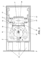
- Figure 2A is a schematic perspective view of one embodiment of a lock system incorporating a locking device according to the invention that is changing from its unlocked state to the begin of the unlocking state, where the levers are not activated, the freewheel is turning and the frame is sliding until it reaches the wards, without the corresponding key being inserted.
- Figure 2B is a schematic perspective similar to that of figure 2A, where a key has been introduced into the lock.
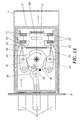
- Figure 3 is a schematic perspective view of one embodiment of a lock system incorporating the locking device according to the invention, where the activated levers are pressing the wards and the frame is distant from the edge of the door and the latches are inside the lock housing.
- Figure 4 is a schematic perspective view of one embodiment of a lock system incorporating the locking device according to the invention, with its state is changing from open to closed, whereby the levers are not activated, the freewheel is rotating in the opposite direction to the previous case and the frame is approaching the edge of the door to block it with the latches by way of an opposite movement to the one of figure 2.
- Figure 5A is a schematic perspective view of the wards carrier support located inside the lock housing of the locking device described in this invention.
- Figure 5B is a schematic perspective view of the wards carrier support with one of the base plates constituting the wards carrier separated in order to appreciate the wards and the corresponding guide protrusions.
- Figure 6 shows a preferred embodiment of a ward.
- Figure 7A is a side section view of the mechanism including the doorknob, freewheel and locking levers of the lock according to the invention.
- Figure 7B is a side section view of the mechanism including the key, wards and wards carrier of the lock according to the invention.
- Referring now to the drawings, wherein a lock in accordance with the invention comprises a rectangular frame (2) that is housed inside the lock housing and is capable of sliding horizontally along the interior of the latter. The frame is produced preferably out of thin plate material and with a width equal to the depth of the lock housing (1) that surrounds the remaining mechanisms such as the driving and blocking system for the wards, as explained later.
- On the vertical side of said rectangular frame (2) located closest to the door edge (P) a number of latches (3) are securely attached to the frame (2) so that they can emerge relative to the door edge acting as closing elements when the frame (2) is horizontally moved to that side, as demonstrated in figures 1 and 2, wherein said latches are introduced into the door jamb.
- The horizontal movement of said frame (2) is realised by way of a freewheel (20) and a connecting rod (21) provided in its interior, one of its ends tilting around a frame stud (27), while the other end of the connecting rod (21) tilts around a stud provided on the periphery of the freewheel (26).
- The freewheel (20) comprises two discs (22, 22') securely mounted in parallel on a central point (25) of the freewheel (20), which is traversed by a shaft (23) that protrudes through the lock housing (1) out to the exterior perpendicularly to the longest side faces of the latter. The shaft (23) incorporates on both ends a doorknob (24), as shown in figure 7A, which can be turned manually by an angle of up to 180°, rotating the freewheel (20) and sliding the connecting rod (21) which, at the same time, drives the frame (2) in either direction.
- The connecting rod (21) is provided with a jog (28) at the point of coincidence with the central point (25) of the freewheel (20) in order to enable the latter to turn in either direction by up to 180°.
- To prevent the frame from sliding without prior introduction of the corresponding key, the frame is provided with a system of wards which are mounted on a ward carrier support (5) which basically comprises two parallel plates (6-6'), as illustrated in the perspective view of figure 5A, which are respectively flush with the two horizontal sides of the frame (2) and one of them being fastened to the bottom of the lock housing (1).
- The wards (4) are brackets mounted superposed on top of each other, as described in figure 6, which comprise a central part (12) in which a rectangular window (7) has been provided to accept the key and which is slightly shifted longitudinally in relation to the centre of the ward body with the purpose detailed later.
- The wards are provided with long neck-like longitudinal extensions defining a head part (8) and a tail part (9) which are fitted between the protruding guides (11-11') provided on the ward carrier (5) to limit the vertical movement of the wards, that is, transversally to the movement of the frame (2), as the central parts of the wards, being wider than the head part (8) and the tail part (9), butt at the protruding guides (11-11') as they move upwards and downwards.
- The two horizontal sides of the frame (2) are provided with internal protruding stops (13-13') which prevent the horizontal movement of the frame (2) if the corresponding key (10) has not been previously inserted, by each butting at the edge or profile of the neck of the head part (8) or the neck of the tail part (9) of one or more wards (4).
- The sides of the frame (2) are resting on the two plates (6-6') of the ward carrier (5), one on the top part and the other on the bottom part, acting as supporting guide for the frame. The protruding stops (13-13') on the frame have the same width as the space existing between the two plates (6-6') of the ward carrier (5), preventing the sides of the frame from sliding sideways.
- The movement of the frame (2) results in the protruding stops (13-13') sweeping over two spaces separated by a distance equal to the length of the wards which, themselves, are all of the same length from head to tail, although their heads and tails are of different lengths between different wards.
- The assembly of wards comprises two types of wards, depending on their position and the mounting order, wherein each group is inverted in relation to the other group, or, in other words, the wards of one group are turned upside-down in relation to the other group, being the assembly of wards formed by an alternating sequence of wards of one and the other group, as illustrated in figure 7B.
- The two plates (6-6') forming part of the ward carrier (5) are provided with a groove (14) that will be opposed to the windows (7) of the wards (4) through which the key is inserted from the exterior of the lock, therefore providing a shape and dimensions adequate for the profile of the key.
- Additionally, the wards (4) incorporate a lateral extension or arm (19) at the upper end of the body (12) and close to the head (8), while, at the opposed end, close to the tail, they are provided with a leg (17) with a function explained later.
- Further, the exterior of the ward carrier support (5) is provided with two levers (16-16') mounted over and under the freewheel (20), respectively, comprising at least one elastic element pulling said levers (16-16') towards each other and leaving each of the free ends of the levers (16-16') resting on the respective arms (19) of each group of wards, that is, the free end of the upper lever (16) pushes against the arms (19) of one group of wards, while the lower lever (16') pushes against the arms (19) of the other group of wards, in this way setting the wards in motion until their bodies (12) butt at the protruding guides (11-11'), leaving the tail ends (9) of all the wards in their most exterior position in relation to the ward carrier (5), while the head parts (8) are left retracted. In this position, corresponding to the maximum turn of the doorknob (24) and determining the closing and opening states of the lock, the windows (7) of all the wards (4) coincide, thus permitting the introduction of the corresponding key.
- The elastic element can be a tension spring (31), mounted so that it connects the ends of the two levers (16-16'), or, alternatively, two independent springs or metal clamps, mounted on the shafts (30-30') of each of the levers (16-16'), respectively.
- The levers (16-16') are movably joined from one of their ends to respective bolts (30') fastened to the bottom of the lock housing (1), enabling the tilting motion of said levers. Each of the levers (16-16') includes in its central part a wheel (32-32') whose radius matches two circular cut-outs (29-29') provided on the freewheel (20) into which they will be firmly housed in the open and closed positions, while the operation of the doorknobs (24) results in the tilting of the levers (16-16') in opposite directions, separating their free ends, acting against the opposing force of the tension spring (31) in such way that during the rotation of the doorknobs (24) from 0° to 180° the wheels turn over the exterior surface of the freewheel (20), while the free ends of the levers (16-16') remain separated from the arms (19) of the wards (4) and, therefore, do not exert any force on them.
- Additionally, a tension spring (18) is mounted on the side legs (17) of each ward (4), which tries to move its respective ward in opposite direction to the driving force of the corresponding lever (16) or (16'), so that when these cease acting on the wards due to the movement of one of the doorknobs (24), the head parts (8) of all the wards (4) remain in their position of maximum movement upwards or downwards, depending on the group they belong to, and finding themselves positioned in the path of the protrusions (13-13') of the frame (2), preventing its horizontal movement and, therefore, the unlocking of the lock. The other end of the spring (18) is attached to the leg (17) of the next ward belonging to the other group, so that each spring (18) will cause the simultaneous movement of the wards belonging to different groups. This position is shown in figure 2A.
- Further, the different lengths of the heads and tails of the wards will result in their ends remaining at different levels.
- For this reason, each ward needs to be moved along a different distance, so that the ends of their heads and tails end up at the same level as the paths of the protrusions (13-13'), allowing the movement of the frame (2).
- To be able to realise this operation simultaneously with all the wards (4), the key (10) is required, which is also an object of this invention.
- The key (10) has a profile (15) such as those shown in detail (d) of figure 7B, preferably cross shaped, wherein the horizontal part is free of any vertical protrusions to provide a tight fit within the slot (14) created by the plates (6-6') of the ward carrier support (5), through which the key (10) is introduced from the exterior of the lock housing (1) and which presents a silhouette that matches its profile (15). Said key (10) includes two wings (33-33'), one directed upwards and the other downwards, which are cut so as to form teeth (34) with different individual depths, depending on the distance required by the corresponding ward (4) when moved by the spring (18) to position it outside of the path of the protrusion (13) or (13').
- The following is a description of the lock operation in regard to its opening or closing.
- We begin with the closed state shown in figure 1, where the levers (16-16') are shown acting on the arms (19) of the wards (4) whose respective windows (7) are perfectly aligned. In this position the key (10) is introduced, as shown in detail (c) of figure 7B, into the slot (14) created by both plates (6-6') of the ward carrier support (5) and the doorknob (24) turned, whereby the wheels (32-32') of the levers (16-16') are forced out of the respective cut-outs (29-29') of the freewheel (20). At this moment the free ends of the levers (16-16') cease to press on the wards (4) which, by means of the spring action (18), are moved to the opposite end to the one they were located.
- In this situation, as shown in figure 2A, the wards (4) which hold the springs (18), slide to the furthest position, at which their head parts (8) and tail parts (9) are arranged in the path of the protrusions (13-13') of the frame (2), thus preventing its movement to enable the opening of the door.
- Otherwise, if the key is introduced as shown in figure 2B, the wards (4) will move, actuated by the spring (18), and butt at the corresponding teeth (34) of the key, said teeth limiting the movement of the wards (4) so that their head parts (8) and tail parts (9) will remain retracted and outside of the reach of the protrusions (13-13'), thus allowing the movement of the frame (2).
- Once the turn of the doorknob (24) has been completed and with it the turn of the discs (22-22') of the freewheel (20) and that of the wheels (32-32') of the levers (16-16'), the cut-outs (29-29') return to their original position, after having passed to the opposite position, so that the free ends of the levers (16-16') will again press onto the wards (4), as demonstrated on figure 3, showing the open state, and the windows (7) of all the wards (4) are coinciding again to allow the extraction of the key (10).
- To close it is not necessary to introduce the key (10) into the slot (14), instead turning the doorknob (24) in opposite direction is sufficient, whereby the wards (4) are moved, driven by the springs (18), positioning their head parts (8) in the most exterior location. Due to the chamfered edge of the head parts, similar to that of the protrusions (13-13'), the movement of the frame (2), caused by the turn of the doorknob (24), will push the interior protrusions (13-13') against the chamfered edges of the guards (4) and force them to retract, so that the protrusions (13-13') of the frame pass over the ends of the heads (8) and tails (9) of the wards, thus enabling the closure of the lock.
Claims (9)
- Quick action door lock comprising a lock housing (1), the lock housing containing the corresponding locking means causing the retraction or extension of a plurality of latches (3) for their insertion into or extraction from the door jamb, respectively, characterised in that it comprises a frame (2) housed in the lock housing to which said latches (3) are securely connected, the frame (2) being able to slide in the interior of the lock housing by operating an external doorknob (24); an assembly of wards arranged transversally relative to the movement of the frame (2) to provide an obstacle to the movement of said frame (2) but capable of retracting to provide free access by the simple introduction of a key (10) without the need to turn that key.
- Quick action door lock as claimed in claim 1, characterised in that the interior of the frame (2) includes a freewheel (20) comprising two parallel disks (22-22') securely attached to a central point (25) that is traversed by a shaft (23) mounted so that it extends to the exterior of the lock housing, incorporating on each end a doorknob (24), said freewheel (20) being movably connected from a point of its periphery to a connecting rod (21), that rod also being movably connected from the opposite end to a stud (27) on the frame (2) so that a 180° turn of the doorknob (24) provides a full displacement of the frame (2) in one or the other direction.
- Quick action door lock as claimed in claim 1, characterised in that the wards comprise a series of metal plates which are superposed in alternative order so that each ward is located in an inverted position in relation to the pervious and next wards in order to accept and act on the key (10) simultaneously from the upper and lower parts of its profile, said wards being all of the same length.
- Quick action door lock as claimed in claim 3, characterised in that the wards are provided with neck-like longitudinal extensions defining a head part (8) and a tail part (9) of different lengths for each ward, apart from those that repeat themselves, in particular so that said necks are housed between the protruding guides (11-11') provided on a ward carrier (5) connected to the lock housing, the protruding guides (11-11') limiting the vertical movement of the wards (4) transversally to the movement of the frame (2) by creating a contact between the central parts of the wards, the latter being wider than the head part (8) and the tail part (9), and the protruding guides (11-11').
- Quick action door lock as claimed in claim 1, characterised in that the key (10) is cross shaped, whereby its horizontal part tightly fits into the slot (14) of the wards carrier support (5) and its vertical part comprises two wings (33-33'), one directed upwards and the other one downwards, said wings being cut in a crenellated pattern (34) with varying depths, onto which the wards (4) are resting.
- Quick action door lock as claimed in claim 1, characterised in that the frame is provided with horizontal sides incorporating interior protrusions (13-13') that butt at the necks of the wards when the frame (2) is moved upon prior introduction of the key (10), the protrusions being separated from one another by a distance equal to the length of the wards (4).
- Quick action door lock as claimed in the previous claims, characterised in that the wards include a central window (7) for the introduction of the key (10) and side legs (17) holding a spring (18) which acts upon the head parts (8) of the wards, moving them so that they are projected over the upper and lower parts of the wards carrier (5) when the key is inserted, this movement being limited by the introduction of the key which aligns all the head parts (8) and tail parts (9) of the wards with the edges of the protrusions (13-13').
- Locking device as claimed in the previous claims, characterised in that the exterior part of the wards carrier (5) includes two levers (16-16') located over and under the freewheel (20), respectively, comprising at least one elastic element (31) pulling said levers (16-16') towards each other and leaving each of the free ends of the levers (16-16') resting on the respective side arms (19) of each group of wards (4), in this way setting the wards in motion until they butt at the protruding guides (11-11') of the frame (2), that position being so that the windows of all the wards are coincident to permit the introduction of the key (10).
- Locking device as claimed in claim 8, characterised in that each of the levers (16-16') is movable from one of its ends on respective bolts (30-30') fastened at the bottom of the lock housing to permit said levers to tilt, providing each of them, approximately in its central, part a wheel (32-32') whose radius matches two circular cut-outs (29-29') provided on the upper or lower part of the freewheel (20) into which they will be firmly housed in the open and closed positions, while the operation of the doorknobs (24) results in the tilting of the levers (16-16'), separating their free ends and enabling the movement of the wards (4) in such way that during the rotation of the doorknobs (24) from 0° to 180° the free ends of the levers (16-16') remain separated from the wards (4).
Applications Claiming Priority (1)
| Application Number | Priority Date | Filing Date | Title |
|---|---|---|---|
| ES200402170A ES2268934A1 (en) | 2004-09-10 | 2004-09-10 | Quick action door lock |
Publications (1)
| Publication Number | Publication Date |
|---|---|
| EP1635013A2 true EP1635013A2 (en) | 2006-03-15 |
Family
ID=35583360
Family Applications (1)
| Application Number | Title | Priority Date | Filing Date |
|---|---|---|---|
| EP20050380155 Withdrawn EP1635013A2 (en) | 2004-09-10 | 2005-07-13 | Quick action door lock |
Country Status (2)
| Country | Link |
|---|---|
| EP (1) | EP1635013A2 (en) |
| ES (1) | ES2268934A1 (en) |
Cited By (4)
| Publication number | Priority date | Publication date | Assignee | Title |
|---|---|---|---|---|
| CN1924265B (en) * | 2006-09-01 | 2010-09-08 | 福建省中福工程建设监理有限公司 | Straight inserting opening counter lock |
| CN1908355B (en) * | 2006-08-11 | 2011-03-23 | 福建省中福工程建设监理有限公司 | Straight inserting opening counter lock |
| WO2011083430A1 (en) * | 2010-01-06 | 2011-07-14 | Ideal Security Ltd. | Bolt assembly with geometrically locked hooks |
| WO2012048350A1 (en) * | 2010-10-11 | 2012-04-19 | Albert Poghosyan | Lock with detachable cylindrical mechanism |
-
2004
- 2004-09-10 ES ES200402170A patent/ES2268934A1/en active Pending
-
2005
- 2005-07-13 EP EP20050380155 patent/EP1635013A2/en not_active Withdrawn
Cited By (4)
| Publication number | Priority date | Publication date | Assignee | Title |
|---|---|---|---|---|
| CN1908355B (en) * | 2006-08-11 | 2011-03-23 | 福建省中福工程建设监理有限公司 | Straight inserting opening counter lock |
| CN1924265B (en) * | 2006-09-01 | 2010-09-08 | 福建省中福工程建设监理有限公司 | Straight inserting opening counter lock |
| WO2011083430A1 (en) * | 2010-01-06 | 2011-07-14 | Ideal Security Ltd. | Bolt assembly with geometrically locked hooks |
| WO2012048350A1 (en) * | 2010-10-11 | 2012-04-19 | Albert Poghosyan | Lock with detachable cylindrical mechanism |
Also Published As
| Publication number | Publication date |
|---|---|
| ES2268934A1 (en) | 2007-03-16 |
Similar Documents
| Publication | Publication Date | Title |
|---|---|---|
| US6810699B2 (en) | Fixed-leaf lock mechanism | |
| US6581991B2 (en) | Automated door latch actuator especially adapted for mortise locks and method corresponding thereto | |
| US5303994A (en) | Drawer interlock | |
| EP0903455B1 (en) | Effraction-resistant device for a lock with flat tumblers | |
| US20100031857A1 (en) | Sequential safe door opening | |
| EP0472774A1 (en) | Locking system | |
| EP1635013A2 (en) | Quick action door lock | |
| US6026665A (en) | Door lock combination chambers | |
| US4929003A (en) | Motorized locking mechanism for a door | |
| US5819567A (en) | Lock system with key trapping | |
| US7261342B2 (en) | Automatically locking window latch | |
| GB2364545A (en) | Lock operable by separate mechanism from either side of casing | |
| US5881498A (en) | Tilt and turn window lock system | |
| CN114412297B (en) | Two-lock one-open locking mechanism and locking device thereof | |
| CA2200815C (en) | Lock adapted to be accommodated within the thickness of an opening panel | |
| CN1138656A (en) | Latch assembly | |
| EP0943761B1 (en) | Lock with flat tumblers and changeable code | |
| EP0144221B1 (en) | Apparatus for locking a closure | |
| CN112796571A (en) | Locking structure of cabinet door leaf | |
| GB2215770A (en) | Improvements in or relating to locks | |
| DE19651609B4 (en) | Lock with latch and latch | |
| GB2134960A (en) | Locking device | |
| CN108590356B (en) | Electromechanical automatic lock | |
| US4907431A (en) | Adjustable lock | |
| CN214740539U (en) | Locking structure of cabinet door leaf |
Legal Events
| Date | Code | Title | Description |
|---|---|---|---|
| PUAI | Public reference made under article 153(3) epc to a published international application that has entered the european phase |
Free format text: ORIGINAL CODE: 0009012 |
|
| AK | Designated contracting states |
Kind code of ref document: A2 Designated state(s): AT BE BG CH CY CZ DE DK EE ES FI FR GB GR HU IE IS IT LI LT LU LV MC NL PL PT RO SE SI SK TR |
|
| AX | Request for extension of the european patent |
Extension state: AL BA HR MK YU |
|
| STAA | Information on the status of an ep patent application or granted ep patent |
Free format text: STATUS: THE APPLICATION IS DEEMED TO BE WITHDRAWN |
|
| 18D | Application deemed to be withdrawn |
Effective date: 20070801 |