EP1634789B1 - Servomoteur comportant un système ameliore de maintien au repos dudit servomoteur - Google Patents
Servomoteur comportant un système ameliore de maintien au repos dudit servomoteur Download PDFInfo
- Publication number
- EP1634789B1 EP1634789B1 EP05018352A EP05018352A EP1634789B1 EP 1634789 B1 EP1634789 B1 EP 1634789B1 EP 05018352 A EP05018352 A EP 05018352A EP 05018352 A EP05018352 A EP 05018352A EP 1634789 B1 EP1634789 B1 EP 1634789B1
- Authority
- EP
- European Patent Office
- Prior art keywords
- skirt
- magnet
- rear wall
- secured
- magnetic permeability
- Prior art date
- Legal status (The legal status is an assumption and is not a legal conclusion. Google has not performed a legal analysis and makes no representation as to the accuracy of the status listed.)
- Expired - Lifetime
Links
Images



Classifications
-
- B—PERFORMING OPERATIONS; TRANSPORTING
- B60—VEHICLES IN GENERAL
- B60T—VEHICLE BRAKE CONTROL SYSTEMS OR PARTS THEREOF; BRAKE CONTROL SYSTEMS OR PARTS THEREOF, IN GENERAL; ARRANGEMENT OF BRAKING ELEMENTS ON VEHICLES IN GENERAL; PORTABLE DEVICES FOR PREVENTING UNWANTED MOVEMENT OF VEHICLES; VEHICLE MODIFICATIONS TO FACILITATE COOLING OF BRAKES
- B60T13/00—Transmitting braking action from initiating means to ultimate brake actuator with power assistance or drive; Brake systems incorporating such transmitting means, e.g. air-pressure brake systems
- B60T13/10—Transmitting braking action from initiating means to ultimate brake actuator with power assistance or drive; Brake systems incorporating such transmitting means, e.g. air-pressure brake systems with fluid assistance, drive, or release
- B60T13/24—Transmitting braking action from initiating means to ultimate brake actuator with power assistance or drive; Brake systems incorporating such transmitting means, e.g. air-pressure brake systems with fluid assistance, drive, or release the fluid being gaseous
- B60T13/46—Vacuum systems
- B60T13/52—Vacuum systems indirect, i.e. vacuum booster units
- B60T13/569—Vacuum systems indirect, i.e. vacuum booster units characterised by piston details, e.g. construction, mounting of diaphragm
-
- B—PERFORMING OPERATIONS; TRANSPORTING
- B60—VEHICLES IN GENERAL
- B60T—VEHICLE BRAKE CONTROL SYSTEMS OR PARTS THEREOF; BRAKE CONTROL SYSTEMS OR PARTS THEREOF, IN GENERAL; ARRANGEMENT OF BRAKING ELEMENTS ON VEHICLES IN GENERAL; PORTABLE DEVICES FOR PREVENTING UNWANTED MOVEMENT OF VEHICLES; VEHICLE MODIFICATIONS TO FACILITATE COOLING OF BRAKES
- B60T13/00—Transmitting braking action from initiating means to ultimate brake actuator with power assistance or drive; Brake systems incorporating such transmitting means, e.g. air-pressure brake systems
- B60T13/10—Transmitting braking action from initiating means to ultimate brake actuator with power assistance or drive; Brake systems incorporating such transmitting means, e.g. air-pressure brake systems with fluid assistance, drive, or release
- B60T13/24—Transmitting braking action from initiating means to ultimate brake actuator with power assistance or drive; Brake systems incorporating such transmitting means, e.g. air-pressure brake systems with fluid assistance, drive, or release the fluid being gaseous
- B60T13/46—Vacuum systems
- B60T13/52—Vacuum systems indirect, i.e. vacuum booster units
- B60T13/567—Vacuum systems indirect, i.e. vacuum booster units characterised by constructional features of the casing or by its strengthening or mounting arrangements
Definitions
- a braking assistance servomotor such as that represented in FIG. 1 essentially comprises an enclosure 10 closed by a front wall 11, a side wall 12 and a rear wall 13. This enclosure comprises two chambers (the front chamber 10av and the rear chamber 10ar) separated by a movable membrane 14.
- a control rod 20 can move towards the front of the vehicle (according to the arrow F1 in Figure 1) when the driver of the vehicle actuates the brake pedal.
- This displacement of the control rod 20 is transmitted to a plunger 21 which actuates assistance means and a piston 22.
- these assistance means comprise a three-way valve whose actuation makes it possible to interrupt the communication between the front chamber 10av and 10ar rear chamber of the booster and put this last chamber to the ambient atmosphere. Since the front chamber 10av is normally under vacuum, and because of the pressure difference between the two chambers, an assisting force is exerted on the movable membrane 14 which separates the two chambers.
- This movable membrane 14 is associated with a skirt 15 of rigid material. Under the effect of the assistance force, the mobile membrane tends to move and causes the skirt 15.
- the skirt 15 itself drives the piston 22 which then moves forward (in the direction of the arrow F1) by acting on a push rod 30 which serves to actuate the master cylinder 31 of the braking circuit.
- the role of the spring 32 is especially to maintain in a stable rest position the piston 22 and the skirt 15. This rest position is such that the skirt is as close as possible to the wall 13. This maintenance is necessary to prevent that in the event of vibrations, for example, the piston 22 and the skirt 15 can not move to the left (in FIG. 1) and trigger an unexpected operation of the servomotor. In addition, because of the low pressure in the front chamber, in the absence of the spring 32, the skirt would be attracted towards the master cylinder.
- the force exerted by the driver on the thrust rod 20 must therefore overcome the effort of maintaining the spring 32.
- the disadvantage is that during the entire braking operation, the spring force 32 remains and the driver must, in addition to the effort required to control the hydraulic braking circuit, continue to overcome the effort of this spring 32.
- the spring force increases in the ferret as the race of the skirt increases.
- the object of the invention is in particular to solve this drawback. It therefore relates to a system that does not require the use of such a spring 32.
- the object of such a system is to increase the efficiency of the braking system when the saturation operating point of the servomotor is reached since the force of the spring 32 does not exist. This improves the performance of the servomotor.
- the invention therefore relates to a servomotor for braking assistance of a vehicle including a skirt and a membrane separating the front chamber of the rear chamber inside the chamber of the booster between a front wall and a rear wall of the enclosure.
- Said skirt is integral with a piston which is intended to communicate the braking forces to the piston of the master cylinder of the braking circuit of the vehicle.
- the piston In the absence of brake control, the piston is pushed back, pushing the skirt near the rear wall of the servomotor.
- the servomotor comprises a magnetic device for magnetically coupling, on the one hand, the skirt or a material element of good magnetic permeability integral with the skirt on the other hand, said rear wall or a material element of good magnetic permeability secured to said rear wall.
- said magnetic device is attached directly or indirectly to the rear wall or to the skirt and can be coupled magnetically respectively, on the one hand, to the skirt or to a material element of good permeability magnetic integral with the skirt or, secondly, said rear wall or an element of good magnetic permeability material integral with said rear wall.
- said magnetic device is a permanent magnet.
- the magnet is secured to the rear wall and, vis-à-vis the magnet, the skirt has no membrane.
- the magnet is secured to the rear wall and, vis-à-vis the magnet, the skirt has a plate of good magnetic permeability.
- the magnet being secured to the skirt, vis-à-vis the magnet, the rear wall comprises a plate of good magnetic permeability.
- the magnet is disposed with one of its polar faces applied to said rear wall or to the skirt or to an element integral with the rear wall or the skirt, and a piece of good magnetic permeability is disposed near the magnet in its magnetic field to serve as a preferential path to the magnetic flux of the magnet.
- the magnet is disposed against said rear wall, or against the skirt, or against an element integral with the rear wall or skirt with its polar faces substantially perpendicular to the plane of the rear wall or the wall. skirt, and in that it comprises two plates of good magnetic permeability plated against said polar faces, the height (h) of these plates parallel to the pole faces being greater than the thickness (e) of the magnet.
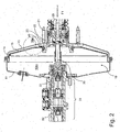
- the design of the booster of FIG. 2 is similar to that of the booster of FIG. 1. It will therefore not be described again the operation of the booster as already described with reference to FIG.
- a magnetic device makes it possible to magnetically couple the rear wall 13 or an element integral with this rear wall to the skirt 15 or to an element integral with this skirt.
- this magnetic device takes the form of a magnet 40 fixed to a fastening element 23 of the booster to which the rear wall 13 is attached or which forms part of the rear wall 13.
- the skirt 15 is supposed to be made of material presenting good magnetic permeability. In a simple manner, the skirt is for example made of sheet steel.
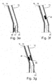
- FIG 3a shows in more detail one embodiment of the magnetic device according to the invention.
- the magnet 40 is fixed on the fixing element 23, for example by gluing. It can also be screwed on the element 23 or flanged.
- the induction of magnetic field induced by the magnet and its position relative to the skirt 15 are calculated such that in the rest position of the booster, that is to say when the driver does not press on his pedal brake, the skirt is attracted by the magnet and is held in a position close to the wall 13.
- this magnetic induction and the The position of the magnet is such that the actuation of the brake pedal makes it easy to move the skirt and to subtract it from the magnetic attraction of the magnet.
- FIG. 3b shows an alternative embodiment of the device of FIG. 3a in which, facing the magnet, a part of the membrane has been removed in order to eliminate the air gap due to the membrane, so that it may be possible to use a valuable magnet weaker, or to obtain a greater magnetic attraction force.
- FIG. 3c shows an alternative embodiment in which a plate 41 of a material of good magnetic permeability attached to the skirt 15 is provided. This is necessary if the skirt 15 is made of a material of low magnetic permeability (plastic duralumin, etc.). It will be this plate that will allow the attraction of the skirt by the magnet. This plate is, for example, iron. It is fixed to the skirt 15 by means of screws for example.
- a plate 41 of a material of good magnetic permeability attached to the skirt 15 is provided. This is necessary if the skirt 15 is made of a material of low magnetic permeability (plastic duralumin, etc.). It will be this plate that will allow the attraction of the skirt by the magnet. This plate is, for example, iron. It is fixed to the skirt 15 by means of screws for example.
- FIGS. 3d and 3e show alternative embodiments in which the magnet 40 is fixed to the skirt 15 opposite the fastening element 23.
- the fastening element 23 is made of a material good magnetic permeability.
- a plate 47 made of a material of good magnetic permeability fixed on the element 23 facing the magnet 40.
- FIGS. 3f and 3g show alternative embodiments in which the magnetic device is located in an area of the wall 13 instead of being located on a wall fixing element.
- the magnet 40 is thus fixed directly to the wall 13.
- the magnet 40 is fixed to the skirt 15 and according to this exemplary variant embodiment, a plate 46 of material good magnetic permeability on the wall 13.
- the magnet 40 is disposed on the wall 13 with its pole 40S in contact with the wall 13.
- the magnet is glued or screwed to the wall 13, or, if the wall 13 is made of material of good magnetic permeability, it can also be maintained at the wall 13 because of its magnetization.
- FIG. 4b there is provided a part 43 of good magnetic permeability making it possible to close the magnetic flux towards the skirt 15.
- the part 43 has substantially the same thickness as the magnet 40.
- the magnet 40 and the part 43 are arranged on a piece 42 of good magnetic permeability which is fixed on the wall 13 and this especially in the case where the wall 13 is not made of material of good magnetic permeability.
- the piece 43 may also be a magnet whose north pole 43N is attached to the plate 42 so that the two magnets 40 and 43 are magnetically in series.
- the magnet is fixed on the wall 13 by one of its lateral faces.
- the exit faces corresponding to the north and south poles 40N and 40S of the magnet are perpendicular to the plane of the wall 13.
- plates 44 and 45 of good magnetic permeability whose height h is greater to the thickness e of the magnet. These plates are maintained by magnetic attraction against the poles 40N and 40S. They allow a channelization of the magnetic flux of the magnet towards the skirt 15.
Landscapes
- Engineering & Computer Science (AREA)
- Transportation (AREA)
- Mechanical Engineering (AREA)
- Braking Systems And Boosters (AREA)
- Valves And Accessory Devices For Braking Systems (AREA)
- Thermistors And Varistors (AREA)
- Compositions Of Oxide Ceramics (AREA)
- Control Of Electric Motors In General (AREA)
Description
- L'invention concerne un servomoteur d'assistance au freinage et plus particulièrement un système de maintien au repos du servomoteur. Un tel servomoteur est décrit dans le document
FR 2834254 - Un servomoteur d'assistance au freinage tel que celui représenté en figure 1 comporte essentiellement une enceinte 10 fermée par une paroi avant 11, une paroi latérale 12 et une paroi arrière 13. Cette enceinte comprend deux chambres (la chambre avant 10av et la chambre arrière 10ar) séparées par une membrane mobile 14.
- Une tige de commande 20 peut se déplacer vers l'avant du véhicule (selon la flèche F1 sur la figure 1) lorsque le conducteur du véhicule actionne la pédale de frein. Ce déplacement de la tige de commande 20 est transmis à un plongeur 21 qui actionne des moyens d'assistance et un piston 22. Généralement, ces moyens d'assistance comprennent une vanne trois voies dont l'actionnement permet d'interrompre la communication entre la chambre avant 10av et la chambre arrière 10ar du servomoteur et de mettre cette dernière chambre à l'atmosphère ambiante. Etant donné que la chambre avant 10av est normalement sous vide, et en raison de la différence de pression entre les deux chambres, une force d'assistance est exercée sur la membrane mobile 14 qui sépare les deux chambres. Cette membrane mobile 14 est associée à une jupe 15 en matériau rigide. Sous l'effet de la force d'assistance, là membrane mobile tend à se déplacer et entraîne la jupe 15.
- La jupe 15 entraîne elle-même le piston 22 qui se déplace alors vers l'avant (selon le sens de la flèche F1) en agissant sur une tige de poussée 30 qui sert à actionner le maître-cylindre 31 du circuit de freinage.
- Lorsque le conducteur du véhicule relâche la pédale de frein le système retourne en position de repos (représentée sur la figure 1) sous l'action du ressort primaire 33 et du ressort secondaire 33' des cylindres primaire et secondaire du maître cylindre, ainsi que sous l'action d'un ressort 32 du servomoteur.
- Le rôle du ressort 32 est surtout de maintenir dans une position de repos stable le piston 22 et la jupe 15. Cette position de repos est telle que la jupe est le plus près possible de la paroi 13. Ce maintien est nécessaire pour éviter qu'en cas de vibrations, par exemple, le piston 22 et la jupe 15 ne puisse pas se déplacer vers la gauche (sur la figure 1) et déclencher un fonctionnement inopiné du servomoteur. De plus, du fait de la basse pression dans la chambre avant, en l'absence du ressort 32, la jupe serait attirée en direction du maître cylindre.
- Lors d'une commande de freinage, l'effort exercée par le conducteur sur la tige de poussée 20 doit donc vaincre l'effort de maintien du ressort 32. Cependant, l'inconvénient est que durant toute l'opération de freinage, l'effort du ressort 32 subsiste et le conducteur doit, outre l'effort nécessaire à la commande du circuit hydraulique de freinage, continuer à vaincre l'effort de ce ressort 32. L'effort du ressort croît au furet à mesure que la course de la jupe augmente.
- L'invention a notamment pour objet de résoudre cet inconvénient. Elle concerne donc un système ne nécessitant pas l'utilisation d'un tel ressort 32.
- L'objet d'un tel système est d'augmenter l'efficacité du système de freinage lorsqu'on atteint le point de fonctionnement de saturation du servomoteur puisque l'effort du ressort 32 n'existe pas. On améliore ainsi les performances du servomoteur.
- L'invention concerne donc un servomoteur d'assistance au freinage d'un véhicule comprenant notamment une jupe et une membrane séparant la chambre avant de la chambre arrière à l'intérieur de l'enceinte du servomoteur entre une paroi avant et une paroi arrière de l'enceinte. Ladite jupe est solidaire d'un piston qui est destiné à communiquer les efforts de freinage au piston du maître cylindre du circuit de freinage du véhicule. En l'absence de commande de freinage, le piston est repoussé en position arrière, repoussant la jupe à proximité de la paroi arrière du servomoteur. Le servomoteur comporte un dispositif magnétique permettant de coupler magnétiquement, d'une part, la jupe ou un élément en matériau de bonne perméabilité magnétique solidaire de la jupe à, d'autre part, ladite paroi arrière ou un élément en matériau de bonne perméabilité magnétique solidaire de ladite paroi arrière.
- Selon une forme de réalisation de l'invention, ledit dispositif magnétique est solidarisé directement ou indirectement à la paroi arrière ou à la jupe et peut se coupler magnétiquement respectivement, d'une part, à la jupe ou à un élément en matériau de bonne perméabilité magnétique solidaire de la jupe ou, d'autre part à ladite paroi arrière ou à un élément en matériau de bonne perméabilité magnétique solidaire de ladite paroi arrière.
- Avantageusement, ledit dispositif magnétique est un aimant permanent.
- Selon une forme de réalisation de l'invention, l'aimant est solidarisé à la paroi arrière et, en vis-à-vis de l'aimant, la jupe ne comporte pas de membrane.
- Selon une autre forme de réalisation, l'aimant est solidarisé à la paroi arrière et, en vis-à-vis de l'aimant, la jupe comporte une plaque de bonne perméabilité magnétique.
- Ou bien, l'aimant étant solidarisé à la jupe, en vis-à-vis de l'aimant, la paroi arrière comporte une plaque de bonne perméabilité magnétique.
- Selon une variante de réalisation de l'invention, l'aimant est disposé avec l'une de ses faces polaires appliquée à ladite paroi arrière ou à la jupe ou à un élément solidaire de la paroi arrière ou de la jupe, et une pièce de bonne perméabilité magnétique est disposée à proximité de l'aimant dans son champ magnétique pour servir de chemin préférentiel au flux magnétique de l'aimant.
- Selon une autre variante de réalisation, l'aimant est disposé contre ladite paroi arrière, ou contre la jupe, ou contre un élément solidaire de la paroi arrière ou de la jupe avec ses faces polaires sensiblement perpendiculaires au plan de la paroi arrière ou de la jupe, et en ce qu'il comporte deux plaques de bonne perméabilité magnétique plaquée contre les dites faces polaires, la hauteur (h) de ces plaques parallèlement aux faces polaires étant supérieure à l'épaisseur (e) de l'aimant.
- Les différents objets caractéristiques de l'invention apparaîtront plus clairement dans la description qui va suivre et dans les figures annexées qui représentent:
- la figure 1, un exemple de servomoteur d'assistance au freinage de véhicule automobile connu dans la technique,
- la figure 2, un exemple de réalisation selon l'invention d'un système de maintien au repos d'un servomoteur d'assistance au freinage,
- les figures 3a à 3g, différents exemples de réalisation selon l'invention d'un dispositif de maintien au repos de la jupe du servomoteur,
- les figures 4a à 4c, différents modes de réalisation selon l'invention des aimants des figures 3a à 3g.
- En se reportant à la figure 2, on va donc décrire un exemple de réalisation d'un système de maintien au repos d'un servomoteur d'assistance au freinage d'un véhicule automobile.
- La conception du servomoteur de la figure 2 est similaire à celle du servomoteur de la figure 1. On ne décrira donc pas à nouveau le fonctionnement du servomoteur tel qu'il a été déjà décrit en relation avec la figure 1.
- Selon l'invention, un dispositif magnétique permet de coupler magnétiquement la paroi arrière 13 ou un élément solidaire de cette paroi arrière à la jupe 15 ou à un élément solidaire de cette jupe. Sur la figure 2, ce dispositif magnétique prend la forme d'un aimant 40 fixé à un élément de fixation 23 du servomoteur auquel est fixée la paroi arrière 13 ou faisant partie de la paroi arrière 13. La jupe 15 est supposée être en matériau présentant une bonne perméabilité magnétique. De façon simple, la jupe est par exemple en tôle d'acier.
- La figure 3a représente de façon plus détaillée une forme de réalisation du dispositif magnétique selon l'invention. L'aimant 40 est fixé sur l'élément de fixation 23 par exemple par collage. Il peut être également vissé sur l'élément 23 ou bridé.
- L'induction de champ magnétique induite par l'aimant et sa position par rapport à la jupe 15 sont calculées de telle façon qu'en position de repos du servomoteur c'est-à-dire lorsque le conducteur n'appuie pas sur sa pédale de frein, la jupe est attirée par l'aimant et est maintenue dans une position proche de la paroi 13. Par contre, cette induction magnétique et la position de l'aimant sont telles que l'actionnement de la pédale de frein permette aisément de déplacer la jupe et de la soustraire à l'attraction magnétique de l'aimant. Lorsque la jupe n'est plus ou quasiment plus sous l'influence du champ magnétique de l'aimant, l'effort exercé par le conducteur du véhicule n'a donc plus à vaincre la force d'attraction résultant de l'induction du champ magnétique.
- La figure 3b représente une variante de réalisation du dispositif de la figure 3a dans laquelle en regard de l'aimant, une partie de la membrane a été supprimée pour supprimer l'entrefer dû à la membrane de façon éventuellement à pouvoir utiliser un aimant de valeur plus faible ou bien, pour obtenir une force d'attraction magnétique plus importante.
- Sur la figure 3c, on a représenté une variante de réalisation dans laquelle on a prévu une plaque 41 d'un matériau de bonne perméabilité magnétique fixée à la jupe 15. Cela est nécessaire si la jupe 15 est en matériau de faible perméabilité magnétique (plastique, duralumin, etc.). Ce sera donc cette plaque qui permettra l'attraction de la jupe par l'aimant. Cette plaque est, par exemple, en fer. Elle est fixée à la jupe 15 à l'aide de vis par exemple.
- Les figures 3d et 3e représentent des variantes de réalisation dans lesquelles l'aimant 40 est fixé à la jupe 15 en regard de l'élément de fixation 23. Dans le mode réalisation de la figure 3d, l'élément de fixation 23 est en matériau de bonne perméabilité magnétique. Dans le mode réalisation de la figure 3e, on a prévu une plaque 47 en matériau de bonne perméabilité magnétique fixée sur l'élément 23 en regard de l'aimant 40.
- Les figures 3f et 3g représentent des variantes de réalisation dans lesquelles le dispositif magnétique est localisé dans une zone de la paroi 13 au lieu d'être localisé sur un élément de fixation de la paroi. Sur la figure 3f, l'aimant 40 est donc fixé directement à la paroi 13. Sur la figure 3g, l'aimant 40 est fixé à la jupe 15 et selon cet exemple de variante de réalisation, on a prévu une plaque 46 en matériau de bonne perméabilité magnétique sur la paroi 13.
- En se reportant aux figures 4a à 4c, on va décrire différents modes de réalisation de l'aimant 40.
- Sur la figure 4a, l'aimant 40 est disposé sur la paroi 13 avec son pôle 40S en contact avec la paroi 13. L'aimant est collé ou fixé par vis à la paroi 13, ou bien, si la paroi 13 est en matériau de bonne perméabilité magnétique, il peut également se maintenir à la paroi 13 en raison de son aimantation.
- Sur la fïgure 4b, on a prévu une pièce 43 de bonne perméabilité magnétique permettant de refermer le flux magnétique vers la jupe 15. La pièce 43 a sensiblement la même épaisseur que l'aimant 40. L'aimant 40 et la pièce 43 sont disposés sur une pièce 42 de bonne perméabilité magnétique qui est fixée sur la paroi 13 et cela notamment dans le cas ou la paroi 13 n'est pas en matériau de bonne perméabilité magnétique.
- Selon une variante de réalisation, la pièce 43 peut être également un aimant dont le pôle nord 43N est accolé à la plaque 42 de façon que les deux aimants 40 et 43 soient magnétiquement en série.
- Sur la figure 4c, l'aimant est fixé sur la paroi 13 par l'une de ses faces latérales. Les faces de sortie correspondant aux pôles nord et sud 40N et 40S de l'aimant sont perpendiculaires au plan de la paroi 13. En bouts des pôles 40N et 40S sont prévues des plaques 44 et 45 de bonne perméabilité magnétique dont la hauteur h est supérieure à l'épaisseur e de l'aimant. Ces plaques se maintiennent par attraction magnétique contre les pôles 40N et 40S. Elles permettent une canalisation du flux magnétique de l'aimant vers la jupe 15.
Claims (8)
- Servomoteur d'assistance au freinage d'un véhicule comprenant notamment une jupe (15) et une membrane (14) séparant la chambre avant (10av) de la chambre arrière (10ar) à l'intérieur dé l'enceinte (10) du servomoteur entre une paroi avant (11) et une paroi arrière (13) de l'enceinte, ladite jupe étant solidaire d'un piston (22) qui est destiné à communiquer les efforts de freinage au piston du maître cylindre (31) du circuit de freinage du véhicule et qui, en l'absence de commandé de freinage, est repoussé en position arrière, repoussant la jupe (15) à proximité de la paroi arrière (13) du servomoteur, caractérisé en ce qu'il comporte un dispositif magnétique (40) permettant de coupler magnétiquement, d'une part, la jupe (15) ou un élément en- matériau de bonne perméabilité magnétique solidaire de la jupe (15) à, d'autre part, ladite paroi arrière (13) ou un élément en matériau de bonne perméabilité magnétique solidaire de ladite paroi arrière.
- Servomoteur d'assistance au freinage, selon la revendication 1, caractérisé en ce que ledit dispositif magnétique est solidarisé directement ou indirectement à la paroi arrière (13) ou à la jupe (15) et qu'il peut se coupler magnétiquement respectivement, d'une part, à la jupe (15) ou à un élément en matériau de bonne perméabilité magnétique solidaire de la jupe (15) ou, d'autre part à ladite paroi arrière (13) ou à un élément en matériau de bonne perméabilité magnétique solidaire de ladite paroi arrière.
- Servomoteur d'assistance au freinage selon la revendication 2, caractérisé en ce que ledit dispositif magnétique est un aimant permanent (40).
- Servomoteur d'assistance au freinage selon la revendication 3, caractérisé en ce que, l'aimant. (40) étant solidarisé à la paroi arrière (13), en vis-à-vis de l'aimant la jupe ne comporte pas de membrane.
- Servomoteur d'assistance au freinage selon la revendication 3, caractérisé en ce que, l'aimant (40) étant solidarisé à la paroi arrière (13), en vis-à-vis de l'aimant (40), la jupe : comporte une plaque (41) de bonne perméabilité magnétique.
- Servomoteur d'assistance au freinage selon la revendication 3, caractérisé en ce que l'aimant (40) étant solidarisé à la jupe. (15), en vis-à-vis de l'aimant (40), la paroi arrière comporte une plaque (46, 47) de bonne perméabilité magnétique.
- Servomoteur d'assistance au freinage selon la revendication 3, caractérisé en ce que l'aimant (40) est disposé avec l'une de ses faces polaires (40S) appliquée à ladite paroi arrière (13) ou à la jupe (15) ou à un élément solidaire, de la paroi arrière ou de la jupe, et en ce qu' il comporte une pièce (43) de bonne perméabilité magnétique disposée à proximité de l'aimant dans son champ magnétique pour servir de chemin préférentiel au flux magnétique de l'aimant.
- Servomoteur d'assistance au freinage selon la revendication 1, caractérisé en ce que l'aimant est disposé contre ladite paroi arrière ou contre la jupe, ou contre un élément solidaire de la paroi arrière ou de la jupe avec ses faces polaires (40N et 40S) sensiblement perpendiculaires au plan de la paroi arrière ou de la jupe, et en ce qu'il comporte deux plaques (44, 45) de bonne perméabilité magnétique plaquée contre les dites faces polaires (40N et 40S), la hauteur (h) de ces plaques parallèlement aux faces polaires étant supérieure à l'épaisseur (e) de l'aimant.
Priority Applications (1)
| Application Number | Priority Date | Filing Date | Title |
|---|---|---|---|
| PL05018352T PL1634789T3 (pl) | 2004-09-08 | 2005-08-24 | Siłownik zawierający ulepszony system utrzymania siłownika w stanie spoczynku |
Applications Claiming Priority (1)
| Application Number | Priority Date | Filing Date | Title |
|---|---|---|---|
| FR0409543A FR2874882B1 (fr) | 2004-09-08 | 2004-09-08 | Servomoteur comportant un systeme ameliore de maintien au repos dudit servomoteur |
Publications (2)
| Publication Number | Publication Date |
|---|---|
| EP1634789A1 EP1634789A1 (fr) | 2006-03-15 |
| EP1634789B1 true EP1634789B1 (fr) | 2007-08-01 |
Family
ID=34948996
Family Applications (1)
| Application Number | Title | Priority Date | Filing Date |
|---|---|---|---|
| EP05018352A Expired - Lifetime EP1634789B1 (fr) | 2004-09-08 | 2005-08-24 | Servomoteur comportant un système ameliore de maintien au repos dudit servomoteur |
Country Status (7)
| Country | Link |
|---|---|
| EP (1) | EP1634789B1 (fr) |
| AT (1) | ATE368599T1 (fr) |
| DE (1) | DE602005001824T8 (fr) |
| ES (1) | ES2289629T3 (fr) |
| FR (1) | FR2874882B1 (fr) |
| PL (1) | PL1634789T3 (fr) |
| PT (1) | PT1634789E (fr) |
Families Citing this family (2)
| Publication number | Priority date | Publication date | Assignee | Title |
|---|---|---|---|---|
| RU2373087C2 (ru) * | 2007-09-26 | 2009-11-20 | Сергей Николаевич Шуклинов | Крепление главного тормозного цилиндра к вакуумному усилителю |
| RU2373086C2 (ru) * | 2007-09-26 | 2009-11-20 | Сергей Николаевич Шуклинов | Клапанный узел вакуумного усилителя |
Family Cites Families (3)
| Publication number | Priority date | Publication date | Assignee | Title |
|---|---|---|---|---|
| DE4030682A1 (de) * | 1990-09-28 | 1992-04-02 | Kugelfischer G Schaefer & Co | Bremskraftverstaerker |
| FR2834254B1 (fr) * | 2001-12-31 | 2004-06-25 | Bosch Gmbh Robert | Dispositif de commande des feux de freinage dans un vehicule automobile |
| DE10323655A1 (de) * | 2002-08-27 | 2004-04-01 | Continental Teves Ag & Co. Ohg | Bremskraftverstärker |
-
2004
- 2004-09-08 FR FR0409543A patent/FR2874882B1/fr not_active Expired - Fee Related
-
2005
- 2005-08-24 DE DE602005001824T patent/DE602005001824T8/de active Active
- 2005-08-24 ES ES05018352T patent/ES2289629T3/es not_active Expired - Lifetime
- 2005-08-24 AT AT05018352T patent/ATE368599T1/de not_active IP Right Cessation
- 2005-08-24 EP EP05018352A patent/EP1634789B1/fr not_active Expired - Lifetime
- 2005-08-24 PT PT05018352T patent/PT1634789E/pt unknown
- 2005-08-24 PL PL05018352T patent/PL1634789T3/pl unknown
Also Published As
| Publication number | Publication date |
|---|---|
| ATE368599T1 (de) | 2007-08-15 |
| EP1634789A1 (fr) | 2006-03-15 |
| DE602005001824D1 (de) | 2007-09-13 |
| PL1634789T3 (pl) | 2007-10-31 |
| DE602005001824T8 (de) | 2008-07-24 |
| FR2874882A1 (fr) | 2006-03-10 |
| PT1634789E (pt) | 2007-09-11 |
| DE602005001824T2 (de) | 2008-04-17 |
| ES2289629T3 (es) | 2008-02-01 |
| FR2874882B1 (fr) | 2006-12-15 |
Similar Documents
| Publication | Publication Date | Title |
|---|---|---|
| FR2489035A3 (fr) | Dispositif electromagnetique a faible constante de temps, avec element piezo-electrique | |
| FR2648772A1 (fr) | Amplificateur de force de freinage a depression pour systeme de freinage a regulation du glissement | |
| FR2532084A1 (fr) | Cle d'arret pour plongeur de valve de servomoteur d'assistance et servomoteur d'assistance equipe d'une telle cle | |
| EP1634789A1 (fr) | Servomoteur comportant un système ameliore de maintien au repos dudit servomoteur | |
| EP1930219A1 (fr) | Servomoteur pneumatique d'assistance au freinage comportant un capteur d'effort | |
| EP1561914B1 (fr) | Perfectionnements apportés à un actionneur électromécanique de soupape de moteur à combustion interne | |
| WO1999062749A1 (fr) | Servomoteur pneumatique a disque de reaction flottant et a reaction dynamiquement annulable | |
| FR2885108A1 (fr) | Dispositif maitre cylindre pour vehicule automobile | |
| FR2940947A1 (fr) | Simulateur pour servofrein de vehicule comprenant une piece intermediaire | |
| EP2253521B1 (fr) | Servofrein à électrovalve | |
| FR2589416A1 (fr) | Generateur de pression de freinage | |
| EP1900584B1 (fr) | Servomoteur d'assistance au freinage | |
| EP2058196B1 (fr) | Palpeur pour servomoteur d'assistance au freinage | |
| FR2902735A1 (fr) | Amplificateur de freinage | |
| EP2178728B1 (fr) | Servomoteur d'assistance au freinage pour systeme de freinage de vehicule automobile | |
| FR2834253A1 (fr) | Dispositif de commande des feux de freinage sur un vehicule automobile | |
| FR2848936A1 (fr) | Maitre-cylindre comportant un dispositif de detection d'actionnement d'un systeme de freinage et vehicule comportant un tel maitre-cylindre | |
| EP1053155B1 (fr) | Servomoteur pneumatique a reaction mecanique dynamiquement variable | |
| FR2873975A1 (fr) | Servomoteur d'assistance au freinage | |
| EP1497839A1 (fr) | Actionneur electromagnetique a aimant permanent | |
| FR2711104A1 (fr) | Système de freinage assisté à commande automatique et à réserve contrôlée. | |
| FR2905102A1 (fr) | Fixation d'un maitre cylindre de frein. | |
| FR2774346A1 (fr) | Dispositif de freinage a commande electrique assistee | |
| FR2919251A1 (fr) | Dispositif detecteur de freinage et de commande de feux arriere d'un vehicule. | |
| FR2869375A1 (fr) | Dispositif de couplage, servomoteur muni d'un tel dispositif et ensemble comportant un tel servomoteur |
Legal Events
| Date | Code | Title | Description |
|---|---|---|---|
| PUAI | Public reference made under article 153(3) epc to a published international application that has entered the european phase |
Free format text: ORIGINAL CODE: 0009012 |
|
| AK | Designated contracting states |
Kind code of ref document: A1 Designated state(s): AT BE BG CH CY CZ DE DK EE ES FI FR GB GR HU IE IS IT LI LT LU LV MC NL PL PT RO SE SI SK TR |
|
| AX | Request for extension of the european patent |
Extension state: AL BA HR MK YU |
|
| 17P | Request for examination filed |
Effective date: 20060915 |
|
| AKX | Designation fees paid |
Designated state(s): AT BE BG CH CY CZ DE DK EE ES FI FR GB GR HU IE IS IT LI LT LU LV MC NL PL PT RO SE SI SK TR |
|
| GRAP | Despatch of communication of intention to grant a patent |
Free format text: ORIGINAL CODE: EPIDOSNIGR1 |
|
| GRAS | Grant fee paid |
Free format text: ORIGINAL CODE: EPIDOSNIGR3 |
|
| GRAA | (expected) grant |
Free format text: ORIGINAL CODE: 0009210 |
|
| AK | Designated contracting states |
Kind code of ref document: B1 Designated state(s): AT BE BG CH CY CZ DE DK EE ES FI FR GB GR HU IE IS IT LI LT LU LV MC NL PL PT RO SE SI SK TR |
|
| REG | Reference to a national code |
Ref country code: GB Ref legal event code: FG4D Free format text: NOT ENGLISH |
|
| REG | Reference to a national code |
Ref country code: CH Ref legal event code: EP |
|
| REG | Reference to a national code |
Ref country code: IE Ref legal event code: FG4D Free format text: LANGUAGE OF EP DOCUMENT: FRENCH |
|
| REG | Reference to a national code |
Ref country code: PT Ref legal event code: SC4A Free format text: AVAILABILITY OF NATIONAL TRANSLATION Effective date: 20070829 |
|
| REF | Corresponds to: |
Ref document number: 602005001824 Country of ref document: DE Date of ref document: 20070913 Kind code of ref document: P |
|
| GBT | Gb: translation of ep patent filed (gb section 77(6)(a)/1977) |
Effective date: 20070905 |
|
| REG | Reference to a national code |
Ref country code: PL Ref legal event code: T3 |
|
| PG25 | Lapsed in a contracting state [announced via postgrant information from national office to epo] |
Ref country code: BG Free format text: LAPSE BECAUSE OF FAILURE TO SUBMIT A TRANSLATION OF THE DESCRIPTION OR TO PAY THE FEE WITHIN THE PRESCRIBED TIME-LIMIT Effective date: 20071101 Ref country code: LT Free format text: LAPSE BECAUSE OF FAILURE TO SUBMIT A TRANSLATION OF THE DESCRIPTION OR TO PAY THE FEE WITHIN THE PRESCRIBED TIME-LIMIT Effective date: 20070801 Ref country code: IS Free format text: LAPSE BECAUSE OF FAILURE TO SUBMIT A TRANSLATION OF THE DESCRIPTION OR TO PAY THE FEE WITHIN THE PRESCRIBED TIME-LIMIT Effective date: 20071201 Ref country code: FI Free format text: LAPSE BECAUSE OF FAILURE TO SUBMIT A TRANSLATION OF THE DESCRIPTION OR TO PAY THE FEE WITHIN THE PRESCRIBED TIME-LIMIT Effective date: 20070801 |
|
| REG | Reference to a national code |
Ref country code: ES Ref legal event code: FG2A Ref document number: 2289629 Country of ref document: ES Kind code of ref document: T3 |
|
| BERE | Be: lapsed |
Owner name: ROBERT BOSCH G.M.B.H. Effective date: 20070831 |
|
| PG25 | Lapsed in a contracting state [announced via postgrant information from national office to epo] |
Ref country code: AT Free format text: LAPSE BECAUSE OF FAILURE TO SUBMIT A TRANSLATION OF THE DESCRIPTION OR TO PAY THE FEE WITHIN THE PRESCRIBED TIME-LIMIT Effective date: 20070801 |
|
| REG | Reference to a national code |
Ref country code: IE Ref legal event code: FD4D |
|
| PG25 | Lapsed in a contracting state [announced via postgrant information from national office to epo] |
Ref country code: LV Free format text: LAPSE BECAUSE OF FAILURE TO SUBMIT A TRANSLATION OF THE DESCRIPTION OR TO PAY THE FEE WITHIN THE PRESCRIBED TIME-LIMIT Effective date: 20070801 |
|
| PG25 | Lapsed in a contracting state [announced via postgrant information from national office to epo] |
Ref country code: GR Free format text: LAPSE BECAUSE OF FAILURE TO SUBMIT A TRANSLATION OF THE DESCRIPTION OR TO PAY THE FEE WITHIN THE PRESCRIBED TIME-LIMIT Effective date: 20071102 Ref country code: MC Free format text: LAPSE BECAUSE OF NON-PAYMENT OF DUE FEES Effective date: 20070831 Ref country code: DK Free format text: LAPSE BECAUSE OF FAILURE TO SUBMIT A TRANSLATION OF THE DESCRIPTION OR TO PAY THE FEE WITHIN THE PRESCRIBED TIME-LIMIT Effective date: 20070801 |
|
| PG25 | Lapsed in a contracting state [announced via postgrant information from national office to epo] |
Ref country code: SK Free format text: LAPSE BECAUSE OF FAILURE TO SUBMIT A TRANSLATION OF THE DESCRIPTION OR TO PAY THE FEE WITHIN THE PRESCRIBED TIME-LIMIT Effective date: 20070801 Ref country code: IE Free format text: LAPSE BECAUSE OF FAILURE TO SUBMIT A TRANSLATION OF THE DESCRIPTION OR TO PAY THE FEE WITHIN THE PRESCRIBED TIME-LIMIT Effective date: 20070801 Ref country code: CZ Free format text: LAPSE BECAUSE OF FAILURE TO SUBMIT A TRANSLATION OF THE DESCRIPTION OR TO PAY THE FEE WITHIN THE PRESCRIBED TIME-LIMIT Effective date: 20070801 |
|
| PLBE | No opposition filed within time limit |
Free format text: ORIGINAL CODE: 0009261 |
|
| STAA | Information on the status of an ep patent application or granted ep patent |
Free format text: STATUS: NO OPPOSITION FILED WITHIN TIME LIMIT |
|
| PG25 | Lapsed in a contracting state [announced via postgrant information from national office to epo] |
Ref country code: SE Free format text: LAPSE BECAUSE OF FAILURE TO SUBMIT A TRANSLATION OF THE DESCRIPTION OR TO PAY THE FEE WITHIN THE PRESCRIBED TIME-LIMIT Effective date: 20071101 Ref country code: RO Free format text: LAPSE BECAUSE OF FAILURE TO SUBMIT A TRANSLATION OF THE DESCRIPTION OR TO PAY THE FEE WITHIN THE PRESCRIBED TIME-LIMIT Effective date: 20070801 |
|
| 26N | No opposition filed |
Effective date: 20080506 |
|
| PG25 | Lapsed in a contracting state [announced via postgrant information from national office to epo] |
Ref country code: BE Free format text: LAPSE BECAUSE OF NON-PAYMENT OF DUE FEES Effective date: 20070831 |
|
| PG25 | Lapsed in a contracting state [announced via postgrant information from national office to epo] |
Ref country code: EE Free format text: LAPSE BECAUSE OF FAILURE TO SUBMIT A TRANSLATION OF THE DESCRIPTION OR TO PAY THE FEE WITHIN THE PRESCRIBED TIME-LIMIT Effective date: 20070801 |
|
| PG25 | Lapsed in a contracting state [announced via postgrant information from national office to epo] |
Ref country code: SI Free format text: LAPSE BECAUSE OF FAILURE TO SUBMIT A TRANSLATION OF THE DESCRIPTION OR TO PAY THE FEE WITHIN THE PRESCRIBED TIME-LIMIT Effective date: 20070801 |
|
| PG25 | Lapsed in a contracting state [announced via postgrant information from national office to epo] |
Ref country code: CY Free format text: LAPSE BECAUSE OF FAILURE TO SUBMIT A TRANSLATION OF THE DESCRIPTION OR TO PAY THE FEE WITHIN THE PRESCRIBED TIME-LIMIT Effective date: 20070801 |
|
| PG25 | Lapsed in a contracting state [announced via postgrant information from national office to epo] |
Ref country code: LU Free format text: LAPSE BECAUSE OF NON-PAYMENT OF DUE FEES Effective date: 20070824 |
|
| PG25 | Lapsed in a contracting state [announced via postgrant information from national office to epo] |
Ref country code: HU Free format text: LAPSE BECAUSE OF FAILURE TO SUBMIT A TRANSLATION OF THE DESCRIPTION OR TO PAY THE FEE WITHIN THE PRESCRIBED TIME-LIMIT Effective date: 20080202 |
|
| REG | Reference to a national code |
Ref country code: CH Ref legal event code: PL |
|
| PG25 | Lapsed in a contracting state [announced via postgrant information from national office to epo] |
Ref country code: CH Free format text: LAPSE BECAUSE OF NON-PAYMENT OF DUE FEES Effective date: 20090831 Ref country code: LI Free format text: LAPSE BECAUSE OF NON-PAYMENT OF DUE FEES Effective date: 20090831 |
|
| PGFP | Annual fee paid to national office [announced via postgrant information from national office to epo] |
Ref country code: TR Payment date: 20130819 Year of fee payment: 9 Ref country code: FR Payment date: 20130820 Year of fee payment: 9 |
|
| PGFP | Annual fee paid to national office [announced via postgrant information from national office to epo] |
Ref country code: NL Payment date: 20140821 Year of fee payment: 10 |
|
| PGFP | Annual fee paid to national office [announced via postgrant information from national office to epo] |
Ref country code: PT Payment date: 20140224 Year of fee payment: 10 |
|
| REG | Reference to a national code |
Ref country code: FR Ref legal event code: ST Effective date: 20150430 |
|
| PG25 | Lapsed in a contracting state [announced via postgrant information from national office to epo] |
Ref country code: FR Free format text: LAPSE BECAUSE OF NON-PAYMENT OF DUE FEES Effective date: 20140901 |
|
| PGFP | Annual fee paid to national office [announced via postgrant information from national office to epo] |
Ref country code: ES Payment date: 20150825 Year of fee payment: 11 Ref country code: GB Payment date: 20150824 Year of fee payment: 11 |
|
| PGFP | Annual fee paid to national office [announced via postgrant information from national office to epo] |
Ref country code: PL Payment date: 20150811 Year of fee payment: 11 |
|
| PGFP | Annual fee paid to national office [announced via postgrant information from national office to epo] |
Ref country code: IT Payment date: 20150827 Year of fee payment: 11 |
|
| REG | Reference to a national code |
Ref country code: PT Ref legal event code: MM4A Free format text: LAPSE DUE TO NON-PAYMENT OF FEES Effective date: 20160224 |
|
| REG | Reference to a national code |
Ref country code: NL Ref legal event code: MM Effective date: 20150901 |
|
| PG25 | Lapsed in a contracting state [announced via postgrant information from national office to epo] |
Ref country code: PT Free format text: LAPSE BECAUSE OF NON-PAYMENT OF DUE FEES Effective date: 20160224 |
|
| PG25 | Lapsed in a contracting state [announced via postgrant information from national office to epo] |
Ref country code: NL Free format text: LAPSE BECAUSE OF NON-PAYMENT OF DUE FEES Effective date: 20150901 |
|
| PGFP | Annual fee paid to national office [announced via postgrant information from national office to epo] |
Ref country code: DE Payment date: 20161027 Year of fee payment: 12 |
|
| GBPC | Gb: european patent ceased through non-payment of renewal fee |
Effective date: 20160824 |
|
| PG25 | Lapsed in a contracting state [announced via postgrant information from national office to epo] |
Ref country code: GB Free format text: LAPSE BECAUSE OF NON-PAYMENT OF DUE FEES Effective date: 20160824 |
|
| PG25 | Lapsed in a contracting state [announced via postgrant information from national office to epo] |
Ref country code: TR Free format text: LAPSE BECAUSE OF NON-PAYMENT OF DUE FEES Effective date: 20150824 Ref country code: IT Free format text: LAPSE BECAUSE OF NON-PAYMENT OF DUE FEES Effective date: 20160824 |
|
| PG25 | Lapsed in a contracting state [announced via postgrant information from national office to epo] |
Ref country code: PL Free format text: LAPSE BECAUSE OF NON-PAYMENT OF DUE FEES Effective date: 20160824 |
|
| REG | Reference to a national code |
Ref country code: DE Ref legal event code: R119 Ref document number: 602005001824 Country of ref document: DE |
|
| PG25 | Lapsed in a contracting state [announced via postgrant information from national office to epo] |
Ref country code: ES Free format text: LAPSE BECAUSE OF NON-PAYMENT OF DUE FEES Effective date: 20160825 |
|
| REG | Reference to a national code |
Ref country code: ES Ref legal event code: FD2A Effective date: 20180627 |
|
| PG25 | Lapsed in a contracting state [announced via postgrant information from national office to epo] |
Ref country code: DE Free format text: LAPSE BECAUSE OF NON-PAYMENT OF DUE FEES Effective date: 20180301 |