EP1634779A1 - Inflator - Google Patents
Inflator Download PDFInfo
- Publication number
- EP1634779A1 EP1634779A1 EP04734351A EP04734351A EP1634779A1 EP 1634779 A1 EP1634779 A1 EP 1634779A1 EP 04734351 A EP04734351 A EP 04734351A EP 04734351 A EP04734351 A EP 04734351A EP 1634779 A1 EP1634779 A1 EP 1634779A1
- Authority
- EP
- European Patent Office
- Prior art keywords
- inflator
- gas
- air bag
- inflator housing
- housing
- Prior art date
- Legal status (The legal status is an assumption and is not a legal conclusion. Google has not performed a legal analysis and makes no representation as to the accuracy of the status listed.)
- Withdrawn
Links
Images
Classifications
-
- B—PERFORMING OPERATIONS; TRANSPORTING
- B60—VEHICLES IN GENERAL
- B60R—VEHICLES, VEHICLE FITTINGS, OR VEHICLE PARTS, NOT OTHERWISE PROVIDED FOR
- B60R21/00—Arrangements or fittings on vehicles for protecting or preventing injuries to occupants or pedestrians in case of accidents or other traffic risks
- B60R21/02—Occupant safety arrangements or fittings, e.g. crash pads
- B60R21/16—Inflatable occupant restraints or confinements designed to inflate upon impact or impending impact, e.g. air bags
- B60R21/26—Inflatable occupant restraints or confinements designed to inflate upon impact or impending impact, e.g. air bags characterised by the inflation fluid source or means to control inflation fluid flow
- B60R21/264—Inflatable occupant restraints or confinements designed to inflate upon impact or impending impact, e.g. air bags characterised by the inflation fluid source or means to control inflation fluid flow using instantaneous generation of gas, e.g. pyrotechnic
- B60R21/2644—Inflatable occupant restraints or confinements designed to inflate upon impact or impending impact, e.g. air bags characterised by the inflation fluid source or means to control inflation fluid flow using instantaneous generation of gas, e.g. pyrotechnic using only solid reacting substances, e.g. pellets, powder
-
- B—PERFORMING OPERATIONS; TRANSPORTING
- B60—VEHICLES IN GENERAL
- B60R—VEHICLES, VEHICLE FITTINGS, OR VEHICLE PARTS, NOT OTHERWISE PROVIDED FOR
- B60R21/00—Arrangements or fittings on vehicles for protecting or preventing injuries to occupants or pedestrians in case of accidents or other traffic risks
- B60R21/02—Occupant safety arrangements or fittings, e.g. crash pads
- B60R21/16—Inflatable occupant restraints or confinements designed to inflate upon impact or impending impact, e.g. air bags
- B60R21/26—Inflatable occupant restraints or confinements designed to inflate upon impact or impending impact, e.g. air bags characterised by the inflation fluid source or means to control inflation fluid flow
- B60R21/263—Inflatable occupant restraints or confinements designed to inflate upon impact or impending impact, e.g. air bags characterised by the inflation fluid source or means to control inflation fluid flow using a variable source, e.g. plural stage or controlled output
- B60R2021/2633—Inflatable occupant restraints or confinements designed to inflate upon impact or impending impact, e.g. air bags characterised by the inflation fluid source or means to control inflation fluid flow using a variable source, e.g. plural stage or controlled output with a plurality of inflation levels
Definitions
- the present invention relates to an inflator suitable as an inflator for a curtain air bag installed in an automobile in particular.
- inflators such as an inflator for an air bag of a driver side, an inflator for an air bag of a front passenger side, an inflator for a side air bag, an inflator for a curtain air bag, an inflator for an knee-bolster, an inflator for an inflatable seat belt, an inflator for a tubular system and an inflator for a pretensioner are known as an inflator for inflation type security systems of a motor vehicle, which can protect a vehicle occupant most suitably in accordance with a seat location in a vehicle such as a driver side, a front passenger side and so on.
- an inflator for a curtain air bag is to instantly inflate and develop a curtain-like air bag having thickness of a few centimeters over a window of a vehicle when a vehicle receives the impact from a lateral direction.
- An inflator for a curtain air bag is demanded to maintain an inflated state for about a few seconds on the assumption that a vehicle rolls in a lateral direction, in addition to inflating a curtain-like air bag instantly. Further, since installation location thereof is limited as compared to an inflator for an air bag of a driver side or a front passenger side, there is a strong request for downsizing the inflator.
- An object of the present invention is to provide an inflator especially suitable as an inflator for a curtain air bag, in which a direction of inflation and development is controlled easily and that inflation can be maintained for a long time.
- the present invention provides, as a means to solve the problem, an inflator housing comprising a cylindrical inflator housing, an ignition means chamber connected to one end of the cylindrical inflator housing and a gas generator connected to the other end of the cylindrical inflator housing, wherein the ignition means chamber has an igniter and a gas discharge port, and a first rupturable plate closes between the inside of the inflator housing and the ignition means chamber, the gas generator has an igniter and a gas generating agent, and a second rupturable plate closes between the inside of the inflator housing and the gas generator, and pressurized gas is charged under high pressure inside the inflator housing.
- gas discharge ports are arranged only on one end portion side, it is suitable for a case of inflating an air bag only in one direction.
- an air bag can be inflated and developed instantly by the pressurized gas and also, inflation and development time of the air bag can be maintained for about a few (six to seven) seconds by the combustion gas generated by the gas generator.
- a cap can be installed inside the inflator housing such that it covers the second rupturable plate from the inner side of the inflator housing, and the cap has a vent having such a size that can allow gas to flow therethorugh and catch broken pieces of the rupturable plate.
- the inflator of the present invention can be applied to well known inflators for air bags, for example, an inflator for an air bag of a driver side, an inflator for an air bag of a front passenger side, an inflator for a side air bag, an inflator for a curtain air bag, and in particular, it is suitable as an inflator for a curtain air bag.
- inflator of the present invention since gas discharge ports are arranged only on one end, it is suitable for a case of inflating and developing an air bag only in one direction. Further in this invention, since pressurized gas and combustion gas from a gas generating agent are utilized as an inflation medium for an air bag, an air bag can be inflated and developed instantly, and also, inflation and development time of the air bag can be maintained for about a few (six to seven) seconds by the combustion gas generated by the gas generating agent. Accordingly, it is suitable as an inflator for a curtain air bag in particular.
- Fig.1 is an axial cross section of an inflator of the present invention.
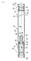
- Fig.1 is an axial cross section of an inflator.
- An inflator 10 comprises a tubular inflator housing 20 made of highly pressure resistant metal such as steel, an ignition means chamber 30 connected to one end and a gas generator 40 connected to the other end.
- the inflator housing 20, the ignition means chamber 30 and the gas generator 40 are formed separately, but these members can be formed as a single member (for example, the inflator housing forms the whole outer shell) and each portion can be separated by a partition wall and a rupturable plate.
- the inner space 22 of the inflator housing 20 is kept airtight state, and argon, helium, nitrogen and so on is charged under high pressure (about 70, 000 kPa at the maximum pressure) .
- An existing gas cylinder can be used as the inflator housing 20, which can be manufactured by swaging a pipe.
- ends of the inflator housing 20 are connected to the ignition means chamber 30 and the gas generator 40, rupturable plates are arranged to be able to keep airtight state, and then, pressurized gas is charged through gap in a sealing pin 24 inserted in a small hole, and thereafter, the inflator housing 20 is welded at the portion of the sealing pin 24.
- the ignition means chamber 30 its outer shell is formed by the ignition means chamber housing 32.
- plural gas discharge ports 34 for ejecting pressurized gas outside are arranged, and a first igniter 36 provided with an priming is accommodated inside.
- the first igniter 36 is connected to a power source (battery of a car) via a connector and a lead wire.
- the first rupturable plate 38 made of stainless is arranged in the first passage 37 between the inflator housing 20 (inner space 22) and the ignition means chamber 30 in the first passage 37 between the inflator housing 20 (inner space 22) and the ignition means chamber 30.
- the inside of the ignition means chamber 30 is under normal pressure since the first passage 37 is closed with the first rupturable plate 38.
- the circumferential edge portion of the first rupturable plate 38 is fixed by welding to a first circular portion 33 made of a radial projection of the inner surface in the ignition means chamber housing 32.
- an outer shell is formed by the gas generator housing 42.
- one end opening portion is connected to the inflator housing 20
- the second igniter 46 is embedded from the other end opening portion, and the second igniter 46 is fixed by crimping circumferential edge 42a of the other end opening portion.
- the remaining space in the gas generator housing 42 except the second igniter 46 forms a combustion chamber 44 in which a gas generating agent 45 for generating combustion gas is loaded.
- a gas generating agent 45 generation time of gas can be made longer by reducing a total surface area (for example, by using one having the same shape as that shown in F ig.1 but a larger size, a total surface area can be reduced even when the same quantity is loaded) or by selecting composition having a low burning rate.
- the second rupturable plate 48 made of stainless is arranged in the second passage 47 between the inflator housing 20 (inner space 22) and the gas generator 40.
- the inside of the gas generator 40 is under normal pressure since the second passage 47 is closed with the second rupturable plate 48.
- the circumferential edge portion of the second rupturable plate 48 is fixed by welding to a second circular portion 43 made of a radial projection of the inner surface in the gas generator housing 42.
- a cap 50 is installed inside the inflator housing 22 such that it completely covers the second rupturable plate 48 and the second passage 47.
- the cap 50 has a flange portion 51 in an opening portion, its bottom surface 52 is closed, and on circumferential surface, it has plural vents 53 having such a size that can allow gas to flow therethrough and catch broken pieces of the rupturable plate.
- the cap 50 is fixed to the gas generator housing 42 at the flange portion 51 by crimping a circular protruding portion 49 arranged on a portion of the gas generator housing 42 which faces the inflator housing 20.
- the inflator housing 20 and the ignition means chamber housing 32, and the inflator housing 20 and the gas generator housing 42 are connected by welding.
- an inflation time of a curtain air bag can be short. Accordingly, only the first igniter 36 is activated and the curtain air bag is inflated and developed only by pressurized gas. However, if a degree of the impact which a vehicle has received is serious, the first igniter 36 and the second igniter 46 activate simultaneously to develop and inflate a curtain air bag by both of pressurized gas and combustion gas. And, if the impact which a vehicle has received is moderate, the first igniter 36 is activated, and then, the second igniter 46 is activated a little later. The following is the description concerning a case in which the first igniter 36 and the second igniter 46 are activated with time lag.
- the first rupturable plate 38 When a vehicle receives an impact from a lateral direction, the first rupturable plate 38 is broken by activation of the first igniter 36, and pressurized gas in the inner space 22 flows through the first passage 37 into the ignition means chamber 30, is ejected from a gas discharge port 34 to inflate and develop a curtain air bag. In this way, an air bag can be instantly inflated and developed in a narrow space between a vehicle occupant and a side surface portion of the vehicle.
- an inflation direction of the curtain air bag can be controlled easily in one direction.
- temperature of pressurized gas rapidly goes down when it is released from high pressure state, an air bag is inflated at high speed, but inflation is maintained for a short time.
- a curtain air bag system which has to develop and inflate an air bag instantly in a narrow space between the vehicle occupant and a side surface portion of the vehicle, that the first igniter 36 only is activated first and pressurized gas can be released instantly. And, it can be applied to a combination of a curtain air bag and a side air bag.
- a gas generating agent 45 in a combustion chamber 44 is burnt to generate combustion gas, and the second rupturable plate 48 is broken by increase in internal pressure.
- the combustion gas passes through a vent 53 of the cap 50, flows into the inner space 22, further goes through the first passage 37 and the ignition means chamber 30, and is discharged from a gas discharge port 34 to maintain inflation and development time of the curtain air bag for about a several seconds.
- a total surface area or composition (burning rate) of the gas generating agent 45 inflation and development time of the curtain air bag can be made still longer.
Landscapes
- Physics & Mathematics (AREA)
- Fluid Mechanics (AREA)
- Engineering & Computer Science (AREA)
- Mechanical Engineering (AREA)
- Air Bags (AREA)
- Feeding, Discharge, Calcimining, Fusing, And Gas-Generation Devices (AREA)
Abstract
An inflator suitable for a curtain air bag is provided.
The inflator has two igniters 36 and 46 and gas discharge ports 34 formed on one end side. A first rupturable plate 38 is broken by activation of the first igniter 36 and pressurized gas is discharged from gas discharge ports 34, and a second rupturable plate 48 is broken by activation of a second igniter 46 and combustion gas is discharged from gas discharge ports 34. Accordingly, the air bag can be inflated instantly and inflation can be maintained.
Description
- The present invention relates to an inflator suitable as an inflator for a curtain air bag installed in an automobile in particular.
- Various kinds of inflators such as an inflator for an air bag of a driver side, an inflator for an air bag of a front passenger side, an inflator for a side air bag, an inflator for a curtain air bag, an inflator for an knee-bolster, an inflator for an inflatable seat belt, an inflator for a tubular system and an inflator for a pretensioner are known as an inflator for inflation type security systems of a motor vehicle, which can protect a vehicle occupant most suitably in accordance with a seat location in a vehicle such as a driver side, a front passenger side and so on.
- Among these inflators, an inflator for a curtain air bag is to instantly inflate and develop a curtain-like air bag having thickness of a few centimeters over a window of a vehicle when a vehicle receives the impact from a lateral direction.
- An inflator for a curtain air bag is demanded to maintain an inflated state for about a few seconds on the assumption that a vehicle rolls in a lateral direction, in addition to inflating a curtain-like air bag instantly. Further, since installation location thereof is limited as compared to an inflator for an air bag of a driver side or a front passenger side, there is a strong request for downsizing the inflator.
- Patent Document 1: WO-A No. 97/08020
- Patent Document 2: WO-A No. 97/32753
- Patent Document 3: US-B No. 5,794,973,
- Patent Document 4: US-B No. 6,039,348
- An object of the present invention is to provide an inflator especially suitable as an inflator for a curtain air bag, in which a direction of inflation and development is controlled easily and that inflation can be maintained for a long time.
- The present invention provides, as a means to solve the problem, an inflator housing comprising a cylindrical inflator housing, an ignition means chamber connected to one end of the cylindrical inflator housing and a gas generator connected to the other end of the cylindrical inflator housing,
wherein the ignition means chamber has an igniter and a gas discharge port, and a first rupturable plate closes between the inside of the inflator housing and the ignition means chamber,
the gas generator has an igniter and a gas generating agent, and a second rupturable plate closes between the inside of the inflator housing and the gas generator, and
pressurized gas is charged under high pressure inside the inflator housing. - In the inflator of the present invention, since gas discharge ports are arranged only on one end portion side, it is suitable for a case of inflating an air bag only in one direction.
- And in this invention, since pressurized gas and combustion gas from a gas generating agent are utilized as an inflation medium for an air bag, in a crash of a vehicle, an air bag can be inflated and developed instantly by the pressurized gas and also, inflation and development time of the air bag can be maintained for about a few (six to seven) seconds by the combustion gas generated by the gas generator.
- In this invention, a cap can be installed inside the inflator housing such that it covers the second rupturable plate from the inner side of the inflator housing, and the cap has a vent having such a size that can allow gas to flow therethorugh and catch broken pieces of the rupturable plate.
- The inflator of the present invention can be applied to well known inflators for air bags, for example, an inflator for an air bag of a driver side, an inflator for an air bag of a front passenger side, an inflator for a side air bag, an inflator for a curtain air bag, and in particular, it is suitable as an inflator for a curtain air bag.
- In the inflator of the present invention, since gas discharge ports are arranged only on one end, it is suitable for a case of inflating and developing an air bag only in one direction. Further in this invention, since pressurized gas and combustion gas from a gas generating agent are utilized as an inflation medium for an air bag, an air bag can be inflated and developed instantly, and also, inflation and development time of the air bag can be maintained for about a few (six to seven) seconds by the combustion gas generated by the gas generating agent. Accordingly, it is suitable as an inflator for a curtain air bag in particular.
- Fig.1 is an axial cross section of an inflator of the present invention.
-
- 10
- inflator
- 20
- inflator housing
- 30
- ignition means chamber
- 36
- first igniter
- 38
- first rupturable plate
- 40
- gas generator
- 45
- gas generating agent
- 46
- second igniter
- 50
- cap
- An embodiment of an inflator of the present invention will be explained according to Fig.1. Fig.1 is an axial cross section of an inflator.
- An
inflator 10 comprises atubular inflator housing 20 made of highly pressure resistant metal such as steel, an ignition meanschamber 30 connected to one end and agas generator 40 connected to the other end. - In Fig. 1, the inflator housing 20, the ignition means
chamber 30 and thegas generator 40 are formed separately, but these members can be formed as a single member (for example, the inflator housing forms the whole outer shell) and each portion can be separated by a partition wall and a rupturable plate. - The
inner space 22 of theinflator housing 20 is kept airtight state, and argon, helium, nitrogen and so on is charged under high pressure (about 70, 000 kPa at the maximum pressure) . - An existing gas cylinder can be used as the
inflator housing 20, which can be manufactured by swaging a pipe. In theinflator 10 of Fig. 1, ends of theinflator housing 20 are connected to the ignition meanschamber 30 and thegas generator 40, rupturable plates are arranged to be able to keep airtight state, and then, pressurized gas is charged through gap in a sealingpin 24 inserted in a small hole, and thereafter, theinflator housing 20 is welded at the portion of the sealingpin 24. - As to the ignition means
chamber 30, its outer shell is formed by the ignition meanschamber housing 32. In the ignition meanschamber housing 32, pluralgas discharge ports 34 for ejecting pressurized gas outside are arranged, and afirst igniter 36 provided with an priming is accommodated inside. Thefirst igniter 36 is connected to a power source (battery of a car) via a connector and a lead wire. - In the
first passage 37 between the inflator housing 20 (inner space 22) and the ignition meanschamber 30, the firstrupturable plate 38 made of stainless is arranged. The inside of the ignition meanschamber 30 is under normal pressure since thefirst passage 37 is closed with the firstrupturable plate 38. The circumferential edge portion of the firstrupturable plate 38 is fixed by welding to a firstcircular portion 33 made of a radial projection of the inner surface in the ignition meanschamber housing 32. - As to the
gas generator 40, an outer shell is formed by thegas generator housing 42. In thegas generator housing 42, one end opening portion is connected to theinflator housing 20, thesecond igniter 46 is embedded from the other end opening portion, and thesecond igniter 46 is fixed by crimpingcircumferential edge 42a of the other end opening portion. - The remaining space in the
gas generator housing 42 except thesecond igniter 46 forms a combustion chamber 44 in which agas generating agent 45 for generating combustion gas is loaded. As to thegas generating agent 45, generation time of gas can be made longer by reducing a total surface area (for example, by using one having the same shape as that shown in Fig.1 but a larger size, a total surface area can be reduced even when the same quantity is loaded) or by selecting composition having a low burning rate. - In the
second passage 47 between the inflator housing 20 (inner space 22) and thegas generator 40, the secondrupturable plate 48 made of stainless is arranged. The inside of thegas generator 40 is under normal pressure since thesecond passage 47 is closed with the secondrupturable plate 48. The circumferential edge portion of the secondrupturable plate 48 is fixed by welding to a secondcircular portion 43 made of a radial projection of the inner surface in thegas generator housing 42. - A
cap 50 is installed inside theinflator housing 22 such that it completely covers the secondrupturable plate 48 and thesecond passage 47. - The
cap 50 has aflange portion 51 in an opening portion, itsbottom surface 52 is closed, and on circumferential surface, it hasplural vents 53 having such a size that can allow gas to flow therethrough and catch broken pieces of the rupturable plate. - The
cap 50 is fixed to thegas generator housing 42 at theflange portion 51 by crimping a circular protrudingportion 49 arranged on a portion of thegas generator housing 42 which faces theinflator housing 20. - The
inflator housing 20 and the ignition meanschamber housing 32, and theinflator housing 20 and thegas generator housing 42 are connected by welding. - Next, operation of the inflator 10 shown in Fig. 1 applied to a curtain air bag is explained.
- By the way, if a degree of the impact which a vehicle has received is small, an inflation time of a curtain air bag can be short. Accordingly, only the
first igniter 36 is activated and the curtain air bag is inflated and developed only by pressurized gas. However, if a degree of the impact which a vehicle has received is serious, thefirst igniter 36 and thesecond igniter 46 activate simultaneously to develop and inflate a curtain air bag by both of pressurized gas and combustion gas. And, if the impact which a vehicle has received is moderate, thefirst igniter 36 is activated, and then, thesecond igniter 46 is activated a little later. The following is the description concerning a case in which thefirst igniter 36 and thesecond igniter 46 are activated with time lag. - When a vehicle receives an impact from a lateral direction, the first
rupturable plate 38 is broken by activation of thefirst igniter 36, and pressurized gas in theinner space 22 flows through thefirst passage 37 into the ignition meanschamber 30, is ejected from agas discharge port 34 to inflate and develop a curtain air bag. In this way, an air bag can be instantly inflated and developed in a narrow space between a vehicle occupant and a side surface portion of the vehicle. - At this time, since the
gas discharge ports 34 are arranged only at one end portion, an inflation direction of the curtain air bag can be controlled easily in one direction. In this case, since temperature of pressurized gas rapidly goes down when it is released from high pressure state, an air bag is inflated at high speed, but inflation is maintained for a short time. However, it is suitable for a curtain air bag system, which has to develop and inflate an air bag instantly in a narrow space between the vehicle occupant and a side surface portion of the vehicle, that thefirst igniter 36 only is activated first and pressurized gas can be released instantly. And, it can be applied to a combination of a curtain air bag and a side air bag. - Subsequently, by activation of the
second igniter 46, agas generating agent 45 in a combustion chamber 44 is burnt to generate combustion gas, and the secondrupturable plate 48 is broken by increase in internal pressure. And the combustion gas passes through avent 53 of thecap 50, flows into theinner space 22, further goes through thefirst passage 37 and the ignition meanschamber 30, and is discharged from agas discharge port 34 to maintain inflation and development time of the curtain air bag for about a several seconds. At this time, by adjusting a total surface area or composition (burning rate) of thegas generating agent 45, inflation and development time of the curtain air bag can be made still longer. - Incidentally, even when pieces are generated by rupture of the second
rupturable plate 48, the pieces are caught by avent 53 in thecap 50, and therefore, pieces, which moves with outflow of combustion gas, never closes thegas discharge port 34 nor are ejected into the air bag.
Claims (3)
- An inflator housing comprising a cylindrical inflator housing, an ignition means chamber connected to one end of the cylindrical inflator housing and a gas generator connected to the other end of the cylindrical inflator housing,
wherein the ignition means chamber has an igniter and a gas discharge port, and a first rupturable plate closes between the inside of the inflator housing and the ignition means chamber,
the gas generator has an igniter and a gas generating agent, and a second rupturable plate closes between the inside of the inflator housing and the gas generator, and
pressurized gas is charged under high pressure inside the inflator housing. - The inflator according to claim 1, wherein a cap is installed inside the inflator housing such that it covers the second rupturable plate from the inner side of the inflator housing, and the cap has a vent having such a size that can allow gas to flow therethrough and catch broken pieces of the rupturable plate.
- The inflator according to claim 1 or 2, which is for a curtain air bag.
Applications Claiming Priority (2)
| Application Number | Priority Date | Filing Date | Title |
|---|---|---|---|
| JP2003150256A JP2004352008A (en) | 2003-05-28 | 2003-05-28 | Inflator |
| PCT/JP2004/006942 WO2004106123A1 (en) | 2003-05-28 | 2004-05-21 | Inflator |
Publications (2)
| Publication Number | Publication Date |
|---|---|
| EP1634779A1 true EP1634779A1 (en) | 2006-03-15 |
| EP1634779A4 EP1634779A4 (en) | 2006-12-13 |
Family
ID=33487171
Family Applications (1)
| Application Number | Title | Priority Date | Filing Date |
|---|---|---|---|
| EP04734351A Withdrawn EP1634779A4 (en) | 2003-05-28 | 2004-05-21 | INFLATOR |
Country Status (4)
| Country | Link |
|---|---|
| EP (1) | EP1634779A4 (en) |
| JP (1) | JP2004352008A (en) |
| CN (1) | CN100375691C (en) |
| WO (1) | WO2004106123A1 (en) |
Families Citing this family (9)
| Publication number | Priority date | Publication date | Assignee | Title |
|---|---|---|---|---|
| JP2008081098A (en) * | 2006-08-30 | 2008-04-10 | Toyoda Gosei Co Ltd | Airbag device |
| JP4821654B2 (en) * | 2007-02-28 | 2011-11-24 | 豊田合成株式会社 | Inflator |
| DE102009008673B3 (en) | 2009-02-12 | 2010-08-19 | Schott Ag | Punched feedthrough element with soldered contact pin |
| DE102011080342A1 (en) * | 2011-08-03 | 2013-02-07 | Robert Bosch Gmbh | Cold gas generator for providing cold gas for activation of an impact bag and method for providing cold gas for an impact bag activation |
| KR20180011073A (en) * | 2015-05-22 | 2018-01-31 | 주식회사 다이셀 | gas producer |
| CN108325120B (en) * | 2018-03-01 | 2021-08-24 | 合肥龙精灵信息技术有限公司 | Insert installation type quick inflation device |
| JP7211866B2 (en) * | 2019-03-25 | 2023-01-24 | 株式会社ダイセル | metal assembly and inflator |
| CN112172731A (en) * | 2019-07-05 | 2021-01-05 | 标致雪铁龙汽车股份有限公司 | Vehicle initiative gas curtain equipment and vehicle |
| CN112172733A (en) * | 2019-07-05 | 2021-01-05 | 标致雪铁龙汽车股份有限公司 | Gas generator for vehicle airbag, method of operation thereof, and vehicle |
Family Cites Families (10)
| Publication number | Priority date | Publication date | Assignee | Title |
|---|---|---|---|---|
| TW299291B (en) * | 1994-10-25 | 1997-03-01 | Oea Inc | |
| JPH10297416A (en) * | 1997-04-25 | 1998-11-10 | Matsushita Electric Ind Co Ltd | Gas generator for airbag device and airbag inflation method |
| JPH11129858A (en) * | 1997-10-31 | 1999-05-18 | Fuji Heavy Ind Ltd | Inflator of air bag for vehicle |
| US6116641A (en) * | 1998-01-22 | 2000-09-12 | Atlantic Research Corporation | Dual level gas generator |
| JP2000264178A (en) | 1999-03-12 | 2000-09-26 | Aichi Mach Ind Co Ltd | Parking device for vehicle |
| DE19930239A1 (en) * | 1999-06-25 | 2001-01-04 | Petri Ag | Air bag unit has controller for maintaining internal pressure of air bag in pressure range specified for protection of occupant for defined period after full inflation |
| DE19933551A1 (en) * | 1999-07-16 | 2001-01-18 | Autoliv Dev | Inflatable hybrid device for motor safety devices has pyrotechnic charges outside gas chamber for generating gas, each with mass of at least 5 per cent of mass of compressed gas |
| DE10040822A1 (en) * | 1999-08-23 | 2001-04-19 | Trw Inc | Inflatable protection device for vehicle passengers has first and second chambers with current flow from second chamber controlled by mechanism to hold restraint inflated for four or more seconds |
| US6431595B1 (en) * | 1999-12-22 | 2002-08-13 | Trw Inc. | Long duration air bag inflator |
| US6601872B2 (en) * | 2001-08-16 | 2003-08-05 | Atlantic Research Corporation | Compact multi-level inflator |
-
2003
- 2003-05-28 JP JP2003150256A patent/JP2004352008A/en active Pending
-
2004
- 2004-05-21 EP EP04734351A patent/EP1634779A4/en not_active Withdrawn
- 2004-05-21 CN CNB2004800146436A patent/CN100375691C/en not_active Expired - Fee Related
- 2004-05-21 WO PCT/JP2004/006942 patent/WO2004106123A1/en not_active Ceased
Also Published As
| Publication number | Publication date |
|---|---|
| JP2004352008A (en) | 2004-12-16 |
| CN100375691C (en) | 2008-03-19 |
| EP1634779A4 (en) | 2006-12-13 |
| CN1795117A (en) | 2006-06-28 |
| WO2004106123A1 (en) | 2004-12-09 |
Similar Documents
| Publication | Publication Date | Title |
|---|---|---|
| JP4814082B2 (en) | Gunpowder inflator for automotive airbag systems | |
| US7328914B2 (en) | Inflator | |
| US9205802B1 (en) | Hybrid inflator device for a passive restraint air bag system | |
| KR20000071004A (en) | Improved airbag inflator for vehicle occupant restraint apparatus | |
| EP1613508B1 (en) | Belt and side impact inflator | |
| US7293797B2 (en) | Inflator | |
| JP2000280855A (en) | Expansion type constraining system having selectable ventilation | |
| EP1634779A1 (en) | Inflator | |
| EP1003653B1 (en) | Miniature inflator | |
| JP2003025951A (en) | Inflator | |
| EP1547878B1 (en) | Airbag inflator | |
| EP3707032B1 (en) | Pressure wave generating inflator device with slidable gas generator | |
| US7641224B2 (en) | Vehicle occupant restraint system including an airbag | |
| JP2008542097A (en) | Vehicle occupant protection system | |
| US7032925B2 (en) | Rupturable plate for inflator | |
| US20050029788A1 (en) | Inflator | |
| US7246818B2 (en) | Inflator | |
| US7168734B2 (en) | Inflator for air bag | |
| EP1454804B1 (en) | Burst plate for inflator | |
| EP1550587A1 (en) | Inflator | |
| EP1627782A1 (en) | Inflator | |
| US7204513B2 (en) | Gas generator for an occupant protection system of a vehicle | |
| KR100205584B1 (en) | Inflator for Air Bag | |
| WO2013123371A1 (en) | Shockwave generating mechanism for automotive inflator deployment | |
| JP2006160049A (en) | Small inflator for airbag |
Legal Events
| Date | Code | Title | Description |
|---|---|---|---|
| PUAI | Public reference made under article 153(3) epc to a published international application that has entered the european phase |
Free format text: ORIGINAL CODE: 0009012 |
|
| 17P | Request for examination filed |
Effective date: 20051125 |
|
| AK | Designated contracting states |
Kind code of ref document: A1 Designated state(s): DE FR |
|
| DAX | Request for extension of the european patent (deleted) | ||
| RBV | Designated contracting states (corrected) |
Designated state(s): DE FR |
|
| A4 | Supplementary search report drawn up and despatched |
Effective date: 20061113 |
|
| 17Q | First examination report despatched |
Effective date: 20070507 |
|
| STAA | Information on the status of an ep patent application or granted ep patent |
Free format text: STATUS: THE APPLICATION IS DEEMED TO BE WITHDRAWN |
|
| 18D | Application deemed to be withdrawn |
Effective date: 20070918 |