EP1634714A1 - Method for printing a substrate with an ink jet printer and an inkjet printer for applying the said method - Google Patents
Method for printing a substrate with an ink jet printer and an inkjet printer for applying the said method Download PDFInfo
- Publication number
- EP1634714A1 EP1634714A1 EP05107889A EP05107889A EP1634714A1 EP 1634714 A1 EP1634714 A1 EP 1634714A1 EP 05107889 A EP05107889 A EP 05107889A EP 05107889 A EP05107889 A EP 05107889A EP 1634714 A1 EP1634714 A1 EP 1634714A1
- Authority
- EP
- European Patent Office
- Prior art keywords
- substrate
- transport
- roll
- guide element
- printing
- Prior art date
- Legal status (The legal status is an assumption and is not a legal conclusion. Google has not performed a legal analysis and makes no representation as to the accuracy of the status listed.)
- Granted
Links
- 239000000758 substrate Substances 0.000 title claims abstract description 183
- 238000000034 method Methods 0.000 title claims abstract description 18
- 238000011144 upstream manufacturing Methods 0.000 claims description 6
- 230000032258 transport Effects 0.000 description 114
- 230000001133 acceleration Effects 0.000 description 4
- 238000010586 diagram Methods 0.000 description 4
- 238000006073 displacement reaction Methods 0.000 description 2
- 230000000694 effects Effects 0.000 description 2
- 239000000725 suspension Substances 0.000 description 2
- 230000002411 adverse Effects 0.000 description 1
- 239000003086 colorant Substances 0.000 description 1
- 238000010276 construction Methods 0.000 description 1
- 230000001419 dependent effect Effects 0.000 description 1
- 230000008092 positive effect Effects 0.000 description 1
- 230000000717 retained effect Effects 0.000 description 1
- 230000035939 shock Effects 0.000 description 1
- 239000006163 transport media Substances 0.000 description 1
Images


Classifications
-
- B—PERFORMING OPERATIONS; TRANSPORTING
- B41—PRINTING; LINING MACHINES; TYPEWRITERS; STAMPS
- B41J—TYPEWRITERS; SELECTIVE PRINTING MECHANISMS, i.e. MECHANISMS PRINTING OTHERWISE THAN FROM A FORME; CORRECTION OF TYPOGRAPHICAL ERRORS
- B41J15/00—Devices or arrangements of selective printing mechanisms, e.g. ink-jet printers or thermal printers, specially adapted for supporting or handling copy material in continuous form, e.g. webs
- B41J15/005—Forming loops or sags in webs, e.g. for slackening a web or for compensating variations of the amount of conveyed web material (by arranging a "dancing roller" in a sag of the web material)
-
- B—PERFORMING OPERATIONS; TRANSPORTING
- B41—PRINTING; LINING MACHINES; TYPEWRITERS; STAMPS
- B41J—TYPEWRITERS; SELECTIVE PRINTING MECHANISMS, i.e. MECHANISMS PRINTING OTHERWISE THAN FROM A FORME; CORRECTION OF TYPOGRAPHICAL ERRORS
- B41J11/00—Devices or arrangements of selective printing mechanisms, e.g. ink-jet printers or thermal printers, for supporting or handling copy material in sheet or web form
- B41J11/0075—Low-paper indication, i.e. indicating the state when copy material has been used up nearly or completely
-
- B—PERFORMING OPERATIONS; TRANSPORTING
- B41—PRINTING; LINING MACHINES; TYPEWRITERS; STAMPS
- B41J—TYPEWRITERS; SELECTIVE PRINTING MECHANISMS, i.e. MECHANISMS PRINTING OTHERWISE THAN FROM A FORME; CORRECTION OF TYPOGRAPHICAL ERRORS
- B41J11/00—Devices or arrangements of selective printing mechanisms, e.g. ink-jet printers or thermal printers, for supporting or handling copy material in sheet or web form
- B41J11/36—Blanking or long feeds; Feeding to a particular line, e.g. by rotation of platen or feed roller
- B41J11/42—Controlling printing material conveyance for accurate alignment of the printing material with the printhead; Print registering
-
- B—PERFORMING OPERATIONS; TRANSPORTING
- B41—PRINTING; LINING MACHINES; TYPEWRITERS; STAMPS
- B41J—TYPEWRITERS; SELECTIVE PRINTING MECHANISMS, i.e. MECHANISMS PRINTING OTHERWISE THAN FROM A FORME; CORRECTION OF TYPOGRAPHICAL ERRORS
- B41J15/00—Devices or arrangements of selective printing mechanisms, e.g. ink-jet printers or thermal printers, specially adapted for supporting or handling copy material in continuous form, e.g. webs
- B41J15/04—Supporting, feeding, or guiding devices; Mountings for web rolls or spindles
-
- B—PERFORMING OPERATIONS; TRANSPORTING
- B41—PRINTING; LINING MACHINES; TYPEWRITERS; STAMPS
- B41J—TYPEWRITERS; SELECTIVE PRINTING MECHANISMS, i.e. MECHANISMS PRINTING OTHERWISE THAN FROM A FORME; CORRECTION OF TYPOGRAPHICAL ERRORS
- B41J15/00—Devices or arrangements of selective printing mechanisms, e.g. ink-jet printers or thermal printers, specially adapted for supporting or handling copy material in continuous form, e.g. webs
- B41J15/18—Multiple web-feeding apparatus
Definitions
- the invention relates to a method of printing a substrate using an inkjet printer, which printer comprises a holder to rotatably receive a roll on which the substrate is wound, a downstream print zone and an inkjet printhead for printing the substrate at the print zone, a transport means for engaging and transporting the substrate to the print zone during which transport the substrate is unwound from the roll, and a guide element which is situated downstream of the roll in front of the transport means to guide the substrate from the roll to the transport means, the method comprising: transporting the substrate over a predetermined distance with control of the transport means, during which transport the guide element is moved from a first position which said element occupies prior to the transport, to a second position such that the distance over which the substrate extends between the roll and the transport means is smaller as a result of the movement and after the substrate has been transported over the predetermined distance, printing a strip of the substrate with control of the inkjet printhead, and after printing of the strip the re-transport of the substrate over a predetermined distance during which the guide element
- the transport means which is frequently a transport nip which engages the substrate at a number of places distributed over the width of the substrate, has a lower mass inertia than the roll on which the substrate is wound, at least when there is a specific minimum amount of substrate present on the roll.
- the transport of the substrate and its simultaneous unwinding from the roll can in that case take place at adequate speed if the transport means is, for example, driven by a very powerful motor, both the transport means and the roll being accelerated.
- the result of such a powerful motor is that considerable forces are exerted on the substrate, with the risk that the substrate will tear.
- a powerful motor of this kind has the disadvantage that it is less suitable for very accurate control.
- a disadvantage of this method is that for accurate transport of the substrate by the transport means there is required not only an accurate drive but also a very accurate transport means and guide element.
- the mechanical tolerances such as roundness, straightness, mutual parallelism, etc, are subject to 'stringent requirements in order that transport may take place with the required accuracy.
- Even with very close tolerances there are still a relatively large number of irregularly recurring juxtaposition faults between the sub-images. These juxtaposition faults are indications of random faults in the substrate transport.
- the object of the invention is to obviate the above disadvantages.
- a method according to the preamble has been invented which is characterised in that the guide element is brought into the first position prior to the re-transport of the substrate.
- the guide element is first brought into the same initial position. This is possible if the substrate, during each transport increment, is transported by the transport means the same distance as said substrate is unwound from the roll. Since the mass inertia of the roll differs from that of the transport means, the transport of the substrate by the transport means and the unwinding of the substrate from the roll are out of phase, but this difference can be compensated by the movement of the guide element.
- the guide element Since the guide element is in each case brought to the initial position, the method of transport including all faults therein which occur due to out of true, crookedness, non-parallelism, friction, slip, compliance, etc, is practically the same each time and there is therefore a pattern of regular deviations in the transport. Since they are known in advance, it is possible easily to compensate for these regularly recurring faults. Thus it is possible to use transport means and guide elements with less accurate mechanical tolerances.
- a part of the substrate is unwound from the roll first prior to control of the transport means for the purpose of such transport.
- the method starts first with unwinding part of the substrate from the roll.
- This loop can be restricted to a minimum, for example, by moving the guide element.
- the transport medium itself is not actuated until some time later. Directly prior to this, care is taken to ensure that the guide element is in its fixed initial position. Since the roll has already been unwound one increment, there will be no shortage of "free” substrate even in the event of considerable acceleration of the transport means.
- this tension can be reduced by moving the guide element in the direction of the second position.
- the guide element is returned to the first position, and if necessary a corresponding amount of substrate is unwound from the roll for the purpose by driving the drive motor for the roll.
- the maximum speed at which the substrate is unwound from the roll during transport of the substrate is less than the maximum speed of transport imparted by the transport means.
- This embodiment has the advantage that the roll, which may have a relatively high mass inertia, does not acquire any very high speed of revolution. That could in fact cause problems during the stoppage of the roll. Rapid braking of an inert roll may cause shocks and hence have a negative effect on the accuracy of the substrate transport.
- the requirements to be met by the drive motor for the roll are reduced because as a result of the lower maximum speed it is possible to apply reduced accelerations.
- the invention also relates to an inkjet printer for printing a substrate, provided with a holder to rotatably receive a roll on which the substrate is wound, a downstream print zone and an inkjet printhead for printing the substrate at the print zone, a transport means for engaging and transporting the substrate to the print zone, and a guide element which is situated downstream of the roll in front of the transport means to guide the substrate from the roll to the transport means, wherein the guide element is disposed movably in the printer in such manner that it can be moved between a first position in which the distance over which the substrate extends between the roll and the transport means has a first value, and a second position in which said distance has a second value less than the first, characterised in that the printer is provided with a control unit which ensures that the guide element occupies the first position directly prior to the transport of the substrate over a predetermined distance having as its objective to make a strip of the substrate available for printing.
- this printer is provided with a spring element which provides resistance to displacement of the guide element.
- the spring is disposed parallel to the guide element. It has been found in this way that it is very easy to provide adequate resistance to movement of the guide element, said resistance being sufficiently low not to have an adverse effect on the substrate transport.
- the spring consists of a number of weak springs coupled in series.
- the printer upstream of the guide element the printer has a second transport means for transporting the substrate.
- the advantage of this embodiment is that there is a further decoupling of forces between the drive for the first transport means and the drive for the roll.
- the substrate can be kept taut between the first and second transport means despite the fact that a section of substrate has already been unwound from the roll prior to transport by the first transport means. This gives more possibilities of accurate transport of the substrate.
- the guide element is a roller which comprises a shaft on which a number of substantially congruent (identical in shape) wheels are disposed.
- the roller is provided with a curved guide plate to guide the substrate to the roller. This has been found advantageous during introduction of the web over the transport means, and can have a positive effect on further preventing unwanted mechanical wear of the substrate during its transport.
- Fig. 1 is a diagram of a printer according to the present invention.
- This printer is provided with the supply unit 10, which serves for the storage and delivery of the substrate for printing.
- this printer comprises a transport unit 30 which transports the substrate from the supply unit 10 to the print engine 40.
- Unit 30 also provides accurate positioning of the substrate in the print zone formed between the print surface 42 and the inkjet printhead 41.
- print engine 40 is a conventional engine which comprises printhead 41, which printhead is constructed from a number of separate sub-heads, each of one of the colours: black, cyan, magenta and yellow.
- Printhead 41 has only a limited printing range so that it is necessary to print the image on the substrate in different sub-images.
- the substrate is transported an increment in each case so that a new part of the substrate can be printed in the print zone.
- the substrate 12 comes from a roll 11 from the supply unit 10.
- a web of the substrate is wound on this roll, the web having a length of 200 metres.
- the supply unit is provided with a holder (not shown) to receive the roll rotatably.
- This holder consists of two parts mounted in side plates of the printer, which parts are brought into co-operative connection with the ends of the roll.
- the supply unit is provided with a second holder to receive roll 21.
- Another substrate 22 is wound on this roll and can also be delivered by the supply unit for printing.
- roll 11 is operatively connected to transport means 15, which means in this case comprises a pair of rolls between which a transport nip is formed. More particularly, means 15 relates to a set of two shafts each extending in a direction substantially parallel to roll 11, on which shafts a number of roll pairs are mounted each forming a transport nip for the substrate. In an alternative embodiment, only one roll pair is mounted on the shafts, substantially coinciding with the middle of the web 12.
- Upstream of means 15 is a sensor 17, by means of which it is possible to determine whether there is still substrate on the roll situated in the associated holder. As soon as the roll is used up, the end of the web will pass the sensor, and this is detected by the sensor.
- the supply holder is provided with transport means 25. Upstream of this means the supply holder is provided with sensor 27, which has the same action as sensor 17.
- the supply holder is provided with guide elements 16 and 26 to guide the substrates 12 and 22 respectively to the transport unit 30. Downstream of these guide elements, there is a transit path 13. This transit path is used both for the transport of substrate 12 and the transport of substrate 22.
- a substrate leaving the supply unit 10, in this example substrate 12, is engaged by transport means 31 of the transport unit 30.
- This transport means transports the substrate via guide element 33 on to the second transport means 32 of the transport unit 30.
- the transport means 32 engages the substrate, transports it to print engine 40 and ensures good positioning of the substrate in the print zone between the print surface 42 and the printhead 41.
- the transport means 31 and 32 extend substantially parallel to the rolls 11 and 21, and have a length such that the substrate can be engaged over substantially its entire width.
- the guide elements 16 and 26 are in this example rollers extending parallel to the transport means 15 and 31; 25 and 31 respectively. They are substantially stationary rollers, i.e. they cannot rotate about their axial axis. For the substrate 12 illustrated, this means that during transport the substrate slides over element 16 and is at the same time fed in the direction of transport means 31.
- this configuration it has been found that movement of the substrate at the guide element in a direction parallel to the direction in which the element extends is possible. In other words, the substrate can in this way make a lateral movement with respect to the direction in which said substrate is transported.
- the reason that a lateral movement of this kind is possible in this configuration is associated with the fact that the substrate makes a sliding movement with respect to the guide element. As a result, the required frictional force to set the substrate in motion initially with respect to the guide element is already overcome and practically no force is needed to move the substrate laterally over the guide element.
- the guide elements are so disposed in the supply unit that they can each rotate, at least through a limited angle, about an axis substantially perpendicular to the direction in which said guide elements extend (i.e. the axial direction of the guide elements).
- the rotational axis 18 of element 16 is shown, and also rotational axis 28 of element 26. These rotational axes are perpendicular to the axes of the guide elements and intersect the centre of said elements.
- This axis 35 intersects the centre of the substrate web at a distance of about 1 metre from the guide element itself.
- the substrate makes a substantially lateral movement.
- the possibility of rotation of element 33 over the axes of 34 and 35 ensures flexible and accurate transport of the substrate from transport means 31 to transport means 32, even though the two means do not extend 100% parallel to one another.
- Guide element 33 is movable from a first position in which said element is situated in Fig. 1, to a second position in which the centre of this element coincides with the location 37. In the first position, the distance over which substrate 12 extends between transport means 31 and transport means 32 is at a maximum. In the second position this distance is at a minimum. Use is made of this fact during the transport of the substrate to print engine 40. Since the substrate must in each case be moved over a relatively short distance, typically 5 to 10 cm, it is advantageous for this to occur relatively quickly. The mass inertia of roll 11, certainly when it is provided with the maximum quantity of substrate, is relatively high however. For this reason, if the configuration of transport means and guide elements as illustrated were maintained, movement would take relatively considerable time.
- transport means 31 is accelerated much more slowly than transport means 32.
- the guide element 33 is moved in the direction of location 37.
- the residue at transport means 31 is compensated by allowing the said transport means to continue rotating for some time.
- the element 33 is moved back to the first position.
- guide element 33 is in the same initial starting position. It has been found that in this way very accurate transport of the substrate is possible. As a result, the various sub-images can match up more satisfactorily and the number of print artefacts can be reduced.
- the provision of accurate transport and particularly accurate positioning of the substrate in the print zone by control of means 32 is related to the fact that the substrate is engaged by both means 31 and means 32.
- the position of the substrate is more satisfactorily defined as a result.
- very accurate transport and positioning of the substrate is obtained, the tension in the substrate not increasing to an extent such that under normal circumstances mechanical damage of the substrate would occur.
- An important additional advantage of this arrangement is that printing can still be continued on the substrate as long as the end of the web has not passed transport means 31. The instant at which this happens can easily be determined if the end of the web is detected by means of the sensor 17 or 27 corresponding to this web.
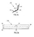
- Fig. 2 shows a guide element 116 which can be used in a preferred embodiment as a guide for the substrate in the supply unit 10 (instead of the guide element 16 and/or 26).
- Fig. 2A is a side elevation of this element.
- This element comprises a bent plate comprising a part 200 situated upstream of the bend 202, and a part 201 which is situated downstream of the bend 202.
- Part 200 is connected by spot welds 206 to the rigid frame part 205.
- the frame part 205 is a U-profile extending over the length of element 116 and connected to the frame of the printer.
- Part 201 of the plate is much less restricted in its freedom of movement than part 202.
- Yoke 210 fixed on the U-profile 205 on its own provides a point of support for part 201, and in this connection see the front elevation of element 116 as shown in Fig. 2B. It will be clear from this front elevation that part 201 is substantially free. Since the plate is relatively thin, part 201 is torsionally weak and can at least partially rotate about the axis passing through the centre of the yoke 210 and perpendicular to the longitudinal axis of element 116. In one embodiment, part 201 is provided with slots so that this part has less resistance to torsion.
- Fig. 3 is a diagram of one embodiment of guide element 33.
- element 33 comprises a shaft 300 on which a series of transport wheels 301 are disposed. The substrate is guided over these wheels. Since the shaft is suspended to be freely rotatable, it can co-rotate with the substrate without any mutual difference in speeds. As a result, the frictional force accompanying the transport of the substrate at the roller is practically only dependent on the friction in the mounting of this roller.
- Element 33 is provided with a guide plate 302 bent in the form of a V to assist in guiding the substrate. It should also be clear that the V-shape of the element 302 substantially coincides with the V-shape of the substrate as shown in Fig. 1.
- Shaft 300 is resiliently suspended by leaf springs 305 and 306 which are fixed to be freely rotatable on fixed frame parts 307 and 308 respectively. These leaf springs each form the same angle with the shaft in such manner that the centre lines of the leaf springs have a point of intersection 310 upstream of the roller. Rotational axis 35 intersects this point of intersection.
- Fig. 3B shows the suspension of the shaft in greater detail.
- the leaf spring 305 is fixed on the end of shaft 300.
- Leaf spring 305 is in turn fixed on shaft 311 which is suspended to be freely rotatable in U-shaped frame part 307. By means of this suspension it is possible for roller 33 to rotate about the axes 34 and 35. Although the rotational possibility is finite, it appears to be sufficient to make possible accurate and reliable transport of the substrate between the nips 31 and 32.
- Fig. 3C diagrammatically shows the spring mechanism with which roller 33 is pushed in the indicated direction A.
- This direction A coincides with the direction extending from the above-mentioned second position that the element 33 can occupy (see Fig. 1, location 37) to the first position that the element occupies in Fig. 1.
- the shaft 300 is provided with side panels 315 and 316 which at their end remote from the shaft are provided with elements 317 and 318 respectively.
- the set of weak springs 322, 323 and 324 is fixed on these elements, this set being guided over freely rotatable wheels 320 and 321.
- the springs are to some extent stretched so that they tend to move the ends of the set of springs to the centre thereof, as indicated in Fig. 3C.
- the elements 317 and 318, and hence the shaft 300 are pushed in the indicated direction A.
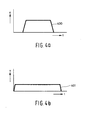
- Fig. 4 diagrammatically shows the speeds at which the substrate is transported through the transport nips 32 (Fig. 4A) and 31 (Fig. 4B) during the passage of part of said substrate so that a new strip thereof can be printed using inkjet printhead 41.
- Curve 400 in Fig. 4A shows what speed of passage is imposed on the substrate at the nip 32. A high speed of transit is generated relatively quickly and this is retained for some time and then drops to zero rapidly. Despite the high mass inertia of the roll on which the substrate is wound, this high acceleration can be obtained by moving roller 33 as indicated under Fig. 1.
- Curve 401 in Fig. 4B shows the speed of transit imposed on the substrate at nip 31 for the transport of the same length of the substrate. It will be seen that this nip is driven before nip 32 so that the substrate is already partly unwound from roll 11 before nip 32 is driven. It may happen that movement of the roller 33 will enable the web to be tensioned between the means 31 and 32.
- the acceleration which is imparted by nip 31 is smaller than that of nip 32, and the maximum speed of transit that this nip provides is lower. However, the substrate is passed through for a longer time so that ultimately the same length of the substrate passes the nip 31.
Landscapes
- Ink Jet (AREA)
- Handling Of Continuous Sheets Of Paper (AREA)
- Controlling Rewinding, Feeding, Winding, Or Abnormalities Of Webs (AREA)
Abstract
Description
- The invention relates to a method of printing a substrate using an inkjet printer, which printer comprises a holder to rotatably receive a roll on which the substrate is wound, a downstream print zone and an inkjet printhead for printing the substrate at the print zone, a transport means for engaging and transporting the substrate to the print zone during which transport the substrate is unwound from the roll, and a guide element which is situated downstream of the roll in front of the transport means to guide the substrate from the roll to the transport means, the method comprising: transporting the substrate over a predetermined distance with control of the transport means, during which transport the guide element is moved from a first position which said element occupies prior to the transport, to a second position such that the distance over which the substrate extends between the roll and the transport means is smaller as a result of the movement and after the substrate has been transported over the predetermined distance, printing a strip of the substrate with control of the inkjet printhead, and after printing of the strip the re-transport of the substrate over a predetermined distance during which the guide element is moved, which transport is followed by printing a following strip of the substrate.
- This method is used inter alia to prevent damage to the substrate during its transport. The transport means, which is frequently a transport nip which engages the substrate at a number of places distributed over the width of the substrate, has a lower mass inertia than the roll on which the substrate is wound, at least when there is a specific minimum amount of substrate present on the roll. The transport of the substrate and its simultaneous unwinding from the roll can in that case take place at adequate speed if the transport means is, for example, driven by a very powerful motor, both the transport means and the roll being accelerated. The result of such a powerful motor is that considerable forces are exerted on the substrate, with the risk that the substrate will tear. In addition, a powerful motor of this kind has the disadvantage that it is less suitable for very accurate control. In inkjet printers in particular, accurate control of the transport means is very important, because printing often takes place by printing the substrate in a number of swaths, and in each swath part of the substrate is printed, often a strip of the same width as the inkjet printhead. All the sub-images together form the image for printing. For accurate juxtaposition of the sub-images, accurate transport of the substrate is desirable.
- It has been chosen to provide the transport means with a low-power driving motor and to dispose a movable guide element between the roll and the transport means. By moving this element, it is possible to reduce the distance over which the substrate extends between the roll and the transport means. This prevents any sudden increase in the substrate tension. The motor that drives the transport means consequently does not have to move the entire roll each time. It is thus possible to use a relatively low power drive for the transport means, it being a relatively simple matter to make such drive accurate. In this method, the roll can be driven separately with a powerful but less accurate motor.
- A disadvantage of this method is that for accurate transport of the substrate by the transport means there is required not only an accurate drive but also a very accurate transport means and guide element. The mechanical tolerances such as roundness, straightness, mutual parallelism, etc, are subject to 'stringent requirements in order that transport may take place with the required accuracy. In addition, even with very close tolerances, there are still a relatively large number of irregularly recurring juxtaposition faults between the sub-images. These juxtaposition faults are indications of random faults in the substrate transport.
- The object of the invention is to obviate the above disadvantages. To this end, a method according to the preamble has been invented which is characterised in that the guide element is brought into the first position prior to the re-transport of the substrate.
- Thus whenever the substrate is moved an increment for printing of a following strip, the guide element is first brought into the same initial position. This is possible if the substrate, during each transport increment, is transported by the transport means the same distance as said substrate is unwound from the roll. Since the mass inertia of the roll differs from that of the transport means, the transport of the substrate by the transport means and the unwinding of the substrate from the roll are out of phase, but this difference can be compensated by the movement of the guide element.
- It has been found that the application of this method results in far fewer irregularly recurring juxtaposition faults between the sub-images. Regularly recurring juxtaposition faults still occur, but this problem can be obviated easily by calibration. As is sufficiently known from the prior art, regularly recurring faults can easily be taken into account, for example during control of the inkjet printhead or heads, so that these faults can be completely eliminated.
- Since the guide element is in each case brought to the initial position, the method of transport including all faults therein which occur due to out of true, crookedness, non-parallelism, friction, slip, compliance, etc, is practically the same each time and there is therefore a pattern of regular deviations in the transport. Since they are known in advance, it is possible easily to compensate for these regularly recurring faults. Thus it is possible to use transport means and guide elements with less accurate mechanical tolerances.
- In one embodiment, in order to transport the substrate to the print zone, a part of the substrate is unwound from the roll first prior to control of the transport means for the purpose of such transport. In this embodiment, therefore, the method starts first with unwinding part of the substrate from the roll. This gives a kind of loop of "free" substrate. This loop can be restricted to a minimum, for example, by moving the guide element. The transport medium itself is not actuated until some time later. Directly prior to this, care is taken to ensure that the guide element is in its fixed initial position. Since the roll has already been unwound one increment, there will be no shortage of "free" substrate even in the event of considerable acceleration of the transport means. As soon as there is a risk of excessive tension in the substrate as a result of further transport thereof, this tension can be reduced by moving the guide element in the direction of the second position. After the transport of the substrate is complete, the guide element is returned to the first position, and if necessary a corresponding amount of substrate is unwound from the roll for the purpose by driving the drive motor for the roll.
- In another embodiment, the maximum speed at which the substrate is unwound from the roll during transport of the substrate is less than the maximum speed of transport imparted by the transport means. This embodiment has the advantage that the roll, which may have a relatively high mass inertia, does not acquire any very high speed of revolution. That could in fact cause problems during the stoppage of the roll. Rapid braking of an inert roll may cause shocks and hence have a negative effect on the accuracy of the substrate transport. In addition, the requirements to be met by the drive motor for the roll are reduced because as a result of the lower maximum speed it is possible to apply reduced accelerations.
- The invention also relates to an inkjet printer for printing a substrate, provided with a holder to rotatably receive a roll on which the substrate is wound, a downstream print zone and an inkjet printhead for printing the substrate at the print zone, a transport means for engaging and transporting the substrate to the print zone, and a guide element which is situated downstream of the roll in front of the transport means to guide the substrate from the roll to the transport means, wherein the guide element is disposed movably in the printer in such manner that it can be moved between a first position in which the distance over which the substrate extends between the roll and the transport means has a first value, and a second position in which said distance has a second value less than the first, characterised in that the printer is provided with a control unit which ensures that the guide element occupies the first position directly prior to the transport of the substrate over a predetermined distance having as its objective to make a strip of the substrate available for printing.
- In one embodiment this printer is provided with a spring element which provides resistance to displacement of the guide element. By the use of a spring element it is possible to obtain a relatively low resistance to movement of the guide element. This can further minimise any build-up of tension in the substrate.
- In another embodiment, the spring is disposed parallel to the guide element. It has been found in this way that it is very easy to provide adequate resistance to movement of the guide element, said resistance being sufficiently low not to have an adverse effect on the substrate transport. In yet another embodiment the spring consists of a number of weak springs coupled in series.
- In one embodiment, upstream of the guide element the printer has a second transport means for transporting the substrate. The advantage of this embodiment is that there is a further decoupling of forces between the drive for the first transport means and the drive for the roll. Thus the substrate can be kept taut between the first and second transport means despite the fact that a section of substrate has already been unwound from the roll prior to transport by the first transport means. This gives more possibilities of accurate transport of the substrate.
- In one embodiment, the guide element is a roller which comprises a shaft on which a number of substantially congruent (identical in shape) wheels are disposed. In yet another embodiment, the roller is provided with a curved guide plate to guide the substrate to the roller. This has been found advantageous during introduction of the web over the transport means, and can have a positive effect on further preventing unwanted mechanical wear of the substrate during its transport.
- The invention will now be explained in detail with reference to the following examples.
- Fig. 1 is a diagram of a printer according to a specific embodiment of the present invention.
- Fig. 2 shows a guide element that can be used as a guide for the substrate.
- Fig. 3 shows another embodiment of a guide element.
- Fig. 4 is a diagram showing the speeds at which the substrate is transported through the transport nips 32 (Fig. 4A) and 31 (Fig. 4B).
- Fig. 1 is a diagram of a printer according to the present invention. This printer is provided with the
supply unit 10, which serves for the storage and delivery of the substrate for printing. In addition, this printer comprises atransport unit 30 which transports the substrate from thesupply unit 10 to theprint engine 40.Unit 30 also provides accurate positioning of the substrate in the print zone formed between theprint surface 42 and the inkjet printhead 41. In this embodiment,print engine 40 is a conventional engine which comprises printhead 41, which printhead is constructed from a number of separate sub-heads, each of one of the colours: black, cyan, magenta and yellow. Printhead 41 has only a limited printing range so that it is necessary to print the image on the substrate in different sub-images. To this end, the substrate is transported an increment in each case so that a new part of the substrate can be printed in the print zone. In the example illustrated, thesubstrate 12 comes from aroll 11 from thesupply unit 10. A web of the substrate is wound on this roll, the web having a length of 200 metres. To accommodate the roll in the printer, the supply unit is provided with a holder (not shown) to receive the roll rotatably. This holder consists of two parts mounted in side plates of the printer, which parts are brought into co-operative connection with the ends of the roll. In this embodiment, the supply unit is provided with a second holder to receiveroll 21. Anothersubstrate 22 is wound on this roll and can also be delivered by the supply unit for printing. For the transport of the substrate, roll 11 is operatively connected to transport means 15, which means in this case comprises a pair of rolls between which a transport nip is formed. More particularly, means 15 relates to a set of two shafts each extending in a direction substantially parallel to roll 11, on which shafts a number of roll pairs are mounted each forming a transport nip for the substrate. In an alternative embodiment, only one roll pair is mounted on the shafts, substantially coinciding with the middle of theweb 12. - Upstream of
means 15 is asensor 17, by means of which it is possible to determine whether there is still substrate on the roll situated in the associated holder. As soon as the roll is used up, the end of the web will pass the sensor, and this is detected by the sensor. For the transport of a substrate originating fromroll 21, the supply holder is provided with transport means 25. Upstream of this means the supply holder is provided withsensor 27, which has the same action assensor 17. The supply holder is provided withguide elements substrates transport unit 30. Downstream of these guide elements, there is atransit path 13. This transit path is used both for the transport ofsubstrate 12 and the transport ofsubstrate 22. - A substrate leaving the
supply unit 10, in thisexample substrate 12, is engaged by transport means 31 of thetransport unit 30. This transport means transports the substrate viaguide element 33 on to the second transport means 32 of thetransport unit 30. The transport means 32 engages the substrate, transports it to printengine 40 and ensures good positioning of the substrate in the print zone between theprint surface 42 and the printhead 41. The transport means 31 and 32 extend substantially parallel to therolls - The
guide elements substrate 12 illustrated, this means that during transport the substrate slides overelement 16 and is at the same time fed in the direction of transport means 31. When this configuration is used it has been found that movement of the substrate at the guide element in a direction parallel to the direction in which the element extends is possible. In other words, the substrate can in this way make a lateral movement with respect to the direction in which said substrate is transported. The reason that a lateral movement of this kind is possible in this configuration is associated with the fact that the substrate makes a sliding movement with respect to the guide element. As a result, the required frictional force to set the substrate in motion initially with respect to the guide element is already overcome and practically no force is needed to move the substrate laterally over the guide element. - The guide elements are so disposed in the supply unit that they can each rotate, at least through a limited angle, about an axis substantially perpendicular to the direction in which said guide elements extend (i.e. the axial direction of the guide elements). In the Figure, the
rotational axis 18 ofelement 16 is shown, and also rotational axis 28 ofelement 26. These rotational axes are perpendicular to the axes of the guide elements and intersect the centre of said elements. As a result of this rotation combined with the possibility of moving the substrate laterally, the substrate has been found to have very good guidance from thesupply unit 10 to nip 31 of thetransport unit 30. As a result, despite the fact that the transport means 15 and 31; 25 and 31 respectively are not perfectly parallel, it is nevertheless possible to transport the substrate without any damage thereto. -
Guide element 33 oftransport unit 30, which element extends substantially parallel to the transport means 31 and 32, is also so disposed that it can rotate about an axis perpendicular to the axial direction of said element. This axis is shown byreference 34 and intersects the centre ofguide element 33. Sinceelement 33 in this embodiment is a co-rotating roller, the substrate is substantially stationary with respect to the surface of said guide element. As a result, a lateral movement of the said substrate at said element is made difficult. In order that such a movement can be made possible,element 33 is so suspended that it can rotate aboutaxis 35, whichaxis 35 extends parallel to thebisector 36 of the angle 2α over which the substrate is fed from means 31 tomeans 32. Thisaxis 35 intersects the centre of the substrate web at a distance of about 1 metre from the guide element itself. On rotation ofelement 33 about this axis, the substrate makes a substantially lateral movement. The possibility of rotation ofelement 33 over the axes of 34 and 35 ensures flexible and accurate transport of the substrate from transport means 31 to transport means 32, even though the two means do not extend 100% parallel to one another. -
Guide element 33 is movable from a first position in which said element is situated in Fig. 1, to a second position in which the centre of this element coincides with thelocation 37. In the first position, the distance over whichsubstrate 12 extends between transport means 31 and transport means 32 is at a maximum. In the second position this distance is at a minimum. Use is made of this fact during the transport of the substrate to printengine 40. Since the substrate must in each case be moved over a relatively short distance, typically 5 to 10 cm, it is advantageous for this to occur relatively quickly. The mass inertia ofroll 11, certainly when it is provided with the maximum quantity of substrate, is relatively high however. For this reason, if the configuration of transport means and guide elements as illustrated were maintained, movement would take relatively considerable time. To counteract this problem, transport means 31 is accelerated much more slowly than transport means 32. In order nevertheless to ensure adequate supply of substrate to transport means 32, theguide element 33 is moved in the direction oflocation 37. As a result, there is no lack of substrate at transport means 32 during its passage to printengine 40. If the passage by means 32 is stopped, the residue at transport means 31 is compensated by allowing the said transport means to continue rotating for some time. In these conditions, theelement 33 is moved back to the first position. In this way, prior to a following transport of a part of the substrate requiring printing withprint engine 40,guide element 33 is in the same initial starting position. It has been found that in this way very accurate transport of the substrate is possible. As a result, the various sub-images can match up more satisfactorily and the number of print artefacts can be reduced. - The provision of accurate transport and particularly accurate positioning of the substrate in the print zone by control of
means 32, is related to the fact that the substrate is engaged by bothmeans 31 and means 32. The position of the substrate is more satisfactorily defined as a result. Together with the rotational possibilities ofguide element 33, in this way very accurate transport and positioning of the substrate is obtained, the tension in the substrate not increasing to an extent such that under normal circumstances mechanical damage of the substrate would occur. An important additional advantage of this arrangement is that printing can still be continued on the substrate as long as the end of the web has not passed transport means 31. The instant at which this happens can easily be determined if the end of the web is detected by means of thesensor print engine 40 before said end of the web passes themeans 31. In this way it is possible to determine whether the image printed at that instant can still be completely imaged on the substrate without the end of the web passing the first transport means. If so, that image will be completed. If not, then it is possible to choose to stop printing. However, when the end of the web passes means 31 the transport and the positioning of the substrate may be accompanied by more errors, and this may result in print artefacts. Too many artefacts can result in the image having to be reprinted. In order to save ink and substrate it is therefore better to stop printing. - If it is still possible to print the current image on the substrate (without the end of the web passing the means 31), it is then possible to determine whether the next image for printing can still be printed on the substrate (without the end of the web passing the means 31). If so, that image will be printed. If not, then it is better to print this following image on a new substrate, for example originating from
roll 21. - Fig. 2 shows a
guide element 116 which can be used in a preferred embodiment as a guide for the substrate in the supply unit 10 (instead of theguide element 16 and/or 26). Fig. 2A is a side elevation of this element. This element comprises a bent plate comprising apart 200 situated upstream of thebend 202, and apart 201 which is situated downstream of thebend 202.Part 200 is connected byspot welds 206 to therigid frame part 205. Theframe part 205 is a U-profile extending over the length ofelement 116 and connected to the frame of the printer. Part 201 of the plate is much less restricted in its freedom of movement thanpart 202.Yoke 210 fixed on the U-profile 205 on its own provides a point of support forpart 201, and in this connection see the front elevation ofelement 116 as shown in Fig. 2B. It will be clear from this front elevation thatpart 201 is substantially free. Since the plate is relatively thin,part 201 is torsionally weak and can at least partially rotate about the axis passing through the centre of theyoke 210 and perpendicular to the longitudinal axis ofelement 116. In one embodiment,part 201 is provided with slots so that this part has less resistance to torsion. - If
element 116 is placed in the supply unit to replaceelement 116, the free end ofplate part 200 points towards the transport nip 15 andpart 201 is practically parallel to transitpath 13 of the supply unit.Element 116 is also stationary in the supply unit. As a result of the tension in thesubstrate part 201 can be pulled againstyoke 210. As a result, the ends particularly ofpart 201 can rotate about the axis passing through the centre of the yoke, perpendicularly to the direction in whichelement 116 extends. The advantages of this rotational possibility are described under Fig. 1. - Fig. 3 is a diagram of one embodiment of
guide element 33. In thisembodiment element 33 comprises ashaft 300 on which a series oftransport wheels 301 are disposed. The substrate is guided over these wheels. Since the shaft is suspended to be freely rotatable, it can co-rotate with the substrate without any mutual difference in speeds. As a result, the frictional force accompanying the transport of the substrate at the roller is practically only dependent on the friction in the mounting of this roller. -
Element 33 is provided with aguide plate 302 bent in the form of a V to assist in guiding the substrate. It should also be clear that the V-shape of theelement 302 substantially coincides with the V-shape of the substrate as shown in Fig. 1.Shaft 300 is resiliently suspended byleaf springs frame parts intersection 310 upstream of the roller.Rotational axis 35 intersects this point of intersection. Fig. 3B shows the suspension of the shaft in greater detail. Theleaf spring 305 is fixed on the end ofshaft 300.Leaf spring 305 is in turn fixed onshaft 311 which is suspended to be freely rotatable inU-shaped frame part 307. By means of this suspension it is possible forroller 33 to rotate about theaxes nips - Fig. 3C diagrammatically shows the spring mechanism with which
roller 33 is pushed in the indicated direction A. This direction A coincides with the direction extending from the above-mentioned second position that theelement 33 can occupy (see Fig. 1, location 37) to the first position that the element occupies in Fig. 1. To this end, theshaft 300 is provided withside panels elements weak springs rotatable wheels elements shaft 300, are pushed in the indicated direction A. - Since the construction chosen results in a resistance to the displacement of the roller, a stiffness in respect of movement of translation is introduced for the roller in principle. During movement of the roller to the second position, the resistance to this movement becomes increasingly greater. The advantage of this resistance is that the movement of the roller takes place more accurately and more satisfactorily reproducibly. By placing a number of long weak springs in series, this resistance remains sufficiently small but very effective.
- Fig. 4 diagrammatically shows the speeds at which the substrate is transported through the transport nips 32 (Fig. 4A) and 31 (Fig. 4B) during the passage of part of said substrate so that a new strip thereof can be printed using inkjet printhead 41.
-
Curve 400 in Fig. 4A shows what speed of passage is imposed on the substrate at thenip 32. A high speed of transit is generated relatively quickly and this is retained for some time and then drops to zero rapidly. Despite the high mass inertia of the roll on which the substrate is wound, this high acceleration can be obtained by movingroller 33 as indicated under Fig. 1. -
Curve 401 in Fig. 4B shows the speed of transit imposed on the substrate at nip 31 for the transport of the same length of the substrate. It will be seen that this nip is driven before nip 32 so that the substrate is already partly unwound fromroll 11 before nip 32 is driven. It may happen that movement of theroller 33 will enable the web to be tensioned between themeans nip 31 is smaller than that of nip 32, and the maximum speed of transit that this nip provides is lower. However, the substrate is passed through for a longer time so that ultimately the same length of the substrate passes thenip 31.
Claims (10)
- A method of printing a substrate using an inkjet printer, which printer comprises a holder to rotatably receive a roll on which the substrate is wound, a downstream print zone and an inkjet printhead for printing the substrate at the print zone, a transport means for engaging and transporting the substrate to the print zone during which transport the substrate is unwound from the roll, and a guide element which is situated downstream of the roll in front of the transport means to guide the substrate from the roll to the transport means, the method comprising:- transporting the substrate over a predetermined distance with control of the transport means, during which transport the guide element is moved from a first position which said element occupies prior to the transport, to a second position such that the distance over which the substrate extends between the roll and the transport means is smaller as a result of the movement and- after the substrate has been transported over the predetermined distance, printing a strip of the substrate with control of the inkjet printhead, and- after printing of the strip, the re-transport of the substrate over a predetermined distance during which the guide element is moved, which transport is followed by printing a following strip of the substrate,
characterised in that the guide element is brought into the first position prior to the re-transport of the substrate. - A method according to claim 1, characterised in that prior to each movement of the substrate in the transport direction, if said movement is directed to making a new strip of the substrate available for printing, the guide element is brought into the first position.
- A method according to any one of the preceding claims, characterised in that in order to transport the substrate to the print zone, a part of the substrate is unwound from the roll first prior to control of the transport means for the purpose of such transport.
- A method according to claim 3, characterised in that during the transport of the substrate the maximum speed at which the substrate is unwound from the roll is less than the maximum speed of transport imparted by the transport means.
- An inkjet printer for printing a substrate, provided with a holder to rotatably receive a roll on which the substrate is wound, a downstream print zone and an inkjet printhead for printing the substrate at the print zone, a transport means for engaging and transporting the substrate to the print zone, and a guide element which is situated downstream of the roll in front of the transport means to guide the substrate from the roll to the transport means, wherein the guide element is disposed movably in the printer in such manner that it can be moved between a first position in which the distance over which the substrate extends between the roll and the transport means has a first value, and a second position in which said distance has a second value less than the first, characterised in that the printer is provided with a control unit which ensures that the guide element occupies the first position directly prior to the transport of the substrate over a predetermined distance having as its objective to make a strip of the substrate available for printing.
- An inkjet printer according to claim 5, characterised in that it is provided with a spring element which provides resistance to movement of the guide element.
- An inkjet printer according to claim 6, characterised in that the spring is disposed parallel to the guide element.
- An inkjet printer according to any one of claims 5 to 7, characterised in that upstream of the guide element it has a second transport means for transporting the substrate.
- An inkjet printer according to any one of claims 5 to 8, characterised in that the guide element is a roller which has a shaft on which a number of substantially congruent wheels are disposed.
- An inkjet printer according to claim 9, characterised in that the roller is provided with a curved guide plate to guide the substrate to and from the roller.
Applications Claiming Priority (1)
| Application Number | Priority Date | Filing Date | Title |
|---|---|---|---|
| NL1027002A NL1027002C2 (en) | 2004-09-09 | 2004-09-09 | Method for printing a substrate with an inkjet printer, and an inkjet printer suitable for applying this method. |
Publications (2)
| Publication Number | Publication Date |
|---|---|
| EP1634714A1 true EP1634714A1 (en) | 2006-03-15 |
| EP1634714B1 EP1634714B1 (en) | 2012-02-15 |
Family
ID=34974428
Family Applications (1)
| Application Number | Title | Priority Date | Filing Date |
|---|---|---|---|
| EP05107889A Expired - Lifetime EP1634714B1 (en) | 2004-09-09 | 2005-08-29 | Method for printing a substrate with an ink jet printer and an inkjet printer for applying the said method |
Country Status (6)
| Country | Link |
|---|---|
| US (1) | US7794078B2 (en) |
| EP (1) | EP1634714B1 (en) |
| JP (1) | JP4970757B2 (en) |
| CN (1) | CN1746035B (en) |
| AT (1) | ATE545512T1 (en) |
| NL (1) | NL1027002C2 (en) |
Families Citing this family (8)
| Publication number | Priority date | Publication date | Assignee | Title |
|---|---|---|---|---|
| CN101941335B (en) * | 2009-07-06 | 2012-06-06 | 山东新北洋信息技术股份有限公司 | Slice type medium processing device with two feeding channels |
| CN102873992A (en) * | 2012-10-12 | 2013-01-16 | 易程(苏州)电子科技股份有限公司 | Double-invoice-volume invoice printer |
| US8746690B1 (en) * | 2013-01-16 | 2014-06-10 | Eastman Kodak Company | Duplexing unit with freely rotatable contact surface |
| US9381758B2 (en) * | 2014-06-04 | 2016-07-05 | Roland Dg Corporation | Carrier device and inkjet printer having the same, and carrying method |
| US9925763B2 (en) * | 2016-01-21 | 2018-03-27 | Seiko Epson Corporation | Print system |
| JP7251221B2 (en) * | 2019-03-08 | 2023-04-04 | セイコーエプソン株式会社 | Printing device and printing method |
| CN112390050A (en) * | 2019-08-12 | 2021-02-23 | 山东新北洋信息技术股份有限公司 | Printer and paper conveying method |
| CN111332007A (en) * | 2020-03-04 | 2020-06-26 | 宁同洋 | Thermal transfer printer |
Citations (3)
| Publication number | Priority date | Publication date | Assignee | Title |
|---|---|---|---|---|
| US4165029A (en) * | 1977-09-28 | 1979-08-21 | Silonics, Inc. | Paper advance mechanism for an ink jet printer |
| EP0666180A2 (en) * | 1994-02-08 | 1995-08-09 | Canon Kabushiki Kaisha | Image forming apparatus |
| EP1219454A2 (en) * | 2000-12-20 | 2002-07-03 | Olivetti Tecnost S.p.A. | Device for the intermittent feeding of a strip of paper from a roll |
Family Cites Families (16)
| Publication number | Priority date | Publication date | Assignee | Title |
|---|---|---|---|---|
| JPS60157255U (en) * | 1984-03-30 | 1985-10-19 | 株式会社 サト− | Appropriate feeding device for band-shaped members |
| JPS622558U (en) * | 1985-06-20 | 1987-01-09 | ||
| JPH0261860U (en) * | 1988-10-28 | 1990-05-09 | ||
| JP2635179B2 (en) * | 1989-09-08 | 1997-07-30 | 株式会社日立製作所 | Thermal transfer recording apparatus and thermal transfer recording method |
| EP0419185B1 (en) * | 1989-09-18 | 1999-03-31 | Canon Kabushiki Kaisha | Conveying rotational member for an ink recording apparatus |
| GB9026002D0 (en) * | 1990-11-29 | 1991-01-16 | Molins Plc | Web tension control |
| JP3245302B2 (en) * | 1993-07-22 | 2002-01-15 | キヤノン株式会社 | Sheet member conveying device and information processing device using the same |
| US5717836A (en) * | 1995-03-09 | 1998-02-10 | Matsushita Electric Industrial Co., Ltd. | Printing apparatus having a retractable curl removal member and reversible roller |
| JP2859224B2 (en) * | 1996-10-31 | 1999-02-17 | 日本電気株式会社 | Recording device |
| JPH1179508A (en) * | 1997-09-08 | 1999-03-23 | Hitachi Ltd | Image recording device |
| JP3955673B2 (en) * | 1998-02-27 | 2007-08-08 | Mutohホールディングス株式会社 | Printer |
| AU2001236761A1 (en) * | 2000-02-03 | 2001-08-14 | David A. Estabrooks | On demand media web electrophotographic printing apparatus |
| US6634745B2 (en) * | 2000-12-28 | 2003-10-21 | Canon Kabushiki Kaisha | Image forming apparatus |
| JP3778264B2 (en) * | 2001-01-31 | 2006-05-24 | セイコーエプソン株式会社 | Roll paper slack forming apparatus and recording apparatus provided with the roll paper slack forming apparatus |
| DE10247455B4 (en) * | 2002-10-11 | 2006-04-27 | OCé PRINTING SYSTEMS GMBH | Apparatus and method for controlling the position of the side edge of a continuous web |
| JP3897007B2 (en) * | 2003-07-31 | 2007-03-22 | ブラザー工業株式会社 | Inkjet printer |
-
2004
- 2004-09-09 NL NL1027002A patent/NL1027002C2/en not_active IP Right Cessation
-
2005
- 2005-08-29 AT AT05107889T patent/ATE545512T1/en active
- 2005-08-29 EP EP05107889A patent/EP1634714B1/en not_active Expired - Lifetime
- 2005-08-30 JP JP2005249292A patent/JP4970757B2/en not_active Expired - Fee Related
- 2005-09-08 US US11/220,640 patent/US7794078B2/en not_active Expired - Fee Related
- 2005-09-09 CN CN2005100998860A patent/CN1746035B/en not_active Expired - Fee Related
Patent Citations (3)
| Publication number | Priority date | Publication date | Assignee | Title |
|---|---|---|---|---|
| US4165029A (en) * | 1977-09-28 | 1979-08-21 | Silonics, Inc. | Paper advance mechanism for an ink jet printer |
| EP0666180A2 (en) * | 1994-02-08 | 1995-08-09 | Canon Kabushiki Kaisha | Image forming apparatus |
| EP1219454A2 (en) * | 2000-12-20 | 2002-07-03 | Olivetti Tecnost S.p.A. | Device for the intermittent feeding of a strip of paper from a roll |
Also Published As
| Publication number | Publication date |
|---|---|
| EP1634714B1 (en) | 2012-02-15 |
| JP4970757B2 (en) | 2012-07-11 |
| NL1027002C2 (en) | 2006-03-13 |
| US7794078B2 (en) | 2010-09-14 |
| CN1746035A (en) | 2006-03-15 |
| ATE545512T1 (en) | 2012-03-15 |
| JP2006076297A (en) | 2006-03-23 |
| CN1746035B (en) | 2011-07-06 |
| US20060050129A1 (en) | 2006-03-09 |
Similar Documents
| Publication | Publication Date | Title |
|---|---|---|
| JP5406808B2 (en) | Continuous web conveying system used in continuous web image forming apparatus | |
| US8646995B2 (en) | Image recording apparatus | |
| US5087141A (en) | Combination pinch roller and carriage guide for printer | |
| US7794078B2 (en) | Method of printing a substrate with an inkjet printer, and an inkjet printer suitable for performing this method | |
| US7331575B2 (en) | Printer and method for feeding sheets in a printer | |
| EP1634715A1 (en) | Printer | |
| US20070104526A1 (en) | Ribbon tensioning mechanisms | |
| EP1634716B1 (en) | Inkjet printer | |
| JP5233030B2 (en) | Web processing device | |
| US20060181018A1 (en) | Sheet handling device | |
| JP4339630B2 (en) | Roll paper supply mechanism for recording device | |
| US20060104699A1 (en) | Printer and supply unit for use in the printer | |
| EP1657192B1 (en) | Printer with substrate provided from a roll supported on a core | |
| JP2009113265A (en) | Recording device | |
| KR200143410Y1 (en) | Feeder in Ink-Jet Printers | |
| JP2006240803A (en) | Belt drive | |
| JPH0922211A (en) | Fixing device |
Legal Events
| Date | Code | Title | Description |
|---|---|---|---|
| PUAI | Public reference made under article 153(3) epc to a published international application that has entered the european phase |
Free format text: ORIGINAL CODE: 0009012 |
|
| AK | Designated contracting states |
Kind code of ref document: A1 Designated state(s): AT BE BG CH CY CZ DE DK EE ES FI FR GB GR HU IE IS IT LI LT LU LV MC NL PL PT RO SE SI SK TR |
|
| AX | Request for extension of the european patent |
Extension state: AL BA HR MK YU |
|
| 17P | Request for examination filed |
Effective date: 20060915 |
|
| 17Q | First examination report despatched |
Effective date: 20061017 |
|
| AKX | Designation fees paid |
Designated state(s): AT BE BG CH CY CZ DE DK EE ES FI FR GB GR HU IE IS IT LI LT LU LV MC NL PL PT RO SE SI SK TR |
|
| GRAP | Despatch of communication of intention to grant a patent |
Free format text: ORIGINAL CODE: EPIDOSNIGR1 |
|
| GRAS | Grant fee paid |
Free format text: ORIGINAL CODE: EPIDOSNIGR3 |
|
| GRAA | (expected) grant |
Free format text: ORIGINAL CODE: 0009210 |
|
| AK | Designated contracting states |
Kind code of ref document: B1 Designated state(s): AT BE BG CH CY CZ DE DK EE ES FI FR GB GR HU IE IS IT LI LT LU LV MC NL PL PT RO SE SI SK TR |
|
| REG | Reference to a national code |
Ref country code: CH Ref legal event code: EP Ref country code: GB Ref legal event code: FG4D |
|
| REG | Reference to a national code |
Ref country code: IE Ref legal event code: FG4D |
|
| REG | Reference to a national code |
Ref country code: AT Ref legal event code: REF Ref document number: 545512 Country of ref document: AT Kind code of ref document: T Effective date: 20120315 |
|
| REG | Reference to a national code |
Ref country code: DE Ref legal event code: R096 Ref document number: 602005032667 Country of ref document: DE Effective date: 20120412 |
|
| REG | Reference to a national code |
Ref country code: NL Ref legal event code: T3 |
|
| LTIE | Lt: invalidation of european patent or patent extension |
Effective date: 20120215 |
|
| PG25 | Lapsed in a contracting state [announced via postgrant information from national office to epo] |
Ref country code: LT Free format text: LAPSE BECAUSE OF FAILURE TO SUBMIT A TRANSLATION OF THE DESCRIPTION OR TO PAY THE FEE WITHIN THE PRESCRIBED TIME-LIMIT Effective date: 20120215 Ref country code: IS Free format text: LAPSE BECAUSE OF FAILURE TO SUBMIT A TRANSLATION OF THE DESCRIPTION OR TO PAY THE FEE WITHIN THE PRESCRIBED TIME-LIMIT Effective date: 20120615 |
|
| PG25 | Lapsed in a contracting state [announced via postgrant information from national office to epo] |
Ref country code: BE Free format text: LAPSE BECAUSE OF FAILURE TO SUBMIT A TRANSLATION OF THE DESCRIPTION OR TO PAY THE FEE WITHIN THE PRESCRIBED TIME-LIMIT Effective date: 20120215 Ref country code: PT Free format text: LAPSE BECAUSE OF FAILURE TO SUBMIT A TRANSLATION OF THE DESCRIPTION OR TO PAY THE FEE WITHIN THE PRESCRIBED TIME-LIMIT Effective date: 20120615 Ref country code: FI Free format text: LAPSE BECAUSE OF FAILURE TO SUBMIT A TRANSLATION OF THE DESCRIPTION OR TO PAY THE FEE WITHIN THE PRESCRIBED TIME-LIMIT Effective date: 20120215 Ref country code: GR Free format text: LAPSE BECAUSE OF FAILURE TO SUBMIT A TRANSLATION OF THE DESCRIPTION OR TO PAY THE FEE WITHIN THE PRESCRIBED TIME-LIMIT Effective date: 20120516 Ref country code: PL Free format text: LAPSE BECAUSE OF FAILURE TO SUBMIT A TRANSLATION OF THE DESCRIPTION OR TO PAY THE FEE WITHIN THE PRESCRIBED TIME-LIMIT Effective date: 20120215 Ref country code: LV Free format text: LAPSE BECAUSE OF FAILURE TO SUBMIT A TRANSLATION OF THE DESCRIPTION OR TO PAY THE FEE WITHIN THE PRESCRIBED TIME-LIMIT Effective date: 20120215 |
|
| REG | Reference to a national code |
Ref country code: AT Ref legal event code: MK05 Ref document number: 545512 Country of ref document: AT Kind code of ref document: T Effective date: 20120215 |
|
| PG25 | Lapsed in a contracting state [announced via postgrant information from national office to epo] |
Ref country code: CY Free format text: LAPSE BECAUSE OF FAILURE TO SUBMIT A TRANSLATION OF THE DESCRIPTION OR TO PAY THE FEE WITHIN THE PRESCRIBED TIME-LIMIT Effective date: 20120215 |
|
| PG25 | Lapsed in a contracting state [announced via postgrant information from national office to epo] |
Ref country code: RO Free format text: LAPSE BECAUSE OF FAILURE TO SUBMIT A TRANSLATION OF THE DESCRIPTION OR TO PAY THE FEE WITHIN THE PRESCRIBED TIME-LIMIT Effective date: 20120215 Ref country code: SI Free format text: LAPSE BECAUSE OF FAILURE TO SUBMIT A TRANSLATION OF THE DESCRIPTION OR TO PAY THE FEE WITHIN THE PRESCRIBED TIME-LIMIT Effective date: 20120215 Ref country code: CZ Free format text: LAPSE BECAUSE OF FAILURE TO SUBMIT A TRANSLATION OF THE DESCRIPTION OR TO PAY THE FEE WITHIN THE PRESCRIBED TIME-LIMIT Effective date: 20120215 Ref country code: SE Free format text: LAPSE BECAUSE OF FAILURE TO SUBMIT A TRANSLATION OF THE DESCRIPTION OR TO PAY THE FEE WITHIN THE PRESCRIBED TIME-LIMIT Effective date: 20120215 Ref country code: EE Free format text: LAPSE BECAUSE OF FAILURE TO SUBMIT A TRANSLATION OF THE DESCRIPTION OR TO PAY THE FEE WITHIN THE PRESCRIBED TIME-LIMIT Effective date: 20120215 Ref country code: DK Free format text: LAPSE BECAUSE OF FAILURE TO SUBMIT A TRANSLATION OF THE DESCRIPTION OR TO PAY THE FEE WITHIN THE PRESCRIBED TIME-LIMIT Effective date: 20120215 |
|
| PG25 | Lapsed in a contracting state [announced via postgrant information from national office to epo] |
Ref country code: IT Free format text: LAPSE BECAUSE OF FAILURE TO SUBMIT A TRANSLATION OF THE DESCRIPTION OR TO PAY THE FEE WITHIN THE PRESCRIBED TIME-LIMIT Effective date: 20120215 Ref country code: SK Free format text: LAPSE BECAUSE OF FAILURE TO SUBMIT A TRANSLATION OF THE DESCRIPTION OR TO PAY THE FEE WITHIN THE PRESCRIBED TIME-LIMIT Effective date: 20120215 |
|
| PLBE | No opposition filed within time limit |
Free format text: ORIGINAL CODE: 0009261 |
|
| STAA | Information on the status of an ep patent application or granted ep patent |
Free format text: STATUS: NO OPPOSITION FILED WITHIN TIME LIMIT |
|
| 26N | No opposition filed |
Effective date: 20121116 |
|
| PG25 | Lapsed in a contracting state [announced via postgrant information from national office to epo] |
Ref country code: AT Free format text: LAPSE BECAUSE OF FAILURE TO SUBMIT A TRANSLATION OF THE DESCRIPTION OR TO PAY THE FEE WITHIN THE PRESCRIBED TIME-LIMIT Effective date: 20120215 |
|
| REG | Reference to a national code |
Ref country code: DE Ref legal event code: R097 Ref document number: 602005032667 Country of ref document: DE Effective date: 20121116 |
|
| REG | Reference to a national code |
Ref country code: CH Ref legal event code: PL |
|
| PG25 | Lapsed in a contracting state [announced via postgrant information from national office to epo] |
Ref country code: MC Free format text: LAPSE BECAUSE OF NON-PAYMENT OF DUE FEES Effective date: 20120831 |
|
| PG25 | Lapsed in a contracting state [announced via postgrant information from national office to epo] |
Ref country code: LI Free format text: LAPSE BECAUSE OF NON-PAYMENT OF DUE FEES Effective date: 20120831 Ref country code: ES Free format text: LAPSE BECAUSE OF FAILURE TO SUBMIT A TRANSLATION OF THE DESCRIPTION OR TO PAY THE FEE WITHIN THE PRESCRIBED TIME-LIMIT Effective date: 20120526 Ref country code: CH Free format text: LAPSE BECAUSE OF NON-PAYMENT OF DUE FEES Effective date: 20120831 |
|
| REG | Reference to a national code |
Ref country code: IE Ref legal event code: MM4A |
|
| PG25 | Lapsed in a contracting state [announced via postgrant information from national office to epo] |
Ref country code: BG Free format text: LAPSE BECAUSE OF FAILURE TO SUBMIT A TRANSLATION OF THE DESCRIPTION OR TO PAY THE FEE WITHIN THE PRESCRIBED TIME-LIMIT Effective date: 20120515 Ref country code: IE Free format text: LAPSE BECAUSE OF NON-PAYMENT OF DUE FEES Effective date: 20120829 |
|
| PG25 | Lapsed in a contracting state [announced via postgrant information from national office to epo] |
Ref country code: TR Free format text: LAPSE BECAUSE OF FAILURE TO SUBMIT A TRANSLATION OF THE DESCRIPTION OR TO PAY THE FEE WITHIN THE PRESCRIBED TIME-LIMIT Effective date: 20120215 |
|
| PG25 | Lapsed in a contracting state [announced via postgrant information from national office to epo] |
Ref country code: LU Free format text: LAPSE BECAUSE OF NON-PAYMENT OF DUE FEES Effective date: 20120829 |
|
| PG25 | Lapsed in a contracting state [announced via postgrant information from national office to epo] |
Ref country code: HU Free format text: LAPSE BECAUSE OF FAILURE TO SUBMIT A TRANSLATION OF THE DESCRIPTION OR TO PAY THE FEE WITHIN THE PRESCRIBED TIME-LIMIT Effective date: 20050829 |
|
| REG | Reference to a national code |
Ref country code: FR Ref legal event code: PLFP Year of fee payment: 11 |
|
| PGFP | Annual fee paid to national office [announced via postgrant information from national office to epo] |
Ref country code: NL Payment date: 20150827 Year of fee payment: 11 |
|
| PGFP | Annual fee paid to national office [announced via postgrant information from national office to epo] |
Ref country code: DE Payment date: 20150821 Year of fee payment: 11 Ref country code: GB Payment date: 20150819 Year of fee payment: 11 |
|
| PGFP | Annual fee paid to national office [announced via postgrant information from national office to epo] |
Ref country code: FR Payment date: 20150820 Year of fee payment: 11 |
|
| REG | Reference to a national code |
Ref country code: DE Ref legal event code: R119 Ref document number: 602005032667 Country of ref document: DE |
|
| REG | Reference to a national code |
Ref country code: NL Ref legal event code: MM Effective date: 20160901 |
|
| GBPC | Gb: european patent ceased through non-payment of renewal fee |
Effective date: 20160829 |
|
| REG | Reference to a national code |
Ref country code: FR Ref legal event code: ST Effective date: 20170428 |
|
| PG25 | Lapsed in a contracting state [announced via postgrant information from national office to epo] |
Ref country code: NL Free format text: LAPSE BECAUSE OF NON-PAYMENT OF DUE FEES Effective date: 20160901 |
|
| PG25 | Lapsed in a contracting state [announced via postgrant information from national office to epo] |
Ref country code: GB Free format text: LAPSE BECAUSE OF NON-PAYMENT OF DUE FEES Effective date: 20160829 Ref country code: FR Free format text: LAPSE BECAUSE OF NON-PAYMENT OF DUE FEES Effective date: 20160831 Ref country code: DE Free format text: LAPSE BECAUSE OF NON-PAYMENT OF DUE FEES Effective date: 20170301 |