EP1634711A2 - Image forming apparatus for correcting magnification of image - Google Patents
Image forming apparatus for correcting magnification of image Download PDFInfo
- Publication number
- EP1634711A2 EP1634711A2 EP05019884A EP05019884A EP1634711A2 EP 1634711 A2 EP1634711 A2 EP 1634711A2 EP 05019884 A EP05019884 A EP 05019884A EP 05019884 A EP05019884 A EP 05019884A EP 1634711 A2 EP1634711 A2 EP 1634711A2
- Authority
- EP
- European Patent Office
- Prior art keywords
- adjustment amount
- image
- magnification
- scanning direction
- horizontal scanning
- Prior art date
- Legal status (The legal status is an assumption and is not a legal conclusion. Google has not performed a legal analysis and makes no representation as to the accuracy of the status listed.)
- Granted
Links
Images



























Classifications
-
- G—PHYSICS
- G02—OPTICS
- G02B—OPTICAL ELEMENTS, SYSTEMS OR APPARATUS
- G02B26/00—Optical devices or arrangements for the control of light using movable or deformable optical elements
- G02B26/08—Optical devices or arrangements for the control of light using movable or deformable optical elements for controlling the direction of light
- G02B26/10—Scanning systems
- G02B26/12—Scanning systems using multifaceted mirrors
- G02B26/127—Adaptive control of the scanning light beam, e.g. using the feedback from one or more detectors
Definitions
- the present invention relates to an image forming apparatus.
- a photoconductor which is an image carrier
- a horizontal scanning direction i.e., main scanning direction
- optical beams laser beams
- the deflector can be, for example, a rotating polygon mirror.
- Optical beams are deflected at an isometric velocity in the horizontal scanning direction by the deflector, and the optical beams are corrected from deflection at the isometric velocity to deflection at a uniform velocity by a f ⁇ lens.
- the f ⁇ lenses can be made from different material including plastic. However, if an f ⁇ lens made of plastic is used, its shape and/or refractive index can change with the surrounding temperature. If the shape or the refractive index changes, a scanning position on the photoconductor deviates, which results in a magnification error in the horizontal scanning direction. The magnification error leads to a degraded image. The refractive index also changes with the wavelength of the laser beam.
- laser beams scanned in the horizontal scanning direction are respectively detected by laser beam detectors provided at two positions in the horizontal scanning direction, the time difference between detections of the laser beams in the two detectors is measured, and the magnification in the horizontal scanning direction is corrected based on this time difference.
- Laser printers are disclosed in Japanese Patent Application Laid-open No. 2003-279873.
- a scanning target surface is scanned in the horizontal scanning direction by beams of light deflected by a deflector, the beams of light are respectively detected on a write start position side and a write end position side, to correct the phase data based on the fluctuation amount of time required for scanning between the two positions, and the phase of respective signals of an image clock that performs image formation based on the phase data is shifted (phase modulation), thereby correcting the magnification of the image in the horizontal scanning direction on the image carrier.
- the whole misregistration of dots in the horizontal scanning direction is shifted by changing the frequency of the image clock (frequency modulation), to correct the magnification of the image in the horizontal scanning direction on the image carrier.
- the laser printer that corrects the magnification of the image by phase modulation in which the phase of the image clock signal is shifted can change the correction amount in a short period of time, and hence, correction can be performed in between sheets of paper (at the timing when image formation is not performed), when images are continuously formed.
- image degradation occurs more or less as compared with the magnification correction of the image by frequency modulation, there is a problem in that when the phase shift amount of the image clock signal increases, degradation in the formed image increases.
- phase-locked loop (PLL) circuit is normally used for generating a pixel clock for modulating the laser beams corresponding to an image signal.
- the PLL circuit includes a voltage-controlled oscillator that changes the frequency according to the applied voltage, and it is necessary to stop the printing operation until the PLL oscillating frequency is stabilized after having started a change in the oscillating frequency of the PLL.
- magnification correction of an image is performed by frequency modulation
- the timing for performing the frequency correction is previously set, then even when the magnification error in the horizontal scanning direction increases in the period after frequency correction of the image signal until the next frequency correction is performed, frequency correction is not performed until the timing for the next frequency correction, and hence, a degraded image is formed during this time.
- an image forming apparatus includes a deflector configured to deflect optical beams modulated according to an image signal to thereby scan a surface of an image carrier in a horizontal scanning direction to form an image on the image carrier; an optical beam detector arranged on either side of the image carrier along the horizontal scanning direction, wherein the optical beam detectors are configured to detect an optical beams deflected by the deflector; a time difference measuring unit configured to measure a time difference between detections of the optical beams by optical beam detectors; and a magnification correcting unit configured to correct, based on the time difference, a magnification in the horizontal scanning direction of the image on the image carrier.
- the magnification correcting unit includes a frequency modulator configured to perform magnification correction of the image by changing a frequency of the image signal in units of a line or lines; a phase modulator configured to perform magnification correction of the image by fixing the frequency and changing a cycle time of an optional pixel in units of pixel; and a phase adjustment amount-determining unit that determines whether a phase adjustment amount calculated by the phase modulator exceeds a threshold.
- the phase modulator performs the magnification correction of the image until the phase adjustment amount-determining unit determines that the phase adjustment amount exceeds the threshold, and the frequency modulator performs the magnification correction after it is determined that the phase adjustment amount exceeds the threshold.
- an image forming apparatus includes a deflector configured to deflect optical beams modulated according to an image signal to thereby scan a surface of an image carrier in a horizontal scanning direction to form an image on the image carrier; an optical beam detector arranged on either side of the image carrier along the horizontal scanning direction, wherein the optical beam detectors are configured to detect an optical beams deflected by the deflector; a time difference measuring unit configured to measure a time difference between detections of the optical beams by optical beam detectors; and a magnification correcting unit configured to correct, based on the time difference, a magnification in the horizontal scanning direction of the image.
- the magnification correcting unit includes a frequency modulator configured to perform magnification correction of the image by changing a frequency of the image signal in units of line or lines; a phase modulator configured to perform magnification correction of the image by changing a cycle time of an optional pixel in units of pixel; and a phase adjustment amount-determining unit that determines whether a phase adjustment amount in a predetermined region in the horizontal scanning direction calculated by the phase modulator exceeds a threshold, wherein the magnification correction of the image by the phase modulator is switched over to the magnification correction of the image by the frequency modulator based on a determination result of the phase adjustment amount-determining unit.
- an image forming apparatus includes a deflector configured to deflect optical beams modulated according to an image signal to thereby scan a surface of an image carrier in a horizontal scanning direction to form an image on the image carrier; an optical beam detector arranged on either side of the image carrier along the horizontal scanning direction, wherein the optical beam detectors are configured to detect an optical beams deflected by the deflector; a time difference measuring unit configured to measure a time difference between detections of the optical beams by optical beam detectors; and a magnification correcting unit configured to correct, based on the time difference, a magnification in the horizontal scanning direction of the image on the image carrier.
- the magnification correcting unit includes a frequency modulator configured to perform magnification correction of the image by changing a frequency of the image signal in units of line or lines; a phase modulator configured to magnification correction of the image by changing a cycle time of an optional pixel in units of pixel; a phase adjustment amount-determining unit that determines whether a phase adjustment amount in a predetermined region in the horizontal scanning direction calculated by the phase modulator exceeds a threshold; and a predetermined region-changing unit that changes the predetermined region corresponding to an image area in the horizontal scanning direction, wherein the magnification correction of the image by the phase modulator is switched over to the magnification correction of the image by the frequency modulator based on a determination result of the phase adjustment amount-determining unit.
- an image forming apparatus includes a deflector configured to deflect optical beams modulated according to an image signal to thereby scan a surface of an image carrier in a horizontal scanning direction to form an image on the image carrier; an optical beam detector arranged on either side of the image carrier along the horizontal scanning direction, wherein the optical beam detectors are configured to detect an optical beams deflected by the deflector; a time difference measuring unit configured to measure a time difference between detections of the optical beams by optical beam detectors; and a magnification correcting unit configured to correct, based on the time difference, a magnification in the horizontal scanning direction of the image on the image carrier.
- the magnification correcting unit includes a frequency modulator configured to perform magnification correction of an image by changing a frequency of the image signal in units of line or lines; a phase modulator configured to perform magnification correction of the image by changing a cycle time of an optional pixel in units of pixel; a phase adjustment amount-determining unit that determines whether a phase adjustment amount in a predetermined region in the horizontal scanning direction calculated by the phase modulator exceeds a threshold; and a predetermined region-changing unit that changes the predetermined region depending on a size of a transfer paper, wherein the magnification correction of the image by the phase modulator is switched over to the magnification correction of the image by the frequency modulator based on a determination result of the phase adjustment amount-determining unit.
- an image forming apparatus includes a deflector configured to deflect optical beams modulated according to an image signal to thereby scan a surface of an image carrier in a horizontal scanning direction to form an image on the image carrier; an optical beam detector arranged on either side of the image carrier along the horizontal scanning direction, wherein the optical beam detectors are configured to detect an optical beams deflected by the deflector; a time difference measuring unit configured to measure a time difference between detections of the optical beams by optical beam detectors; and a magnification correcting unit configured to correct, based on the time difference, a magnification in the horizontal scanning direction of the image on the image carrier.
- the magnification correcting unit includes a frequency modulator configured to perform magnification correction of an image by changing a frequency of the image signal in units of line or lines; a phase modulator configured to perform magnification correction of the image by fixing the frequency and changing a cycle time of an optional pixel in the unit of pixel; a phase adjustment amount-determining unit that determines whether a phase adjustment amount calculated by the phase modulator exceeds a threshold; and a specified region-changing unit that changes the threshold based on a type of the image.
- the phase modulator performs the magnification correction of the image until the phase adjustment amount-determining unit determines that the phase adjustment amount exceeds the threshold, and the frequency modulator performs the magnification correction of the image after it is determined that the phase adjustment amount exceeds the threshold.
- an image forming apparatus includes a deflector configured to deflect optical beams modulated according to an image signal to thereby scan a surface of an image carrier in a horizontal scanning direction to form an image on the image carrier; an optical beam detector arranged on either side of the image carrier along the horizontal scanning direction, wherein the optical beam detectors are configured to detect an optical beams deflected by the deflector; a time difference measuring unit configured to measure a time difference between detections of the optical beams by optical beam detectors; and a magnification correcting unit configured to correct, based on the time difference, a magnification in the horizontal scanning direction of the image on the image carrier.
- the magnification correcting unit includes a frequency modulator configured to perform magnification correction of an image by changing a frequency of the image signal in units of a line or lines; a phase modulator configured to perform magnification correction of the image by fixing the frequency and changing a cycle time of an optional pixel in units of pixel; a phase adjustment amount-determining unit that determines whether a phase adjustment amount in a predetermined region in the horizontal scanning direction calculated by the phase modulator exceeds a threshold; and a threshold-changing unit that changes the threshold based on a type of the image, wherein the magnification correction of the image by the phase modulator is switched over to the magnification correction of the image by the frequency modulator based on a determination result of the phase adjustment amount-determining unit.
- an image forming apparatus includes a deflector configured to deflect optical beams modulated according to an image signal to thereby scan a surface of an image carrier in a horizontal scanning direction to form an image on the image carrier; an optical beam detector arranged on either side of the image carrier along the horizontal scanning direction, wherein the optical beam detectors are configured to detect an optical beams deflected by the deflector; a time difference measuring unit configured to measure a time difference between detections of the optical beams by optical beam detectors; and a magnification correcting unit configured to correct, based on the time difference, a magnification in the horizontal scanning direction of the image on the image carrier.
- the magnification correcting unit includes a main position correcting unit configured to perform magnification correction of the image by changing a beam spot position interval on a scanning line in units of a line or lines; a sub position correcting unit configured to perform magnification correction of the image by changing a beam spot position interval on a scanning line in units of pixel; and a position adjustment amount-determining unit that determines whether a beam spot position adjustment amount corresponding to each of a plurality of developing colors preset by the sub position correcting unit exceeds a threshold preset for each of the plurality of developing colors, wherein the magnification correction of the image by the sub position correcting unit is changed over to the magnification correction of the image by the main position correcting unit based on a determination result of the position adjustment amount-determining unit.
- an image forming apparatus includes a deflector configured to deflect optical beams modulated according to an image signal to thereby scan a surface of an image carrier in a horizontal scanning direction to form an image on the image carrier; an optical beam detector arranged on either side of the image carrier along the horizontal scanning direction, wherein the optical beam detectors are configured to detect an optical beams deflected by the deflector; a time difference measuring unit configured to measure a time difference between detections of the optical beams by optical beam detectors; and a magnification correcting unit configured to correct, based on the time difference, a magnification in the horizontal scanning direction of the image on the image carrier.
- the magnification correcting unit includes a main position correcting unit configured to perform magnification correction of the image by changing a beam spot position interval on a scanning line in units of a line or lines; a sub position correcting unit configured to perform magnification correction of the image by changing a beam spot position interval on a scanning line in units of pixel; and a position adjustment amount-determining unit that determines whether a beam spot position adjustment amount by the sub position correcting unit, in a predetermined region in the horizontal scanning direction set for each of a plurality of colors, exceeds a threshold preset for each of the colors, wherein the magnification correction of the image by the sub position correcting unit is changed over to the magnification correction of the image by the main position correcting unit based on a determination result of the position adjustment amount-determining unit.
- an image forming apparatus includes a deflector configured to deflect optical beams modulated according to an image signal to thereby scan a surface of an image carrier in a horizontal scanning direction to form an image on the image carrier; an optical beam detector arranged on either side of the image carrier along the horizontal scanning direction, wherein the optical beam detectors are configured to detect an optical beams deflected by the deflector; a time difference measuring unit configured to measure a time difference between detections of the optical beams by optical beam detectors; and a magnification correcting unit configured to correct, based on the time difference, a magnification in the horizontal scanning direction of the image on the image carrier.
- the magnification correcting unit includes a frequency modulator configured to perform magnification correction of the image by changing a frequency of the image signal in units of a line or lines; a phase modulator configured to perform magnification correction of the image by fixing the frequency and changing a cycle time of an optional pixel in units of pixel; and a frequency adjustment amount converter that converts a phase adjustment amount set by the phase modulator to a frequency adjustment amount for the frequency modulator.
- an image forming apparatus includes a deflector configured to deflect optical beams modulated according to an image signal to thereby scan a surface of an image carrier in a horizontal scanning direction to form an image on the image carrier; an optical beam detector arranged on either side of the image carrier along the horizontal scanning direction, wherein the optical beam detectors are configured to detect an optical beams deflected by the deflector; a time difference measuring unit configured to measure a time difference between detections of the optical beams by optical beam detectors; and a magnification correcting unit configured to correct, based on the time difference, a magnification in the horizontal scanning direction of the image on the image carrier.
- the magnification correcting unit includes a frequency modulator configured to perform magnification correction of the image by changing a frequency of the image signal in units of a line or lines; a phase modulator configured to perform magnification correction of the image by fixing the frequency and changing a cycle time of an optional pixel in units of pixel; a frequency adjustment amount converter configured to convert a phase adjustment amount set by the phase modulator to a frequency adjustment amount for the frequency modulator; a phase adjustment amount-determining unit that determines whether the phase adjustment amount in a predetermined region in the horizontal scanning direction exceeds a threshold; and a region-changing unit that changes the predetermined region according to a horizontal-scanning imaging range, wherein when the phase adjustment amount-determining unit determines that the phase adjustment amount does not exceed the threshold, the phase modulator performs the magnification correction of the image, and when it is determined that the phase adjustment amount exceeds the threshold, magnification correction of an image is performed based on the frequency adjustment amount, to which the frequency adjustment amount converter converts the phase adjustment amount set by the phase
- an image forming apparatus includes a deflector configured to deflect optical beams modulated according to an image signal to thereby scan a surface of an image carrier in a horizontal scanning direction to form an image on the image carrier; an optical beam detector arranged on either side of the image carrier along the horizontal scanning direction, wherein the optical beam detectors are configured to detect an optical beams deflected by the deflector; a time difference measuring unit configured to measure a time difference between detections of the optical beams by optical beam detectors; and a magnification correcting unit configured to correct, based on the time difference, a magnification in the horizontal scanning direction of the image on the image carrier.
- the magnification correcting unit includes a frequency modulator configured to perform magnification correction of the image by changing a frequency of the image signal in units of a line or lines; a phase modulator configured to perform magnification correction of the image by fixing the frequency and changing a cycle time of an optional pixel in units of pixel; a frequency adjustment amount converter configured to convert a phase adjustment amount set by the phase modulator to a frequency adjustment amount for the frequency modulator; a phase adjustment amount-determining unit determines whether the phase adjustment amount in a predetermined region in the horizontal scanning direction exceeds a threshold; and a region-changing unit that changes the predetermined region depending on a size of a transfer paper.
- the phase modulator When the phase adjustment amount-determining unit determines that the phase adjustment amount does not exceed the threshold, the phase modulator performs the magnification correction of the image, and when the phase adjustment amount-determining unit determines that the phase adjustment amount exceeds the threshold, magnification correction of an image is performed based on the frequency adjustment amount, to which the frequency adjustment amount converter converts the phase adjustment amount set by the phase modulator.
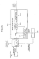
- FIG. 1 is a schematic diagram of relevant parts of an optical scanner and a photoconductor together with an associated control system of an image forming apparatus according to a first embodiment of the present invention.
- FIG. 2 depicts an internal structure of a laser printer as an example of the image forming apparatus.
- the laser printer includes an optical scanner 2.
- the optical scanner 2 includes a polygon mirror 32, a photoconductor 11, sensors 25 and 26, a time difference measuring unit 57, a magnification correction controller 61, and a write clock generator 58.
- the polygon mirror 32 functions as a deflector that deflects optical beams modulated based on an image signal in the horizontal scanning direction thereby scanning the photoconductor 11 with the optical beams and forming an image on the photoconductor 11.
- the sensors 25 and 26 are situated on positions PO 1 and PO 2 along the horizontal scanning direction on either side of the photoconductor 11 and function as optical beam detectors that respectively detect optical beams deflected by the polygon mirror 32.
- the time difference measuring unit 57 measures the time difference between when the sensor 25 detects the optical beam until when the sensor 26 detects the optical beam.
- the magnification correction controller 61 functions as a magnification correcting unit that corrects magnification of the image on the photoconductor 11 in the horizontal scanning direction based on the time difference measured by the time difference measuring unit 57.
- the write clock generator 58 generates a write clock VCLK.
- the write clock generator 58 includes a PLL. transmitter 58a and a phase controller 58b.
- the PLL transmitter 58a functions as a frequency modulator that performs magnification correction of the image on the photoconductor 11 in the horizontal scanning direction by changing the frequency of the image signal in the unit of a line or in the unit of a plurality of lines.
- the phase controller 58b functions as a phase modulator that performs magnification correction of the image on the photoconductor 11 in the horizontal scanning direction by fixing the frequency and changing the cycle time of a target pixel in the unit of pixel.
- the magnification correction controller 61 also functions as the frequency modulator and the phase modulator.
- the magnification correction controller 61 also functions as a phase adjustment amount-determining unit that determines the magnitude correlation between the phase adjustment amount between the sensors 25 and 26 calculated by the phase modulator by fixing the frequency of the image signal and a threshold.
- a controller 50 which is a microcomputer, controls such that the phase modulator performs magnification correction of an image in the horizontal scanning direction until the phase adjustment amount exceeds a threshold, and once the phase adjustment amount has exceeded the threshold, controls such that the frequency modulator performs magnification correction of the image in the horizontal scanning direction, based on the determination result of the magnification correction controller 61.
- the laser printer forms images by using an electrographic method.
- the configuration for forming images using the electrographic method is shown in FIG. 2.
- the laser printer includes photosensitive drums 11Y, 11M, 11C, and 11K (hereinafter, simply as the photoconductor(s) 11, unless otherwise specified) that functions as image carriers on which an image of respective colors of yellow (Y), magenta (M), cyan (C), and black (B), are formed.
- the photosensitive drums 11Y, 11M, 11C, and 11K are situated with a space therebetween along the direction shown by an arrow A.
- a belt drive 6 drives and moves a transfer carrier belt 60 in the direction shown by the arrow A.
- a development unit 12 is provided corresponding to each of the four photoconductors 11.
- the optical scanner 2 is situated above the four photoconductors 11. Paper feed cassettes 3 and 4 are provided in the lower part of an apparatus body 1 of the laser printer, and a pair of resist rollers 5 and the belt drive 6 are also provided.
- the belt drive 6 functions as a transfer unit.
- the laser printer includes a paper ejection tray 8, a manual feed tray 14, a toner supply container 22, and the like.
- the transfer paper P is carried on a transport route shown by one-dot chain line in FIG. 2, an image is formed thereon, and the transfer paper P is ejected on the paper ejection tray 8.
- the transfer paper P fed from the paper feed cassettes 3, 4, or the manual feed tray 14 is carried to the resist rollers 5, while being guided by a transport guide plate and stopped there temporarily.
- the resist rollers 5 rotate at a predetermined timing. As a result, the resist rollers 5 carry the transfer paper P onto the transfer carrier belt 60. The transfer paper P gets electrostatically attracted onto the belt surface. The transfer paper P is then carried to the toner image forming unit, where the photoconductor 11 is present, by the transfer carrier belt 60 that is rotating in the direction shown by the arrow A.
- Toner images of the respective colors formed on the respective photosensitive drums 11Y, 11M, 11C, and 11K are sequentially transferred and superposed on the transfer paper P by an action of transfer electric field and a nip pressure in the toner image forming unit. Accordingly, a full colored toner image is formed on the transfer paper P.
- the surfaces of the photosensitive drums 11Y, 11M, 11C, and 11K are cleaned by respective cleaning units and the electricity is removed therefrom.
- the photosensitive drums 11Y, 11M, 11C, and 11K become ready for formation of next image.
- the fixing unit 7 fixes the full-color toner image onto the transfer paper P.
- the transfer paper P with the fixed full-color toner image is then carried in a first paper ejection direction shown by an arrow B or a second paper ejection direction shown by an arrow C. In which direction the transfer paper P is carried depends on a switching position of a switching guide 21.
- the transfer paper P When the transfer paper P is carried in the first paper ejection direction and ejected onto the paper ejection tray 8, the transfer paper P is ejected in the paper ejection tray 8 in a so-called face down state, with the image surface facing down.
- the transfer paper P When the transfer paper P is carried in the second paper ejection direction, the transfer paper P is carried toward a post-processor (not shown).
- the post-processor can be a sorter, a stapler, or the like.
- a laser diode (LD) 29 that functions as an optical beam generator emits optical beams (laser beams) equivalent of image signals.
- the optical beams pass through a collimate lens and a cylindrical lens, and finally fall on the rotating polygon mirror 32.
- the polygon mirror 32 deflects the optical beams so that optical beams pass through an f ⁇ lens 23 and a toroidal lens (hereinafter, "BTL") (not shown), and fall on the photoconductor 11.
- BTL toroidal lens
- the BTL performs focusing mainly in a vertical scanning direction (i.e., sub scanning direction), that is, performs condensing function and position correction (cross-scan error compensation and the like) in the vertical scanning direction.
- FIG. 1 only one of the four photoconductors 11 is shown.
- the other three photoconductors and corresponding optical scanners have the same configuration, with only the color of an image to be formed being different, and hence the illustration thereof is omitted.
- a driving unit rotates the polygon mirror 32.
- the f ⁇ lens mainly performs velocity transformation. In other words, when optical beams of an isometric velocity that are deflected from the polygon mirror 32 enter into the f ⁇ lens 23, they are converted into optical beams of a constant velocity.
- the optical beam When an optical beam scans the photoconductor 11, the optical beam first falls on the sensor 25, scans the photoconductor 11 in the direction shown by an arrow E, and finally falls on the sensor 26.
- the sensor 25 also serves as a synchronism detection sensor for detecting a laser beam-scanning synchronization signal, which becomes a synchronism detection signal.
- the sensor 25 When an optical beam is detected, the sensor 25 outputs a laser beam detection signal DETP1, and the sensor 26 outputs a laser beam detection signal DETP2.
- the laser beam detection signals DETP1 and DETP2 are transmitted to the time difference measuring unit 57.
- the time difference measuring unit 57 measures a difference between the time of arrival of the laser beam detection signals DETP1 and DETP2. As the polygon mirror 32 rotates, the laser beam detection signals DETP1 and DETP2 arrive one after the other.
- the time difference measuring unit 57 calculates an average of a plurality of measured times as a time difference.
- the time difference measuring unit 57 measures the time of arrival of the laser beam detection signals DETP1 and DETP2 by using timing set by the controller (CPU) 50.
- the time difference measuring unit 57 transmits the time difference to the magnification correction controller 61.
- the magnification correction controller 61 includes a storage unit that stores initial set values and current set values of the set write clock frequency and phase shift value (phase adjustment amount).
- the controller 50 sends the initial set values and the current set values to the magnification correction controller 61.
- the magnification correction controller 61 calculates the phase shift value (phase adjustment amount) when an optimum write clock frequency is set, by using the fact that the image magnification in the horizontal scanning direction is changed by the frequency of the write clock, and by using the fact that the image magnification is changed by shifting the phase in the case of such a short time that cannot be adjusted by adjusting a write clock.
- the magnification correction controller 61 has a function of calculating the optimum phase shift value (phase adjustment amount) by fixing the write clock frequency, and also has a function of comparing the phase shift value calculated with the threshold set by the controller 50, thereby transmitting a write clock setting signal and a control signal for executing the phase shift to the write clock generator 58 at a predetermined timing, respectively.
- the write clock generator 58 includes the PLL transmitter 58a that generates a clock n times as large as a write clock VCLK upon reception of a clock from an oscillator (not shown), and the phase controller 58b having a function of dividing the frequency of a PLL transmission clock by n, synchronized with the laser beam detection signal DETP1 as a synchronism detection signal to generate the write clock VCLK synchronized with the laser beam detection signal DETP1 and having a function of shifting (changing) the write clock cycle time of an optional pixel in the unit of pixel by adding or subtracting an integral multiple of the half cycle of the PLL transmission clock to or from a special cycle of the write clock.
- the write clock generator 58 generates the write clock and executes the phase shift under control of the magnification correction controller 61.
- the write clock VCLK subjected to the image magnification correction in the horizontal scanning due to changeability of the write clock frequency and the phase shift value by the write clock generator 58 is transmitted to an LD modulator 59 that functions as an optical beam generator actuator.
- the LD modulator 59 controls lighting of the laser diode 29 in an LD unit according to the image signal synchronized with the write clock VCLK from the write clock generator 58. Accordingly, laser beams modulated according to the image signal are emitted from the laser diode 29.
- the write clock generator 58 the time difference measuring unit 57, and the magnification correction controller 61 are shown as separate units, they can be combined into one unit.
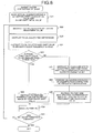
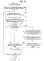
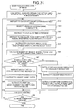
- the image forming apparatus that includes the controller 50 performs a magnification correction of an image based on the flowchart shown in FIG. 3.
- the controller 50 sets a write clock initial value and a phase shift initial value in the magnification correction controller 61. This setting can be performed at a predetermined timing such as when the power is turned on or when r the image forming apparatus is re-used after being stopped. As a result, the optical scanner 2 becomes operable.
- the controller 50 outputs instructions to instruct the time difference measuring unit 57 and the magnification correction controller 61 to calculate a magnification adjustment value.
- the controller instructs the time difference measuring unit 57 to calculate the time difference, and send the time difference to the magnification correction controller 61.
- the controller 50 instructs the magnification correction controller 61 to calculate a phase shift value (phase adjustment amount), when the write clock frequency is fixed, from the time difference.
- the controller 50 instructs the magnification correction controller 61 to calculate a write clock frequency (write clock value) and a phase shift value, when an optimum write clock frequency is set, from the time difference.
- the controller 50 compares the phase shift value (phase adjustment amount) with a preset threshold. In other words, the controller 50 checks whether the phase shift value is equal to or smaller than the threshold, and stores the result (magnitude correlation) in the storage unit.
- step S7 the controller 50 determines that magnification correction of an image is to be executed by phase modulation, and outputs an instruction to that effect to the write clock generator 58.
- the magnification correction of the image can be performed without lengthening the interval between sheets so that the printing does not stop even during continuous printing.
- the controller 50 issues a magnification adjustment instruction to the magnification correction controller 61 at the timing effective for printing after having calculated the phase shift value.
- the controller 50 issues a control signal to the write clock generator 58 so as to perform magnification correction of the image by using the phase shift value calculated at step S4. Accordingly, the magnification correction of the image is performed by phase shifting.
- step S10 the controller 50 determines that magnification correction of the image is to be executed by the frequency modulation and outputs an instruction to that effect to the write clock generator 58.
- magnification correction is performed by changing the write clock frequency (frequency of an image signal) in the unit of a line or in the unit of a plurality of lines.
- magnification correction by the frequency modulation cannot be performed at any timing during image formation, because, this type of correction takes time. In other words, in continuous printing in which time interval between printing of images on two sheets is short, magnification correction by the frequency modulation cannot be performed. As a result, if the continuous printing is being performed, the printing is temporarily suspended, and at step S11, the controller 50 issues a magnification adjustment instruction to the magnification correction controller 61.
- the controller 50 issues a control sigal to the write clock generator 58 so as to perform magnification correction of the image with optimum write clock frequency and phase shift value that are calculated at step S5. Accordingly, magnification correction of the image is performed by frequency modulation.
- step S13 printing is executed according to a control signal set and transmitted to the write clock generator 58 at step S9, or the control signal set and transmitted to the write clock generator 58 at step S12.
- step S14 the controller 50 determines whether the all the images have been formed. If all the images have been formed, the process procedure is finished. If some of the images have not been formed yet, the system control returns to step S2, and the same process procedure is repeated for the remaining images.
- magnification correction of an image is performed by changing the cycle time of an optional pixel in the unit of pixel until the phase adjustment value (phase shift value) exceeds the preset threshold, and after the phase adjustment value exceeds the preset threshold, magnification correction of the image is performed by changing the frequency of the image signal in the unit of a line or in the unit of a plurality of lines.
- phase adjustment value phase shift value
- magnification correction of the image is performed by changing the frequency of the image signal in the unit of a line or in the unit of a plurality of lines.
- FIG. 4 is a flowchart of a process procedure for the magnification correction of an image performed by a control system in an image forming apparatus according to a second embodiment of the present invention.
- the configuration of the image forming apparatus according to the second embodiment is the same as that in FIG. 2.
- the configuration of the control system and the scanner is the same as that in FIG. 1, but only the content of the control performed by the controller (CPU) is different. Therefore, illustrations of the configuration of the image forming apparatus and the control system are omitted as well, and as required, explanation is given by using the reference signs used in FIG. 1.
- the steps S1 to S4 in FIG. 4 are the same as those in FIG. 3.
- the step S5 is performed after the step S6 but before the step S10.
- FIG. 5 is a schematic diagram of relevant parts of an optical scanner and a photoconductor together with an associated control system of an image forming apparatus according to a third embodiment of the present invention
- FIG. 6 is a flowchart of a process procedure for a magnification correction of an image performed by the control system.
- the parts that are similar to those shown in FIG. 1 have been designated with like reference signs.
- the configuration of the image forming apparatus according to the third embodiment is the same as that in FIG. 2.
- the image forming apparatus according to the third embodiment is different from the image forming apparatus according to the first embodiment in that a controller (CPU) 50' is provided instead of the controller 50, and the magnification correction controller 61 is not provided.
- the controller 50' is a microcomputer same as the controller 50, and performs the functions of both the controller 50 and the magnification correction controller 61.
- the time difference measuring unit 57 performs time difference measurement and calculation between the laser beam detection signals DETP1 and DETP 2, and transmits the measurement result and the calculation result to the controller 50'.
- the controller 50' has a storage unit that stores the initial set values and the current set values of the write clock frequency and the phase shift value (phase adjustment amount), and has a function of calculating an optimum write clock frequency and a phase shift value by using the fact that the image magnification in the horizontal scanning direction is changed by the frequency of the optimum write clock, and by using the fact that the image magnification is changed by shifting the phase in the case of such a short time that cannot be adjusted by adjusting a write clock.
- the controller 50' has a function of calculating the optimum phase shift value (phase adjustment amount) by fixing the write clock frequency, and also has a function of comparing the phase shift value calculated with the preset threshold, thereby transmitting a write clock setting signal and a control signal for executing the phase shift to the write clock generator 58 at a predetermined timing respectively.
- the controller 50' functions as the phase adjustment amount-determining unit.
- the controller 50' also functions as a frequency modulator together with the PLL transmitter 58a, and as a phase modulator together with the phase controller 58b.
- the write clock generator 58 and the time difference measuring unit 57 are shown as separate units; however, they can be combined in one unit.
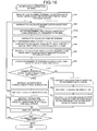
- the image forming apparatus that includes the controller 50' performs a magnification correction of an image based on the flowchart shown in FIG. 6.
- the controller 50' sets a write clock initial value and a phase shift initial value in the write clock generator 58.
- This setting can be performed at a predetermined timing such as when the power is turned on or when r the image forming apparatus is re-used after being stopped. As a result, the optical scanner 2 becomes operable.
- the controller 50' outputs an instruction to the time difference measuring unit 57 to calculate a magnification adjustment value.
- the controller 50' instructs the time difference measuring unit 57 to calculate the time difference, and send the time difference to the controller 50'.
- the controller 50 calculate a phase shift value (phase adjustment amount), when the write clock frequency is fixed, from the time difference received from the time difference measuring unit 57.
- the controller 50' compares the phase shift value (phase adjustment amount) with a preset threshold, and stores the result (magnitude correlation) in the storage unit.
- step S26 the controller 50' determines that magnification correction of an image is to be executed by phase modulation, and outputs an instruction to that effect to the write clock generator 58.
- step S27 the controller 50' calculates a write clock frequency and a phase shift value, when an optimum write clock frequency is set, from the time difference.
- the controller 50' outputs to the write clock generator 58 a control signal for performing magnification correction of an image based on the write clock frequency and the phase shift value.
- the controller 50' sends a control signal for performing magnification correction of an image based on the write clock frequency and the phase shift value calculated at step S27 to the write clock generator 58. Accordingly, magnification correction of the image is performed by the frequency modulation.
- magnification correction by frequency modulation the write clock is changed, and hence, magnification correction cannot be performed at any timing during image formation. Further, since a certain period of time is necessary for the magnification correction processing, it is necessary to have an interval between sheets during continuous printing. Accordingly, continuous printing is temporarily suspended, and the control signal is sent to the write clock generator 58 at a convenient timing.
- step S30 printing is executed at the write clock frequency, with the write clock frequency changed according to the control signal set and transmitted to the write clock generator 58 at step S26, or the control signal set and transmitted to the write clock generator 58 at step S29.
- step S31 the controller 50' determines whether the all the images have been formed. If all the images have been formed, the process procedure is finished. If some of the images have not been formed yet, the system control returns to step S22, and the same process procedure is repeated for the remaining images.
- FIG. 7 is a schematic diagram of relevant parts of an optical scanner and a photoconductor together with an associated control system of an image forming apparatus according to a fourth embodiment of the present invention
- FIG. 8 is a flowchart of a process procedure for a magnification correction of an image performed by the control system.
- the parts that are similar to those shown in FIG. 1 have been designated with like reference signs.
- the steps that are similar to those shown in FIG. 3 have been designated with like step numbers.
- the configuration of the image forming apparatus according to the fourth embodiment is the same as that in FIG. 2.
- the image forming apparatus is different from the image forming apparatus according to the first embodiment in that a write start position Ps in the horizontal scanning direction shown in FIG. 7 can be corrected by a write start position-correcting phase adjustment amount (hereinafter, as write position-correcting phase shift value), and magnification in the horizontal scanning direction can be also corrected by a magnification-correcting phase adjustment amount in the horizontal scanning direction (hereinafter, as magnification-correcting phase shift value), and that magnitude correlation between the magnification-correcting phase shift value and the set threshold is then determined, and until the magnification-correcting phase shift value as the determination result exceeds the threshold, magnification correction of an image is performed by phase modulation calculated by fixing the frequency of an image signal, and after the magnification-correcting phase shift value exceeds the threshold, magnification correction of the image is performed by frequency modulation.
- a write start position Ps in the horizontal scanning direction shown in FIG. 7 can be corrected by a write start position-correcting phase adjustment amount (hereinafter, as write position-
- a magnification correction controller 61' has a configuration including a storage unit that stores the initial set values of the write clock frequency transmitted from a controller (CPU) 50", the write position-correcting phase shift value in the horizontal scanning direction, and the magnification-correcting phase shift value, as well as the current set values.
- the controller (CPU) 50" is a microcomputer that starts the routine for a magnification correction of an image shown in FIG. 8, at a predetermined timing such as after turning the power on or restarting after having stopped the machine.
- the controller 50" sets an initial value of the write clock frequency, an initial value of the write position-correcting phase shift value (write position-correcting phase shift initial value), and an initial value of the magnification-correcting phase shift value (magnification-correcting phase shift initial value) in the magnification correction controller 61', at a predetermined timing such as after turning the power on or restarting after having stopped the machine.
- the controller 50" makes the optical scanner 2 printable corresponding to the set initial value of the write clock frequency and phase shift initial values. In this state, since the printing is possible, printing can be performed.
- Steps S2 and S3 are same as the steps S2 and S3 shown in FIG. 3.
- the magnification correction controller 61' calculates the write position-correcting phase shift value in the horizontal scanning direction and the magnification-correcting phase shift value when the write clock frequency is fixed, from a mean value or the like of the measurement result of the time difference since the sensor 25 has detected the laser beam until the sensor 26 detects the laser beam.
- the magnification correction controller 61' calculates a write clock value (frequency) and a magnification-correcting phase shift value when an optimum write clock frequency is set, from the mean value or the like of the measurement result of the time difference.
- the controller 50 determines the magnitude correlation between the magnification-correcting phase shift value calculated at step S4' and the threshold preset in the controller 50", that is, whether the magnification-correcting phase shift value is equal to or smaller than the threshold, and stores the comparison result (magnitude correlation) in the storage unit.
- magnification-correcting phase shift value is equal to or smaller than the threshold, that is, when the magnification-correcting phase shift value does not exceed the threshold (YES)
- the same processing and determination as those in FIG. 3 are performed at step S7 and following steps, to perform magnification correction of an image by phase modulation, with the frequency fixed.
- magnification correction in the horizontal scanning direction is performed only by using the magnification-correcting phase shift value.
- magnification-correcting phase shift value is larger than the threshold, that is, the magnification-correcting phase shift value exceeds the threshold
- same processing and determination as those in FIG. 3 are performed at step S10 and following steps, to perform magnification correction of the image by frequency modulation, in which magnification correction is performed by changing the frequency of an image signal to an optimum write clock frequency in the unit of a line or in the unit of a plurality of lines.
- the phase adjustment amount (phase shift) at the time of fixing the write clock frequency is divided into the write position-correcting phase shift value for correcting the write start position and the magnification-correcting phase shift value for correcting the magnification in the horizontal scanning direction. Only the magnification-correcting phase shift value is compared with the thre.shold to determine the magnitude correlation therebetween, and magnification correction of the image by phase modulation and magnification correction of the image by frequency modulation are changed over to each other according to the determination result. Even when the changeover of the image magnification correction method is determined based on only the magnification-correcting phase shift value, there is no problem because the write position-correcting phase shift value affects little on image degradation in the image area.
- Magnification correction of the image by the frequency modulation in which the image forming operation needs to be suspended temporarily, is executed only when the magnification-correcting phase shift value exceeds the threshold.
- the number of executing the magnification correction of the image by the frequency modulation can be reduced, thereby improving the overall print speed (productivity of image formation) accordingly, as the whole image forming apparatus.
- the magnification correction controller 61' shown in FIG. 7 may not be provided.
- the configuration of the image forming apparatus according to the fifth embodiment is the same as that in the third embodiment explained with reference to FIG. 5.
- the time difference measuring unit 57 shown in FIG. 7 performs time difference measurement and calculation between the laser beam detection signals DETP1 and DETP2, and transmits the measurement result and calculation result to the controller 50".
- the controller 50" has a configuration including a storage unit that stores respective initial set values and current set values of the write clock frequency, the magnification-correcting phase shift value, and the write position-correcting phase shift value.
- the controller 50" has a function of calculating an optimum write clock frequency, and a magnification-correcting phase shift value and a write position-correcting phase shift value at the optimum frequency, a function of calculating an optimum magnification-correcting phase shift value by fixing the write clock frequency, and a function of comparing the calculated magnification-correcting phase shift value with the preset threshold, and transmits a write clock setting signal and a control signal for performing phase shift to the write clock generator 58 at a predetermined timing, respectively.
- FIG. 9 is a flowchart of a process procedure for a magnification correction of an image performed by a control system in an image forming apparatus according to a sixth embodiment of the present invention.
- FIG. 9 the steps that are similar to those shown in FIG. 8 have been designated with like step numbers.
- the configuration of the image forming apparatus according to the sixth embodiment is the same as that in FIG. 2.
- the control system is the same as that of the fourth embodiment explained with reference to FIG. 7 (or may be configured as shown in FIG. 5), and only the content of the control performed by the control system is different. Therefore, illustration of the control system is omitted as well, and as required, explanation is given by using the reference signs used in FIG. 7.
- the phase modulator in the image forming apparatus can correct the write start position in the horizontal scanning direction by a write position-correcting phase shift value (write start position-correcting phase adjustment amount), and the magnification in the horizontal scanning direction by a magnification-correcting phase shift value (magnification-correcting phase adjustment amount in the horizontal scanning direction), respectively, as in the fourth embodiment explained with reference to FIG. 7 and FIG. 8.
- a phase adjustment amount-determining unit determines the magnitude correlation between a phase shift value (phase adjustment amount) and a set threshold, the phase shift value being obtained by adding up the write position-correcting phase shift value and the magnification-correcting phase shift value (similar to those explained in the fourth embodiment). Based on the determination result, until the phase adjustment amount exceeds the threshold, magnification correction of an image in the horizontal scanning direction is performed by phase modulation in which the write clock frequency is fixed, and after the phase adjustment amount exceeds the threshold, magnification correction of the image in the horizontal scanning direction is performed by frequency modulation, in which the write clock frequency is changed to an optimum value.
- the controller (the same microcomputer as the controller 50" in FIG. 7) of the image forming apparatus according to the sixth embodiment performs the same processing as at step S1' in FIG. 8, to set a write clock initial value, a write position-correcting phase shift initial value, and a magnification-correcting phase shift initial value, thereby making the optical scanner printable according to the set write clock initial value and phase shift initial values.
- the controller performs the same processing as at steps S2 and S3 in FIG. 8, and at step S4', calculates the write position-correcting phase shift value in the horizontal scanning direction when the write clock frequency is fixed and the magnification-correcting phase shift value, from a mean value or the like of the measurement result of the time difference since the sensor 25 has detected the laser beam until the sensor 26 detects the laser beam, as in the fourth embodiment.
- the magnification correction controller 61' calculates a write clock value (frequency) and a magnification-correcting phase shift value when an optimum write clock frequency is set, from the mean value or the like of the measurement result of the time difference.
- the controller determines whether the phase adjustment amount i.e., the total of the phase shift values is equal to or smaller than the set threshold, the phase adjustment amount being obtained by adding up the write position-correcting phase shift value and the magnification-correcting phase shift value when the write clock frequency is fixed, calculated at step S4', and stores the determination result (magnitude correlation) in the storage unit.
- the same processing and determination as those in FIG. 8 are performed at step S7 and following steps, to perform magnification correction of an image by phase modulation, with the frequency fixed.
- step S6 when the total of the phase shift values is larger than the threshold, that is, the total of the phase shift values exceeds the threshold, the same processing and determination as those in FIG. 8 are performed at step S10 and following steps, to perform magnification correction of the image by frequency modulation, in which magnification correction is performed by changing the frequency of an image signal to an optimum write clock frequency in the unit of a line or in the unit of a plurality of lines.
- magnification correction of an image by phase modulation (fixed frequency) and magnification correction of the image by frequency modulation are changed over to each other according to whether the phase shift value, obtained by adding up the write position-correcting phase shift value and the magnification-correcting phase shift value when the write clock frequency is fixed, exceeds the preset threshold.
- phase adjustment amount (phase shift value) can be determined accurately. Accordingly, changeover to the magnification correction of the image by frequency modulation can be performed with high accuracy, thereby enabling accurate prevention of image degradation.
- FIG. 10A and FIG. 10B are explanatory views of region dividing in the horizontal scanning direction performed by an image forming apparatus according to a seventh embodiment of the present invention
- FIG. 11 is a flowchart of a process procedure for a magnification correction of an image performed by a control system in the image forming apparatus according to the seventh embodiment.
- the configuration of the image forming apparatus according to the seventh embodiment is the same as that in FIG. 2.
- the control system is the same as that of the first embodiment explained with reference to FIG. 1 (or may be configured as shown in FIG. 5), and only the content of the control performed by the control system is different. Therefore, illustration of the control system is omitted as well, and as required, explanation is given by using the reference signs used in FIG. 1.
- the image forming apparatus is different from that of the first embodiment in that the phase adjustment amount-determining unit (the magnification correction controller 61 in FIG. 1) determines the magnitude correlation between a phase adjustment amount in a predetermined region in the horizontal scanning direction calculated by the phase modulator (the phase controller 58b in FIG. 1) and a set threshold, and that, based on the determination result of the phase adjustment amount-determining unit, magnification correction of an image by the phase modulator is changed over to magnification correction of the image by the frequency modulator (the PLL transmitter 58a in FIG. 1).
- the phase adjustment amount-determining unit determines the magnitude correlation between a phase adjustment amount in a predetermined region in the horizontal scanning direction calculated by the phase modulator (the phase controller 58b in FIG. 1) and a set threshold, and that, based on the determination result of the phase adjustment amount-determining unit, magnification correction of an image by the phase modulator is changed over to magnification correction of the image by the frequency modulator (the PLL transmitter 58a in FIG. 1).
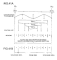
- predetermined regions in the horizontal scanning direction that is, the whole region between detection positions PO 1 and PO 2 of the sensors 25 and 26 as shown in FIG. 10A (also see FIG. 1) is divided into a plurality of regions, for example, into ten (1 to 10) regions in the horizontal scanning direction, corresponding to the magnification fluctuation characteristic of the f ⁇ lens and the printing size width according to an assumed transfer paper size.
- the phase shift value for each divided region that is, the phase shift value (phase adjustment amount), calculated by fixing the write clock frequency, is set for each region as shown in Table 1.
- magnification correction controller 61 and the controller 50 set the thresholds I to X corresponding to the respective regions as shown in Table 1, and calculate the phase shift values I to X and store these values.
- Determination of the magnitude correlation between the phase shift value and the threshold is performed in the following manner.
- phase shift values I to X are compared with corresponding thresholds I to X for each region of the divided first to the tenth regions.
- the regions are then divided into a region in which the phase shift value is equal to or smaller than the threshold, and a region in which the phase shift value is larger than the threshold.
- magnification correction of an image is performed by frequency modulation in which the magnification correction is performed by changing the frequency of an image signal to an optimum write clock frequency in the unit of a line or in the unit of a plurality of lines.
- FIG. 10A and FIG. 10B there is shown an example in which predetermined regions in the horizontal scanning direction indicate a plurality of divided regions having an unequal width, corresponding to the magnification fluctuation characteristic of the f ⁇ lens and the printing size width according to an assumed transfer paper size.
- the respective regions to be divided may be divided into regions having an equal width.
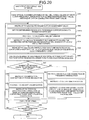
- the image forming apparatus starts the routine of magnification correction of an image shown in FIG. 11, at a predetermined timing.
- the controller 50 sets a write clock frequency initial value (hereinafter, simply as write clock initial value) and a phase shift initial value in the magnification correction controller 61, at a predetermined timing such as after turning the power on or restarting after having stopped the machine.
- a write clock frequency initial value hereinafter, simply as write clock initial value
- a phase shift initial value in the magnification correction controller 61
- the optical scanner is made printable corresponding to the set write clock initial value and phase shift initial value.
- step S42 the same processing as explained at step S2 in FIG. 3 is performed, to issue an instruction to calculate a magnification adjustment value.
- step S43 the same processing as explained at step S3 in FIG. 3 is performed, to perform measurement of the time difference since the sensor 25 has detected the laser beam until the sensor 26 detects the laser beam for a specified number of times, so that a mean value or the like of the measurement result is calculated.
- phase shift value (phase adjustment amount) is calculated for each region when the write clock frequency is fixed, from the mean value or the like of the measurement result of the time difference.
- a write clock frequency (write clock value) when an optimum write clock frequency is set is calculated from the mean value or the like of the measurement result of the time difference. Further, a phase shift value (phase adjustment amount) for each region when the frequency is changed to the optimum write clock frequency is calculated.
- the phase shift value (a value calculated by fixing the write clock frequency) is compared with each of the thresholds I to X (see Table 1) corresponding thereto for each region, to calculate the number of regions in which the phase shift value is larger than the threshold.
- step S47 it is determined whether the number of regions in which the phase shift value is larger than the threshold is equal to or smaller than a preset value, and if the number is equal to or smaller than the preset value (YES), control proceeds to steps S48 and S49, to transmit a determination result such that magnification correction of an image is to be executed by phase modulation that can perform magnification correction of the image without expanding the interval between sheets even during continuous printing, as in the processing explained at steps S7 and S8 in FIG. 3, to issue a magnification adjustment instruction.
- the controller 50 issues an instruction for performing magnification correction of an image with the respective phase shift values when the write clock frequency is fixed, calculated for respective regions. Accordingly, magnification correction of the image is performed by changing the cycle time of an optional pixel in the unit of pixel.
- step S47 when control proceeds to step S51 since the number of regions in which the phase shift value is larger than the threshold exceeds the preset value, the same processing as explained at steps S10 and S11 in FIG. 3 is performed at steps S51 and S52 to transmit a determination result such that magnification correction of an image is to be executed by frequency modulation in which magnification correction of the image is performed by changing the write clock frequency (frequency of an image signal) in the unit of a line or in the unit of a plurality of lines, to issue a magnification adjustment instruction.
- the controller 50 issues an instruction for performing magnification correction of an image based on the optimum write clock frequency and the phase shift value for each region calculated at step S45.
- the magnification correction of an image is performed by frequency modulation, in which the frequency of an image signal is changed in the unit of a line or in the unit of a plurality of lines.
- FIG. 11 indicates an example in which the phase shift value for each region when the write clock frequency is fixed, and the phase shift value for each region when an optimum write clock frequency is set are respectively calculated, before determining whether the number of regions in which the phase shift value is larger than the threshold is equal to or smaller than the preset value.
- the calculation of the phase shift value for each region when the optimum write clock frequency is set is not performed at step S45 in FIG. 11, but the processing at step S45 may be performed at steps prior to step S51 and only when the number of regions in which the phase shift value is larger than the threshold exceeds the preset value (NO as determination result) in the determination at step S47.
- the comparison between the phase shift value and the threshold may be performed in such a manner that, as shown in Table 2, a threshold obtained by unifying a plurality of divided regions is provided, which is then compared with a phase shift value obtained in the above manner. For example, even when the phase shift value is set for each region of from the first to the tenth regions, as in the example shown in Table 2, the respective regions are unified into a group (region) of from the second to the fourth regions, a group (region) of from the fifth to the sixth regions, and a group (region) of from the seventh to the ninth regions, and total values II, III, and IV of the phase shift values are respectively set corresponding to the groups, and these can be compared with the respective thresholds II, III, and IV.
- Each group (region) is obtained by unifying a plurality of regions, and the number of groups in which the phase shift value exceeds the corresponding threshold is calculated.
- magnification correction of an image is performed by frequency modulation, which is performed by changing the write clock frequency.
- the magnification correction controller 61 (or the controller 50' when applied to FIG. 5) has a function of calculating a phase shift value for each group shown in Table 2, and storing the calculation result. Further, the magnification correction controller 61 also includes a storage unit in which a threshold for each group can be set.
- the predetermined regions in the horizontal scanning direction obtained by dividing the whole region in the horizontal scanning direction can be positioned in a horizontal-scanning image area, as the second to the ninth regions shown in FIG. 10B.
- the phase shift value (phase adjustment amount) in the image area can be then monitored, and hence, image degradation in the image area can be prevented.
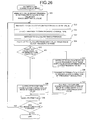
- FIG. 12 is a flowchart of a process procedure for a magnification correction of an image performed by a control system in an image forming apparatus according to an eighth embodiment of the present invention.
- FIG. 12 the steps that are similar to those shown in FIG. 11 have been designated with like step numbers.
- the configuration of the image forming apparatus according to the eight embodiment is the same as that in FIG. 2.
- the control system is also the same as that of the fourth embodiment explained with reference to FIG. 7 (or may be configured as shown in FIG. 5), and only the content of the control performed by the control system is different. Therefore, illustration of the control system is omitted as well, and as required, explanation is given by using the reference signs used in FIG. 7.
- the phase modulator in the image forming apparatus can respectively correct the write start position in the horizontal scanning direction by a write position-correcting phase shift value (write start position-correcting phase adjustment amount) by the phase modulation, and magnification in the horizontal scanning direction by a magnification-correcting phase shift value (magnification-correcting phase adjustment amount in the horizontal scanning direction) by phase modulation.
- the phase adjustment amount-determining unit determines the magnitude correlation between the magnification-correcting phase shift value in a predetermined region in the horizontal scanning direction and a set threshold.
- the controller (a microcomputer similar to the controller 50" in FIG. 7) of the image forming apparatus according to the eighth embodiment performs the same processing as at step S1' in FIG. 8, and at next steps S42 and S43, performs the processing in FIG. 11.
- a magnification-correcting phase shift value and a write position-correcting phase shift value for each region are calculated (see Table 3).
- a write clock frequency (write clock value) when an optimum write clock frequency is set is calculated. Further, a magnification-correcting phase shift value for each region when the optimum write clock frequency is set is calculated.
- Table 3 Region Threshold Write position-correcting phase shift value Magnification-correcting phase shift value 1 I I I 2 II II 3 III III III 4 IV IV 5 V V V 6 VI VI VI VII VII 8 VIII VIII 9 IX IX IX 10 X X X X
- the magnification-correcting phase shift value (a value calculated by fixing the write clock frequency) for each region is compared with each of the thresholds I to X corresponding thereto for each region (see Table 3), to calculate the number of regions in which the magnification-correcting phase shift value in each region is larger than the threshold for that region.
- step S47 it is determined whether the number of regions calculated is equal to or smaller than a preset value, and if it is equal to or smaller than the preset value (YES), control proceeds to steps S48 and S49, to transmit a determination result such that magnification correction of an image is to be executed by phase modulation that can perform magnification correction of the image without expanding the interval between sheets even during continuous printing, as in the processing explained at steps S7 and S8 in FIG. 3, to issue a magnification adjustment instruction.
- the controller 50" issues an instruction for performing magnification correction of an image with the respective magnification-correcting phase shift values when the write clock frequency is fixed, calculated for respective regions. Accordingly, magnification correction of the image is performed by changing the cycle time of an optional pixel in the unit of pixel.
- step S47 when control proceeds to step S51 since the number of regions in which the phase shift value is larger than the threshold exceeds the preset value, the same processing as explained at steps S10 and S11 in FIG. 3 is performed at steps S51 and S52, to transmit a determination result such that magnification correction of an image is to be executed by frequency modulation in which magnification correction of the image is performed by changing the write clock frequency (frequency of an image signal) in the unit of a line or in the unit of a plurality of lines, to issue a magnification adjustment instruction.
- the controller 50" issues an instruction for performing magnification correction of an image based on the optimum write clock frequency and the magnification-correcting phase shift value for each region calculated at step S65. Accordingly, the magnification correction of the image is performed by frequency modulation, in which the frequency of an image signal is changed in the unit of a line or in the unit of a plurality of lines.
- FIG. 12 indicates an example in which the magnification-correcting phase shift value and the write position-correcting phase shift value for each region when the write clock frequency is fixed, and the phase shift value for each region when an optimum write clock frequency is set are respectively calculated, before determining whether the number of regions in which the magnification-correcting phase shift value for each region is larger than the threshold for each region is equal to or smaller than the preset value.
- the calculation of the phase shift value for each region when the optimum write clock frequency is set is not performed at step S65 in FIG. 12, but can be performed at steps prior to step S51 and when the number of regions, in which the phase shift value is larger than the threshold, exceeds the preset value (NO) in the determination at step S47.
- determination to change over the magnification correction of an image from the one by phase modulation to the one by frequency modulation is performed by comparing only the magnification-correcting phase shift value with the threshold, and the write position-correcting phase shift value is not used because it has little influence on image degradation in the image area. Accordingly, the content of the control can be simplified.
- FIG. 13 is a flowchart of a process procedure for a magnification correction of an image performed by a control system in an image forming apparatus according to a ninth embodiment of the present invention.
- FIG. 13 the steps that are similar to those shown in FIG. 12 have been designated with like step numbers.
- the configuration of the image forming apparatus according to the ninth embodiment is the same as that in FIG. 2.
- the control system is the same as that of the fourth embodiment explained with reference to FIG. 7 (or may be configured as shown in FIG. 5), and only the content of the control performed by the control system is different.
- the phase modulator in the image forming apparatus is different from that of the eighth embodiment shown in FIG. 12 only in the following aspect. That is, the phase adjustment amount-determining unit determines the magnitude correlation between a phase adjustment amount, obtained by adding up a write position-correcting phase shift value (write start position phase adjustment amount) and a magnification-correcting phase shift value (magnification phase adjustment amount in the horizontal scanning direction) in a predetermined region in the horizontal scanning direction, and a set threshold.
- the controller (a microcomputer similar to the controller 50" in FIG. 7) of the image forming apparatus according to the ninth embodiment performs the same processing as at step S1' in FIG. 8, and thereafter, the same processing at steps S42, S43, S64, and S65 in FIG. 12 is performed.
- the phase shift value (phase adjustment amount), obtained by adding up the write position-correcting phase shift value and the magnification-correcting phase shift value (a value calculated with the write clock frequency being fixed) calculated for each of 1 to 10 regions shown in Table 3, is compared with each of corresponding thresholds I to X for respective regions, and the number of regions, in which the total of the phase shift values in each region is larger than the threshold in the relevant region, is calculated.
- magnification correction of an image is executed by phase modulation that can perform magnification correction of the image without expanding the interval between sheets even during continuous printing.
- magnification correction of the image is executed by frequency modulation, in which magnification correction of the image is performed by changing the write clock frequency (frequency of an image signal) in the unit of a line or in the unit of a plurality of lines.
- step S65 in FIG. 13 may be performed between step S47 and step S51, rather than being performed immediately after step S64.
- determination to change over magnification correction of an image from the one by phase modulation to the one by frequency modulation is performed by comparing the phase shift value obtained by adding up the write position-correcting phase shift value and the magnification-correcting phase shift value with the threshold, and hence, the phase shift amount in a region in which it is desired to prevent image degradation can be accurately obtained.
- FIG. 14 is a flowchart of a process procedure for a magnification correction of an image performed by a control system of an image forming apparatus according to a tenth embodiment of the present invention.
- FIG. 14 the steps that are similar to those shown in FIG. 11 have been designated with like step numbers.
- the configuration of the image forming apparatus according to the tenth embodiment is the same as that in FIG. 2, and hence, the illustration thereof is omitted.
- the control system is also the same as that of the fourth embodiment explained with reference to FIG. 7 (or may be configured as shown in FIG. 5), and only the content of the control performed by the control system is different.
- the image forming apparatus is different from that of the seventh embodiment explained with reference to FIGs. 10A, 10B, and 11 in that a predetermined region-changing unit (the controller functions as this unit like the controller 50" in FIG. 7) that changes a predetermined region in the horizontal scanning direction corresponding to an image area in the horizontal scanning direction is provided.
- a predetermined region-changing unit the controller functions as this unit like the controller 50" in FIG. 7 that changes a predetermined region in the horizontal scanning direction corresponding to an image area in the horizontal scanning direction is provided.
- the predetermined region in the horizontal scanning direction is changed corresponding to an image area in which image formation is performed.
- the image forming apparatus starts the routine for a magnification correction of an image shown in FIG. 14 at a predetermined timing.
- the same processing and determination as those at step S43 and following steps in FIG. 11 are performed. Accordingly, the predetermined regions in the horizontal scanning direction selected corresponding to the image area in Table 4 (in this example, a plurality of selected regions of from the first to the tenth regions, but it can be one region) are compared with corresponding respective thresholds in Table
- magnification correction of the image is executed by frequency modulation, in which magnification correction of the image is performed by changing the write clock frequency (frequency of an image signal) in the unit of a line or in the unit of a plurality of lines.
- the predetermined regions in the horizontal scanning direction to be monitored can be optimized according to the image area (imaging range), it can be avoided that a phase shift value in an unnecessary region is calculated and that the frequency is changed according to the phase shift value in the unnecessary region. Accordingly, the timing at which the magnification correction of the image is performed by frequency modulation can be accurately controlled, thereby improving the print speed (the number of image formations per unit time).
- FIG. 15 is a flowchart of a process procedure for a magnification correction of an image performed by a control system in an image forming apparatus according to an eleventh embodiment of the present invention.
- the steps that are similar to those shown in FIG. 14 have been designated with like step numbers.
- the configuration of the image forming apparatus according to the eleventh embodiment is the same as that in FIG. 2.
- the control system is the same as that of the fourth embodiment explained with reference to FIG. 7 (or may be configured as shown in FIG. 5) , and only the content of the control performed by the control system is different.
- the image forming apparatus is different from that of the tenth embodiment in that a threshold-changing unit that changes the threshold is provided.
- a controller having the same configuration as that of the controller 50" in FIG. 7 functions as the threshold-changing unit. However, since only the content of the control performed by the controller is different from that of the controller 50", the illustration thereof is omitted.
- the threshold is changed according to the image area in which image formation is performed.
- the processing at steps S41 and S42 in FIG. 14 is performed, and at the next step S42", setting is performed by changing the predetermined region in the horizontal scanning direction according to an image area (imaging size) in which the image formation is to be performed, and the threshold is also set according to the image area.
- predetermined regions (see FIGs. 10A and 10B for ten regions) in the horizontal scanning direction are changed according to the image areas A to E in the horizontal scanning direction, and the thresholds corresponding to the image areas A to E are set as shown in Table 5.
- the predetermined region in the horizontal scanning direction selected corresponding to an image area in Table 5 is compared with each corresponding threshold.
- magnification correction of an image is executed by phase modulation that can perform magnification correction of the image without expanding the interval between sheets even during continuous printing.
- magnification correction of the image is executed by frequency modulation, in which magnification correction of the image is performed by changing the write clock frequency (frequency of an image signal) in the unit of a line or in the unit of a plurality of lines.
- the eleventh embodiment since an optimum monitoring region and an optimum threshold can be selected according to the image area (imaging range), the timing of shifting to the magnification correction of an image by frequency modulation can be accurately controlled. Accordingly, the print speed (the number of image formations per unit time) can be improved.
- Five image areas A to E shown in Table 5 correspond to the predetermined regions in the horizontal scanning direction (respective selected regions of from the first to the tenth regions) as shown in Table 4, but as shown in Table 6, the imaging size in the horizontal scanning direction can be divided into new divided areas i to iii, and thresholds can be provided, as shown in Table 7, corresponding to the respective areas i to iii.
- FIG. 16 is a flowchart of a process procedure for a magnification correction of an image performed by a control system in an image forming apparatus according to a twelfth embodiment of the present invention.
- FIG. 16 the steps that are similar to those shown in FIG. 15 have been designated with like step numbers.
- the configuration of the image forming apparatus according to the twelfth embodiment is the same as that in FIG. 2.
- the control system is the same as that of the fourth embodiment explained with reference to FIG. 7 (or may be configured as shown in FIG. 5), and only the content of the control performed by the control system is different.
- the image forming apparatus is different from that of the eleventh embodiment in that a threshold-changing unit (a controller having the same configuration as that of the controller 50" in FIG. 7 functions as this unit) that changes the threshold corresponding to a transfer paper size is provided.
- a threshold-changing unit a controller having the same configuration as that of the controller 50" in FIG. 7 functions as this unit
- the image forming apparatus When the routine for a magnification correction of an image shown in FIG. 16 is started at a predetermined timing, the image forming apparatus performs the processing at steps S41 and S42 in FIG. 15, and at the next step S42a, the image forming apparatus changes the predetermined region in the horizontal scanning direction according to a transfer paper size selected, and sets the threshold corresponding to an image area determined corresponding to the transfer paper size.
- Table 8 Image area Transfer paper size Predetermined region A Business card 5, 6 B A6 vertical 4, 5, 6, 7 C A6 horizontal, A5 vertical 3, 4, 5, 6, 7, 8 D A5 horizontal, A4 vertical 2, 3, 4, 5, 6, 7, 8, 9 E A4 horizontal, A3 vertical 1, 2, 3, 4, 5, 6, 7, 8, 9, 10
- a predetermined region (respective selected regions of from the first to the tenth regions) in the horizontal scanning direction selected corresponding to the image area in Table 5 is then compared with corresponding respective thresholds.
- magnification correction of an image is executed by phase modulation that can perform magnification correction of the image without expanding the interval between sheets even during continuous printing.
- magnification correction of the image is executed by frequency modulation, in which magnification correction of the image is performed by changing the write clock frequency (frequency of an image signal) in the unit of a line or in the unit of a plurality of lines.
- a region in which it is desired to prevent image degradation can be changed corresponding to the transfer paper size.
- the threshold changed by the threshold-changing unit is changed according to the image area in which the image formation is performed.
- the threshold changed by the threshold-changing unit is changed according to the transfer paper size to be used.
- the threshold can be changed according to cumulative time of the image forming operation, the number of image formations, or the temperature in the image forming apparatus.
- an optimum threshold agreeing with the use condition can be set, and hence, the shift from the magnification correction of an image by phase modulation to the magnification correction of the image by frequency modulation can be executed at optimum timing.
- FIG. 17 is a flowchart of a process procedure for a magnification correction of an image performed by a control system in an image forming apparatus according to a thirteenth embodiment of the present invention.
- FIG. 17 the steps that are similar to those shown in FIGS. 12 and 15 have been designated with like step numbers.
- the configuration of the image forming apparatus according to the thirteenth embodiment is the same as that in FIG. 2.
- the control system is the same as that of the fourth embodiment explained with reference to FIG. 7 (or may be configured as shown in FIG. 5), and only the content of the control performed by the control system is different.
- the phase modulator (though not shown, a phase controller similar to the phase controller 58b in FIG. 7 functions as the phase modulator) in the image forming apparatus according to the thirteenth embodiment can respectively correct the write start position in the horizontal scanning direction by a write start position-correcting phase adjustment amount by phase modulation, and magnification in the horizontal scanning direction by a magnification-correcting phase adjustment amount in the horizontal scanning direction by phase modulation.
- the phase adjustment amount-determining unit (though not shown, a magnification correction controller similar to the magnification correction controller 61 in FIG. 7 functions as this unit) determines the magnitude correlation between the magnification-correcting phase adjustment amount in a predetermined region in the horizontal scanning direction (ten regions shown in FIGs. 10A and 10B) and a set threshold.
- the predetermined region in the horizontal scanning direction (In FIG. 17, due to the limitation of space, described as the predetermined region) and the threshold are changed corresponding to the image area as in the eleventh embodiment.
- the controller when the routine for a magnification correction of an image shown in FIG. 17 is started at a predetermined timing, the controller performs the processing at steps S41' and S42 in FIG. 12, and thereafter at step S42", performs the same processing as that in FIG. 15, to set a predetermined region in the horizontal scanning direction corresponding to an image area (imaging size) as well as a threshold corresponding to the image area.
- the controller performs the processing and determination at step S43 and following steps in FIG. 12. Accordingly, comparison is made between the magnification-correcting phase shift value (a value calculated with the write clock frequency being fixed) in the predetermined region (a region selected from 1 to 10 regions shown in Table 5) set corresponding to the image area and the threshold set corresponding to the image area, to calculate the number of regions in which the magnification-correcting phase shift value in each region is larger than the threshold in the region.
- the magnification-correcting phase shift value a value calculated with the write clock frequency being fixed
- magnification correction of an image is executed by phase modulation that can perform magnification correction of the image without expanding the interval between sheets even during continuous printing.
- magnification correction of the image is executed by frequency modulation, in which magnification correction of the image is performed by changing the write clock frequency (frequency of an image signal) in the unit of a line or in the unit of a plurality of lines.
- the phase shift amount (phase adjustment amount) in the predetermined region in the horizontal scanning direction set corresponding to the image area becomes an accurate phase shift amount without being affected by the correction of the write start position, and this amount is compared with an optimum threshold set corresponding to the image area, to control the changeover timing to the magnification correction of an image by the frequency modulation. Accordingly, the magnification correction of the image can be changed over to the frequency modulation at accurate timing, thereby further improving the print speed (the number of image formations per unit time).
- FIG. 18 is a flowchart of a process procedure for a magnification correction of an image performed by a control system in an image forming apparatus according to a fourteenth embodiment of the present invention.
- the steps that are similar to those shown in FIGS. 9 and 15 have been designated with like step numbers.
- the configuration of the image forming apparatus according to the fourteenth embodiment is the same as that in FIG. 2.
- the control system is the same as that of the fourth embodiment explained with reference to FIG. 7 (or may be configured as shown in FIG. 5), and only the content of the control performed by the control system is different.
- the phase modulator (though not shown, a phase controller similar to the phase controller 58b in FIG. 7 functions as the phase modulator) in the image forming apparatus according to the fourteenth embodiment can respectively correct the write start position in the horizontal scanning direction by a write start position-correcting phase adjustment amount by phase modulation, and magnification in the horizontal scanning direction by a magnification-correcting phase adjustment amount in the horizontal scanning direction by phase modulation.
- the phase adjustment amount-determining unit (though not shown, a magnification correction controller similar to the magnification correction controller 61 in FIG.
- the predetermined region in the horizontal scanning direction (In FIG. 18, due to the limitation of space, described as the predetermined region) and the threshold are changed corresponding to an image area.
- the controller when the routine for a magnification correction of an image shown in FIG. 18 is started at a predetermined timing, the controller performs the processing at steps S41' and S42 in FIG. 13, and thereafter at step S42", performs the same processing as that in FIG. 15, to set a predetermined region in the horizontal scanning direction corresponding to an image area (imaging size) as well as a threshold corresponding to the image area.
- the controller performs the processing and determination at step S43 and following steps in FIG. 13.
- the phase shift value phase adjustment amount
- the magnification-correcting phase shift value a value calculated with the write clock frequency being fixed
- magnification correction of an image is executed by phase modulation that can perform magnification correction of the image without expanding the interval between sheets even during continuous printing.
- magnification correction of the image is executed by frequency modulation, in which magnification correction of the image is performed by changing the write clock frequency (frequency of an image signal) in the unit of a line or in the unit of a plurality of lines.
- the determination whether to change over magnification correction of an image from the one by phase modulation to the one by frequency modulation is performed by comparing the phase shift value obtained by adding up the write position-correcting phase shift value and the magnification-correcting phase shift value with the threshold.
- the magnification-correcting phase shift value is calculated based on an optimum predetermined region in the horizontal scanning direction set corresponding to an image area, and the threshold is also set to an optimum value corresponding to the image area. Accordingly, image degradation can be prevented more reliably.
- FIG. 19 is a flowchart of a process procedure for a magnification correction of an image performed by a control system in an image forming apparatus according to a fifteenth embodiment of the present invention.
- FIG. 19 the steps that are similar to those shown in FIGS. 16 and 17 have been designated with like step numbers.
- the configuration of the image forming apparatus according to the fifteenth embodiment is the same as that in FIG. 2.
- the control system is the same as that of the fourth embodiment explained with reference to FIG. 7 (or may be configured as shown in FIG. 5), and only the content of the control performed by the control system is different.
- the phase modulator (though not shown, a phase controller similar to the phase controller 58b in FIG. 7 functions as the phase modulator) in the image forming apparatus according to the fifteenth embodiment can respectively correct the write start position in the horizontal scanning direction by a write start position-correcting phase adjustment amount in a predetermined region in the horizontal scanning direction (any one of ten regions shown in FIGs. 10A and 10B), and magnification in the horizontal scanning direction by a magnification-correcting phase adjustment amount in the horizontal scanning direction in the predetermined region in the horizontal scanning direction.
- the phase adjustment amount-determining unit (though not shown, a magnification correction controller similar to the magnification correction controller 61 in FIG. 7 functions as this unit) determines the magnitude correlation between the magnification-correcting phase adjustment amount in the horizontal scanning direction and a set threshold.
- the predetermined region in the horizontal scanning direction (In FIG. 19, due to the limitation of space, described as the predetermined region) and the threshold are changed corresponding to a transfer paper size as in the twelfth embodiment.
- the controller when the routine for a magnification correction of an image shown in FIG. 19 is started at a predetermined timing, the controller performs the processing at steps S41' and S42 in FIG. 13, and thereafter at step S42a, performs the same processing as that in FIG. 16, to set a predetermined region in the horizontal scanning direction corresponding to a transfer paper size to be used, as well as a threshold corresponding to the transfer paper size.
- the controller performs the processing and determination at step S43 and following steps in FIG. 17. Accordingly, comparison is made between the magnification-correcting phase shift value (a value calculated with the write clock frequency being fixed) in the predetermined region (a region selected from 1 to 10 regions shown in Table 5) set corresponding to the image area, and the threshold set corresponding to the image area, to calculate the number of regions in which the magnification-correcting phase shift value in each region is larger than the threshold in the region.
- the magnification-correcting phase shift value a value calculated with the write clock frequency being fixed
- magnification correction of an image is executed by phase modulation that can perform magnification correction of the image without expanding the interval between sheets even during continuous printing.
- magnification correction of the image is executed by frequency modulation, in which magnification correction of the image is performed by changing the write clock frequency (frequency of an image signal) in the unit of a line or in the unit of a plurality of lines.
- the relation between transfer paper sizes and predetermined regions in the horizontal scanning direction is, for example, the relation shown in Table 8.
- the five image areas A to E respectively correspond to the predetermined regions in the horizontal scanning direction (selected regions from the first to the tenth regions), and the image areas A to E correspond to the respective thresholds as shown in Table 5.
- the transfer paper size may be independently divided in the same manner as that of the imaging size in Table 6, and thresholds respectively corresponding to the divided areas may be set as shown in Table 7.
- a phase shift amount in the selected region that is not affected by correction of the write start position can be obtained, and an optimum monitoring region and threshold can be selected. Accordingly, changeover from the magnification correction of an image by phase modulation to the magnification correction of the image by frequency modulation can be performed at optimum timing, thereby improving the productivity (the print speed) in image formation.
- FIG. 20 is a flowchart of a process procedure for a magnification correction of an image performed by a control system in an image forming apparatus according to a sixteenth embodiment of the present invention.
- FIG. 20 the steps that are similar to those shown in FIGS. 16 and 18 have been designated with like step numbers.
- the configuration of the image forming apparatus according to the sixteenth embodiment is the same as that in FIG. 2.
- the control system is the same as that of the fourth embodiment explained with reference to FIG. 7 (or may be configured as shown in FIG. 5), and only the content of the control performed by the control system is different.
- the phase modulator (though not shown, a phase controller similar to the phase controller 58b in FIG. 7 functions as the phase modulator) in the image forming apparatus according to the sixteenth embodiment can respectively correct the write start position in the horizontal scanning direction by a write start position-correcting phase adjustment amount in a predetermined region in the horizontal scanning direction (any one of ten regions shown in FIGs. 10A and 10B), and magnification in the horizontal scanning direction by a magnification-correcting phase adjustment amount in the horizontal scanning direction in the predetermined region in the horizontal scanning direction.
- the phase adjustment amount-determining unit (though not shown, a magnification correction controller similar to the magnification correction controller 61 in FIG. 7 functions as this unit) determines the magnitude correlation between a phase adjustment amount obtained by adding up the write start position-correcting phase adjustment amount and the magnification-correcting phase adjustment amount in the horizontal scanning direction, and a set threshold.
- the predetermined region in the horizontal scanning direction (In FIG. 20, due to the limitation of space, described as the predetermined region) and the threshold are changed corresponding to a transfer paper size as in the twelfth and fifteenth embodiments.
- the controller when the routine for a magnification correction of an image shown in FIG. 20 is started at a predetermined timing, the controller performs the processing at steps S41' and S42 in FIG. 13, and thereafter at step S42a, performs the same processing as that in FIG. 16, to set a predetermined region in the horizontal scanning direction corresponding to a transfer paper size to be used, as well as a threshold corresponding to the transfer paper size.
- the controller performs the processing and determination at step S43 and following steps in FIG. 13. Accordingly, comparison is made between a phase shift value (phase adjustment amount), obtained by adding up the write position-correcting phase shift value and the magnification-correcting phase shift value (a value calculated with the write clock frequency being fixed) calculated for each region shown in Table 3, and each of thresholds I to X corresponding to respective regions, to calculate the number of regions in which the total of the phase shift values in each region is larger than the threshold in the relevant region.
- phase shift value phase adjustment amount
- magnification correction of an image is executed by phase modulation that can perform magnification correction of the image without expanding the interval between sheets even during continuous printing.
- magnification correction of the image is executed by frequency modulation, in which magnification correction of the image is performed by changing the write clock frequency (frequency of an image signal) in the unit of a line or in the unit of a plurality of lines.
- the determination whether to change over magnification correction of an image from the one by phase modulation to the one by frequency modulation is performed by comparing the phase shift value obtained by adding up the write position-correcting phase shift value and the magnification-correcting phase shift value with the threshold.
- the magnification-correcting phase shift value is calculated according to an optimum predetermined region in the horizontal scanning direction set corresponding to a transfer paper size, and the threshold is also set to an optimum value corresponding to the transfer paper size. Accordingly, image degradation can be prevented more reliably.
- the productivity (the print speed) in image formation can be improved.
- FIG. 21 is a schematic diagram of relevant parts of an optical scanner and a photoconductor together with an associated control system of an image forming apparatus according to a seventeenth embodiment of the present invention
- FIG. 22 is a block diagram of the configuration of a magnification correction controller of the control system of the image forming apparatus according to the seventeenth embodiment
- FIG. 23 is a flowchart of a process procedure for a magnification correction of an image performed by the control system.
- FIG. 21 the parts that are similar to those shown in FIG. 1 have been designated with like reference signs.
- the configuration of the image forming apparatus according to the seventeenth embodiment is the same as that in FIG. 2.
- FIG. 23 the steps that are similar to those shown in FIG. 3 have been designated with like step numbers.
- the image forming apparatus is different from that of the first embodiment in that a magnification correction controller 161 is provided instead of the magnification correction controller 61.
- the magnification correction controller 161 functions as the threshold-changing unit that changes the threshold corresponding to the image type.
- the magnification correction controller 161 includes an image type setting unit 161a, a threshold setting unit 161b, a phase shift/write clock calculator 161c, a write clock/phase shift set value storage unit 161d, and a timing controller 161e.
- the threshold setting unit 161b selects a threshold from a lookup table, i.e., Table 10, according to a signal ("reference value", see Table 9) corresponding to an image type transmitted from the image type setting unit 161a, and sets the threshold.
- a threshold corresponding to the image type is selected.
- the threshold is selected by selecting a reference value corresponding to an image type from Table 9. Specifically, a threshold corresponding to any one of text, photograph, and text and photograph is selected from the lookup table in Table 10.
- the image type is preset by a controller 150 at timing before instructing to calculate a magnification adjustment value.
- step S3 and following steps the same processing and determination as those at step S3 and following steps in FIG. 3 are performed.
- an optimum threshold is selected according to the image type, and until a phase adjustment amount (phase shift value) exceeds the threshold, magnification correction of an image is performed without changing the frequency, but changing the cycle time of an optional pixel in the unit of pixel.
- magnification correction of the image is performed by frequency modulation, in which the magnification correction is performed while suspending continuous printing by changing the frequency of an image signal in the unit of a line or in the unit of a plurality of lines. Accordingly, the number of executing the magnification correction of the image by frequency modulation can be reduced, thereby improving the productivity in image formation accordingly.
- FIG. 24 is a flowchart of a process procedure for a magnification correction of an image performed by a control system in an image forming apparatus according to an eighteenth embodiment of the present invention.
- the steps that are similar to those shown in FIGS. 4 and 23 have been designated with like step numbers.
- the configuration of the image forming apparatus according to the eighteenth embodiment is the same as that shown FIG. 2.
- the configuration of the control system is the same as that in FIG. 21 and FIG. 22, and the content of the control performed by the controller (CPU) is only slightly different. Therefore, the configurations of the image forming apparatus and the control system are omitted.
- a threshold corresponding to an image type is selected. More specifically, by selecting a reference value corresponding to an image type from Table 9, a threshold corresponding to any one of text, photograph, and text and photograph is selected from the lookup table in Table 10.
- step S3 and following steps the same processing and determination as those at step S3 and following steps in FIG. 4 are performed. That is, in the eighteenth embodiment, as in the second embodiment explained with reference to FIG. 4, only when the phase shift value with the write clock fixed is larger than the threshold, a write clock value and a phase shift value when an optimum write clock frequency is set are calculated.
- FIG. 25 is a schematic diagram of relevant parts of an optical scanner and a photoconductor together with an associated control system of an image forming apparatus according to a nineteenth embodiment of the present invention
- FIG. 26 is a flowchart of a process procedure for a magnification correction of an image performed by the control system.
- the parts that are similar to those shown in FIG. 21 have been designated with like reference signs.
- the steps that are similar to those shown in FIGS. 6 and 23 have been designated with like step numbers.
- the configuration of the image forming apparatus according to the nineteenth embodiment is the same as that in FIG. 2.
- the image forming apparatus is different from that of the seventeenth embodiment in that a controller (CPU) 150' performs the function of the magnification correction controller 61 explained with reference to FIG. 21.
- the controller 150' is a microcomputer similar to the controller 150, and only the content of the control is different.
- the time difference measuring unit 57 performs time difference measurement and calculation of the laser beam detection signals DETP1 and DETP2, and transmits the measurement result and the calculation result to the controller 150'.
- the controller 150' has a storage unit that stores initial set values and current set values of the write clock frequency and phase shift value (phase adjustment amount), and has a function of calculating optimum write clock frequency and phase shift value, by using the fact that the image magnification in the horizontal scanning direction is changed by the frequency of the optimum write clock, and by using the fact that the image magnification is changed by shifting the phase in the case of such a short time that cannot be adjusted by adjusting a write clock.
- the controller 150' also has a function of calculating a phase shift value by fixing the write clock frequency, a function of selecting a threshold corresponding to an image type shown in the lookup table in Table 10, and a function of comparing the threshold selected with the phase shift value calculated.
- the controller 150' transmits a write clock setting signal and a control signal for performing the phase shift to the write clock generator 58 at a predetermined timing, respectively.
- the controller 150' serves as the phase adjustment amount-determining unit, and the controller 150' also serves as a modulation content changeover unit.
- the controller 150' also serves as the frequency modulator together with the PLL transmitter 58a and as the phase modulator together with the phase controller 58b.
- the write clock generator 58 and the time difference measuring unit 57 are shown as separate units; however, they can be combined into one write clock generator.
- the controller 150' in the nineteenth embodiment starts the routine for a magnification correction of an image shown in FIG. 26 at a predetermined timing.
- the controller 150' then performs the same processing as that in FIG. 6 at steps S21 and S22.
- a threshold corresponding to an image type is selected, as in the processing explained with reference to FIG. 23. More specifically, by selecting a reference value corresponding to an image type from Table 9, a threshold corresponding to any one of text, photograph, and text and photograph is selected from the lookup table in Table 10.
- step S23 and following steps the same processing and determination as those at step S23 and following steps in FIG. 6 are performed. That is, in the nineteenth embodiment, as in the third embodiment explained with reference to FIG. 6, only when the phase shift value with the write clock fixed is larger than the threshold, a write clock value and a phase shift value when an optimum write clock frequency is set are calculated.
- FIG. 27 is a schematic diagram of relevant parts of an optical scanner and a photoconductor together with an associated control system of an image forming apparatus according to a twentieth embodiment of the present invention
- FIG. 28 is a flowchart of a process procedure for a magnification correction of an image performed by the control system.
- the parts that are similar to those shown in FIG. 25 have been designated with like reference signs.
- the steps that are similar to those shown in FIGS. 8 and 23 have been designated with like step numbers.
- the configuration of the image forming apparatus according to the twentieth embodiment is the same as that in FIG. 2.
- the image forming apparatus according to the twentieth embodiment is different from the image forming apparatus according to the seventeenth embodiment shown in FIG. 21 to FIG. 23 in that correction of the write start position Ps in the horizontal scanning direction shown in FIG. 27 can be performed by a write position-correcting phase shift value (a write start position-correcting phase adjustment amount), and magnification correction in the horizontal scanning direction can be performed by a magnification-correcting phase shift value (a magnification-correcting phase adjustment amount in the horizontal scanning direction), and that magnitude correlation between the magnification-correcting phase shift value and the set threshold is then determined.
- a write position-correcting phase shift value a write start position-correcting phase adjustment amount
- magnification-correcting phase shift value a magnification-correcting phase adjustment amount in the horizontal scanning direction
- magnification correction of an image is performed by phase modulation calculated by fixing the frequency of an image signal, and after the magnification-correcting phase shift value exceeds the threshold, magnification correction of the image is performed by frequency modulation.
- the magnification correction controller 61' has a storage unit that stores initial set values and the current set values of the write clock frequency, the write position-correcting phase shift value in the horizontal scanning direction, and the magnification-correcting phase shift value, transmitted from the controller (CPU) 150".
- the controller (CPU) 150" is a microcomputer, similar to the controller 150 in FIG. 21, which starts the routine for a magnification correction of an image shown in FIG. 28, at a predetermined timing such as after turning the power on or restarting after having stopped the machine.
- the controller 150" then performs the same processing as that shown in FIG. 8 at steps S1' and S2.
- a threshold corresponding to an image type is selected, as explained with reference to FIG. 23. More specifically, by selecting a reference value corresponding to an image type from Table 9, a threshold corresponding to any one of text, photograph, and text and photograph is selected from the lookup table in Table 10.
- step S3 and following steps the same processing and determination as those at step S3 and following steps in FIG. 8 are performed. That is, in the twentieth embodiment, as in the fourth embodiment explained with reference to FIG. 8, only when the magnification-correcting phase shift value with the write clock fixed is larger than the threshold, a write clock value and a phase shift value when an optimum write clock frequency is set are calculated, thereby performing magnification correction of an image by frequency modulation.
- the changeover to the magnification correction of the image by frequency modulation is determined by comparing only the magnification-correcting phase shift value with the threshold. This is because no problem will occur even if the write position-correcting phase shift value is not used because this value has little influence on image degradation in the image area.
- the magnification correction of the image by frequency modulation which requires suspension of the image forming operation, is performed only when the magnification-correcting phase shift value exceeds the threshold.
- the number of executing the magnification correction of the image by frequency modulation can be reduced, thereby improving the overall print speed (productivity in image formation) accordingly, as the whole image forming apparatus.
- FIG. 29 is a flowchart of a process procedure for a magnification correction of an image performed by a control system in an image forming apparatus according to a twenty-first embodiment of the present invention.
- FIG. 29 the steps that are similar to those shown in FIGS. 9 and 23 have been designated with like step numbers.
- the configuration of the image forming apparatus according to the twenty-first embodiment is the same as that in FIG. 2.
- the control system is the same as that of the twentieth embodiment explained with reference to FIG. 27, and only the content of the control performed by the control system is different. Therefore, illustration of the control system is omitted, and it will be explained by using reference signs in FIG. 21 according to need.
- the phase modulator in the image forming apparatus can correct the write start position in the horizontal scanning direction by a write position-correcting phase shift value (write start position-correcting phase adjustment amount), and the magnification in the horizontal scanning direction by a magnification-correcting phase shift value (magnification-correcting phase adjustment amount in the horizontal scanning direction), respectively, as in the sixth embodiment explained with reference to FIG. 9.
- the phase adjustment amount-determining unit determines the magnitude correlation between a phase shift value (phase adjustment amount) and the set threshold, the phase shift value being obtained by adding up the write position-correcting phase shift value and the magnification-correcting phase shift value (similar to those explained in the twentieth embodiment). Based on the determination result, until the phase adjustment amount exceeds the threshold according to the determination result, correction of an image in the horizontal scanning direction is executed by phase modulation in which the write clock frequency is fixed, and after the phase adjustment amount exceeds the threshold, magnification correction of the image in the horizontal scanning direction is executed by frequency modulation, in which the write clock frequency is changed to an optimum value.
- the image forming apparatus starts the routine for a magnification correction of an image shown in FIG. 29 at a predetermined timing.
- the image forming apparatus then performs the same processing as that in FIG. 9 at steps S1' and S2.
- a threshold corresponding to an image type is selected, as explained with reference to FIG. 23. More specifically, by selecting a reference value corresponding to an image type from Table 9, a threshold corresponding to any one of text, photograph, and text and photograph is selected from the lookup table in Table 10.
- step S3 and following steps the same processing and determination as those at step S3 and following steps in FIG. 9 are performed. That is, in the twenty-first embodiment, as in the sixth embodiment explained with reference to FIG. 9, only when the phase shift value obtained by adding up the write position-correcting phase shift value and the magnification-correcting phase shift value when the write clock frequency is fixed is larger than a threshold (Table 10) selected corresponding to an image type, changeover from magnification correction of an image by phase modulation (with frequency fixed) to magnification correction of the image by frequency modulation is performed.
- Table 9 Image type Content Reference value a Text I b Photograph II c Text and photograph III
- phase adjustment amount (phase shift amount) can be accurately determined. Accordingly, changeover to the magnification correction of the image by frequency modulation can be performed highly accurately, and hence, image degradation can be accurately prevented. Further, changeover timing to the magnification correction of the image by frequency modulation can be delayed to the very limit of image degradation that is not acceptable anymore, thereby improving the overall print speed (the productivity in image formation) accordingly, as the whole image forming apparatus.
- FIG. 30 is a flowchart of a process procedure for a magnification correction of an image performed by a control system in an image forming apparatus according to a twenty-second embodiment of the present invention.
- the steps that are similar to those shown in FIG. 11 have been designated with like step numbers.
- the configuration of the image forming apparatus according to the twenty-second embodiment is the same as that in FIG. 2.
- the control system is the same as that of the seventeenth embodiment explained with reference to FIG. 21 (or may be configured as shown in FIG. 25), and only the content of the control performed by the control system is different.
- the image forming apparatus according to the twenty-second embodiment is different from the image forming apparatus according to the seventh embodiment shown in FIG. 11 in that the threshold-changing unit that changes the threshold according to the image type is provided.
- the controller having the same configuration as that of the controller 150 in FIG. 21 functions as the threshold-changing unit, but only the content of the control performed by the controller is different.
- the control system in the image forming apparatus starts the routine for a magnification correction of an image shown in FIG. 30 at a predetermined timing.
- control system then performs the same processing as that in FIG. 11 at steps S41 and S42, and at next step S2c, text, photograph, and text and photograph are made to correspond to image types a to c, respectively, as shown in Table 9, as in the processing explained with reference to FIG. 23.
- the threshold corresponding to the selected image type is selected from the lookup table in.Table 10.
- step S43 and following steps the same processing and determination as those at step S43 and following steps in FIG. 11 are performed.
- the phase shift value is compared with the threshold selected from Table 10 for each region.
- magnification correction of an image is executed by phase modulation that can perform magnification correction of the image without expanding the interval between sheets even during continuous printing.
- magnification correction of the image is executed by frequency modulation, in which magnification correction of the image is performed by changing the write clock frequency (frequency of an image signal) in the unit of a line or in the unit of a plurality of lines.
- the phase shift value in the predetermined region in the horizontal scanning direction is compared with the threshold selected according to the image type, to control the changeover timing to the magnification correction of an image by the frequency modulation. Since the predetermined region in the horizontal scanning direction can be selected, even when the phase shift value in an unselected region other than the predetermined region increases, it is not necessary to change over to the magnification correction of an image by frequency modulation. As a result, the timing to perform the frequency modulation can be delayed, and hence, the print speed (the number of image formations per unit time) can be improved accordingly.
- the predetermined region in the horizontal scanning direction can be positioned in the horizontal-scanning image area as 2 to 9 regions shown in FIG. 10B.
- phase shift amount (phase adjustment amount) in the image area can be monitored, thereby preventing image degradation in the image area.
- a plurality of regions may be unified into groups, and one threshold can be prepared for each group.
- FIG. 31 is a flowchart of a process procedure for a magnification correction of an image performed by a control system in an image forming apparatus according to a twenty-third embodiment of the present invention.
- the steps that are similar to those shown in FIG. 12 have been designated with like step numbers.
- the configuration of the image forming apparatus according to the twenty-third embodiment is the same as that in FIG. 2.
- the control system is the same as that of the seventeenth embodiment explained with reference to FIG. 21 (or may be configured as shown in FIG. 25), and only the content of the control performed by the control system is different.
- the image forming apparatus according to the twenty-third embodiment is different from the image forming apparatus according to the eighth embodiment shown in FIG. 12 in that a threshold-changing unit that changes the threshold according to an image type is provided.
- the controller having the same configuration as that of the controller 150 in FIG. 21 functions as the threshold-changing unit, but only the content of the control performed by the controller is different.
- the control system in the image forming apparatus starts the routine for a magnification correction of an image shown in FIG. 31 at a predetermined timing.
- the control system performs the same processing as that in FIG. 12 at steps S41' and S42, and at next step S2c, as shown in Table 12, a corresponding threshold is selected from respective thresholds set corresponding to the image types a to c (see Table 9). Accordingly, a threshold corresponding to any one of text, photograph, and text and photograph is selected for each region.
- the magnification-correcting phase shift value (a value calculated by fixing the write clock frequency) in a set predetermined region in the horizontal scanning direction (a region selected from 1 to 10 regions shown in Table 12) is compared with the threshold selected corresponding to the image type, to calculate the number of regions in which the magnification-correcting phase shift value in each region is larger than the threshold in the region.
- magnification correction of an image is executed by phase modulation that can perform magnification correction of the image without expanding the interval between sheets even during continuous printing.
- magnification correction of the image is executed by frequency modulation, in which magnification correction of the image is performed by changing the write clock frequency (frequency of an image signal) in the unit of a line or in the unit of a plurality of lines.
- the phase shift amount (phase adjustment amount) in the predetermined region in the horizontal scanning direction becomes the phase shift amount in a region in which prevention of image degradation is desired. Accordingly, the phase shift amount in the region in which prevention of image degradation is desired can be determined.
- FIG. 32 is a flowchart of a process procedure for a magnification correction of an image performed by a control system in an image forming apparatus according to a twenty-fourth embodiment of the present invention.
- the steps that are similar to those shown in FIG. 13 have been designated with like step numbers.
- the configuration of the image forming apparatus according to the twenty-fourth embodiment is the same as that in FIG. 2.
- the control system is the same as that of the seventeenth embodiment explained with reference to FIG. 21 (or may be configured as shown in FIG. 25), and only the content of the control performed by the control system is different.
- the image forming apparatus is different from that of the ninth embodiment shown in FIG. 13 in that a threshold-changing unit that changes the threshold according to the image type is provided.
- the controller having the same configuration as that of the controller 150 in FIG. 21 functions as the threshold-changing unit, but only the content of the control performed by the controller is different.
- the control system in the image forming apparatus starts the routine for a magnification correction of an image shown in FIG. 32 at a predetermined timing.
- a corresponding threshold is selected from respective thresholds set corresponding to the image types. Accordingly, a threshold corresponding to any one of text, photograph, and text and photograph is selected for each region.
- step S43 and following steps the same processing and determination as those at step S43 and following steps in FIG. 13 are performed.
- a phase shift value obtained by adding up the write position-correcting phase shift value and the magnification-correcting phase shift value (a value calculated by fixing the write clock frequency) calculated for each region shown in Table 12 is compared with a corresponding threshold for each region (a threshold selected according to the image type), to calculate the number of regions in which the total of the phase shift values in each region is larger than the threshold in the relevant region.
- magnification correction of an image is executed by phase modulation that can perform magnification correction of the image without expanding the interval between sheets even during continuous printing.
- magnification correction of the image is executed by frequency modulation, in which magnification correction of the image is performed by changing the write clock frequency (frequency of an image signal) in the unit of a line or in the unit of a plurality of lines.
- the determination whether to change over from the magnification correction of an image by phase modulation to the magnification correction of the image by frequency modulation is performed by comparing the phase shift value, obtained by adding up the write position-correcting phase shift value and the magnification-correcting phase shift value, with the threshold selected according to the image type. Accordingly, image degradation can be prevented more reliably.
- the changeover from the magnification correction of the image by phase modulation to the magnification correction of the image by frequency modulation can be performed at optimum timing
- the changeover timing to the magnification correction of the image by frequency modulation, in which the image forming operation needs to be suspended can be delayed to the very limit of image degradation that is not acceptable anymore. Accordingly, the print speed (the number of image formations per unit time) can be improved.
- a plurality of divided regions may be unified into groups, as shown in Table 11, and thresholds (for the divided areas) and a phase shift value corresponding to each of the groups may be set, to compare the threshold with the phase shift value.
- FIG. 33 is a schematic diagram of relevant parts of an optical scanner and a photoconductor together with an associated control system of an image forming apparatus according to a twenty-fifth embodiment of the present invention.
- the parts that are similar to those shown in FIG. 1 have been designated with like reference signs.
- the configuration of the image forming apparatus is the same as that in FIG. 2.
- the optical scanner in the laser printer being the image forming apparatus according to the twenty-fifth embodiment, includes the polygon mirror 32, being a deflector that deflects to scan optical beams modulated corresponding to an image signal in the horizontal scanning direction to form an image on the photoconductor 11, being an image carrier; the sensors 25 and 26, being two optical beam detectors that respectively detect optical beams deflected by the polygon mirror 32 at two positions PO 1 and PO 2 on a horizontal scanning line.; the time difference measuring unit 57 that measures the time difference since one sensor 25, of the two sensors 25 and 26, has detected the optical beam until the other sensor 26 detects the optical beam; the magnification correction controller 61 that functions as a magnification correcting unit that corrects the magnification of an image in the horizontal scanning direction on the photoconductor 11 corresponding to the time difference measured by the time difference measuring unit 57; and the write clock generator 58.
- the polygon mirror 32 being a deflector that deflects to scan optical beams modulated corresponding to an image signal in the horizontal
- the write clock generator 58 includes the PLL transmitter 58a that functions as a main position correcting unit (horizontal position correcting unit) that performs magnification correction of an image, by changing a beam spot position interval on a scanning line in the unit of a line or in the unit of a plurality of lines, and the phase controller 58b that functions as a sub position correcting unit that performs magnification correction of an image by changing a beam spot position interval on a scanning line in the unit of pixel.
- the PLL transmitter 58a that functions as a main position correcting unit (horizontal position correcting unit) that performs magnification correction of an image, by changing a beam spot position interval on a scanning line in the unit of a plurality of lines
- the phase controller 58b that functions as a sub position correcting unit that performs magnification correction of an image by changing a beam spot position interval on a scanning line in the unit of pixel.
- the magnification correction controller 61 also functions as a main position correcting unit and a sub position correcting unit.
- the laser printer further includes a position adjustment amount-determining unit that determines the magnitude correlation between a beam spot position adjustment amount corresponding to each of a plurality of developing colors set by the sub position correcting unit and a threshold set for each of the developing colors.
- the magnification correction controller 61 functions as the position adjustment amount-determining unit. Further, the laser printer causes a controller 250 (microcomputer) to control so as to change over from the magnification correction of an image by the sub position correcting unit to the magnification correction of the image by the main position correcting unit.
- FIG. 33 one of image writing units corresponding to four developing colors of yellow (Y), magenta (M), cyan (C), and black (B) is shown as a representative, and four image writing units are provided correspondingly to the four developing colors as shown in FIG. 2.
- the laser printer shown in FIG. 2 represents such a type that the polygon mirror 32 as a single unit is shared by the four image writing units.
- the optical scanner in FIG. 33 emits optical beams (laser beams), as shown in the optical scanner 2 of FIG. 1, from the laser diode (LD) 29, being an optical beam generator that lights up according to an image signal.
- the optical beams are turned into parallel beams by the collimate lens, passes through the cylindrical lens, is deflected by the polygon mirror 32, passes through the f ⁇ lens 23 and the toroidal lens (hereinafter, "BTL”), and scans the photoconductor 11.
- the BTL performs focusing mainly in the vertical scanning direction, that is, performs condensing function and position correction (cross-scan error compensation and the like) in the vertical scanning direction.
- the polygon mirror 32 is rotated by a polygon motor as a driving unit, and the f ⁇ lens mainly performs velocity transformation so that the laser beams scanning at an isometric velocity by the polygon mirror 32 is converted so as to scan on the photoconductor 11 at a constant velocity.
- the sensor 25 also serves as a synchronism detection sensor for detecting a laser beam-scanning synchronization signal, which becomes a synchronism detection signal.
- the time difference measuring unit 57 has a calculation function of measuring the time difference between the time when the laser beam detection signals DETP1 and DETP2 are output, and averaging the time difference.
- the time difference measuring unit 57 performs measurement and calculation of the time difference between the laser beam detection signals DETP1 and DETP2, according to the set timing from the controller (CPU) 250, and transmits the measurement result and the calculation result to the magnification correction controller 61.
- the magnification correction controller 61 has a storage unit that stores initial set values and current set values of the set write clock frequency and phase shift value (beam spot position adjustment amount) transmitted from the controller 250.
- the magnification correction controller 61 also has a function of calculating a phase shift value (beam spot position adjustment amount) when an optimum write clock frequency is set, by using the fact that the image magnification in the horizontal scanning direction is changed by the frequency of the write clock, and by using the fact that the image magnification is changed by shifting the phase in the case of such a short time that cannot be adjusted by adjusting a write clock.
- the magnification correction controller 61 has a function of calculating an optimum phase shift value (beam spot position adjustment amount) by fixing the write clock frequency, and also has a function of comparing the phase shift value calculated with the threshold set by the controller 250, thereby transmitting a write clock setting signal and a control signal for executing the phase shift to the write clock generator 58 at a predetermined timing, respectively.
- the write clock generator 58 includes the PLL transmitter 58a that generates a clock n times as large as a write clock VCLK upon reception of a clock from an oscillator (not shown), and the phase controller 58b having a function of dividing the frequency of a PLL transmission clock by n, synchronized with the laser beam detection signal DETP1 as a synchronism detection signal to generate the write clock VCLK synchronized with the laser beam detection signal DETP1 and having a function of shifting (changing) the write clock cycle time of an optional pixel in the unit of pixel by adding or subtracting an integral multiple of the half cycle of the PLL transmission clock to or from a special cycle of the write clock.
- the write clock generator 58 generates the write clock and executes the phase shift under control of the magnification correction controller 61.
- the write clock VCLK subjected to the image magnification correction in the horizontal scanning due to changeability of the write clock frequency and the phase shift value by the write clock generator 58 is transmitted to the LD modulator 59 that functions as the optical beam generator actuator.
- the LD modulator 59 controls lighting of the laser diode 29 in the LD unit according to the image signal synchronized with the write clock PCLK from the write clock generator 58. Accordingly, laser beams modulated according to the image signal are emitted from the laser diode 29, and the laser beams are deflected by the rotating polygon mirror 32 to scan across the photoconductor 11 via the f ⁇ lens 23 in the direction of the arrow E in FIG. 33.
- the write clock generator 58 the time difference measuring unit 57, and the magnification correction controller 61 are shown as separate units; however, they can be combined into one write clock generator.
- the laser printer has the image writing units shown in FIG. 33 for the developing colors (four units).
- the controller 250 can communicate with storage units that store comparison determination results in the image writing units through serial communications, and can simultaneously monitor determination results of comparing the phase shift value (beam spot position adjustment amount) with the threshold.
- step S1 the controller 250 sets a write clock initial value and a phase shift initial value in the magnification correction controller 61 at a predetermined timing such as after turning the power on or restarting after having stopped the machine, and makes the optical scanner printable corresponding to the set write clock initial value and phase shift initial value. In this state, since the printing is possible, printing can be performed.
- the controller 250 outputs an instruction to calculate a magnification adjustment value to the time difference measuring unit 57 and the magnification correction controller 61, respectively.
- the controller 250 allows the time difference measuring unit 57 to measure the time difference since the sensor 25 has detected the laser beam at specified timing until the sensor 26 detects the laser beam for the specified number of measurements, to calculate a mean value of the measurement result.
- the time difference measuring unit 57 outputs the mean value or the like of the measurement result of the time difference to the magnification correction controller 61.
- the measurement of the time difference is performed for each of the image writing units which handle the four developing colors, respectively.
- the controller 250 allows the magnification correction controller 61 to calculate a phase shift value (beam spot position adjustment amount corresponding to each of the four developing colors) when the write clock frequency is fixed, from the mean value or the like of the measurement result of the time difference.
- the controller 250 allows the magnification correction controller 61 to calculate a write clock frequency (write clock value) and a phase shift value when an optimum write clock frequency is set, from the mean value or the like of the measurement result of the time difference.
- the controller 250 determines the magnitude correlation between the phase shift value (beam spot position adjustment amount) calculated for each of the four developing colors at step S4 and the threshold preset in the controller 250. That is, the controller 250 determines whether the phase shift value is larger than the threshold for each image writing unit corresponding to each developing color to determine whether the phase shift value is larger than the threshold in at least one of the determinations corresponding to the four developing colors (another way to determine the magnitude correlation is explained later), and stores the comparison result (magnitude correlation) in the storage unit.
- step S10 when the phase shift value is larger than the threshold in at least one of the determinations, control proceeds to step S10.
- the controller 250 transmits the determination result such that magnification correction of an image (magnification correction of an image by the sub position correcting unit) is to be executed by phase modulation that can perform magnification correction of the image without expanding the interval between sheets even during continuous printing, to the write clock generator 58.
- the controller 250 issues a magnification adjustment instruction to the magnification correction controller 61 at the timing effective for printing after having calculated the phase shift value. Accordingly, the magnification correction controller 61 stores the instruction.
- the magnification correction controller 61 transmits a control signal for performing the magnification correction of the image by using the determined phase shift value to the write clock generator 58. Accordingly, the magnification correction of the image is performed by changing the beam spot position interval on the scanning line in the unit of pixel.
- step S6a when the phase shift value is larger than the threshold in at least one of the determinations, and at least one of the phase shift values exceeds the threshold, control proceeds to step S10, where a determination result of magnification correction by the main position correcting unit (magnification correction by frequency modulation) is transmitted to the write clock generator 58.
- the main position correcting unit performs magnification correction of an image by changing the beam spot position interval on the scanning line in the unit of a line or in the unit of a plurality of lines.
- the magnification correction by the frequency modulation cannot be performed at any timing during image formation, and a certain period of time is necessary for the magnification correction. Therefore, it is necessary to have an interval between sheets during continuous printing. Accordingly, continuous printing is temporarily suspended, and at step S11, a magnification adjustment instruction is sent to the magnification correction controller 61 at a convenient timing.
- the magnification correction controller 61 stores the instruction.
- the controller 250 allows the magnification correction controller 61 to transmit a control signal for performing the magnification correction of the image with optimum write clock frequency and phase shift value calculated at step S5 to the write clock generator 58.
- magnification correction of the image is performed by the frequency modulation in which the frequency of the image signal is changed in the unit of a line or in the unit of a plurality of lines.
- step S13 printing is executed according to the control signal set and transmitted to the write clock generator 58 at step S9, or the control signal set and transmitted to the write clock generator 58 at step S12.
- step S14 it is determined whether the all set image formation has finished, and if the image formation has finished, the processing in this routine is finished. If all image formation has not finished yet, with returning to step S2, to repeat the processing and determination at step S2 and following steps at a predetermined timing.
- the magnification correction of the image is performed by changing the beam spot position interval on the scanning line in the unit of pixel until at least one of the beam spot position adjustment amounts (phase shift values) corresponding to the four developing colors exceeds a preset threshold, and after at least the one thereof exceeds the preset threshold, magnification correction of the image (magnification correction of the image by the main position correcting unit) is performed by changing the beam spot position interval on the scanning line in the unit of line or in the unit of a plurality of lines.
- the threshold can be set to an optimum value for each developing color. Therefore, the changeover from the magnification correction of an image by the sub position correcting unit to the magnification correction of an image by the main position correcting unit can be performed at more appropriate timing.
- FIG. 35 is a flowchart of a process procedure for the magnification correction of an image performed by a control system in an image forming apparatus according to a twenty-sixth embodiment of the present invention.
- the configuration of the image forming apparatus according to the twenty-sixth embodiment is the same as that in FIG. 2.
- the configuration of the control system is the same as that in FIG. 33, but only the content of the control performed by the controller (CPU) is different. Therefore, the configuration of the image forming apparatus and the configuration of the control system are not shown herein, and the reference signs in FIG. 33 are used as necessary.
- the magnification correction controller 61 calculates a phase shift value (beam spot position adjustment amount) when the write clock is fixed, from a mean value or the like of the measurement result of the time difference measured at step S3.
- step S6a the controller 250 determines the magnitude correlation between the phase shift value (beam spot position adjustment amount) calculated for each of the four developing colors at step S4 and the threshold preset in the controller 250, that is, whether the phase shift value is larger than the threshold for each of the image writing units corresponding to the developing colors.
- the controller 250 further determines whether the phase shift value is larger than the threshold in least one of the determinations corresponding to the four developing colors, and stores the comparison result (magnitude correlation) in the storage unit.
- step S5 when the phase shift value is larger than the threshold in at least one of the determinations, control proceeds to step S5.
- the controller 250 transmits the determination result such that magnification correction of an image is to be executed by phase modulation (magnification correction of an image by the sub position correcting unit), by which magnification correction of the image can be performed without expanding the interval between sheets even during continuous printing, to the write clock generator 58.
- step S6a when the phase shift value is larger than the threshold in at least one of the determinations, and at least one of the phase shift values exceeds the threshold, control proceeds to step S5, where the same processing as that explained at step S5 of FIG. 34, that is, the magnification correction controller 61 calculates a write clock value and a phase shift value (beam spot position adjustment amount) when an optimum write clock is set, from the mean value or the like of the measurement result of the time difference. Thereafter, the processing and determination the same as the content explained at step S10 and the following steps of FIG. 34 are performed.
- the controller 250 allows the main position correcting unit to calculate the write clock value and the phase shift value when the optimum write clock frequency is set, that is, to perform magnification correction.
- FIG. 36 is a schematic diagram of relevant parts of an optical scanner and a photoconductor together with an associated control system of an image forming apparatus according to a twenty-seventh embodiment of the present invention.
- FIG. 37 is a flowchart of a process procedure for a magnification correction of an image performed by the control system.
- the parts that are similar to those shown in FIG. 33 have been designated with like reference signs.
- the configuration of the image forming apparatus according to the twenty-seventh embodiment is the same as that in FIG. 2.
- the image forming apparatus according to the twenty-seventh embodiment is different from the image forming apparatus according to the twenty-fifth embodiment in that a controller (CPU) 250' performs the function of the magnification correction controller 61 explained with reference to FIG. 33.
- the controller 250' includes a microcomputer similar to that of the controller 250, and only the content of the control is different from the controller 250.
- the time difference measuring unit 57 performs time difference measurement and calculation between the laser beam detection signals DETP1 and DETP2, and transmits the measurement result and the calculation result to the controller 250'.
- the controller 250' has a storage unit that stores the initial set values and the current set values of the write clock frequency and the phase shift value (beam spot position adjustment amount), and has a function of calculating an optimum write clock frequency and a phase shift value by using the fact that the image magnification in the horizontal scanning direction is changed by the frequency of the optimum write clock, and by using the fact that the image magnification is changed by shifting the phase in the case of such a short time that cannot be adjusted by adjusting a write clock.
- the controller 250' has a function of calculating the optimum phase shift value (beam spot position adjustment amount) by fixing the write clock frequency, and also has a function of comparing the phase shift value calculated with a preset threshold.
- the controller 250' transmits a write clock setting signal and a control signal for executing the phase shift to the write clock generator 58 at a predetermined timing, respectively.
- the controller 250' functions as the phase adjustment amount-determining unit.
- the controller 250' also functions as the frequency modulator (main position correcting unit) together with the PLL transmitter 58a, and as the phase modulator (sub position correcting unit) together with the phase controller 58b.
- the write clock generator 58 and the time difference measuring unit 57 are shown as separate units; however, they can be combined into one write clock generator.
- the controller 250' in the twenty-seventh embodiment starts the routine of magnification correction of an image shown in FIG. 37 at a predetermined timing.
- the controller 250' sets a write clock initial value and a phase shift initial value in the write clock generator 58, at a predetermined timing such as after turning the power on or restarting after having stopped the machine, and makes the optical scanner printable corresponding to the set write clock initial value and phase shift initial value. In this state, since the printing is possible, printing can be performed.
- next step S22 at the timing when the polygon mirror 32 is rotating between sheets or during printing, and when the laser diode 29 is in the state capable of lighting, the controller 250' outputs an instruction to calculate a magnification adjustment value to the time difference measuring unit 57.
- the controller 250' allows the time difference measuring unit 57 to measure the time difference since the sensor 25 has detected the laser beam at specified timing until the sensor 26 detects the laser beam, for the specified number of measurements.
- the controller 250' inputs the measurement result to calculate a mean value or the like of the measurement result.
- a phase shift value (beam spot position adjustment amount) when the write clock frequency is fixed is calculated from the mean value or the like of the measurement result of the time difference.
- the controller 250' determines the magnitude correlation between the phase shift value (beam spot position adjustment amount) calculated for each of the four developing colors at step S24 and the threshold preset in the controller 250'. That is, the controller 250' determines whether the phase shift value is larger than the threshold for each of the image writing units corresponding to the developing colors, to further determine whether the phase shift value is larger than the threshold in at least one of the determinations corresponding to the four developing colors, and stores the comparison result (magnitude correlation) in the storage unit.
- step S27 when the phase shift value is larger than the threshold in at least one of the determinations, control proceeds to step S27.
- the controller 250' transmits a control signal for performing the magnification correction of the image based on the phase shift value determined to the write clock generator 58, so as to perform magnification correction of the image by changing the cycle time of an optional pixel in the unit of pixel. That is, the magnification correction of the image is performed by the sub position correcting unit that performs magnification correction of the image by changing the beam spot position interval on the scanning line in the unit of pixel.
- step S27 a write clock value and a phase shift value when an optimum write clock frequency is set is calculated from the measurement and calculation results at step S23. That is, the write clock frequency and the phase shift value (beam spot position adjustment amount) when executing the frequency modulation are calculated.
- the frequency modulation is executed in such a manner that magnification correction of an image (magnification correction of an image by the main position correcting unit) is performed by changing the beam spot position interval on the scanning line in the unit of a line or in the unit of a plurality of lines.
- a control signal for performing magnification correction of an image based on the write clock frequency and the phase shift value calculated at step S27 is transmitted to the write clock generator 58
- a control signal for performing magnification correction of an image based on the write clock frequency and the phase shift value calculated at step S27 is transmitted to the write clock generator 58. Accordingly, magnification correction of the image (magnification correction of an image by the main position correcting unit) is performed by changing the beam spot position interval on the scanning line in the unit of a line or in the unit of a plurality of lines.
- magnification correction by the frequency modulation
- the write clock since the write clock is changed, magnification correction cannot be performed at any timing during image formation. Further, since a certain period of time is necessary for the processing of the magnification correction, it is necessary to have an interval between sheets during continuous printing. Accordingly, continuous printing is temporarily suspended, and the control signal is sent to the write clock generator 58 at a convenient timing.
- step S30 printing is executed at the write clock frequency, with the write clock frequency changed according to the control signal set and transmitted to the write clock generator 58 at step S26, or the control signal set and transmitted to the write clock generator 58 at step S29.
- step S31 it is determined whether the all set image formation has finished, and if the image formation has finished, the processing in this routine is finished. However, if all image formation has not finished yet, control returns to step S22, to repeat the processing and determination at step S22 and following steps at a predetermined timing.
- the twenty-fifth embodiment to the twenty-seventh embodiment indicate respective examples, each in which it is determined whether the phase shift value (beam spot position adjustment amount) calculated for each of the four developing colors exceeds the threshold, and in which when the phase shift value exceeds the threshold in at least one of four determination results, the main position correcting unit performs magnification correction.
- determination of a timing of changing over to the magnification correction by the main position correcting unit may be performed when the phase shift values exceed the respective thresholds in determination results corresponding to a plurality (the number can be arbitrarily set) of developing colors.
- the magnification correction may be performed by the main position correcting unit.
- FIG. 38 is a schematic diagram of relevant parts of an optical scanner and a photoconductor together with an associated control system of an image forming apparatus according to a twenty-eighth embodiment of the present invention
- FIG. 39 is a flowchart of a process procedure for a magnification correction of an image performed by the control system.
- the parts that are similar to those shown in FIG. 33 have been designated with like reference signs.
- the steps that are similar to those shown in FIG. 34 have been designated with like step numbers.
- the configuration of the image forming apparatus according to the twenty-eighth embodiment is the same as that in FIG. 2.
- the image forming apparatus is different from the image forming apparatus explained with reference to FIG. 33 and FIG. 34 in that a write start position Ps in the horizontal scanning direction shown in FIG. 38 can be corrected by a write start position-correcting phase adjustment amount (write start position-beam spot position adjustment amount, hereinafter, as write position-correcting phase shift value), and magnification in the horizontal scanning direction can be also corrected by a magnification-correcting phase adjustment amount in the horizontal scanning direction (beam spot position adjustment amount in the horizontal scanning direction, hereinafter, as magnification-correcting phase shift value), and that magnitude correlation between the magnification-correcting phase shift value and a set threshold is then determined for each of the image writing units corresponding to the developing colors.
- a write start position-correcting phase adjustment amount write start position-beam spot position adjustment amount, hereinafter, as write position-correcting phase shift value
- magnification in the horizontal scanning direction can be also corrected by a magnification-correcting phase adjustment amount in the horizontal scanning direction (beam spot position adjustment amount
- magnification correction of an image is performed by changing the beam spot position interval on the scanning line in the unit of a line or in the unit of a plurality of lines.
- magnification correction of the image is performed by changing the beam spot position interval (changing the phase shift amount) on the scanning line in the unit of pixel.
- the magnification correction controller 61' has a storage unit that stores initial set values of the write clock frequency, the write position-correcting phase shift value in the horizontal scanning direction, and of the magnification-correcting phase shift value, transmitted from a controller (CPU) 250", as well as the current set values thereof.
- the controller (CPU) 250" is a microcomputer similar to the controller 250 in FIG. 33, which starts the routine for a magnification correction of an image shown in FIG. 39, at a predetermined timing such as after turning the power on or restarting after having stopped the machine.
- the controller 250" sets an initial value of the write clock frequency, an initial value of the write position-correcting phase shift value (write position-correcting phase shift initial value), and an initial value of the magnification-correcting phase shift value (magnification-correcting phase shift initial value) in the magnification correction controller 61', at a predetermined timing such as after turning the power on or restarting after having stopped the machine, and makes the optical scanner printable corresponding to the set initial value of the write clock frequency and phase shift initial values. In this state, since the printing is possible, printing can be performed.
- the magnification correction controller 61' calculates the write position-correcting phase shift value (write start position-beam spot position adjustment amount) in the horizontal scanning direction and the magnification-correcting phase shift value (beam spot position adjustment amount in the horizontal scanning direction) when the write clock frequency is fixed, from a mean value or the like of the measurement result of the time difference since the sensor 25 has detected the laser beam until the sensor 26 detects the laser beam.
- the magnification correction controller 61' calculates a write clock value (frequency) and a magnification-correcting phase shift value when an optimum write clock frequency is set, corresponding to each of the developing colors, from the mean value or the like of the measurement result of the time difference.
- the controller 250" determines the magnitude correlation between the magnification-correcting phase shift value calculated at step S4' and a threshold preset in the controller 250", that is, whether the magnification-correcting phase shift value is larger than the threshold for each of the image writing units.
- the controller 250" further determines whether the magnification-correcting phase shift value is larger than the threshold in at least one of the determinations corresponding to the four developing colors, and stores the comparison result (magnitude correlation) in the storage unit.
- magnification-correcting phase shift values corresponding to the four developing colors are equal to or smaller than the respective thresholds, that is, when the magnification-correcting phase shift values do not exceed the thresholds (NO)
- the same processing and determination as those in FIG. 34 are performed at step S7 and following steps, to perform magnification correction of an image (magnification correction of an image by the sub position correcting unit) by phase modulation, with the frequency fixed.
- magnification correction in the horizontal scanning direction is performed only by using the magnification-correcting phase shift value.
- magnification-correcting phase shift value is larger than the threshold in at least one of the determinations corresponding to the four developing colors, that is, the magnification-correcting phase shift value exceeds the threshold
- magnification correction of the image magnification correction of the image by the main position correcting unit
- magnification correction of the image is performed by changing the frequency of an image signal to an optimum write clock frequency in the unit of a line or in the unit of a plurality of lines.
- the phase adjustment amount (phase shift) at the time of fixing the write clock frequency is divided into the write position-correcting phase shift value for correcting the write start position and the magnification-correcting phase shift value for correcting the magnification in the horizontal scanning direction. Only the magnification-correcting phase shift value is compared with the threshold to determine the magnitude correlation therebetween, and magnification correction of the image by phase modulation and magnification correction of the image by frequency modulation are changed over according to the determination result. Even when the changeover of the image magnification correction method is determined based on only the magnification-correcting phase shift value, no problem will occur because the write position-correcting phase shift value affects little on image degradation in the image area.
- Magnification correction of the image by the frequency modulation in which the image forming operation needs to be suspended temporarily, is executed only when the magnification-correcting phase shift value exceeds the threshold. Therefore, the number of executing the magnification correction of the image by the frequency modulation can be reduced, thereby improving the overall print speed (productivity of image formation) accordingly, as the whole image forming apparatus.
- magnification correction controller 61' shown in FIG. 38 may not be provided in the same manner as in the twenty-seventh embodiment explained with reference to FIG. 36.
- the time difference measuring unit 57 shown in FIG. 38 performs time difference measurement and calculation between the laser beam detection signals DETP1 and DETP2, and transmits the measurement result and calculation result to the controller 250".
- the controller 250" has a configuration including a storage unit that stores respective initial set values and current set values of the write clock frequency, the magnification-correcting phase shift value, and the write position-correcting phase shift value.
- the controller 250" has a function of calculating an optimum write clock frequency, and a magnification-correcting phase shift value and a write position-correcting phase shift value at the optimum frequency, a function of calculating an optimum magnification-correcting phase shift value by fixing the write clock frequency, and a function of comparing the magnification-correcting phase shift value calculated with a preset threshold, and transmits a write clock setting signal and a control signal for performing phase shift to the write clock generator 58 at a predetermined timing, respectively.
- FIG. 40 is a flowchart of a process procedure for a magnification correction of an image performed by a control system in an image forming apparatus according to a thirtieth embodiment of the present invention.
- FIG. 40 the steps that are similar to those shown in FIG. 39 have been designated with like step numbers.
- the configuration of the image forming apparatus according to the thirtieth embodiment is the same as that in FIG. 2.
- the control system is the same as that of the twenty-eighth embodiment explained with reference to FIG. 38 (or may be configured as shown in FIG. 36), and only the content of the control performed by the control system is different. Therefore, illustration of the control system is omitted as well, and as required, explanation is given by using the reference signs used in FIG. 38.
- the phase modulator in the image forming apparatus can correct the write start position in the horizontal scanning direction by a write position-correcting phase shift value (write start position-correcting phase adjustment amount), and the magnification in the horizontal scanning direction by a magnification-correcting phase shift value (magnification-correcting phase adjustment amount in the horizontal scanning direction), respectively, as in the twenty-eighth embodiment explained with reference to FIG. 38 and FIG. 39.
- a phase adjustment amount-determining unit determines the magnitude correlation between a phase shift value (beam spot position adjustment amount) and a set threshold.
- the phase shift value is obtained by adding up the write position-correcting phase shift value and the magnification-correcting phase shift value (similar to those explained in the twenty-eighth embodiment) respectively corresponding to each of the four developing colors.
- magnification correction of an image in the horizontal scanning direction is performed by phase modulation (magnification correction of an image by the sub position correcting unit) in which the write clock frequency is fixed, and after the phase adjustment amount exceeds the threshold, magnification correction of an image in the horizontal scanning direction is performed by frequency modulation (magnification correction of an image by the main position correcting unit), in which the write clock frequency is changed to an optimum value.
- the controller (the same microcomputer as the controller 250" in FIG. 38) of the image forming apparatus according to the thirtieth embodiment performs the same processing as at step S1' in FIG. 39, to set a write clock initial value, a write position-correcting phase shift initial value, and a magnification-correcting phase shift initial value, thereby making the optical scanner printable according to the set write clock initial value and the phase shift initial values.
- the controller performs the same processing as those at steps S2 and S3 in FIG. 39, and at step S4', calculates a write position-correcting phase shift value in the horizontal scanning direction when the write clock frequency is fixed and a magnification-correcting phase shift value, from a mean value or the like of the measurement result of the time difference since the sensor 25 has detected the laser beam until the sensor 26 detects the laser beam, as in the twenty-eighth embodiment.
- the magnification correction controller 61' calculates a write clock value (frequency) and a magnification-correcting phase shift value when an optimum write clock frequency is set, from the mean value or the like of the measurement result of the time difference.
- the controller 250" determines the magnitude correlation between a phase adjustment amount, obtained by adding up the write position-correcting phase shift value and the magnification-correcting phase shift value when the write clock frequency calculated at step S4' is fixed, and a threshold preset in the controller 250". That is, the controller 250" determines whether the total of the magnification-correcting phase shift values is larger than the threshold, for each of the image writing units corresponding to the developing colors. The controller 250" further determines based on the determinations whether the magnification-correcting phase shift value is larger than the threshold in at least one of the determinations corresponding to the four developing colors, and stores the determination result (magnitude correlation) in the storage unit.
- the same processing and determination as those in FIG. 39 are performed at step S7 and following steps, to perform magnification correction of an image by phase modulation (magnification correction of an image by the sub position correcting unit), with the frequency fixed.
- the magnification correction in the horizontal scanning direction is performed using only the magnification-correcting phase shift value.
- step S6a when the total of the magnification-correcting phase shift values is larger than the threshold in at least one of the determinations corresponding to the four developing colors, that is, the total of the magnification-correcting phase shift values exceeds the threshold, the same processing and determination as those in FIG. 39 are performed at step S10 and following steps, to perform magnification correction of the image by frequency modulation (magnification correction of an image by the main position correcting unit), in which magnification correction is performed by changing the frequency of an image signal to an optimum write clock frequency in the unit of a line or in the unit of a plurality of lines.
- magnification correction magnification correction of an image by the main position correcting unit
- magnification correction of an image magnification correction of an image by the sub position correcting unit
- magnification correction of the image by frequency modulation magnification correction of the image by the main position correcting unit
- the phase adjustment amount (beam spot position adjustment amount) can be determined accurately. Accordingly, changeover to the magnification correction of an image (magnification correction of an image by the main position correcting unit) by frequency modulation can be performed with high accuracy, thereby enabling accurate prevention of image degradation.
- the twenty-eighth embodiment to the thirtieth embodiment indicate respective examples, each in which it is determined whether the phase shift value (beam spot position adjustment amount) calculated for each of the four developing colors exceeds the threshold, and in which when the phase shift value exceeds the threshold in at least one of four determination results, the main position correcting unit performs magnification correction.
- determination of a timing of changing over to the magnification correction by the main position correcting unit may be performed when the phase shift values exceed the respective thresholds in the determination results corresponding to a plurality (the number can be arbitrarily set) of developing colors.
- the magnification correction may be performed by the main position correcting unit.
- FIG. 41A and FIG. 41B are schematics for explaining how the horizontal scanning direction is divided into regions by an image forming apparatus according to a thirty-first embodiment of the present invention
- FIG. 42 is a flowchart of a process procedure for a magnification correction of an image performed by a control system in the image forming apparatus according to the thirty-first embodiment.
- the configuration of the image forming apparatus according to the thirty-first embodiment is the same as that in FIG. 2.
- the control system is the same as that of the twenty-fifth embodiment explained with reference to FIG. 33 (or may be configured as shown in FIG. 36), and only the content of the control performed by the control system is different. Therefore, illustration of the control system is omitted as well, and as required, explanation is given by using the reference signs used in FIG. 33.
- the image forming apparatus is different from that of the twenty-fifth embodiment explained with reference to FIG. 33 and FIG. 34 in that a phase adjustment amount-determining unit (the magnification correction controller 61 in FIG. 33) is provided, and that the phase adjustment amount-determining unit determines the magnitude correlation between a magnification-correcting phase shift value, which is a beam spot position adjustment amount in a predetermined region in the horizontal scanning direction set for each of the developing colors which is calculated by the sub position correcting unit (the phase controller 58b in FIG.
- magnification correction of an image by the sub position correcting unit is changed over to magnification correction of an image by the main position correcting unit (the PLL transmitter 58a in FIG. 33) .
- the magnitude correlation between the magnification-correcting phase shift value corresponding to each of the developing colors and a set threshold is determined.
- the magnification-correcting phase shift value is larger than the threshold in at least one of determination results corresponding to the four developing colors
- the magnification correction of an image by the sub position correcting unit is changed over to the magnification correction of the image (magnification correction of an image by the main position correcting unit) by changing the beam spot position interval on the scanning line in the unit of a line or in the unit of a plurality of lines.
- predetermined regions in the horizontal scanning direction that is, the whole region between the detection positions PO 1 and PO 2 of the sensors 25 and 26, as shown in FIG. 41A (also see FIG. 33) is divided into a plurality of regions, i.e., ten (1 to 10) regions in the horizontal scanning direction for each of the four developing colors, corresponding to the magnification fluctuation characteristic of the f ⁇ lens or a printing size width corresponding to an assumed transfer paper size.
- a phase shift value for each of the divided regions that is, a phase shift value (beam spot position adjustment amount by the sub position correcting unit) in a predetermined region in the horizontal scanning direction, calculated respectively by fixing the write clock frequency, is set for each region as shown in Table 1.
- magnification correction controller 61 and the controller 250 set thresholds I to X (set for each of the four developing colors) corresponding to the regions as shown in Table 1, calculate phase shift values I to X, and store these values.
- Determination of the magnitude correlation between the phase shift value and the threshold is performed in the following manner.
- phase shift values I to X for the regions of the divided first to the tenth regions and corresponding thresholds I to X, for each of the image writing units corresponding to the four developing colors.
- the regions are then divided into a region in which the phase shift value is equal to or smaller than the threshold, and a region in which the phase shift value is larger than the threshold.
- magnification correction of an image is performed by frequency modulation (magnification correction of an image by the main position correcting unit) in which the magnification correction is performed by changing the frequency of an image signal to an optimum write clock frequency in the unit of a line or in the unit of a plurality of lines.
- FIG. 41A and FIG. 41B there is shown an example in which predetermined regions in the horizontal scanning direction indicate a plurality of divided regions having an unequal width, corresponding to the magnification fluctuation characteristic of the f ⁇ lens and the printing size width according to an assumed transfer paper size.
- the respective regions to be divided may be divided into regions having an equal width.
- the image forming apparatus starts the routine of magnification correction of an image shown in FIG. 42, at a predetermined timing.
- the controller 250 sets a write clock frequency initial value (hereinafter, simply as write clock initial value) and a phase shift initial value in the magnification correction controller 61, at a predetermined timing such as after turning the power on or restarting after having stopped the machine.
- write clock initial value a write clock frequency initial value
- phase shift initial value a phase shift initial value (beam spot position adjustment amount) is set for each divided region.
- the optical scanner is made printable corresponding to the set write clock initial value and phase shift initial value.
- step S42 the same processing as explained at step S2 in FIG. 34 is performed, to issue an instruction to calculate a magnification adjustment value.
- step S43 the same processing as explained at step S3 in FIG. 34 is performed, to perform measurement of the time difference since the sensor 25 has detected the laser beam until the sensor 26 detects the laser beam for a specified number of times, so that a mean value or the like of the measurement result is calculated.
- the phase shift value (beam spot position adjustment amount) is calculated for each region when the write clock frequency is fixed, from the mean value or the like of the measurement result of the time difference.
- a write clock frequency (write clock value) when an optimum write clock frequency is set is calculated from the mean value or the like of the measurement result of the time difference. Further, the phase shift value (beam spot position adjustment amount) for each region when the frequency is changed to the optimum write clock frequency is calculated.
- the phase shift value (a value calculated by fixing the write clock frequency) is compared with each of the thresholds I to X (see Table 1) corresponding thereto for each region, to calculate the number of regions in which the phase shift value is larger than the threshold.
- step S47' it is determined whether the number of regions in which the phase shift value calculated is larger than the threshold is equal to or smaller than a preset value (0 is set in this example), and if the number is equal to or smaller than the preset value (Yes), control proceeds to steps S48 and S49, to transmit a determination result such that magnification correction of an image is to be executed by phase modulation (magnification correction of an image by the sub position correcting unit), which can perform magnification correction of the image without expanding the interval between sheets even during continuous printing, as in the processing explained at steps S7 and S8 in FIG. 34, to issue a magnification adjustment instruction.
- phase modulation magnification correction of an image by the sub position correcting unit
- the controller 250 issues an instruction for performing magnification correction of an image with the respective phase shift values when the write clock frequency is fixed, calculated for respective regions. Accordingly, magnification correction of the image is performed by changing the cycle time of an optional pixel in the unit of pixel.
- step S.47' when control proceeds to step S51 since the number of regions in which the phase shift value is larger than the threshold is one or more and exceeds the preset value, the same processing as explained at steps S10 and S11 in FIG. 34 is performed at steps S51 and S52 to transmit a determination result such that magnification correction of an image (magnification correction of an image by the main position correcting unit) is to be executed by frequency modulation in which magnification correction of the image is performed by changing the write clock frequency (frequency of an image signal) in the unit of a line or in the unit of a plurality of lines, to issue a magnification adjustment instruction.
- magnification correction of an image magnification correction of an image by the main position correcting unit
- the controller 250 issues an instruction for performing magnification correction of an image based on the optimum write clock frequency and the phase shift value for each region calculated at step S45.
- the magnification correction of an image is performed by frequency modulation, in which the frequency of an image signal is changed in the unit of a line or in the unit of a plurality of lines.
- a magnification-correcting phase shift value is larger than the threshold for each of predetermined regions (indicating any ones of the first to the tenth regions shown in FIG. 41A and FIG. 41B) in the horizontal scanning direction corresponding to each of the four developing colors.
- magnification-correcting phase shift value is larger than the threshold in at least one of determinations (two or more can be set)
- changeover is performed from the magnification correction of an image by phase modulation (magnification correction of an image by the sub position correcting unit) to magnification correction of an image by frequency modulation (magnification correction of the image by the main position correcting unit), in which magnification correction of an image is performed by changing the frequency of an image signal to an optimum write clock frequency in the unit of a line or in the unit of a plurality of lines.
- FIG. 42 indicates an example in which the phase shift value for each region when the write clock frequency is fixed and the phase shift value for each region when an optimum write clock frequency is set are respectively calculated before determining whether the number of regions in which the phase shift value is larger than a threshold is equal to or smaller than the preset value.
- the calculation of the phase shift value for each region when the optimum write clock frequency is set is not performed at step S45 in FIG. 42, but only when the number of regions, in which the phase shift value is larger than the threshold, exceeds the preset value at step prior to step S51 and according to determination at step S47', the processing at step S45 may be performed.
- the comparison between the phase shift value and the threshold can be performed in such a manner that, as shown in Table 2, a threshold obtained by unifying a plurality of divided regions is provided, which is then compared with a phase shift value obtained in the above manner. For example, even when the phase shift value is set for each region of from the first to the tenth regions, as in the example shown in Table 2, the respective regions are unified into a group (region) of from the second to the fourth regions, a group (region) of from the fifth to the sixth regions, and a group (region) of from the seventh to the ninth regions, and total values II, III, and IV of the phase shift values are respectively set corresponding to the groups, and these can be compared with the respective thresholds II, III, and IV.
- Each group (region) is obtained by unifying a plurality of regions, and the number of groups in which the phase shift value exceeds the corresponding threshold is calculated.
- magnification correction of an image is performed by frequency modulation, which is performed by changing the write clock frequency.
- the magnification correction controller 61 (or the controller 250' when applied to FIG. 36) has a function of calculating a phase shift value for each group shown in Table 2, and storing the calculation result. Further, the magnification correction controller 61 also includes a storage unit in which a threshold unified for each group can be set.
- the way to unify the first to the tenth regions into a plurality of groups (regions) is not limited to the one shown in Table 2.
- the predetermined regions in the horizontal scanning direction can be positioned in a horizontal-scanning image area, as the second to the ninth regions shown in FIG. 41B.
- the phase shift value (phase adjustment amount) in the image area can be then monitored, and hence, image degradation in the image area can be prevented.
- FIG. 43 is a flowchart of a process procedure for a magnification correction of an image performed by a control system in an image forming apparatus according to a thirty-second embodiment of the present invention.
- FIG. 43 the steps that are similar to those shown in FIG. 42 have been designated with like step numbers.
- the configuration of the image forming apparatus according to the thirty-second embodiment is the same as that in FIG. 2.
- the control system is also the same as that of the twenty-eighth embodiment explained with reference to FIG. 38 (or may be configured as shown in FIG. 36), and only the content of the control performed by the control system is different. Therefore, illustration of the control system is omitted as well, and as required, explanation is given by using the reference signs used in FIG. 38.
- the phase modulator (sub position correcting unit) in the image forming apparatus can correct the write start position in the horizontal scanning direction by a write position-correcting phase shift value (write start position-beam spot position adjustment amount) by phase modulation, and correct the magnification in the horizontal scanning direction by a magnification-correcting phase shift value (beam spot position adjustment amount in the horizontal scanning direction) by phase modulation, respectively, as in the twenty-eighth embodiment explained with reference to FIG. 38 and FIG. 39.
- the position adjustment amount-determining unit determines the magnitude correlation between a magnification-correcting phase shift value (beam spot position adjustment amount in the horizontal scanning direction) in a predetermined region in the horizontal scanning direction and a threshold set in the predetermined region.
- the controller (microcomputer similar to the controller 250" in FIG. 38) of the image forming apparatus according to the thirty-second embodiment performs the same processing as that at step S1' in FIG. 39, to perform the processing explained with reference to FIG. 42 at next steps S42 and S43.
- a write clock frequency (write clock value) when an optimum write clock frequency is set is calculated. Further, a magnification-correcting phase shift value for each region when the frequency is changed to the optimum write clock frequency is calculated.
- the magnification-correcting phase shift value (a value calculated by fixing the write clock frequency) for each region for each of the image writing units respectively corresponding to the four developing colors is compared with each of the thresholds I to X corresponding thereto for each region (see Table 3), to calculate the number of regions in which the magnification-correcting phase shift value in each region is larger than the threshold in the region.
- step S47' it is determined whether the number of regions calculated is equal to or smaller than a preset value (0 is set in this example, but a numerical value may also be set to 1 or more), and if the number is equal to or smaller than the preset value (YES), control proceeds to steps S48 and S49, to transmit a determination result such that magnification correction of an image (magnification correction of an image by the sub position correcting unit) is to be executed by phase modulation that can perform magnification correction of the image without expanding the interval between sheets even during continuous printing, as in the processing explained at steps S7 and S8 in FIG. 34, to issue a magnification adjustment instruction.
- a preset value 0 is set in this example, but a numerical value may also be set to 1 or more
- the controller 250" issues an instruction for performing magnification correction of an image with the respective magnification-correcting phase shift values when the write clock frequency is fixed, calculated for respective regions. Accordingly, magnification correction of the image is performed by changing the cycle time of an optional pixel in the unit of pixel.
- step S47' when control proceeds to step S51 since the number of regions in which the phase shift value is larger than the threshold is one or more and exceeds the preset value, the same processing as explained at steps S10 and S11 in FIG. 34 is performed at steps S51 and S52, to transmit a determination result such that magnification correction of an image (magnification correction of an image by the main position correcting unit) is to be executed by frequency modulation in which magnification correction of the image is performed by changing the write clock frequency (frequency of an image signal) in the unit of a line or in the unit of a plurality of lines, to issue a magnification adjustment instruction.
- magnification correction of an image magnification correction of an image by the main position correcting unit
- the controller 250" issues an instruction for performing magnification correction of an image based on the optimum write clock frequency and the magnification-correcting phase shift value for each region calculated at step S65. Accordingly, the magnification correction of the image is performed by frequency modulation, in which the frequency of an image signal is changed in the unit of a line or in the unit of a plurality of lines.
- FIG. 43 indicates an example in which the magnification-correcting phase shift value and the write position-correcting phase shift value for each region when the write clock frequency is fixed, and the phase shift value for each region when an optimum write clock frequency is set are respectively calculated, before determining whether the number of regions in which the magnification-correcting phase shift value in each region is larger than the threshold in the region is equal to or smaller than the preset value.
- the calculation of the phase shift value for each region when the optimum write clock frequency is set is not performed at step S65 in FIG. 43, but may be performed at steps prior to step S51 and when the number of regions in which the phase shift value is larger than the threshold exceeds the preset value (NO) in the determination at step S47'.
- determination to change over the magnification correction of an image from the one by phase modulation (magnification correction of an image by the sub position correcting unit) to the one by frequency modulation (magnification correction of an image by the main position correcting unit) is performed by comparing only the magnification-correcting phase shift value (beam spot position adjustment amount in the horizontal scanning direction) with the threshold set in the predetermined region in the horizontal scanning direction.
- the write position-correcting phase shift value is not used for the comparison because it has little influence on image degradation in the image area. Accordingly, the content of the control can be simplified.
- FIG. 44 is a flowchart of a process procedure for a magnification correction of an image performed by a control system in an image forming apparatus according to a thirty-third embodiment of the present invention.
- the steps that are similar to those shown in FIG. 43 have been designated with like step numbers.
- the configuration of the image forming apparatus according to the thirty-third embodiment is the same as that in FIG. 2.
- the control system is the same as that of the twenty-eighth embodiment explained with reference to FIG. 38 (or may be configured as shown in FIG. 36), and only the content of the control performed by the control system is different.
- the image forming apparatus is different from that of the thirty-second embodiment shown in FIG. 43 only in the following aspect. That is, the phase adjustment amount-determining unit determines the magnitude correlation between a phase adjustment amount and a set threshold, the phase adjustment amount being obtained by adding up a write position-correcting phase shift value (write start position-beam spot position adjustment amount) and a magnification-correcting phase shift value (beam spot position adjustment amount in the horizontal scanning direction) in a predetermined region in the horizontal scanning direction.
- the controller (a microcomputer similar to the controller 250" in FIG. 38) of the image forming apparatus according to the thirty-third embodiment performs the same processing as at steps S41' in FIG. 43, and thereafter, performs the same processing as at steps S42, S43, S64, and S65 in FIG. 43.
- phase shift value (beam spot position adjustment amount) and each of thresholds I to X for each region, the phase shift value being obtained by adding up the write position-correcting phase shift value and the magnification-correcting phase shift value (a value calculated with the write clock frequency being fixed) calculated for each of 1 to 10 regions shown in Table 3. The number of regions, each in which the total of phase shift values in a region is larger than the threshold in the region, is then calculated.
- step S47' and following steps in FIG. 43 are performed. That is, it is determined whether the number of regions, each in which the total of phase shift values in a region calculated is larger than the threshold in the region, is equal to or smaller than a preset value (0 is set in this example, but a numerical value may be set to 1 or more). If the number is equal to or smaller than the preset value (YES), then magnification correction of an image (magnification correction of an image by the sub position correcting unit) is executed by phase modulation that can perform magnification correction of the image without expanding the interval between sheets even during continuous printing.
- a preset value 0 is set in this example, but a numerical value may be set to 1 or more.
- the magnification correction of an image is executed by frequency modulation in which magnification correction of the image is performed by changing the write clock frequency (frequency of an image signal) in the unit of a line or in the unit of a plurality of lines.
- step S65 in FIG. 44 may be performed between step S47 and step S51, rather than being performed immediately after step S64.
- determination to change over the magnification correction of an image from the one by phase modulation to the one by frequency modulation is performed by comparing the phase shift value obtained by adding up the write position-correcting phase shift value and the magnification-correcting phase shift value with the threshold. Therefore, the phase shift amount in a region in which image degradation is desired to be prevented can be determined accurately.
- the magnitude correlation between the phase adjustment amount and the threshold is determined, and changeover to the magnification correction of an image by frequency modulation, at which image degradation does not occur, is performed based on the determination result. Therefore, the threshold is set to a value of allowable limit in image degradation, so that image degradation cannot occur. Since the number of suspending the image forming operation, due to magnification correction of an image by frequency modulation, can be reduced, a drop of the overall print speed (number of image formations per unit time) as an image forming apparatus can be prevented.
- the threshold can be optimized for each developing color. Therefore, changeover of magnification correction of an image can be performed from the one by the sub position correcting unit to the one by the main position correcting unit at more optimum timing. Therefore, productivity of image formation can be improved.
- FIG. 45 is a schematic diagram of relevant parts of an optical scanner and a photoconductor together with an associated control system of an image forming apparatus according to a thirty-fourth embodiment of the present invention.
- FIG. 46 depicts an internal structure of a laser printer as an example of the image forming apparatus.
- the laser printer includes an optical scanner 1002.
- the optical scanner 1002 includes a polygon mirror 1032, a photoconductor 1011, sensors 1025 and 1026, a time difference measuring unit 1057, a magnification correction controller 1061, and a write clock generator 1058.
- the polygon mirror 1032 functions as a deflector that deflects optical beams modulated based on an image signal in the horizontal scanning direction thereby scanning the photoconductor 1011 with the optical beams and forming an image on the photoconductor 1011.
- the sensors 1025 and 1026 are situated on positions PO 1 and PO 2 along the horizontal scanning direction on either side of the photoconductor 1011 and function as optical beam detectors that respectively detect optical beams deflected by the polygon mirror 1032.
- the time difference measuring unit 1057 measures the time difference between when the sensor 1025 detects the optical beam until when the sensor 1026 detects the optical beam.
- the magnification correction controller 1061 functions as a magnification correcting unit that corrects magnification of the image on the photoconductor 1011 in the horizontal scanning direction based on the time difference measured by the time difference measuring unit 1057.
- the write clock generator 1058 generates a write clock VCLK.
- the write clock generator 1058 includes a PLL transmitter 1058a and a phase controller 1058b.
- the PLL transmitter 1058a functions as a frequency modulator that performs magnification correction of the image on the photoconductor 1011 in the horizontal scanning direction by changing the frequency of the image signal in the unit of a line or in the unit of a plurality of lines.
- the phase controller 1058b functions as a phase modulator that performs magnification correction of the image on the photoconductor 1011 in the horizontal scanning direction by fixing the frequency and changing the cycle time of an optional pixel in the unit of pixel.
- the magnification correction controller 1061 also functions as the frequency modulator and the phase modulator.
- the laser printer is also provided with a phase adjustment amount-determining unit that determines the magnitude correlation between the phase adjustment amount between the sensors 1025 and 1026 calculated by the phase modulator by fixing the frequency of the image signal and a set threshold, and the magnification correction controller 1061 functions as the phase adjustment amount-determining unit.
- the controller 1050 microcomputer controls such that the phase modulator performs magnification correction of an image in the horizontal scanning direction until the phase adjustment amount exceeds the threshold, and that after the phase adjustment amount exceeds the threshold, the frequency modulator performs magnification correction of the image in the horizontal scanning direction, based on the determination result of the magnification correction controller 1061.
- the laser printer is an image forming apparatus that forms an image by using an electrographic method, as the whole configuration thereof is shown in FIG. 46, wherein photosensitive drums 1011Y, 1011M, 1011C, and 1011K (hereinafter, simply as the photoconductor(s) 1011, unless otherwise specified), each being an image carrier that forms an image of the respective colors of yellow (Y), magenta (M), cyan (C), and black (B), are respectively arranged with a space therebetween along the direction of the arrow A, being a traveling direction of a transfer carrier belt 1060 of a belt drive 1006.
- a corresponding development unit 1012 is respectively provided for the four photoconductors 1011.
- the optical scanner 1002 is arranged above the four photoconductors 1011. Paper feed cassettes 1003 and 1004 are provided in the lower part of an apparatus body 1001 of the laser printer, and a pair of resist rollers 1005 and the belt drive 1006 are also provided.
- the belt drive 1006 functions as a transfer unit.
- the laser printer includes a paper ejection tray 1008, a manual feed tray 1014, a toner supply container 1022, and the like.
- the transfer paper P is carried on a transport route shown by one-dot chain line in FIG. 46, an image is formed thereon, and the transfer paper P is ejected on the paper ejection tray 1008.
- the transfer paper P fed from the paper feed cassettes 1003, 1004, or the manual feed tray 1014 is carried to the resist rollers 1005, while being guided by a transport guide plate and stopped there temporarily.
- the resist rollers 1005 rotate at a predetermined timing, and the transfer paper P is carried onto the transfer carrier belt 1060 and electrostatically attracted onto the belt surface.
- the transfer paper P is then carried to the toner image forming unit where the photoconductor 1011 is provided by the transfer carrier belt 1060 rotating in a direction of the arrow A in FIG. 46.
- Toner images of the respective colors formed on the respective photosensitive drums 1011Y, 1011M, 1011C, and 1011K are sequentially transferred and superposed on the transfer paper P by an action of transfer electric field and a nip pressure in the toner image forming unit. Accordingly, a full colored toner image is formed on the transfer paper P.
- the surfaces of the respective photoconductors 1011 are cleaned by respective cleaning units and the electricity is removed therefrom, to be prepared for the next formation of the electrostatic latent image.
- the transfer paper P on which the full-color toner image is formed is carried to the fixing unit 1007, where the toner image is fixed thereon, and then carried toward the first paper ejection direction shown by the arrow B or the second paper ejection direction shown by the arrow C, corresponding to a switching position of a switching guide 1021.
- the transfer paper P When the transfer paper P is ejected onto the paper ejection tray 1008 from the first paper ejection direction, the transfer paper P is ejected in a so-called face down state, with the image surface facing down, and stacked.
- the transfer paper P When the transfer paper P is to be ejected in the second paper ejection direction, the transfer paper P is sometimes carried toward a post-processor (not shown) such as a sorter, a stapler, or the like.
- the optical scanner 1002 emits optical beams (laser beams), as shown in FIG. 45, from a laser diode (LD) 1029, being an optical beam generator that lights up according to an image signal.
- the optical beams are turned into parallel beams by a collimate lens, passes through a cylindrical lens, is deflected by the polygon mirror 1032, passes through an f ⁇ lens 1023 and a toroidal lens (hereinafter, "BTL”), and scans the photoconductor 1011.
- the BTL performs focusing mainly in the vertical scanning direction, that is, performs condensing function and position correction (cross-scan error compensation and the like) in the vertical scanning direction.
- FIG. 45 only one of the four photoconductors 1011 is shown.
- the other three photoconductors and corresponding optical scanning system have the same configuration, with only the color of an image to be formed being different, and hence the illustration thereof is omitted.
- the polygon mirror 1032 is rotated by a polygon motor as a driving unit, and the f ⁇ lens mainly performs velocity transformation so that the laser beams scanning at an isometric velocity by the polygon mirror 1032 is converted so as to scan on the photoconductor 1011 at a constant velocity.
- the sensor 1025 also serves as a synchronism detection sensor for detecting a laser beam-scanning synchronization signal, which becomes a synchronism detection signal.
- the sensor 1025 and 1026 respectively detect the scanning light
- the sensor 1025 outputs a laser beam detection signal DETP1
- the sensor 1026 outputs a laser beam detection signal DETP2
- the laser beam detection signals DETP1 and DETP2 are transmitted to the time difference measuring unit 1057.
- the time difference measuring unit 1057 has a calculation function of measuring the time difference between the time when the laser beam detection signals DETP1 and DETP2 are output, and averaging the time difference.
- the time difference measuring unit 1057 performs measurement and calculation of the time difference between the laser beam detection signals DETP1 and DETP2, according to the set timing from the controller (CPU) 1050, and transmits the measurement result and the calculation result to the magnification correction controller 1061.
- the magnification correction controller 1061 has a storage unit that stores initial set values and current set values of the set write clock frequency and phase shift value (phase adjustment amount) transmitted from the controller 1050, and has a function of calculating the phase shift value (phase adjustment amount) when an optimum write clock frequency is set, by using the fact that the image magnification in the horizontal scanning direction is changed by the frequency of the write clock, and by using the fact that the image magnification is changed by shifting the phase in the case of such a short time that cannot be adjusted by adjusting a write clock.
- the magnification correction controller 1061 has a function of calculating the optimum phase shift value (phase adjustment amount) by fixing the write clock frequency, and also has a function of comparing the phase shift value calculated with the threshold set by the controller 1050, thereby transmitting a write clock setting signal and a control signal for executing the phase shift to the write clock generator 1058 at a predetermined timing, respectively.
- the write clock generator 1058 includes the PLL transmitter 1058a that generates a clock n times as large as a write clock VCLK upon reception of a clock from an oscillator (not shown), and the phase controller 1058b.
- the phase controller 1058b has a function of dividing the frequency of a PLL transmission clock by n, synchronized with the laser beam detection signal DETP1 as a synchronism detection signal to generate the write clock VCLK synchronized with the laser beam detection signal DETP1, and has a function of shifting (changing) the write clock cycle time of an optional pixel in the unit of pixel by adding or subtracting an integral multiple of the half cycle of the PLL transmission clock to or from a special cycle of the write clock.
- the write clock generator 1058 generates the write clock and executes the phase shift under control of the magnification correction controller 1061.
- the write clock VCLK subjected to the image magnification correction in the horizontal scanning due to changeability of the write clock frequency and the phase shift value by the write clock generator 1058 is transmitted to an LD modulator 1059 that functions as an optical beam generator actuator.
- the LD modulator 1059 controls lighting of the laser diode 1029 in an LD unit according to the image signal synchronized with the write clock VCLK from the write clock generator 1058. Accordingly, laser beams modulated according to the image signal are emitted from the laser diode 1029, and the laser beams are deflected by the rotating polygon mirror 1032 to scan the photoconductor 1011 via the f ⁇ lens 1023 in the direction of the arrow E in FIG. 45.
- the write clock generator 1058, the time difference measuring unit 1057, and the magnification correction controller 1061 are shown as separate units; however, they can be combined into one write clock generator.
- step S1 the controller 1050 sets a write clock initial value and a phase shift initial value in the magnification correction controller 1061 at a predetermined timing such as after turning the power on or restarting after having stopped the machine, and makes the optical scanner 1002 printable corresponding to the set write clock initial value and phase shift initial value. In this state, since the printing is possible, printing can be performed.
- the controller 1050 outputs an instruction to calculate a magnification adjustment value to the time difference measuring unit 1057 and the magnification correction controller 1061, respectively.
- the controller 1050 allows the time difference measuring unit 1057 to measure the time difference since the sensor 1025 has detected the laser beam at specified timing until the sensor 1026 detects the laser beam for the specified number of measurements, to calculate a mean value of the measurement result.
- the time difference measuring unit 1057 outputs the mean value or the like of the measurement result of the time difference, to the magnification correction controller 1061.
- the controller 1050 allows the magnification correction controller 1061 to calculate a phase shift value (phase adjustment amount) when the write clock frequency is fixed, from the mean value or the like of the measurement result of the time difference.
- the controller 1050 allows the magnification correction controller 1061 to calculate a write clock frequency (write clock value) and a phase shift value when an optimum write clock frequency is set, from the mean value or the like of the measurement result of the time difference.
- the controller 1050 determines the magnitude correlation between the phase shift value (phase adjustment amount) calculated at step S4 and the threshold preset in the controller 1050, that is, whether the phase shift value is equal to or smaller than the threshold, and stores the comparison result (magnitude correlation) in the storage unit.
- the controller 1050 transmits the determination result such that magnification correction of an image is to be executed by phase modulation, by which magnification correction of the image can be performed without expanding the interval between sheets even during continuous printing, to the write clock generator 1058.
- the controller 1050 issues a magnification adjustment instruction to the magnification correction controller 1061 at the timing effective for printing after having calculated the phase shift value. Accordingly, the magnification correction controller 1061 stores the instruction.
- the magnification correction controller 1061 transmits a control signal for performing the magnification correction of the image by using the phase shift value determined, to the write clock generator 1058. Accordingly, the magnification correction of the image is performed by changing the cycle time of an optional pixel in the unit of pixel.
- step S6 when the phase shift value is larger than the threshold, and the phase shift value exceeds the threshold, control proceeds to step S10, where a determination result of magnification correction by the frequency modulation is transmitted to the write clock generator 1058.
- the frequency modulation is such that magnification correction of an image is performed by changing the write clock frequency (frequency of an image signal) in the unit of a line or in the unit of a plurality of lines.
- the magnification correction by the frequency modulation cannot be performed at any timing during image formation, and a certain period of time is necessary for the magnification correction. Therefore, it is necessary to have an interval between sheets during continuous printing. Accordingly, continuous printing is temporarily suspended, and at step S11, a magnification adjustment instruction is sent to the magnification correction controller 1061 at a convenient timing.
- the magnification correction controller 1061 stores the instruction.
- the controller 1050 allows the magnification correction controller 1061 to transmit a control signal for performing the magnification correction of the image with optimum write clock frequency and phase shift value calculated at step S5 to the write clock generator 1058. Accordingly, magnification correction of the image is performed by the frequency modulation in which the frequency of the image signal is changed in the unit of a line or in the unit of a plurality of lines.
- step S13 printing is executed according to the control signal set and transmitted to the write clock generator 1058 at step S9, or the control signal set and transmitted to the write clock generator 1058 at step S12.
- step S14 it is determined whether the all set image formation has finished, and if the image formation has finished, the processing in this routine is finished. If all image formation has not finished yet, with returning to step S2, to repeat the processing and determination at step S2 and following steps at a predetermined timing.
- magnification correction of an image is performed by changing the cycle time of an optional pixel in the unit of pixel until the phase adjustment value (phase shift value) exceeds the preset threshold, and after the phase adjustment value exceeds the preset threshold, magnification correction of the image is performed by changing the frequency of the image signal in the unit of a line or in the unit of a plurality of lines. Therefore, in the latter case, continuous printing must be suspended temporarily to have an interval between sheets, but the number of executing the magnification correction of the image by frequency modulation can be reduced, and as a result, the productivity of image formation can be improved.
- FIG. 48 is a flowchart of a process procedure for the magnification correction of an image performed by a control system in an image forming apparatus according to a thirty-fifth embodiment of the present invention.
- the configuration of the image forming apparatus according to the thirty-fifth embodiment is the same as that in FIG. 46.
- the configuration of the control system is the same as that in FIG. 45, but only the content of the control performed by the controller (CPU) is different. Therefore, illustrations of the configuration of the image forming apparatus and the control system are omitted as well, and as required, explanation is given by using the reference signs used in FIG. 45.
- the magnification correction controller 1061 calculates a phase shift value (phase adjustment amount) when the write clock is fixed, from a mean value of the measurement result of the time difference measured at step S3.
- step S6 when the phase shift value is larger than the threshold, that is, when the phase shift value exceeds the threshold, control proceeds to step S5, to perform the same processing as that explained at step S5 in FIG. 47. That is, the magnification correction controller 1061 calculates a write clock value and a phase shift value when an optimum write clock frequency is set, from the mean value or the like of the measurement result of the time difference. Thereafter, the same processing and determination as those explained at step S10 and onward in FIG. 47 are performed.
- FIG. 49 is a schematic diagram of relevant parts of an optical scanner and a photoconductor together with an associated control system of an image forming apparatus according to a thirty-sixth embodiment of the present invention
- FIG. 50 is a flowchart of a process procedure for a magnification correction of an image performed by the control system.
- the parts that are similar to those shown in FIG. 45 have been designated with like reference signs.
- the configuration of the image forming apparatus according to the thirty-sixth embodiment is the same as that in FIG. 46.
- the image forming apparatus according to the thirty-sixth embodiment is different from that of the thirty-fourth embodiment in that a controller (CPU) 1050' performs the function of the magnification correction controller 1061 shown in FIG. 47.
- the controller 1050' is a microcomputer same as the controller 1050, and only the content to be controlled by the controller 1050 is different.
- the time difference measuring unit 1057 performs time difference measurement and calculation between the laser beam detection signals DETP1 and DETP 2, and transmits the measurement result and the calculation result to the controller 1050'.
- the controller 1050' includes a storage unit that stores the initial set values and the current set values of the write clock frequency and the phase shift value (phase adjustment amount).
- the controller 1050' has a function of calculating an optimum write clock frequency and a phase shift value by using the fact that the image magnification in the horizontal scanning direction is changed by the frequency of the optimum write clock, and by using the fact that the image magnification is changed by shifting the phase in the case of such a short time that cannot be adjusted by adjusting a write clock.
- the controller 1050' has a function of calculating the optimum phase shift value (phase adjustment amount) by fixing the write clock frequency, and also has a function of comparing the phase shift value calculated with the preset threshold, thereby transmitting a write clock setting signal and a control signal for executing the phase shift to the write clock generator 1058 at a predetermined timing respectively.
- the controller 1050' functions as a phase adjustment amount-determining unit.
- the controller 1050' also functions as a frequency modulator together with the PLL transmitter 1058a, and as a phase modulator together with the phase controller 1058b.
- the write clock generator 1058 and the time difference measuring unit 1057 are shown as separate units; however, they can be combined into one write clock generator.
- the controller 1050' in the thirty-sixth embodiment starts the routine of the magnification correction of an image shown in FIG. 50 at a predetermined timing.
- the controller 1050' sets a write clock initial value and a phase shift initial value in the write clock generator 1058, at a predetermined timing such as after turning the power on or restarting after having stopped the machine, and makes the optical scanner printable corresponding to the set write clock initial value and phase shift initial value. In this state, since the printing is possible, printing can be performed.
- the controller 1050' outputs an instruction to calculate a magnification adjustment value to the time difference measuring unit 1057.
- the controller 1050' allows the time difference measuring unit 1057 to measure the time difference since the sensor 1025 has detected the laser beam at specified timing until the sensor 1026 detects the laser beam for the specified number of measurements.
- the controller 1050' inputs the measurement result to calculate a mean value or the like of the measurement result.
- a phase shift value (phase adjustment amount) when the write clock frequency is fixed is calculated from the mean value or the like of the measurement result of the time difference.
- the controller 1050' determines the magnitude correlation between the phase shift value (phase adjustment amount) calculated at step S24 and the threshold preset in the controller 1050', that is, whether the phase shift value is equal to or smaller than the threshold, and stores the comparison result (magnitude correlation) in the storage unit.
- the controller 1050' transmits a control signal for performing the magnification correction of the image based on the determined phase shift value to the write clock generator 1058, so as to perform magnification correction of the image by changing the cycle time of an optional pixel in the unit of pixel.
- step S25 when the phase shift value is larger than the threshold, that is, when the phase shift value exceeds the threshold, control proceeds to step S27, where a write clock frequency and a phase shift value when an optimum write clock frequency is set are calculated from the measurement and calculation results at step S23. That is, the write clock frequency and the phase shift value are calculated to be used for executing the frequency modulation in which magnification correction of an image is performed by changing the frequency of the image signal in the unit of a line or in the unit of a plurality of lines.
- a control signal for performing magnification correction of an image based on the write clock frequency and the phase shift value calculated at step S27 is transmitted to the write clock generator 1058
- a control signal for performing magnification correction of an image based on the write clock frequency and the phase shift value calculated at step S27 is transmitted to the write clock generator 1058. Accordingly, magnification correction of the image is performed by the frequency modulation in which the frequency of the image signal is changed in the unit of a line or in the unit of a plurality of lines.
- magnification correction by frequency modulation the write clock is changed, and hence, magnification correction cannot be performed at any timing during image formation. Further, since a certain period of time is necessary for the magnification correction processing, it is necessary to have an interval between sheets during continuous printing. Accordingly, continuous printing is temporarily suspended, and the control signal is sent to the write clock generator 1058 at a convenient timing.
- step S30 printing is executed at the write clock frequency, with the write clock frequency changed according to the control signal set and transmitted to the write clock generator 1058 at step S26, or the control signal set and transmitted to the write clock generator 1058 at step S29.
- step S31 it is determined whether the all set image formation has finished, and if the image formation has finished, the processing in this routine is finished. However, if all image formation has not finished yet, control returns to step S22, to repeat the processing and determination at step S22 and following steps at a predetermined timing.
- FIG. 51 is a schematic diagram of relevant parts of an optical scanner and a photoconductor together with an associated control system of an image forming apparatus according to a thirty-seventh embodiment of the present invention
- FIG. 52 is a flowchart of a process procedure for a magnification correction of an image performed by the control system.
- the parts that are similar to those shown in FIG. 45 have been designated with like reference signs.
- the steps that are similar to those shown in FIG. 47 have been designated with like step numbers.
- the configuration of the image forming apparatus according to the thirty-seventh embodiment is the same as that in FIG. 46.
- the image forming apparatus is different from the image forming apparatus explained with reference to FIG. 45 to FIG. 47 in that a write start position Ps in the horizontal scanning direction shown in FIG. 51 can be corrected by a write start position-correcting phase adjustment amount (hereinafter, as write position-correcting phase shift value), and magnification in the horizontal scanning direction can be also corrected by a magnification-correcting phase adjustment amount in the horizontal scanning direction (hereinafter, as magnification-correcting phase shift value), and that magnitude correlation between the magnification-correcting phase shift value and the set threshold is then determined, and until the magnification-correcting phase shift value as the determination result exceeds the threshold, magnification correction of an image is performed by phase modulation calculated by fixing the frequency of an image signal, and after the magnification-correcting phase shift value exceeds the threshold, magnification correction of the image is performed by frequency modulation.
- a write start position Ps in the horizontal scanning direction shown in FIG. 51 can be corrected by a write start position-correcting phase adjustment amount (herein
- the magnification correction controller 1061' has a configuration including a storage unit that stores the initial set values of the write clock frequency transmitted from a controller (CPU) 1050", the write position-correcting phase shift value in the horizontal scanning direction, and the magnification-correcting phase shift value, as well as the current set values.
- the controller (CPU) 1050" is a microcomputer the same as the controller 1050 in FIG. 45, which starts the routine for a magnification correction of an image shown in FIG. 52, at a predetermined timing such as after turning the power on or restarting after having stopped the machine.
- the controller 1050" sets an initial value of the write clock frequency, an initial value of the write position-correcting phase shift value (write position-correcting phase shift initial value), and an initial value of the magnification-correcting phase shift value (magnification-correcting phase shift initial value) in the magnification correction controller 1061', at a predetermined timing such as after turning the power on or restarting after having stopped the machine.
- the controller 1050" makes the optical scanner printable corresponding to the set initial value of the write clock frequency and phase shift initial values. In this state, since the printing is possible, printing can be performed.
- Steps S2 and S3 are same as the steps S2 and S3 shown in FIG. 47.
- the magnification correction controller 1061' calculates the write position-correcting phase shift value in the horizontal scanning direction and the magnification-correcting phase shift value when the write clock frequency is fixed, from a mean value or the like of the measurement result of the time difference.since the sensor 1025 has detected the laser beam until the sensor 1026 detects the laser beam.
- the magnification correction controller 1061' calculates a write clock value (frequency) and a magnification-correcting phase shift value when an optimum write clock frequency is set, from the mean value or the like of the measurement result of the time difference.
- the controller 1050 determines the magnitude correlation between the magnification-correcting phase shift value calculated at step S4' and the threshold preset in the controller 1050", that is, whether the magnification-correcting phase shift value is equal to or smaller than the threshold, and stores the comparison result (magnitude correlation) in the storage unit.
- magnification-correcting phase shift value is equal to or smaller than the threshold, that is, when the magnification-correcting phase shift value does not exceed the threshold (YES)
- the same processing and determination as those in FIG. 47 are performed at step S7 and following steps, to perform magnification correction of an image by phase modulation, with the frequency fixed.
- magnification correction in the horizontal scanning direction is performed only by using the magnification-correcting phase shift value.
- step S6' when the magnification-correcting phase shift value is larger than the threshold, that is, when the magnification-correcting phase shift value exceeds the threshold, the same processing and determination as those in FIG. 47 are performed at step S10 and following steps, to perform magnification correction of the image by frequency modulation, in which magnification correction is performed by changing the frequency of an image signal to an optimum write clock frequency in the unit of a line or in the unit of a plurality of lines.
- the phase adjustment amount (phase shift) at the time of fixing the write clock frequency is divided into the write position-correcting phase shift value for correcting the write start position and the magnification-correcting phase shift value for correcting the magnification in the horizontal scanning direction. Only the magnification-correcting phase shift value is compared with the threshold to determine the magnitude correlation therebetween, and magnification correction of the image by phase modulation and magnification correction of the image by frequency modulation are changed over to each other according to the determination result. Even when the changeover of the image magnification correction method is determined based on only the magnification-correcting phase shift value, there is no problem because the write position-correcting phase shift value affects little on image degradation in the image area.
- Magnification correction of the image by the frequency modulation in which the image forming operation needs to be suspended temporarily, is executed only when the magnification-correcting phase shift value exceeds the threshold. Therefore, the number of executing the magnification correction of the image by the frequency, modulation can be reduced, thereby improving the overall print speed (productivity of image formation) accordingly, as the whole image forming apparatus.
- the time difference measuring unit 1057 shown in FIG. 51 performs time difference measurement and calculation between the laser beam detection signals DETP1 and DETP2, and transmits the measurement result and calculation result to the controller 1050".
- the controller 1050" has a configuration including a storage unit that stores respective initial set values and current set values of the write clock frequency, the magnification-correcting phase shift value, and the write position-correcting phase shift value.
- the controller 1050" has a function of calculating an optimum write clock frequency, and a magnification-correcting phase shift value, and a write position-correcting phase shift value at the optimum frequency, a function of calculating an optimum magnification-correcting phase shift value by fixing the write clock frequency, and a function of comparing the magnification-correcting phase shift value calculated with the preset threshold.
- the controller 1050" then transmits a write clock setting signal and a control signal for performing phase shift to the write clock generator 1058 at a predetermined timing, respectively.
- FIG. 53 is a flowchart of a process procedure for a magnification correction of an image performed by a control system in an image forming apparatus according to a thirty-ninth embodiment of the present invention.
- FIG. 53 the steps that are similar to those shown in FIG. 52 have been designated with like step numbers.
- the configuration of the image forming apparatus according to the thirty-ninth embodiment is the same as that in FIG. 46.
- the control system is the same as that of the thirty-seventh embodiment explained with reference to FIG. 51 (or may be configured as shown in FIG. 49), and only the content of the control performed by the control system is different. Therefore, illustration of the control system is omitted as well, and as required, explanation is given by using the reference signs used in FIG. 51.
- the phase modulator in the image forming apparatus can correct the write start position in the horizontal scanning direction by a write position-correcting phase shift value (write start position-correcting phase adjustment amount), and the magnification in the horizontal scanning direction by a magnification-correcting phase shift value (magnification-correcting phase adjustment amount in the horizontal scanning direction), respectively, as in the thirty-seventh embodiment explained with reference to FIG. 51 and FIG. 52.
- a phase adjustment amount-determining unit determines the magnitude correlation between a phase shift value (phase adjustment amount) and a set threshold, the phase shift value being obtained by adding up the write position-correcting phase shift value and the magnification-correcting phase shift value (similar to those explained in the thirty-seventh embodiment). Based on the determination result, until the phase adjustment amount exceeds the threshold, magnification correction of an image in the horizontal scanning direction is performed by phase modulation in which the write clock frequency is fixed, and after the phase adjustment amount exceeds the threshold, magnification correction of the image in the horizontal scanning direction is performed by frequency modulation, in which the write clock frequency is changed to an optimum value.
- the controller (the same microcomputer as the controller 1050" in FIG. 51) of the image forming apparatus according to the thirty-ninth embodiment performs the same processing as at step S1' in FIG. 52, to set a write clock initial value, a write position-correcting phase shift initial value, and a magnification-correcting phase shift initial value, thereby making the optical scanner printable according to the set write clock initial value and the phase shift initial values.
- the controller performs the same processing as at steps S2 and S3 in FIG. 52, and at step S4', calculates a write position-correcting phase shift value in the horizontal scanning direction when the write clock frequency is fixed and a magnification-correcting phase shift value, from a mean value or the like of the measurement result of the time difference since the sensor 1025 has detected the laser beam until the sensor 1026 detects the laser beam, as in the thirty-seventh embodiment.
- the magnification correction controller 1061' calculates a write clock value (frequency) and a magnification-correcting phase shift value when an optimum write clock frequency is set, from the mean value or the like of the measurement result of the time difference.
- the controller determines whether a phase adjustment amount i.e., the total of phase shift values is equal to or smaller than the preset threshold, the phase adjustment amount being obtained by adding up the write position-correcting phase shift value and the magnification-correcting phase shift value when the write clock frequency is fixed, calculated at step S4', and stores the determination result (magnitude correlation) in the storage unit.
- a phase adjustment amount i.e., the total of phase shift values is equal to or smaller than the preset threshold
- the same processing and determination as those in FIG. 52 are performed at step S7 and following steps, to perform magnification correction of an image by phase modulation, with the frequency fixed.
- step S6 when the total of the phase shift values is larger than the threshold, that is, when the total of the phase shift values exceeds the threshold, the same processing and determination as those in FIG. 52 are performed at step S10 and following steps, to perform magnification correction of the image by frequency modulation, in which magnification correction is performed by changing the frequency of an image signal to an optimum write clock frequency in the unit of a line or in the unit of a plurality of lines.
- magnification correction of an image by phase modulation (fixed frequency) and magnification correction of the image by frequency modulation are changed over, according to whether the phase shift value, obtained by adding up the write position-correcting phase shift value and the magnification-correcting phase shift value when the write clock frequency, is fixed exceeds the preset threshold.
- the phase adjustment amount (phase shift value) can be determined accurately. Accordingly, changeover to the magnification correction of the image by frequency modulation can be performed with high accuracy, thereby enabling accurate prevention of image degradation.
- FIG. 54A and FIG. 54B are explanatory views of region dividing in the horizontal scanning direction performed by an image forming apparatus according to a fortieth embodiment of the present invention
- FIG. 55 is a flowchart of a process procedure for a magnification correction of an image performed by a control system in the image forming apparatus according to the fortieth embodiment.
- the configuration of the image forming apparatus according to the fortieth embodiment is the same as that in FIG. 46.
- the control system is the same as that of the thirty-fourth embodiment explained with reference to FIG. 45 (or may be configured as shown in FIG. 49), and only the content of the control performed by the control system is different. Therefore, illustration of the control system is omitted as well, and as required, explanation is given by using the reference signs used in FIG. 45.
- the image forming apparatus is different from that of the thirty-fourth embodiment explained with reference to FIG. 45 to FIG. 47 in that the phase adjustment amount-determining unit (the magnification correction controller 1061 in FIG. 45) determines the magnitude correlation between a phase adjustment amount in a predetermined region in the horizontal scanning direction calculated by the phase modulator (the phase controller 1058b in FIG. 45) and the set threshold, and that, based on the determination result by the phase adjustment amount-determining unit, magnification correction of an image by the phase modulator is changed over to magnification correction of the image by the frequency modulator (the PLL transmitter 1058a in FIG. 45) .
- the phase adjustment amount-determining unit determines the magnitude correlation between a phase adjustment amount in a predetermined region in the horizontal scanning direction calculated by the phase modulator (the phase controller 1058b in FIG. 45) and the set threshold, and that, based on the determination result by the phase adjustment amount-determining unit, magnification correction of an image by the phase modulator is changed over to magnification correction of the image by the frequency
- predetermined regions in the horizontal scanning direction that is, the whole region between detection positions PO 1 and PO 2 (see FIG. 45) of the sensors 1025 and 1026 as shown in FIG. 54A, is divided into a plurality of regions, for example, into ten (1 to 10) regions in the horizontal scanning direction, corresponding to the magnification fluctuation characteristic of the f ⁇ lens and the printing size width according to an assumed transfer paper size.
- the phase shift value for each divided region that is, the phase shift value (phase adjustment amount) calculated by fixing the write clock frequency is set for each region as shown in Table 13.
- magnification correction controller 1061 and the controller 1050 set the thresholds I to X corresponding to the respective regions as shown in Table 13, calculate phase shift values I to X, and store these values.
- Determination of the magnitude correlation between the phase shift value and the threshold is performed in the following manner.
- phase shift values I to X are then divided into a region in which the phase shift value is equal to or smaller than the threshold, and a region in which the phase shift value is larger than the threshold.
- magnification correction of an image is performed by frequency modulation in which the magnification correction is performed by changing the frequency of an image signal to an optimum write clock frequency in the unit of a line or in the unit of a plurality of lines.
- FIG. 54A and FIG. 54B there is shown an example in which predetermined regions in the horizontal scanning direction indicate a plurality of divided regions having an unequal width, corresponding to the magnification fluctuation characteristic of the f ⁇ lens and the printing size width according to an assumed transfer paper size.
- the respective regions to be divided may be divided into regions having an equal width.
- the image forming apparatus starts the routine of magnification correction of an image shown in FIG. 55, at a predetermined timing.
- the controller 1050 sets a write clock frequency initial value (hereinafter, simply as write clock initial value) and a phase shift initial value in the magnification correction controller 1061, at a predetermined timing such as after turning the power on or restarting after having stopped the machine.
- a write clock frequency initial value hereinafter, simply as write clock initial value
- a phase shift initial value in the magnification correction controller 1061
- the optical scanner is made printable corresponding to the set write clock initial value and phase shift initial value.
- step S42 the same processing as explained at step S2 in FIG. 47 is performed, to issue an instruction to calculate a magnification adjustment value.
- step S43 the same processing as explained at step S3 in FIG. 47 is performed, to perform measurement of the time difference since the sensor 1025 has detected the laser beam until the sensor 1026 detects the laser beam for a specified number of times, so that a mean value or the like of the measurement result is calculated.
- phase shift value (phase adjustment amount) is calculated for each region when the write clock frequency is fixed, from the mean value or the like of the measurement result of the time difference.
- a write clock frequency (write clock value) when an optimum write clock frequency is set is calculated from the mean value or the like of the measurement result of the time difference. Further, a phase shift value (phase adjustment amount) for each region when the frequency is changed to the optimum write clock frequency is calculated.
- the phase shift value (a value calculated by fixing the write clock frequency) is compared with each of the thresholds I to X (see Table 13) corresponding thereto for each region, to calculate the number of regions in which the phase shift value is larger than the threshold.
- step S47 it is determined whether the number of regions in which the phase shift value is larger than the threshold is equal to or smaller than a preset value, and if the number is equal to or smaller than the preset value (YES), control proceeds to steps S48 and S49, to transmit a determination result such that magnification correction of an image is to be executed by phase modulation that can perform magnification correction of the image without expanding the interval between sheets even during continuous printing, as in the processing explained at steps S7 and S8 in FIG. 47, to issue a magnification adjustment instruction.
- the controller 1050 issues an instruction for performing magnification correction of an image with the respective phase shift values when the write clock frequency is fixed, calculated for respective regions. Accordingly, magnification correction of the image is performed by changing the cycle time of an optional pixel in the unit of pixel.
- step S47 when control proceeds to step S51 since the number of regions in which the phase shift value is larger than the threshold exceeds the preset value, the same processing as explained at steps S10 and S11 in FIG. 47 is performed at steps S51 and S52 to transmit a determination result such that magnification correction of an image is to be executed by frequency modulation in which magnification correction of the image is performed by changing the write clock frequency (frequency of an image signal) in the unit of a line or in the unit of a plurality of lines, to issue a magnification adjustment instruction.
- the controller 1050 issues an instruction for performing magnification correction of an image based on the optimum write clock frequency and the phase shift value for each region calculated at step S45.
- the magnification correction of an image is performed by frequency modulation, in which the frequency of an image signal is changed in the unit of a line or in the unit of a plurality of lines.
- FIG. 55 indicates an example in which the phase shift value for each region when the write clock frequency is fixed and the phase shift value for each region when an optimum write clock frequency is set are respectively calculated, before determining whether the number of regions in which the phase shift value is larger than the threshold is equal to or smaller than the preset value.
- the calculation of the phase shift value for each region when the optimum write clock frequency is set is not performed at step S45 in FIG. 55, but the processing at step S45 may be performed at steps prior to step S51 and only when the number of regions, in which the phase shift value is larger than the threshold, exceeds the preset value (NO) in the determination at step S47.
- the comparison between the phase shift value and the threshold may be performed in such a manner that, as shown in Table 14, a threshold obtained by unifying a plurality of divided regions is provided, which may be then compared with a phase shift value obtained in the above manner. For example, even when the phase shift value is set for each region of from the first to the tenth regions, as in the example shown in Table 14, the respective regions are unified into a group (region) of from the second to the fourth regions, a group (region) of from the fifth to the sixth regions, and a group (region) of from the seventh to the ninth regions, and total values II, III, and IV of the phase shift values are respectively set corresponding to the groups, and these can be compared with the respective thresholds II, III, and IV.
- Each group (region) is obtained by unifying a plurality of regions, and the number of groups in which the phase shift value exceeds the corresponding threshold is calculated, and when the number exceeds a preset value, magnification correction of an image is performed by frequency modulation, which is performed by changing the write clock frequency.
- the magnification correction controller 1061 (or the controller 1050' when applied to FIG. 49) has a function of calculating a phase shift value for each group shown in Table 14, and storing the calculation result. Further, the magnification correction controller 1061 also includes a storage unit in which a threshold for each group can be set.
- the predetermined regions in the horizontal scanning direction can be positioned in a horizontal-scanning image area, as the second to the ninth regions shown in FIG. 54B.
- the phase shift value (phase adjustment amount) in the image area can be then monitored, and hence, image degradation in the image area can be prevented.
- FIG. 56 is a flowchart of a process procedure for a magnification correction of an image performed by a control system in an image forming apparatus according to a forty-first embodiment of the present invention.
- FIG. 56 the steps that are similar to those shown in FIG. 55 have been designated with like step numbers.
- the configuration of the image forming apparatus according to the forty-first embodiment is the same as that in FIG. 46.
- the control system is also the same as that of the thirty-seventh embodiment explained with reference to FIG. 51 (or may be configured as shown in FIG. 49), and only the content of the control performed by the control system is different. Therefore, illustration of the control system is omitted as well, and as required, explanation is given by using the reference signs used in FIG. 51.
- the phase modulator in the image forming apparatus can respectively correct the write start position in the horizontal scanning direction by a write position-correcting phase shift value (write start position-correcting phase adjustment amount) by phase modulation, and magnification in the horizontal scanning direction by a magnification-correcting phase shift value (magnification-correcting phase adjustment amount in the horizontal scanning direction) by phase modulation.
- the phase adjustment amount-determining unit determines the magnitude correlation between the magnification-correcting phase shift value in a predetermined region in the horizontal scanning direction and a set threshold.
- the controller (a microcomputer similar to the controller 1050" in FIG. 51) of the image forming apparatus according to the forty-first embodiment performs the same processing as at step S1' in FIG. 52, and at next steps S42 and S43, performs the same processing as in FIG. 55.
- a magnification-correcting phase shift value and a write position-correcting phase shift value for each region (predetermined region in the horizontal scanning direction in 1 to 10 regions shown in FIG. 54A and FIG. 54B) when the write clock frequency is fixed are calculated (see Table 15).
- a write clock frequency (write clock value) when an optimum write clock frequency is set is calculated. Further, a magnification-correcting phase shift value for each region when the optimum write clock frequency is set is calculated.
- Table 15 Region Threshold Write position-correcting phase shift value Magnification-correcting phase shift value 1 I I I 2 II II 3 III III 4 IV IV 5 V V V 6 VI VI VI VII VII 8 VIII VIII 9 IX IX IX 10 X X X
- the magnification-correcting phase shift value (a value calculated by fixing the write clock frequency) for each region is compared with the respective thresholds I to X corresponding thereto for each region (see Table 15), to calculate the number of regions in which the magnification-correcting phase shift value in each region is larger than the threshold in the region.
- step S47 it is determined whether the number of regions calculated is equal to or smaller than a preset value, and if the number is equal to or smaller than the preset value (YES), control proceeds to steps S48 and S49, to transmit a determination result such that magnification correction of an image is to be executed by phase modulation that can perform magnification correction of the image without expanding the interval between sheets even during continuous printing, as in the processing explained at steps S7 and S8 in FIG. 47, to issue a magnification adjustment instruction.
- the controller 1050" issues an instruction for performing magnification correction of an image with the respective magnification-correcting phase shift values when the write clock frequency is fixed, calculated for respective regions. Accordingly, magnification correction of the image is performed by changing the cycle time of an optional pixel in the unit of pixel.
- step S47 when control proceeds to step S51 since the number of regions in which the magnification-correcting phase shift value in each region is larger than the threshold in the region exceeds the preset value, the same processing as explained at steps S10 and S11 in FIG. 47 is performed at steps S51 and S52, to transmit a determination result such that magnification correction of an image is to be executed by frequency modulation in which magnification correction of the image is performed by changing the write clock frequency (frequency of an image signal) in the unit of a line or in the unit of a plurality of lines, to issue a magnification adjustment instruction.
- the controller 1050" issues an instruction for performing magnification correction of an image based on the optimum write clock frequency and the magnification-correcting phase shift value for each region calculated at step S65. Accordingly, the magnification correction of the image is performed by frequency modulation, in which the frequency of an image signal is changed in the unit of a line or in the unit of a plurality of lines.
- FIG. 56 indicates an example in which the magnification-correcting phase shift value and the write position-correcting phase shift value for each region when the write clock frequency is fixed, and the phase shift value for each region when an optimum write clock frequency is set are respectively calculated, before determining whether the number of regions in which the magnification-correcting phase shift value for each region is larger than the threshold for each region is equal to or smaller than the preset value.
- the calculation of the phase shift value for each region when the optimum write clock frequency is set is not performed at step S65 in FIG. 56, but may be performed at steps prior to step S51 and when the number of regions in which the phase shift value is larger than the threshold exceeds the preset value (NO) in the determination at step S47.
- determination to change over the magnification correction of an image from the one by phase modulation to the one by frequency modulation is performed by comparing only the magnification-correcting phase shift value with the threshold, and the write position-correcting phase shift value is not used because it has little influence on image degradation in the image area. Accordingly, the content of the control can be simplified.
- FIG. 57 is a flowchart of a process procedure for a magnification correction of an image performed by a control system in an image forming apparatus according to a forty-second embodiment of the present invention.
- FIG. 57 the steps that are similar to those shown in FIG. 56 have been designated with like step numbers.
- the configuration of the image forming apparatus according to the forty-second embodiment is the same as that in FIG. 46.
- the control system is the same as that of the thirty-seventh embodiment explained with reference to FIG. 51 (or may be configured as shown in FIG. 49), and only the content of the control performed by the control system is different.
- the phase modulator in the image forming apparatus is different from that of the forty-first embodiment shown in FIG. 56 only in the following aspect. That is, the phase adjustment amount-determining unit determines the magnitude correlation between a phase adjustment amount and a set threshold, the phase adjustment amount being obtained by adding up a write position-correcting phase shift value (write start position phase adjustment amount) and a magnification-correcting phase shift value (magnification phase adjustment amount in the horizontal scanning direction) in a predetermined region in the horizontal scanning direction.
- the controller (a microcomputer similar to the controller 1050" in FIG. 51) of the image forming apparatus according to the forty-second embodiment performs the same processing as at step S1' in FIG. 52, and thereafter, the same processing at steps S42, S43, S64, and S65 in FIG. 56 is performed.
- the phase shift value (phase adjustment amount), obtained by adding up the write position-correcting phase shift value and the magnification-correcting phase shift value (a value calculated with the write clock frequency being fixed) calculated for each of 1 to 10 regions shown in Table 15, is compared with the corresponding respective thresholds I to X for respective regions, and the number of regions, in which the total of the phase shift values in each region is larger than the threshold in the relevant region, is calculated.
- magnification correction of an image is executed by phase modulation that can perform magnification correction of the image without expanding the interval between sheets even during continuous printing.
- magnification correction of the image is executed by frequency modulation, in which magnification correction of the image is performed by changing the write clock frequency (frequency of an image signal) in the unit of a line or in the unit of a plurality of lines.
- step S65 in FIG. 57 may be performed between step S47 and step S51, rather than being performed immediately after step S64.
- determination to change over magnification correction of an image from the one by phase modulation to the one by frequency modulation is performed by comparing the phase shift value, obtained by adding up the write position-correcting phase shift value and the magnification-correcting phase shift value, with the threshold, and hence, the phase shift amount in a region in which it is desired to prevent image degradation can be accurately obtained.
- FIG. 58 is a flowchart of a process procedure for a magnification correction of an image performed by a control system of an image forming apparatus according to a forty-third embodiment of the present invention.
- FIG. 58 the steps that are similar to those shown in FIG. 55 have been designated with like step numbers.
- the configuration of the image forming apparatus according to the forty-third embodiment is the same as that of FIG. 46.
- the control system is also the same as that of the thirty-seventh embodiment explained with reference to FIG. 51 (or may be configured as shown in FIG. 49), and only the content of the control performed by the control system is different.
- the image forming apparatus is different from that of the forty embodiment explained with reference to FIGs. 54A, 54B, and FIG. 55 in that a predetermined region-changing unit (the controller functions as this unit like the controller 1050" in FIG. 51) that changes a predetermined region in the horizontal scanning direction corresponding to an image area in the horizontal scanning direction is provided.
- a predetermined region-changing unit the controller functions as this unit like the controller 1050" in FIG. 51
- the predetermined regions in the horizontal scanning direction are changed corresponding to the image area in which image formation is performed.
- the image forming apparatus starts the routine for a magnification correction of an image shown in FIG. 58 at a predetermined timing.
- the processing at steps S41 and S42 in FIG. 55 is then performed, and at the next step S42', setting is performed by changing the predetermined regions in the horizontal scanning direction corresponding to the image area.
- the predetermined regions see FIGs. 54A and 54B for ten regions
- the predetermined regions in the horizontal scanning direction are changed corresponding to five image areas A to E divided according to imaging sizes in the horizontal scanning direction in which image formation is performed.
- the same processing and determination as those at step S43 and following steps in FIG. 55 are performed. Accordingly, the predetermined regions in the horizontal scanning direction selected corresponding to the image area in Table 16 (in this example, a plurality of selected regions of from the first to the tenth regions, but it can be one region) are compared with corresponding respective thresholds in Table 13. When the number of the regions in which the phase shift value is larger than the threshold is equal to or smaller than the preset value, magnification correction of an image is executed by phase modulation that can perform magnification correction of the image without expanding the interval between sheets even during continuous printing.
- magnification correction of the image is executed by frequency modulation, in which magnification correction of the image is performed by changing the write clock frequency (frequency of an image signal) in the unit of a line or in the unit of a plurality of lines.
- the predetermined regions in the horizontal scanning direction to be monitored can be optimized according to the image area (imaging range), it can be avoided that a phase shift value in an unnecessary region is calculated and that the frequency is changed according to the phase shift value in the unnecessary region. Accordingly, the timing at which the magnification correction of the image is performed by frequency modulation can be accurately controlled, thereby improving the print speed (the number of image formations per unit time).
- FIG. 59 is a flowchart of a process procedure for a magnification correction of an image performed by a control system in an image forming apparatus according to a forty-fourth embodiment of the present invention.
- the steps that are similar to those shown in FIG. 58 have been designated with like step numbers.
- the configuration of the image forming apparatus according to the forty-fourth embodiment is the same as that in FIG. 46.
- the control system is the same as that of the thirty-seventh embodiment explained with reference to FIG. 51 (or may be configured as shown in FIG. 49), and only the content of the control performed by the control system is different.
- the image forming apparatus is different from that of the forty-third embodiment in that a threshold-changing unit that changes the threshold is provided.
- a controller having the same configuration as that of the controller 1050" in FIG. 51. functions as the threshold-changing unit. However, since only the content of the control performed by the controller is different from that of the controller 1050", the illustration thereof is omitted.
- the threshold is changed according to the image area in which image formation is performed.
- the predetermined regions (see FIG. 54 for ten regions) in the horizontal scanning direction are changed according to the image areas A to E in the horizontal scanning direction, and the thresholds corresponding to the image areas A to E are set as shown in Table 17.
- the predetermined regions (respective selected regions of from the first to the tenth regions) in the horizontal scanning direction selected corresponding to an image area in Table 17 are compared with corresponding respective thresholds.
- magnification correction of an image is executed by phase modulation that can perform magnification correction of the image without expanding the interval between sheets even during continuous printing.
- magnification correction of the image is executed by frequency modulation, in which magnification correction of the image is performed by changing the write clock frequency (frequency of an image signal) in the unit of a line or in the unit of a plurality of lines.
- the timing of shifting to the magnification correction of an image by frequency modulation can be accurately controlled. Accordingly, the print speed (the number of image formations per unit time) can be further improved.
- Five image areas A to E shown in Table 17 correspond to the predetermined regions in the horizontal scanning direction (respective selected regions of from the first to the tenth regions) as shown in Table 16, but as shown in Table 18, the imaging size in the horizontal scanning direction can be divided into new divided areas i to iii, and the thresholds can be provided, as shown in Table 19, corresponding to the respective areas i to iii.
- FIG. 60 is a flowchart of a process procedure for a magnification correction of an image performed by a control system in an image forming apparatus according to a forty-fifth embodiment of the present invention.
- FIG. 60 the steps that are similar to those shown in FIG. 59 have been designated with like step numbers.
- the configuration of the image forming apparatus according to the forty-fifth embodiment is the same as that in FIG. 46.
- the control system is the same as that of the thirty-seventh embodiment explained with reference to FIG. 51 (or may be configured as shown in FIG. 49), and only the content of the control performed by the control system is different.
- the image forming apparatus is different from that of the forty-fourth embodiment in that a threshold-changing unit (a controller having the same configuration as that of the controller 1050" in FIG. 51 functions as the threshold-changing unit) that changes the threshold corresponding to a transfer paper size is provided.
- a threshold-changing unit a controller having the same configuration as that of the controller 1050" in FIG. 51 functions as the threshold-changing unit
- the image forming apparatus When the routine for a magnification correction of an image shown in FIG. 60 is started at a predetermined timing, the image forming apparatus performs the processing at steps S41 and S42 in FIG. 59, and at the next step S42a, the image forming apparatus changes the predetermined region in the horizontal scanning direction according to a selected transfer paper size, and sets the threshold according to an image area determined corresponding to the transfer paper size.
- Table 17 Image area Transfer paper size Predetermined region A Business card 5, 6 B A6 vertical 4, 5, 6, 7 C A6 horizontal, A5 vertical 3, 4, 5, 6, 7, 8 D A5 horizontal, A4 vertical 2, 3, 4, 5, 6, 7, 8, 9 E A4 horizontal, A3 vertical 1, 2, 3, 4, 5, 6, 7, 8, 9, 10
- the predetermined regions (respective selected regions of from the first to the tenth regions) in the horizontal scanning direction selected corresponding to the image area in Table 17 are then compared with corresponding respective thresholds.
- magnification correction of an image is executed by phase modulation that can perform magnification correction of the image without expanding the interval between sheets even during continuous printing.
- magnification correction of the image is executed by frequency modulation, in which magnification correction of the image is performed by changing the write clock frequency (frequency of an image signal) in the unit of a line or in the unit of a plurality of lines.
- a region in which it is desired to prevent image degradation can be changed corresponding to the transfer paper size.
- the threshold changed by the threshold-changing unit is changed according to the image area in which the image formation is performed has been explained.
- the threshold changed by the threshold-changing unit is changed according to the transfer paper size to be used has been explained.
- the threshold can be changed according to cumulative time of the image forming operation, the number of image formations, or the temperature in the image forming apparatus.
- an optimum threshold agreeing with the use condition can be set, and hence, the shift from the magnification correction of an image by phase modulation to the magnification correction of the image by frequency modulation can be executed at optimum timing.
- FIG. 61 is a flowchart of a process procedure for a magnification correction of an image performed by a control system in an image forming apparatus according to a forty-sixth embodiment of the present invention.
- FIG. 61 the steps that are similar to those shown in FIGS. 56 and 59 have been designated with like step numbers.
- the configuration of the image forming apparatus according to the forty-sixth embodiment is the same as that in FIG. 46.
- the control system is the same as that of the thirty-seventh embodiment explained with reference to FIG. 51 (or may be configured as shown in FIG. 49), and only the content of the control performed by the control system is different.
- the phase modulator (though not shown, a phase controller similar to the phase controller 1058b in FIG. 51 functions as the phase modulator) in the image forming apparatus according to the forty-sixth embodiment can respectively correct the write start position in the horizontal scanning direction by a write start position-correcting phase adjustment amount by phase modulation, and magnification in the horizontal scanning direction by a magnification-correcting phase adjustment amount in the horizontal scanning direction by phase modulation.
- the phase adjustment amount-determining unit (though not shown, a magnification correction controller similar to the magnification correction controller 1061 in FIG. 51 functions as this unit) determines the magnitude correlation between the magnification-correcting phase adjustment amount in a predetermined region in the horizontal scanning direction (ten regions shown in FIGS. 54A and 54B) and a set threshold.
- the predetermined region in the horizontal scanning direction (In FIG. 61, due to the limitation of space, described as the predetermined region) and the threshold are changed corresponding to the image area as in the forty-fourth embodiment.
- the controller when the routine for a magnification correction of an image shown in FIG. 61 is started at a predetermined timing, the controller performs the processing at steps S41' and S42 in FIG. 56, and thereafter at step S42", performs the same processing as that in FIG. 59, to set a predetermined region in the horizontal scanning direction corresponding to an image area (imaging size) as well as a threshold corresponding to the image area.
- the controller performs the processing and determination at step S43 and following steps in FIG. 56. Accordingly, comparison is made between the magnification-correcting phase shift value (a value calculated with the write clock frequency being fixed) in the predetermined region (a region selected from 1 to 10 regions shown in Table 17) set corresponding to the image area and the threshold set corresponding to the image area, to calculate the number of regions in which the magnification-correcting phase shift value in each region is larger than the threshold in the region.
- the magnification-correcting phase shift value a value calculated with the write clock frequency being fixed
- magnification correction of an image is executed by phase modulation that can perform magnification correction of the image without expanding the interval between sheets even during continuous printing.
- magnification correction of the image is executed by frequency modulation, in which magnification correction of the image is performed by changing the write clock frequency (frequency of an image signal) in the unit of a line or in the unit of a plurality of lines.
- the phase shift amount (phase adjustment amount) in the predetermined region in the horizontal scanning direction set corresponding to the image area becomes an accurate phase shift amount without being affected by the correction of the write start position, and this amount is compared with an optimum threshold set corresponding to the image area, to control the changeover timing to the magnification correction of an image by the frequency modulation. Accordingly, the magnification correction of the image can be changed over to the frequency modulation at accurate timing, thereby further improving the print speed (the number of image formations per unit time).
- FIG. 62 is a flowchart of a process procedure for a magnification correction of an image performed by a control system in an image forming apparatus according to a forty-seventh of the present invention.
- FIG. 62 the steps that are similar to those shown in FIGS. 53 and 59 have been designated with like step numbers.
- the configuration of the image forming apparatus according to the forty-seventh embodiment is the same as that in FIG. 46.
- the control system is the same as that of the thirty-seventh embodiment explained with reference to FIG. 51 (or may be configured as shown in FIG. 49), and only the content of the control performed by the control system is different.
- the phase modulator (though not shown, a phase controller similar to the phase controller 1058b in FIG. 51 functions as the phase modulator) in the image forming apparatus according to the forty-seventh embodiment can respectively correct the write start position in the horizontal scanning direction by a write start position-correcting phase adjustment amount by phase modulation, and magnification in the horizontal scanning direction by a magnification-correcting phase adjustment amount in the horizontal scanning direction by phase modulation.
- the phase adjustment amount-determining unit (though not shown, a magnification correction controller similar to the magnification correction controller 1061 in FIG.
- phase adjustment amount 51 determines the magnitude correlation between a phase adjustment amount and the set threshold, the phase adjustment amount being obtained by adding up the write start position-correcting phase adjustment amount and the magnification-correcting phase adjustment amount in the horizontal scanning direction in a predetermined region in the horizontal scanning direction (any one of ten regions shown in FIGs. 54A and 54B).
- the predetermined region in the horizontal scanning direction (In FIG. 62, due to the limitation of space, described as the predetermined region) and the threshold are changed corresponding to the image area.
- the controller when the routine for a magnification correction of an image shown in FIG. 62 is started at a predetermined timing, the controller performs the processing at steps S41' and S42 in FIG. 57, and thereafter at step S42", performs the same processing as that in FIG. 59, to set the predetermined region in the horizontal scanning direction corresponding to the image area (imaging size) as well as the threshold corresponding to the image area.
- the controller performs the processing and determination at step S43 and following steps in FIG. 57.
- phase shift value phase adjustment amount
- magnification-correcting phase shift value a value calculated with the write clock frequency being fixed
- magnification correction of an image is executed by phase modulation that can perform magnification correction of the image without expanding the interval between sheets even during continuous printing.
- magnification correction of the image is executed by frequency modulation, in which magnification correction of the image is performed by changing the write clock frequency (frequency of an image signal) in the unit of a line or in the unit of a plurality of lines.
- the determination whether to change over magnification correction of an image from the one by phase modulation to the one by frequency modulation is performed by comparing the phase shift value obtained by adding up the write position-correcting phase shift value and the magnification-correcting phase shift value with the threshold.
- the magnification-correcting phase shift value is calculated based on the optimum predetermined region in the horizontal scanning direction set corresponding to the image area, and the threshold is also set to an optimum value corresponding to the image area. Accordingly, image degradation can be prevented more reliably.
- FIG. 63 is a flowchart of a process procedure for a magnification correction of an image performed by a control system in an image forming apparatus according to a forty-eighth embodiment of the present invention.
- FIG. 63 the steps that are similar to those shown in FIGS. 60 and 61 have been designated with like step numbers.
- the configuration of the image forming apparatus according to the forty-eighth embodiment is the same as that in FIG. 46.
- the control system is the same as that of the thirty-seventh embodiment explained with reference to FIG. 51 (or may be configured as shown in FIG. 49), and only the content of the control performed by the control system is different.
- the phase modulator (though not shown, a phase controller similar to the phase controller 1058b in FIG. 51 functions as the phase modulator) in the image forming apparatus according to the forty-eighth embodiment can respectively correct the write start position in the horizontal scanning direction by a write start position-correcting phase adjustment amount in a predetermined region in the horizontal scanning direction (any one of ten regions shown in FIGs. 54A and 54B), and magnification in the horizontal scanning direction by a magnification-correcting phase adjustment amount in the horizontal scanning direction in a predetermined region in the horizontal scanning direction.
- the phase adjustment amount-determining unit (though not shown, a magnification correction controller similar to the magnification correction controller 1061 in FIG. 51 functions as this unit) determines the magnitude correlation between the magnification-correcting phase adjustment amount in the horizontal scanning direction and a set threshold.
- the predetermined region in the horizontal scanning direction (In FIG. 63, due to the limitation of space, described as the predetermined region) and the threshold are changed corresponding to the transfer paper size as in the forty-fifth embodiment.
- the controller when the routine for a magnification correction of an image shown in FIG. 63 is started at a predetermined timing, the controller performs the processing at steps S41' and S42 in FIG. 57, and thereafter at step S42a, performs the same processing as that in FIG. 60, to set a predetermined region in the horizontal scanning direction corresponding to a transfer paper size to be used, as well as a threshold corresponding to the transfer paper size.
- the controller performs the processing and determination at step S43 and following steps in FIG. 61. Accordingly, comparison is made between the magnification-correcting phase shift value (a value calculated with the write clock frequency being fixed) in the predetermined region (a region selected from 1 to 10 regions shown in Table 17) set corresponding to the image area, and the thresholds set corresponding to the image area, to calculate the number of regions in which the magnification-correcting phase shift value in each region is larger than the threshold in the region.
- the magnification-correcting phase shift value a value calculated with the write clock frequency being fixed
- magnification correction of an image is executed by phase modulation that can perform magnification correction of the image without expanding the interval between sheets even during continuous printing.
- magnification correction of the image is executed by frequency modulation, in which magnification correction of the image is performed by changing the write clock frequency (frequency of an image signal) in the unit of a line or in the unit of a plurality of lines.
- the relation between transfer paper sizes and predetermined regions in the horizontal scanning direction is, for example, the relation shown in Table 20.
- the five image areas A to E respectively correspond to groups of the predetermined regions in the horizontal scanning direction (selected regions from the first to the tenth regions), and the image areas A to E correspond to the respective thresholds as shown in Table 17.
- the transfer paper size may be independently divided in the same manner as that of the imaging size in Table 18, and thresholds respectively corresponding to the divided areas may be set as shown in Table 19.
- a phase shift amount in the selected region that is not affected by correction of the write start position can be obtained, and optimum monitoring region and threshold can be selected. Accordingly, changeover from the magnification correction of an image by phase modulation to the magnification correction of the image by frequency modulation can be performed at optimum timing, thereby improving the productivity (the print speed) in image formation.
- FIG. 64 is a flowchart of a process procedure for a magnification correction of an image performed by a control system in an image forming apparatus according to a forty-ninth embodiment of the present invention.
- FIG. 64 the steps that are similar to those shown in FIGS. 60 and 62 have been designated with like step numbers.
- the configuration of the image forming apparatus according to the forty-ninth embodiment is the same as that in FIG. 46.
- the control system is the same as that of the thirty-seventh embodiment explained with reference to FIG. 51 (or may be configured as shown in FIG. 49), and only the content of the control performed by the control system is different.
- the phase modulator (though not shown, a phase controller similar to the phase controller 1058b in FIG. 51 functions as the phase modulator) in the image forming apparatus according to the forty-ninth embodiment can respectively correct the write start position in the horizontal scanning direction by a write start position-correcting phase adjustment amount in a predetermined region in the horizontal scanning direction (any one of ten regions shown in FIGs. 54A and 54B), and magnification in the horizontal scanning direction by a magnification-correcting phase adjustment amount in the horizontal scanning direction in a predetermined region in the horizontal scanning direction.
- the phase adjustment amount-determining unit (though not shown, a magnification correction controller similar to the magnification correction controller 1061 in FIG. 51 functions as this unit) determines the magnitude correlation between a phase adjustment amount obtained by adding up the write start position-correcting phase adjustment amount and the magnification-correcting phase adjustment amount in the horizontal scanning direction, and a set threshold.
- the predetermined region in the horizontal scanning direction (In FIG. 64, due to the limitation of space, described as the predetermined region) and the threshold are changed corresponding to the transfer paper size as in the forty-fifth and forty-sixth embodiments.
- the controller when the routine for a magnification correction of an image shown in FIG. 64 is started at a predetermined timing, the controller performs the processing at steps S41' and S42 in FIG. 57, and thereafter at step S42a, performs the same processing as that in FIG. 60, to set a predetermined region in the horizontal scanning direction corresponding to a transfer paper size to be used, as well as a threshold corresponding to the transfer paper size.
- the controller performs the processing and determination at step S43 and following steps in FIG. 57. Accordingly, comparison is made between a phase shift value (phase adjustment amount) obtained by adding up the write position-correcting phase shift value and the magnification-correcting phase shift value (a value calculated with the write clock frequency being fixed) calculated for each region shown in Table 15, and each of corresponding thresholds I to X in respective regions, to calculate the number of regions in which the total of the phase shift values in each region is larger than the threshold in the relevant region.
- phase shift value phase adjustment amount
- magnification correction of an image is executed by phase modulation that can perform magnification correction of the image without expanding the interval between sheets even during continuous printing.
- magnification correction of the image is executed by frequency modulation, in which magnification correction of the image is performed by changing the write clock frequency (frequency of an image signal) in the unit of a line or in the unit of a plurality of lines.
- the determination whether to change over magnification correction of an image from the one by phase modulation to the one by frequency modulation is performed by comparing the phase shift value obtained by adding up the write position-correcting phase shift value and the magnification-correcting phase shift value with the threshold.
- the magnification-correcting phase shift value is calculated according to an optimum predetermined region in the horizontal scanning direction set corresponding to a transfer paper size, and the threshold is also set to an optimum value corresponding to the transfer paper size. Accordingly, image degradation can be prevented more reliably.
- the productivity (the print speed) in image formation can be improved.
- FIG. 65 is a schematic diagram of relevant parts of an optical scanner and a photoconductor together with an associated control system of an image forming apparatus according to a fiftieth embodiment of the present invention
- FIG. 66 is a block diagram of the configuration of a magnification correction controller of the control system
- FIG. 67 is a flowchart of a process procedure for a magnification correction of an image performed by the control system.
- FIG. 65 the parts that are similar to those shown in FIG. 45 have been designated with like reference signs.
- the configuration of the image forming apparatus according to the fiftieth embodiment is the same as that in FIG. 46.
- FIG. 67 the steps that are similar to those shown in FIG. 47 have been designated with like step numbers.
- the image forming apparatus according to the fiftieth embodiment is different from the image forming apparatus according to the thirty-fourth embodiment in that a magnification correction controller 1161 has the function of the magnification correction controller 1061 shown in FIG. 45 and also has a function as the threshold-changing unit that changes the threshold corresponding to the image type.
- the magnification correction controller 1161 includes an image type setting unit 1161a, a threshold setting unit 1161b, a phase shift/write clock calculator 1161c, a write clock/phase shift set value storage unit 1161d, and a timing controller 1161e.
- the threshold setting unit 1161b in the magnification correction controller 1161 selects a threshold from a lookup table, as shown in Table 22, according to a signal ("reference value", see Table 21) corresponding to an image type transmitted from the image type setting unit 1161a, and sets the threshold.
- a threshold corresponding to the image type is selected. More specifically, by selecting a reference value corresponding to an image type from Table 21, a threshold corresponding to any one of text, photograph, and text and photograph is selected from the lookup table in Table 22.
- the image type is preset by a controller 1150 at timing before instructing to calculate a magnification adjustment value.
- step S3 and following steps the same processing and determination as those at step S3 and following steps in FIG. 47 are performed.
- an optimum threshold is selected according to the image type, and until the phase adjustment amount (phase shift value) exceeds the threshold, magnification correction of an image is performed without changing the frequency, but changing the cycle time of an optional pixel in the unit of pixel.
- magnification correction of the image is performed by frequency modulation, in which the magnification correction is performed while suspending continuous printing by changing the frequency of an image signal in the unit of a line or in the unit of a plurality of lines.
- FIG. 68 is a flowchart of a process procedure for a magnification correction of an image performed by a control system in an image forming apparatus according to a fifty-first embodiment of the present invention.
- the steps that are similar to those shown in FIGS. 23 and 48 have been designated with like step numbers.
- the configuration of the image forming apparatus according to the fifty-first embodiment is the same as that shown FIG. 46.
- the configuration of the control system is the same as that in FIG. 65 and FIG. 66, and the content of the control performed by the controller (CPU) is only slightly different, and hence, the illustration thereof is omitted.
- a threshold corresponding to the image type is selected. More specifically, by selecting a reference value corresponding to an image type from Table 21, a threshold corresponding to any one of text, photograph, and text and photograph is selected from the lookup table in Table 22.
- step S3 and following steps the same processing and determination as those at step S3 and following steps in FIG. 48 are performed. That is, in the fifty-first embodiment, as in the thirty-fifth embodiment explained with reference to FIG. 48, only when the phase shift value with the write clock fixed is larger than the threshold, a write clock value and a phase shift value when an optimum write clock frequency is set are calculated.
- FIG. 69 is a schematic diagram of relevant parts of an optical scanner and a photoconductor together with an associated control system of an image forming apparatus according to a fifty-second embodiment of the present invention
- FIG. 70 is a flowchart of a process procedure for a magnification correction of an image performed by the control system.
- the parts that are similar to those shown in FIG. 65 have been designated with like reference signs.
- the steps that are similar to those shown in FIGS. 6 and 67 have been designated with like step numbers.
- the configuration of the image forming apparatus according to the fifty-second embodiment is the same as that in FIG. 46.
- the image forming apparatus according to the fifty-second embodiment is different from that of the fiftieth embodiment in that a controller (CPU) 1150' performs the function of the magnification correction controller 1061 explained with reference to FIG. 65.
- the controller 1150' is a microcomputer similar to the controller 1150, but only the content of the control is different.
- the time difference measuring unit 1057 performs time difference measurement and calculation of the laser beam detection signals DETP1 and DETP2, and transmits the measurement result and the calculation result to the controller 1150'.
- the controller 1150' has a storage unit that stores initial set values and current set values of the write clock frequency and phase shift value (phase adjustment amount). Further, the controller 1150' has a function of calculating optimum write clock frequency and phase shift value, by using the fact that the image magnification in the horizontal scanning direction is changed by the frequency of the optimum write clock, and by using the fact that the image magnification is changed by shifting the phase in the case of such a short time that cannot be adjusted by adjusting a write clock.
- the controller 1150' also has a function of calculating the phase shift value by fixing the write clock frequency, a function of selecting a threshold corresponding to the image type shown in the lookup table in Table 22, and a function of comparing the threshold selected with the phase shift value calculated.
- the controller 1150' transmits a write clock setting signal and a control signal for performing the phase shift to the write clock generator 1058 at a predetermined timing, respectively.
- the controller 1150' serves as the phase adjustment amount-determining unit, and also serves as a modulation content changeover unit.
- the controller 1150' also serves as the frequency modulator together with the PLL transmitter 1058a and as the phase modulator together with the phase controller 1058b.
- the write clock generator 1058 and the time difference measuring unit 1057 are shown as separate units; however, they can be combined into one write clock generator.
- the controller 1150' in the fifty-second embodiment starts the routine for a magnification correction of an image shown in FIG. 70 at a predetermined timing.
- the controller 1150' then performs the same processing as that in FIG. 6 at steps S21 and S22.
- a threshold corresponding to an image type is selected, as in the processing explained with reference to FIG. 67. More specifically, by selecting a reference value corresponding to an image type from Table 21, a threshold corresponding to any one of text, photograph, and text and photograph is selected from the lookup table in Table 22.
- step S23 and following steps the same processing and determination as those at step S23 and following steps in FIG. 6 are performed. That is, in the fifty-second embodiment, as in the thirty-sixth embodiment explained with reference to FIG. 50, only when the phase shift value with the write clock fixed is larger than the threshold, a write clock value and a phase shift value when an optimum write clock frequency is set are calculated.
- FIG. 71 is a schematic diagram of relevant parts of an optical scanner and a photoconductor together with an associated control system of an image forming apparatus according to a fifty-third embodiment of the present invention
- FIG. 72 is a flowchart of a process procedure for a magnification correction of an image performed by the control system.
- the parts that are similar to those shown in FIG. 69 have been designated with like reference signs.
- the steps that are similar to those shown in FIGS. 52 and 67 have been designated with like step numbers.
- the configuration of the image forming apparatus according to the fifty-third embodiment is the same as that in FIG. 46.
- the image forming apparatus is different from the image forming apparatus explained with reference to FIG. 65 to FIG. 67 in that correction of the write start position Ps in the horizontal scanning direction shown in FIG. 71 can be performed by a write position-correcting phase shift value (a write start position-correcting phase adjustment amount), and magnification correction in the horizontal scanning direction can be performed by a magnification-correcting phase shift value (a magnification-correcting phase adjustment amount in the horizontal scanning direction), and that the magnitude correlation between the magnification-correcting phase shift value and a set threshold is determined, and based on the determination result, until the magnification-correcting phase shift value exceeds the threshold, magnification correction of an image is performed by phase modulation calculated by fixing the frequency of an image signal, and after the magnification-correcting phase shift value exceeds the threshold, magnification correction of the image is performed by frequency modulation.
- a write position-correcting phase shift value a write start position-correcting phase adjustment amount
- magnification correction in the horizontal scanning direction can be performed by
- the magnification correction controller 1061' is configured to have a storage unit that stores initial set values and the current set values of the write clock frequency, the write position-correcting phase shift value in the horizontal scanning direction, and the magnification-correcting phase shift value, transmitted from the controller (CPU) 1150".
- the controller (CPU) 1150" is a microcomputer similar to the controller 1150 in FIG. 65, which starts the routine for a magnification correction of an image shown in FIG. 72, at a predetermined timing such as after turning the power on or restarting after having stopped the machine.
- the controller 1150" then performs the same processing as that in FIG. 52 at steps S1' and S2.
- a threshold corresponding to an image type is selected, as explained with reference to FIG. 67. More specifically, by selecting a reference value corresponding to an image type from Table 21, a threshold corresponding to any one of text, photograph, and text and photograph is selected from the lookup table in Table 22.
- step S3 and following steps the same processing and determination as those at step S3 and following steps in FIG. 52 are performed. That is, in the fifty-third embodiment, as in the thirty-seventh embodiment explained with reference to FIG. 52, only when the magnification-correcting phase shift value with the write clock fixed is larger than the threshold, calculation of a write clock value and a phase shift value when an optimum write clock frequency is set is executed, thereby performing magnification correction of an image by frequency modulation.
- the changeover to the magnification correction of the image by frequency modulation is determined by comparing only the magnification-correcting phase shift value with the threshold. This is because no problem will occur even if the write position-correcting phase shift value is not used because this value has little influence on image degradation in the image area.
- the magnification correction of the image by frequency modulation which requires suspension of the image forming operation, is performed only when the magnification-correcting phase shift value exceeds the threshold.
- the number of executing the magnification correction of the image by frequency modulation can be reduced, thereby improving the overall print speed (productivity in image formation) accordingly, as the whole image forming apparatus.
- FIG. 73 is a flowchart of a process procedure for a magnification correction of an image performed by a control system in an image forming apparatus according to a fifty-fourth embodiment of the present invention.
- FIG. 73 the steps that are similar to those shown in FIGS. 53 and 67 have been designated with like step numbers.
- the configuration of the image forming apparatus according to the fifty-fourth embodiment is the same as that in FIG. 46.
- the control system is the same as that of the fifty-third embodiment explained with reference to FIG. 71, and only the content of the control performed by the control system is different. Therefore, illustration of the control system is omitted, and it will be explained by using reference signs in FIG. 65 according to need.
- the phase modulator in the image forming apparatus can correct the write start position in the horizontal scanning direction by a write position-correcting phase shift value (write start position-correcting phase adjustment amount), and the magnification in the horizontal scanning direction by a magnification-correcting phase shift value (magnification-correcting phase adjustment amount in the horizontal scanning direction), respectively, as in the thirty-ninth embodiment explained with reference to FIG. 53.
- the phase adjustment amount-determining unit determines the magnitude correlation between a phase shift value (phase adjustment amount) and a set threshold, the phase shift value being obtained by adding up the write position-correcting phase shift value and the magnification-correcting phase shift value (similar to those explained in the fifty-third embodiment). Based on the determination result, until the phase adjustment amount exceeds the threshold, magnification correction of an image in the horizontal scanning direction is performed by phase modulation in which the write clock frequency is fixed, and after the phase adjustment amount exceeds the threshold, magnification correction of the image in the horizontal scanning direction is performed by frequency modulation, in which the write clock frequency is changed to an optimum value.
- the image forming apparatus starts the routine for a magnification correction of an image shown in FIG. 73 at a predetermined timing.
- the image forming apparatus then performs the same processing as that in FIG. 53 at steps S1' and S2.
- a threshold corresponding to an image type is selected, as explained with reference to FIG. 67. More specifically, by selecting a reference value corresponding to an image type from Table 21, a threshold corresponding to any one of text, photograph, and text and photograph is selected from the lookup table in Table 22.
- step S3 and following steps the same processing and determination as those at step S3 and following steps in FIG. 53 are performed. That is, in the fifty-fourth embodiment, as in the thirty-ninth embodiment explained with reference to FIG. 53, changeover from magnification correction of an image by phase modulation (with frequency fixed) to magnification correction of the image by frequency modulation is performed according to whether the phase shift value, obtained by adding up the write position-correcting phase shift value and the magnification-correcting phase shift value when the write clock frequency is fixed, is larger than the threshold (Table 22) selected corresponding to the image type.
- Table 21 Image type Content Reference value a Text I b Photograph II c Text and photograph III
- the phase adjustment amount (phase shift amount) can be accurately determined. Accordingly, changeover to the magnification correction of the image by frequency modulation can be performed highly accurately, and hence, image degradation can be accurately prevented. Further, changeover timing to the magnification correction of the image by frequency modulation can be delayed to the very limit of image degradation that is not acceptable anymore, thereby improving the overall print speed (the productivity in image formation) accordingly, as the whole image forming apparatus.
- FIG. 74 is a flowchart of a process procedure for a magnification correction of an image performed by a control system in an image forming apparatus according to a fifty-fifth embodiment of the present invention.
- the steps that are similar to those shown in FIG. 55 have been designated with like step numbers.
- the configuration of the image forming apparatus according to the fifty-fifth embodiment is the same as that in FIG. 46.
- the control system is the same as that of the fiftieth embodiment explained with reference to FIG. 65 (or may be configured as shown in FIG. 69), and only the content of the control performed by the control system is different.
- the image forming apparatus according to the fifty-fifth embodiment is different from the image forming apparatus according to the fortieth embodiment shown in FIG. 55 in that the threshold-changing unit that changes the threshold according to the image type is provided.
- the controller having the same configuration as that of the controller 1150 in FIG. 65 functions as the threshold-changing unit, but only the content of the control performed by the controller is different from that of the controller 1150.
- the control system in the image forming apparatus starts the routine for a magnification correction of an image shown in FIG. 74 at a predetermined timing.
- control system then performs the same processing as that in FIG. 55 at steps S41 and S42, and at next step S2c, text, photograph, and text and photograph are made to correspond to image types a to c, respectively, as shown in Table 21, as in the processing explained with reference to FIG. 67.
- the threshold corresponding to the selected image type is selected from the lookup table in Table 22.
- step S43 and following steps the same processing and determination as those at step S43 and following steps in FIG. 55 are performed.
- the phase shift value is compared with the threshold selected from Table 22 for each region.
- magnification correction of an image is executed by phase modulation that can perform magnification correction of the image without expanding the interval between sheets even during continuous printing.
- magnification correction of the image is executed by frequency modulation, in which magnification correction of the image is performed by changing the write clock frequency (frequency of an image signal) in the unit of a line or in the unit of a plurality of lines.
- the phase shift value in a predetermined region in the horizontal scanning direction compared with the threshold selected according to the image type, to control the changeover timing to the magnification correction of an image by the frequency modulation. Since the predetermined region in the horizontal scanning direction can be selected, even when the phase shift value in an unselected region other than the predetermined region in the horizontal scanning direction increases, it is not necessary to change over to the magnification correction of an image by frequency modulation. As a result, the timing to perform the frequency modulation can be delayed, and hence, the print speed (the number of image formations per unit time) can be improved accordingly.
- the predetermined region in the horizontal scanning direction can be positioned in the horizontal-scanning image area as 2 to 9 regions shown in FIG. 54B.
- phase shift amount phase adjustment amount
- a plurality of regions may be unified into groups, and one threshold may be made to correspond to each of the groups.
- FIG. 75 is a flowchart of a process procedure for a magnification correction of an image performed by a control system in an image forming apparatus according to a fifty-sixth embodiment of the present invention.
- the steps that are similar to those shown in FIG. 56 have been designated with like step numbers.
- the configuration of the image forming apparatus according to the fifty-sixth embodiment is the same as that in FIG. 46.
- the control system is the same as that of the fiftieth embodiment explained with reference to FIG. 65 (or may be configured as shown in FIG. 69), and only the content of the control performed by the control system is different.
- the image forming apparatus according to the fifty-sixth embodiment is different from the image forming apparatus according to the forty-first embodiment shown in FIG. 56 in that a threshold-changing unit that changes the threshold according to an image type is provided.
- the controller having the same configuration as that of the controller 1150 in FIG. 65 functions as the threshold-changing unit, but only the content of the control performed by the controller is different.
- the control system in the image forming apparatus starts the routine for a magnification correction of an image shown in FIG. 75 at a predetermined timing.
- the control system performs the same processing as that in FIG. 56 at steps S41' and S42, and at next step S2c, as shown in Table 24, a corresponding threshold is selected from respective thresholds set corresponding to the image types a to c (see Table 21). Accordingly, a threshold corresponding to any one of text, photograph, and text and photograph is selected for each region.
- the magnification-correcting phase shift value (a value calculated by fixing the write clock frequency) in a set predetermined region in the horizontal scanning direction (a region selected from 1 to 10 regions shown in Table 24) is compared with the threshold selected corresponding to the image type, to calculate the number of regions in which the magnification-correcting phase shift value in each region is larger than the threshold in the region.
- magnification correction of an image is executed by phase modulation that can perform magnification correction of the image without expanding the interval between sheets even during continuous printing.
- magnification correction of the image is executed by frequency modulation, in which magnification correction of the image is performed by changing the write clock frequency (frequency of an image signal) in the unit of a line or in the unit of a plurality of lines.
- the phase shift amount (phase adjustment amount) in the predetermined region becomes the phase shift amount in a region in which prevention of image degradation is desired. Accordingly, the phase shift amount in the region in which prevention of image degradation is desired can be obtained.
- FIG. 76 is a flowchart of a process procedure for a magnification correction of an image performed by a control system in an image forming apparatus according to a fifty-seventh embodiment of the present invention.
- the steps that are similar to those shown in FIG. 57 have been designated with like step numbers.
- the configuration of the image forming apparatus according to the fifty-seventh embodiment is the same as that in FIG. 46.
- the control system is the same as that of the fiftieth embodiment explained with reference to FIG. 65 (or may be configured as shown in FIG. 69), and only the content of the control performed by the control system is different.
- the image forming apparatus according to the fifty-seventh embodiment is different from the image forming apparatus according to the forty-second embodiment shown in FIG. 57 in that a threshold-changing unit that changes the threshold according to the image type is provided.
- the controller having the same configuration as that of the controller 1150 in FIG. 65 functions as the threshold-changing unit, but only the content of the control performed by the controller is different.
- the control system in the image forming apparatus starts the routine for a magnification correction of an image shown in FIG. 76 at a predetermined timing.
- the control system then performs the same processing as that in FIG. 57 at steps S41' and S42, and at next step S2c, as shown in the lookup table in Table 24, a corresponding threshold is selected from respective thresholds set corresponding to the image types. Accordingly, a threshold corresponding to any one of text, photograph, and text and photograph is selected.
- step S43 and following steps the same processing and determination as those at step S43 and following steps in FIG. 57 are performed.
- phase shift value obtained by adding up the write position-correcting phase shift value and the magnification-correcting phase shift value (a value calculated by fixing the write clock frequency) calculated for respective regions shown in Table 24, is compared with the corresponding threshold for the respective regions (a threshold selected according to the image type), to calculate the number of regions in which the total of the phase shift values in each region is larger than the threshold in the relevant region.
- magnification correction of an image is executed by phase modulation that can perform magnification correction of the image without expanding the interval between sheets even during continuous printing.
- magnification correction of the image is executed by frequency modulation, in which magnification correction of the image is performed by changing the write clock frequency (frequency of an image signal) in the unit of a line or in the unit of a plurality of lines.
- the determination whether to change over from the magnification correction of an image by phase modulation to the magnification correction of the image by frequency modulation is performed by comparing the phase shift value, obtained by adding up the write position-correcting phase shift value and the magnification-correcting phase shift value, with the threshold selected according to the image type. Accordingly, image degradation can be prevented more reliably.
- the changeover from the magnification correction of the image by phase modulation to the magnification correction of the image by frequency modulation can be performed at optimum timing
- the changeover timing to the magnification correction of the image by frequency modulation, in which the image forming operation needs to be suspended can be delayed to the very limit of image degradation that is not acceptable anymore. Accordingly, the print speed (the number of image formations per unit time) can be improved.
- a plurality of divided regions may be unified into groups, as shown in Table 23, and thresholds (for the divided areas) and a phase shift value corresponding to each of the groups may be set, to compare the threshold with the phase shift value.
- FIG. 77 is a schematic diagram of relevant parts of an optical scanner and a photoconductor together with an associated control system of an image forming apparatus according to a fifty-eighth embodiment of the present invention.
- the parts that are similar to those shown in FIG. 45 have been designated with like reference signs.
- the configuration of the image forming apparatus is the same as that in FIG. 46.
- the laser printer includes the optical scanner 1002. As shown in FIG. 77, the optical scanner 1002 includes the polygon mirror 1032, the photoconductor 1011, the sensors 1025 and 1026, the time difference measuring unit 1057, the magnification correction controller 1061, and a write clock generator 1068.
- the write clock generator 1068 generates a write clock PCLK.
- the write clock generator 1068 includes a frequency modulator 1072 and a phase adjusting unit 1073.
- the frequency modulator 1072 performs magnification correction of an image on the photoconductor 1011 in the horizontal scanning direction by changing the frequency of the image signal in the unit of a line or in the unit of a plurality of lines.
- the phase adjusting unit 1073 functions as a phase modulator that performs magnification correction of the image in the horizontal scanning direction by fixing the frequency and changing the cycle time of an optional pixel in the unit of pixel.
- the magnification correction controller 1081 also functions as the frequency modulator and the phase modulator.
- the magnification correction controller 1081 also functions as a frequency adjustment amount converter that converts a phase adjustment amount set by the phase modulator to a frequency adjustment amount for the frequency modulator.
- the optical scanner of the laser printer emits optical beams (laser beams), as shown in FIG. 77, from the laser diode (LD) 1029, being an optical beam generator that lights up according to an image signal.
- the optical beams are turned into parallel beams by a collimate lens, passes through a cylindrical lens, is deflected by the polygon mirror 1032, passes through the f ⁇ lens 1023 and the toroidal lens (hereinafter, "BTL”), and scans the photoconductor 1011.
- the BTL performs focusing mainly in the vertical scanning direction, that is, performs condensing function and position correction (cross-scan error compensation and the like) in the vertical scanning direction.
- FIG. 77 only one of the four photoconductors 1011 is shown, because the other three photoconductors have the same configuration as above and corresponding optical scanners also have the same configuration, with only the color of an image to be formed being different, and hence the illustration thereof is omitted.
- the polygon mirror 1032 is rotated by a polygon motor as a driving unit, and the f ⁇ lens mainly performs velocity transformation so that the laser beams scanning at an isometric velocity by the polygon mirror 1032 is converted so as to scan on the photoconductor 1011 at a constant velocity.
- Scanning light by the laser beams reflected by the polygon mirror 1032 and transmitted through the f ⁇ lens 1023 is respectively detected with the time difference by the sensors 1025 and 1026.
- the sensor 1025 also serves as a synchronism detection sensor for detecting a laser beam-scanning synchronization signal, which becomes a synchronism detection signal.
- the time difference measuring unit 1057 has a calculation function of measuring the time difference between the time when the laser beam detection signals DETP1 and DETP2 are output, and averaging the time difference, and the time difference measuring unit 1057 performs measurement and calculation of the time difference between the laser beam detection signals DETP1 and DETP2, according to the set timing from a controller (CPU) 1250, and transmits the measurement result and the calculation result to the magnification correction controller 1081.
- the magnification correction controller 1081 has a storage unit that stores initial set values and current set values of the set write clock frequency and phase shift value (phase adjustment amount) transmitted from the controller 1250 having a microcomputer. Further, the magnification correction controller 1081 has a function of calculating the phase shift value (phase adjustment amount) when an optimum write clock frequency is set, by using the fact that the image magnification in the horizontal scanning direction is changed by the frequency of the write clock, and by using the fact that the image magnification is changed by shifting the phase in the case of such a short time that cannot be adjusted by adjusting a write clock.
- the magnification correction controller 1081 has a function of calculating the optimum phase shift value (phase adjustment amount) by fixing the write clock frequency, and also has a function of comparing the phase shift value calculated with the threshold set by the controller 1250, thereby transmitting a write clock setting signal and a control signal for executing the phase shift to the write clock generator 1068 at a predetermined timing respectively.
- the write clock generator 1068 includes the frequency modulator 1072 that generates a clock n times as large as a write clock VCLK upon reception of a clock from an oscillator (not shown), and the phase adjusting unit 1073 that outputs a write clock PCLK upon reception of a signal from the frequency modulator 1072.
- the write clock generator 1068 generates the write clock and executes the phase shift under control of the magnification correction controller 1081.
- the write clock PCLK subjected to the image magnification correction in the horizontal scanning due to changeability of the write clock frequency and the phase shift value by the write clock generator 1068 is transmitted to the LD modulator 1059 that functions as an optical beam generator actuator.
- the LD modulator 1059 controls lighting of the laser diode 1029 in the LD unit according to the image signal synchronized with the write clock PCLK from the write clock generator 1068. Accordingly, laser beams modulated according to the image signal are emitted from the laser diode 1029, and the laser beams are deflected by the rotating polygon mirror 1032 to scan the photoconductor 1011 via the f ⁇ lens 1023 in the direction of the arrow E in FIG. 77.
- the write clock generator 1068, the time difference measuring unit 1057, and the magnification correction controller 1081 are shown as separate units; however, they can be combined into one write clock generator.
- a write clock generation circuit will be explained next with reference to FIG. 78.
- the write clock generation circuit includes an oscillator 1071, the frequency modulator 1072, the phase adjusting unit 1073, and the controller (CPU) 1250.
- the frequency modulator 1072 includes a PLL 1074
- the phase adjusting unit 1073 includes a phase data creating unit 1075, a comparison circuit 1076, and a write clock control circuit 1077.
- the write clock generation circuit includes a counter 1078 as shown in FIG. 79, and the counter 1078 inputs a high frequency VCLK (reference clock) (hereinafter, simply as VCLK) from the oscillator (a high frequency clock generation circuit) that generates the VCLK, which becomes a reference of a pixel clock PCLK (hereinafter, simply as PCLK) .
- VCLK reference clock
- PCLK pixel clock
- the counter 1078 operates at a rise of the VCLK to count the VCLK.
- the comparison circuit 1076 compares the value of the counter 1078 with a preset value and the phase data for indicating the phase adjustment amount as the transition timing of the pixel clock provided from external equipment. Based on the comparison result, the comparison circuit 1076 outputs a control signal a and a control signal b to the write clock control circuit (pixel clock control circuit) 1077.
- the write clock control circuit 1077 controls the transition timing of the pixel clock (write clock) PCLK based on the control signals a and b.
- the phase data input by the comparison circuit 1076 is data for indicating the phase shift amount of the pixel clock for correcting nonuniform scanning caused by the characteristic of the scanning lens, correcting a dot misregistration due to nonuniform rotation of the polygon mirror, or correcting a dot misregistration due to chromatic aberration of the laser beams, and generally is given in a digital value of several bits.
- the pixel clock PCLK corresponds to eight frequency divisions of the high frequency clock (reference clock) VCLK, and normally has a duty ratio of 50%.
- FIG. 80 is a timing chart of the situation of generating a standard pixel clock PCLK having the duty ratio of 50%, corresponding to the eight frequency divisions of the VCLK.
- FIG. 81 is a timing chart of the situation of generating a PCLK, whose phase is advanced by 1/8 clock with respect to the eight frequency-divided clock of the VCLK.
- FIG. 82 is a timing chart of the situation of generating a PCLK, whose phase is delayed by 1/8 clock with respect to the eight frequency-divided clock of the VCLK.
- FIG. 80 indicates a case in which a digital value "7" is provided as the phase data, and "3" is preset in the comparison circuit 1076.
- the counter 1078 operates at a rise of the VCLK to start counting..
- the comparison circuit 1076 outputs a control signal a to the write clock control circuit 1077.
- the write clock control circuit 1077 Since the control signal a becomes a high level ("H"), the write clock control circuit 1077 makes the pixel clock PCLK shift from "H” to a low level ("L") at the clock timing T1 in FIG. 80.
- the comparison circuit 1076 then compares the provided phase data with the counter value, and when these agree with each other, outputs a control signal b to the write clock control circuit 1077. That is, in the example shown in FIG. 80, when the value of the counter 1078 becomes "7", the comparison circuit 1076 outputs the control signal b to the write clock control circuit 1077.
- the write clock control circuit 1077 makes the pixel clock PCLK shift from “L” to "H” at the clock timing T2 in FIG. 80.
- the comparison circuit 1076 resets the counter, to count from 0 again. Accordingly, as shown in FIG. 80, a pixel clock PCLK having the duty ratio of 50%, corresponding to the eight frequency divisions of the VCLK, can be generated. If the set value in the comparison circuit 1076 is changed, the duty ratio changes.
- FIG. 81 indicates a case in which a digital value "8" is provided as the phase data.
- the counter 1078 counts the VCLK.
- the comparison circuit 1076 outputs the control signal a to the write clock control circuit 1077. Since the control signal a becomes "H”, the write clock control circuit 1077 makes the PCLK shift from "H” to "L” at the clock timing T1 in FIG. 81.
- the comparison circuit 1076 When the value of the counter 1078 agrees with the provided phase data (here, 8), the comparison circuit 1076 outputs the control signal b to the write clock control circuit 1077. Since the control signal b becomes "H”, the write clock control circuit 1077 makes the pixel clock PCLK shift from “L” to "H” at the clock timing T2 in FIG. 81.
- the comparison circuit 1076 resets the counter, to count from 0 again. Accordingly, as shown in FIG. 81, a pixel clock PCLK whose phase is advanced by 1/8 clock with respect to the eight frequency-divided clocks of the high frequency clock VCLK can be generated.
- FIG. 82 indicates a case in which a digital value "6" is provided as the phase data.
- the counter 1078 counts the VCLK.
- the comparison circuit 1076 outputs the control signal a to the write clock control circuit 1077. Since the control signal a becomes "H”, the write clock control circuit 1077 makes the PCLK shift from “H” to “L” at the clock timing T1 shown in FIG. 82.
- the comparison circuit 1076 When the value of the counter 1078 agrees with the provided phase data (6), the comparison circuit 1076 outputs the control signal b to the write clock control circuit 1077. Since the control signal b becomes "H", the write clock control circuit 1077 makes the PCLK shift from “L” to "H” at the clock timing T2 in FIG. 82.
- the comparison circuit 1076 resets the counter, to count from 0 again. Accordingly, as shown in FIG. 82, a pixel clock PCLK whose phase is delayed by 1/8 clock with respect to the eight frequency-divided clocks of the high frequency clock VCLK can be generated.
- phase of the pixel clock PCLK can be changed for every one clock.
- FIG. 83 is a timing chart of this.
- the laser printer uses a polygon scanner to form the image for each line. Further, counting is started by a counter (different from the counter 1078) from when light enters the sensor at the forefront, and the laser printer adjusts the horizontal scanning magnification so that the same counting number is obtained in the image forming area. That is, the laser printer adjusts the horizontal scanning magnification by using the frequency modulator 1072 shown in FIG. 77. Further, the laser printer adjusts the horizontal scanning magnification completely or partially by using the phase adjusting unit 1073.
- phase adjusting unit (phase modulator) 1073 has the configuration as explained with reference to FIG. 79, to generate a pixel clock as explained with reference to FIG. 80 to FIG. 83, one clock of the pixel (write) clock corresponds to phase adjustment amounts for about 8 times, and satisfies the following relation: 1 pixel ( write clock ) ⁇ 8 ⁇ phase adjustment amount .
- the frequency modulator 1072 in the fifty-eighth embodiment shown in FIG. 77 uses the PLL.
- the intended magnification is often shown in a lookup table.
- the lookup table are often assembled about 200 to 500 tables for 0.5 to 1.0 pixel unit, in a range of about 1 to 2% of the image width of the target (central) magnification adjustment amount.
- the magnification correction controller 1081 functions as a frequency adjustment amount converter that converts the phase adjustment amount set by the phase modulator to the frequency adjustment amount for the frequency modulator.
- phase adjustment amount In order to convert the phase adjustment amount to the frequency adjustment amount, division can be used, or subtraction can be used.
- magnification correction in the case of the normal magnification correction by frequency modulation, magnification correction cannot be performed at any timing during image formation. Therefore, it is necessary to perform magnification correction at a convenient timing by suspending continuous printing, and hence, the sprint speed decreases.
- the phase adjustment amount set by the phase adjusting unit (phase modulator) 1073 is directly converted to the frequency adjustment amount for the frequency modulator 1072, the magnification correction of an image can be corrected and controlled only based on calculation (no measurement) without suspending the continuous printing. Therefore, a decrease in the sprint speed as the image forming apparatus can be prevented accordingly. Further, the number of correcting the frequency of the image signal can be reduced.
- FIG. 84 is a flowchart of a process procedure a magnification correction of an image performed by a control system in an image forming apparatus according to a fifty-ninth embodiment of the present invention.
- a part of the content of the control performed by the control system is different from that of the laser printer explained with reference to FIG. 77, and hence, illustration of the configuration and explanation of each part will be omitted, and as required, the reference signs used in FIG. 77 will be used for explanation.
- the laser printer being the image forming apparatus explained in the fifty-ninth embodiment, is provided with a phase adjustment amount-determining unit (the magnification correction controller 1081 shown in FIG. 77 functions as this unit) that determines the magnitude correlation between the phase adjustment amount set (calculated) by the phase modulator and a preset threshold.
- the phase adjustment amount-determining unit determines that the phase adjustment amount does not exceed the preset threshold (equal to or smaller than the threshold)
- the phase modulator performs magnification correction of an image
- the phase adjustment amount set by the phase modulator is converted to a frequency adjustment amount by the frequency adjustment amount converter to perform magnification correction of the image based on the frequency adjustment amount.
- the phase adjusting unit 1073 and the magnification correction controller 1081 serve as the phase modulator, and the magnification correction controller 1081 also serves as the frequency adjustment amount converter.
- the magnification correction of the image is performed by a microcomputer in the controller of the laser printer.
- the microcomputer starts the routine shown in FIG. 84 at a predetermined timing.
- the routine for the operation of the phase adjusting unit is performed at the timing of a non-image area, to calculate the phase adjustment amount (phase adjustment value).
- the routine for the operation of the phase adjusting unit is performed at the timing of a non-image area, to calculate the phase adjustment amount (phase adjustment value).
- magnification correction of an image is performed by the phase modulator.
- the phase adjustment amount set by the phase modulator is converted to a frequency adjustment amount by the frequency adjustment amount converter to perform magnification correction of the image based on the frequency adjustment amount.
- the phase adjustment amount set by the phase adjusting unit is directly converted to the frequency adjustment amount for the frequency modulator, to perform the magnification correction of an image only based on calculation without performing measurement.
- the control thereof is basically performed in a non-image area, that is, during the interval between prints.
- the interval between prints has recently been controlled in various manners, and it is advantageous as the system that the number of controls is as small as possible.
- the number of converting from the phase adjustment amount to the frequency adjustment amount can be reduced accordingly.
- FIG. 85 is a schematic diagram of relevant parts of an optical scanner and a photoconductor together with an associated control system of an image forming apparatus according to a sixtieth embodiment of the present invention.
- the parts that are similar to those shown in FIG. 77 have been designated with like reference signs.
- the configuration of the image forming apparatus according to the sixtieth embodiment is the same as that in FIG. 46.
- the image forming apparatus according to the sixtieth embodiment is different from the image forming apparatus according to the fifty-eighth embodiment in that a controller (CPU) 1250' performs the function of the magnification correction controller 1081 explained with reference to FIG. 77.
- the controller 1250' includes a microcomputer similar to that of the controller 1250, and only the content of the control is different from the controller 1250.
- the time difference measuring unit 1057 performs time difference measurement and calculation between the laser beam detection signals DETP1 and DETP2, and transmits the measurement result and the calculation result to the controller 1250'.
- the controller 1250' has a storage unit that stores the initial set values and the current set values of the write clock frequency and the phase shift value (phase adjustment amount).
- the time difference measuring unit 1057 has a function of calculating optimum write clock frequency and phase shift value by using the fact that the image magnification in the horizontal scanning direction is changed by the frequency of the optimum write clock, and by using the fact that the image magnification is changed by shifting the phase in the case of such a short time that cannot be adjusted by adjusting a write clock.
- the controller 1250' has a function of calculating an optimum phase shift value (phase adjustment amount) by fixing the write clock frequency, and also has a function of comparing the phase shift value calculated with a preset threshold. When it is determined that the calculated phase adjustment amount does not exceed the threshold, magnification correction of an image is performed by the phase modulator, and when it is determined that the phase adjustment amount exceeds the threshold, the phase adjustment amount set by the phase modulator is converted to a frequency adjustment amount by the frequency adjustment amount converter to perform magnification correction of the image based on the frequency adjustment amount.
- the controller 1250' functions as the phase adjustment amount-determining unit.
- the controller 1250' also functions as a frequency modulating unit together with the frequency modulator 1072, and as a phase modulating unit together with the phase adjusting unit 1073.
- the controller 1250' also functions as the frequency adjustment amount converter.
- FIG. 85 there is shown an example in which the write clock generator 1068 and the time difference measuring unit 1057 are shown as separate units; however, they can be combined into one write clock generator.
- FIG. 86 is a schematic diagram of relevant parts of an optical scanner and a photoconductor together with an associated control system of an image forming apparatus according to a sixty-first embodiment of the present invention
- FIG. 87 is a flowchart of a process procedure for a magnification correction of an image performed by the control system.
- the parts that are similar to those shown in FIG. 77 have been designated with like reference signs.
- the configuration of the image forming apparatus according to the sixty-first embodiment is the same as that in FIG. 46.
- the image forming apparatus according to the sixty-first embodiment is different from the image forming apparatus according to the fifty-ninth embodiment in that a phase modulator (the phase adjusting unit 1073 functions as the phase modulator) can correct the write start position Ps in the horizontal scanning direction shown in FIG.
- a write start position-correcting phase adjustment amount (hereinafter, also as a write position-correcting phase shift value), and magnification in the horizontal scanning direction by a magnification-correcting phase adjustment amount in the horizontal scanning direction (hereinafter, also as a magnification-correcting phase shift value), and that there is provided a phase adjustment amount-determining unit (magnification correction controller 1081' functions as this unit) that determines the magnitude correlation between a phase adjustment amount obtained by adding up the write start position-correcting phase adjustment amount and the magnification-correcting phase adjustment amount in the horizontal scanning direction, and a set threshold.
- a phase adjustment amount-determining unit magnification correction controller 1081' functions as this unit
- phase adjustment amount-determining unit determines that the phase shift value obtained by adding them up does not exceeds the threshold
- magnification correction of an image is performed by the phase modulator
- the phase adjustment amount set by the phase modulator is converted to a frequency adjustment amount by the frequency adjustment amount converter (the magnification correction controller 1081' functions as the frequency adjustment amount converter) to perform magnification correction of the image based on the frequency adjustment amount.
- the magnification correction controller 1081' is configured to include a storage unit that stores the initial set values of the write clock frequency, the write position-correcting phase shift value in the horizontal scanning direction, and the magnification-correcting phase shift value, transmitted from a controller (CPU) 1250", as well as the current set values thereof.
- the controller (CPU) 1250" in this image forming apparatus is a microcomputer similar to the controller 1250 in FIG. 77, which starts the routine for a magnification correction of an image shown in FIG. 87, at a predetermined timing such as after turning the power on or restarting after having stopped the machine.
- the controller 1250" performs the routine for the operation of the phase modulator at the timing in a non-image area to calculate the phase adjustment amount (phase adjustment value), at a predetermined timing such as after turning the power on or restarting after having stopped the machine.
- the controller 1250" calculates a phase adjustment amount obtained by adding up the write position-correcting phase shift value and the magnification-correcting phase shift value.
- the controller 1250 determines the magnitude correlation between the calculated phase adjustment amount obtained by adding them up and a threshold, by determining whether the phase adjustment amount calculated is equal to or smaller than the preset threshold.
- magnification correction of an image is performed by the phase modulator.
- the phase adjustment amount set by the phase modulator is converted to a frequency adjustment amount by the frequency adjustment amount converter (the magnification correction controller 1081' functions as the frequency adjustment amount converter) to perform magnification correction of the image based on the frequency adjustment amount.
- phase adjustment amount is accurately determined based on the phase adjustment amount obtained by adding up the write position-correcting phase shift value and the magnification-correcting phase shift value, magnification correction of an image can be performed highly accurately.
- phase adjustment amount obtained exceeds the threshold, conversion from the phase adjustment amount to the frequency adjustment amount is not carried out. As a result, the number of converting from the phase adjustment amount to the frequency adjustment amount can be reduced accordingly.
- magnification correction of the image is performed based on only calculation without performing measurement, and the control thereof is basically performed in a non-image area, that is, during the interval between prints.
- FIG. 88 is a flowchart of a process procedure for a magnification correction of an image performed by a control system in an image forming apparatus according to a sixty-second embodiment of the present invention.
- the configuration of the image forming apparatus according to the sixty-second embodiment is the same as that in FIG. 46.
- the control system is the same as that of the sixty-first embodiment explained with reference to FIG. 86 (or may be configured as shown in FIG. 85), but only the content of the control performed by the controller is different.
- the image forming apparatus has the phase modulator that performs magnification correction of an image by changing the cycle time of an optional pixel in the unit of pixel by fixing the frequency, as in the phase modulator explained with reference to FIG. 77.
- the phase modulator can correct the write start position in the horizontal scanning direction by a write start position-correcting phase adjustment amount, and the magnification in the horizontal scanning direction by a magnification-correcting phase adjustment amount in the horizontal scanning direction, respectively.
- the image forming apparatus includes the phase adjustment amount-determining unit (the magnification correction controller 1081' in FIG. 86 functions as this unit) that determines the magnitude correlation between the magnification-correcting phase adjustment amount in the horizontal scanning direction and the set threshold.
- the phase adjustment amount-determining unit determines that the magnification-correcting phase adjustment amount in the horizontal scanning direction does not exceed the threshold
- the phase modulator performs magnification correction of an image
- the phase adjustment amount set by the phase modulator is converted to a frequency adjustment amount by the frequency adjustment amount converter (the magnification correction controller 1081' in FIG. 86 functions as the frequency adjustment amount converter) to perform magnification correction of the image based on the frequency adjustment amount.
- the microcomputer of the control system in the image forming apparatus starts the routine for a magnification correction of an image shown in FIG. 88 at a predetermined timing.
- the routine for the operation of the phase adjusting unit is performed at the timing in a non-image area to calculate a magnification-correcting phase adjustment amount in the horizontal scanning direction, at a predetermined timing such as after turning the power on or restarting after having stopped the machine.
- magnification-correcting phase adjustment amount in the horizontal scanning direction is equal to or smaller than the preset threshold
- magnification correction of an image is performed by the phase modulator.
- the phase adjustment amount set by the phase modulator is converted to a frequency adjustment amount by the frequency adjustment amount converter to perform magnification correction of the image based on the frequency adjustment amount.
- the phase adjustment amount is divided into the magnification-correcting phase adjustment amount in the horizontal scanning direction and the write start position-correcting phase adjustment amount, and it is determined whether the magnification-correcting phase adjustment amount in the horizontal scanning direction exceeds the threshold. Only when the magnification-correcting phase adjustment amount in the horizontal scanning direction exceeds the threshold, the phase adjustment amount set by the phase modulator is converted to a frequency adjustment amount by the frequency adjustment amount converter to perform magnification correction of the image based on the frequency adjustment amount, thereby reducing the influence thereof on image degradation in the image area. Further, the influence of the write start position correction is eliminated, and the size of the phase adjustment amount in the image area can be substantially determined.
- FIG. 89 explains region dividing in the horizontal scanning direction performed by an image forming apparatus according to a sixty-third embodiment of the present invention
- FIG. 90 is a flowchart of a process procedure for a magnification correction of an image performed by a control system in the image forming apparatus according to the sixty-third embodiment.
- the configuration of the image forming apparatus according to the sixty-third embodiment is the same as that in FIG. 46.
- the control system is the same as that of the sixty-first embodiment explained with reference to FIG. 86 (or may be configured as shown in FIG. 85), but only the content of the control performed by the controller is different. Therefore, illustration of the control system is omitted, and as required, the reference signs used in FIG. 86 will be used for explanation.
- the image forming apparatus is different from that in the sixty-first embodiment explained with reference to FIG. 86 in that the phase adjustment amount-determining unit (magnification correction controller 1081' in FIG. 86) determines the magnitude correlation between the phase adjustment amount in a predetermined region in the horizontal scanning direction and a set threshold.
- the phase adjustment amount-determining unit magnification correction controller 1081' in FIG. 86
- predetermined regions in the horizontal scanning direction that is, the whole region between the detection positions PO 1 and PO 2 of the sensors 1025 and 1026, as shown in FIG. 89 (also see FIG. 86) is divided into a plurality of regions, i.e. ten (1 to 10) regions in the horizontal scanning direction, corresponding to the magnification fluctuation characteristic of the f ⁇ lens or a printing size width corresponding to an assumed transfer paper size.
- a phase shift value for each of the divided regions that is, a phase shift value (phase adjustment amount), calculated respectively by fixing the write clock frequency, is set for each region as shown in Table 13.
- magnification correction controller 1081' and the controller 1250" determine the magnitude correlation between the phase shift value and the threshold, only for specified regions (predetermined regions) out of the ten regions, not for all the regions in the horizontal scanning direction.
- the specified predetermined regions are then divided into a region in which the phase shift value is equal to or smaller than the threshold, and a region in which the phase shift value is larger than the threshold.
- the number of regions in which the phase shift value is larger than the threshold becomes equal to or larger than a preset number
- the phase adjustment amount set by the phase modulator is converted to a frequency adjustment amount by the frequency adjustment amount converter to perform magnification correction of the image based on the frequency adjustment amount.
- magnification correction of the image is performed by the phase modulator.
- FIG. 89 there is shown an example in which the predetermined regions in the horizontal scanning direction are divided into a plurality of regions having unequal widths, corresponding to the magnification fluctuation characteristic of the f ⁇ lens and the printing size width according to an assumed transfer paper size.
- the regions may be divided so as to have equal widths.
- FIG. 90 is a process procedure for a magnification correction of an image.
- a phase shift value of respective divided regions is calculated by performing the routine for the operation of the phase adjusting unit at the timing in a non-image area, at a predetermined timing such as after turning the power on or restarting after having stopped the machine.
- the specified predetermined regions of from the first to the tenth regions are divided into a region in which the phase shift value is equal to or smaller than the threshold, and a region in which the phase shift value is larger than the threshold, to count the number of regions in which the phase shift value is larger than the threshold.
- the phase adjustment amount set by the phase modulator is converted to a frequency adjustment amount by the frequency adjustment amount converter to perform magnification correction of the image based on the frequency adjustment amount. If the number of regions does not reach the preset number, magnification correction of the image is performed by the phase modulator.
- the image forming apparatus only the region in which it is desired to prevent image degradation can be monitored. Therefore, even when the phase adjustment amount in the regions other than the regions specified as the predetermined regions increases, it is determined whether the phase shift value exceeds the threshold only for the predetermined regions, thereby determining whether to convert the phase adjustment amount to the frequency adjustment amount. Therefore, the conversion to the frequency adjustment amount can be suspended.
- the predetermined regions in the horizontal scanning direction which become the specified predetermined regions, are better to be set in an image area in the horizontal scanning direction.
- the phase adjustment amount in the specified predetermined regions in an image forming area can be monitored, thereby enabling effective prevention of image degradation in the image forming area.
- FIG. 91 is a flowchart of a process procedure for a magnification correction of an image performed by a control system in an image forming apparatus according to a sixty-fourth embodiment of the present invention.
- the configuration of the image forming apparatus according to the sixty-fourth embodiment is the same as that in FIG. 46.
- the control system is the same as that of the sixty-first embodiment explained with reference to FIG. 86 (or may be configured as shown in FIG. 85), but only the content of the control performed by the controller is different.
- the phase modulator in the image forming apparatus according to the sixty-fourth embodiment is different from that of the sixty-first embodiment explained with reference to FIG. 86 and FIG. 87 in that the phase adjustment amount-determining unit determines the magnitude correlation between a phase adjustment amount, obtained by adding up the write position-correcting phase shift value (write start position phase adjustment amount) and the magnification-correcting phase shift value (magnification-correcting phase adjustment amount in the horizontal scanning direction) in a predetermined region in the horizontal scanning direction, and a set threshold.
- the controller (a microcomputer similar to the controller 1250" in FIG. 86) of the image forming apparatus according to the sixty-fourth embodiment performs the routine for the operation of the phase adjusting unit at the timing in a non-image area to calculate the phase shift value in the respective divided regions, at a predetermined timing such as after turning the power on or restarting after having stopped the machine.
- phase shift value (phase adjustment amount), obtained by adding up the write position-correcting phase shift value and the magnification-correcting phase shift value (a value calculated with the write clock frequency being fixed) calculated for each of 1 to 10 regions shown in Table 15, is compared with the corresponding thresholds I to X for the regions, and the number of regions, in which the total of the phase shift values in each region is larger than the threshold in the relevant region, is calculated.
- the phase adjustment amount set by the phase modulator is converted to a frequency adjustment amount by the frequency adjustment amount converter to perform magnification correction of the image based on the frequency adjustment amount.
- the phase adjustment amount. is accurately determined based on the phase adjustment amount obtained by adding up the write position-correcting phase shift value and the magnification-correcting phase shift value in a predetermined region in the horizontal scanning direction, the phase shift value in a region in which it is desired to prevent degradation of the image can be accurately determined, thereby enabling magnification correction of the image highly accurately.
- phase adjustment amount obtained by adding them up exceeds the threshold, conversion from the phase adjustment amount to the frequency adjustment amount is not carried out. As a result, the number of converting from the phase adjustment amount to the frequency adjustment amount can be reduced accordingly.
- the predetermined regions in the horizontal scanning direction are better to be set in the image forming area of from 2 to 9 regions shown in FIG. 92 as an example, in which image formation is carried out (the other regions are non-image areas), thereby preventing image degradation in the image area.
- the comparison between the phase shift value and the threshold can be performed by providing a threshold obtained by unifying a plurality of divided regions into groups, and comparing the threshold with a phase shift value unified in the same manner. For example, even when a phase shift value is set for each region of from the first to the tenth regions, the regions can be unified as a group from the second region to the fourth region, a group of the fifth and the sixth region, and a group from the seventh to the ninth regions, as in the example shown in Table 14, and total values II, III, and IV of the phase shift values are respectively set corresponding to the groups, and these phase shift values may be compared with the respective thresholds II, III, and IV.
- the number of groups (regions), each obtained by unifying these regions, in which the phase shift value exceeds the corresponding threshold is calculated.
- the phase adjustment amount set by the phase modulator is converted to a frequency adjustment amount by the frequency adjustment amount converter to perform magnification correction of the image based on the frequency adjustment amount.
- the comparison of the magnitude correlation between the phase adjustment amount and the threshold may be performed, in such a manner that it is determined whether the write start position-correcting phase adjustment amount (write position-correcting phase shift value) in a predetermined region in the horizontal scanning direction exceeds the set threshold in the predetermined region, without using the phase adjustment amount obtained by adding them up.
- An image forming apparatus has the same configuration as that of FIG. 46, and the configuration of a control system therein is the same as that of the sixty-first embodiment explained with reference to FIG. 86 (or may be configured as shown in FIG. 85), and hence, the illustration thereof is omitted.
- the image forming apparatus according to the sixty-fifth embodiment includes the frequency adjustment amount converter that converts the phase adjustment amount set by the phase modulator similar to the one explained in the respective embodiments to the frequency adjustment amount for the frequency modulator, and the phase adjustment amount-determining unit that determines the magnitude correlation between the phase adjustment amount in a predetermined region in the horizontal scanning direction and the set threshold.
- the image forming apparatus further includes a region changing unit (the controller 1250" in FIG. 86 functions as this unit) that changes the predetermined region (each of ten regions in FIG. 89) in the horizontal scanning direction corresponding to a horizontal-scanning imaging range.
- the phase modulator When the phase adjustment amount-determining unit determines that the phase adjustment amount does not exceed the threshold, the phase modulator performs magnification correction of an image. When the phase adjustment amount-determining unit determines that the phase adjustment amount has exceeded the threshold, the phase adjustment amount set by the phase modulator is converted to a frequency adjustment amount by the frequency adjustment amount converter to perform magnification correction of the image based on the frequency adjustment amount.
- the monitoring region can be optimized corresponding to the imaging range, it is not necessary to perform conversion (calculation) of the phase adjustment amount in an unnecessary portion. Accordingly, unnecessary control is not performed.
- the threshold-changing unit (the controller 1250" shown in FIG. 86 functions as this unit) that changes the threshold corresponding to the horizontal-scanning imaging range is provided.
- the phase modulator can be made to correct the write start position in the horizontal scanning direction by a write start position-correcting phase adjustment amount, and the magnification in the horizontal scanning direction by a magnification-correcting phase adjustment amount in the horizontal scanning direction, respectively, and the phase adjustment amount-determining unit determines the magnitude correlation between a phase adjustment amount obtained by adding up the write start position-correcting phase adjustment amount and the magnification-correcting phase adjustment amount in the horizontal scanning direction, and a set threshold.
- This configuration allows obtaining of an accurate phase adjustment amount in the selected region, and selection of an optimum monitoring region and an optimum threshold, thereby enabling prevention of image degradation. Further, the number of converting the phase adjustment amount set by the phase modulator to the frequency adjustment amount for the frequency modulator can be reduced.
- the phase modulator can be made to correct the write start position in the horizontal scanning direction by a write start position-correcting phase adjustment amount, and the magnification in the horizontal scanning direction by a magnification-correcting phase adjustment amount in the horizontal scanning direction, respectively.
- the phase adjustment amount-determining unit determines the magnitude correlation between the magnification-correcting phase adjustment amount in the horizontal scanning direction in a predetermined region in the horizontal scanning direction, and the set threshold in the predetermined region.
- This configuration allows obtaining of an accurate phase adjustment amount in the selected region which is not affected by correction of the write start position, and selection of an optimum monitoring region and an optimum threshold, thereby enabling prevention of image degradation.
- the number of converting the phase adjustment amount set by the phase modulator to the frequency adjustment amount for the frequency modulator can be reduced.
- An image forming apparatus has the same configuration as that of FIG. 46, and the configuration of a control system therein is the same as that of the sixty-first embodiment explained with reference to FIG. 86 (or may be configured as shown in FIG. 85).
- the image forming apparatus according to the sixty-ninth embodiment includes the frequency adjustment amount converter that converts the phase adjustment amount set by the phase modulator, similar to the one explained in the sixty-fifth embodiment, to the frequency adjustment amount for the frequency modulator, and includes the phase adjustment amount-determining unit that determines the magnitude correlation between the phase adjustment amount in a predetermined region in the horizontal scanning direction and the set threshold.
- the image forming apparatus also includes the region changing unit (the controller 1250" in FIG. 86 functions as this unit) that changes the predetermined region (each of ten regions in FIG. 89) in the horizontal scanning direction corresponding to the transfer paper size.
- phase adjustment amount-determining unit determines that the phase adjustment amount does not exceed the threshold
- the phase modulator performs magnification correction of an image
- the phase adjustment amount-determining unit determines that the phase adjustment amount has exceeded the threshold
- the phase adjustment amount set by the phase modulator is converted to a frequency adjustment amount by the frequency adjustment amount converter to perform magnification correction of the image based on the frequency adjustment amount.
- the monitoring region can be optimized corresponding to the transfer paper size, setting of the monitoring region becomes easy. Furthermore, there is no more need to perform conversion (calculation) of the phase adjustment amount in an unnecessary portion.
- the threshold-changing unit (the controller 1250" shown in FIG. 86 functions as this unit) that changes the threshold corresponding to the transfer paper size is provided.
- This configuration allows setting of an optimum monitoring region and an optimum threshold corresponding to the transfer paper size.
- the phase modulator in the image forming apparatus according to the sixty-ninth or the thirty-seventh embodiment, can be made to correct the write start position in the horizontal scanning direction by a write start position-correcting phase adjustment amount, and the magnification in the horizontal scanning direction by a magnification-correcting phase adjustment amount in the horizontal scanning direction, respectively.
- the phase adjustment amount-determining unit determines the magnitude correlation between a phase adjustment amount, obtained by adding up the write start position-correcting phase adjustment amount and the magnification-correcting phase adjustment amount in the horizontal scanning direction in a predetermined region in the horizontal scanning direction, and a set threshold.
- This configuration allows obtaining of an accurate phase adjustment amount in the region selected according to the transfer paper size, and selection of an optimum monitoring region and an optimum threshold, thereby enabling prevention of image degradation. Further, the number of converting the phase adjustment amount set by the phase modulator to the frequency adjustment amount for the frequency modulator can be reduced.
- the phase modulator can be made to correct the write start position in the horizontal scanning direction by a write start position-correcting phase adjustment amount, and the magnification in the horizontal scanning direction by a magnification-correcting phase adjustment amount in the horizontal scanning direction, respectively.
- the phase adjustment amount-determining unit determines the magnitude correlation between the magnification-correcting phase adjustment amount in the horizontal scanning direction in a predetermined region in the horizontal scanning direction and the set threshold.
- This configuration allows obtaining of the phase adjustment amount, which is not affected by the correction of the write start position in the region selected corresponding to the transfer paper size, and selection of an optimum monitoring region and an optimum threshold. Accordingly, the number of converting the phase adjustment amount set by the phase modulator to the frequency adjustment amount for the frequency modulator can be reduced.
- the magnitude correlation between the phase shift value and the threshold is determined, and magnification correction of an image is changed over to the one by frequency modulation, in which image degradation does not occur, based on the determination result. Accordingly, degradation in an image can be prevented by setting the threshold to a value within a tolerance limit of image degradation. Further, the number of suspending the image forming operation, due to execution of the magnification correction of the image by frequency modulation, can be reduced, thereby preventing a drop in the overall sprint speed (number of image formations per unit time) as the image forming apparatus.
- the image forming apparatus including the frequency adjustment amount converter that converts the phase adjustment amount set by the phase modulator to the frequency adjustment amount for the frequency modulator
- the phase adjustment amount set by the phase modulator is directly converted to the frequency adjustment amount for the frequency modulator without measurement of the amount or the like. Therefore, magnification correction of an image can be controlled only by calculation, without suspending continuous printing, thereby preventing a drop in sprint speed as the image forming apparatus.
Landscapes
- Physics & Mathematics (AREA)
- General Physics & Mathematics (AREA)
- Optics & Photonics (AREA)
- Facsimile Scanning Arrangements (AREA)
- Laser Beam Printer (AREA)
- Exposure Or Original Feeding In Electrophotography (AREA)
- Mechanical Optical Scanning Systems (AREA)
Abstract
Description
- The present document incorporates by reference the entire contents of Japanese priority documents, 2004-265698 filed in Japan on September 13, 2004 and 2004-270049 filed in Japan on September 16, 2004, and Japanese application number 2004-79940 file in Japan on March 19, 2004.
- The present invention relates to an image forming apparatus.
- In laser printers, which are image forming apparatuses, a photoconductor, which is an image carrier, is scanned in a horizontal scanning direction (i.e., main scanning direction) by optical beams (laser beams) deflected by a deflector to write an image on the surface of the photoconductor. The deflector can be, for example, a rotating polygon mirror.
- Optical beams are deflected at an isometric velocity in the horizontal scanning direction by the deflector, and the optical beams are corrected from deflection at the isometric velocity to deflection at a uniform velocity by a fθ lens.
- The fθ lenses can be made from different material including plastic. However, if an fθ lens made of plastic is used, its shape and/or refractive index can change with the surrounding temperature. If the shape or the refractive index changes, a scanning position on the photoconductor deviates, which results in a magnification error in the horizontal scanning direction. The magnification error leads to a degraded image. The refractive index also changes with the wavelength of the laser beam.
- Various technologies have been proposed to correct the magnification error. In one approach, laser beams scanned in the horizontal scanning direction are respectively detected by laser beam detectors provided at two positions in the horizontal scanning direction, the time difference between detections of the laser beams in the two detectors is measured, and the magnification in the horizontal scanning direction is corrected based on this time difference.
- Laser printers are disclosed in Japanese Patent Application Laid-open No. 2003-279873. In one of these laser printers, a scanning target surface is scanned in the horizontal scanning direction by beams of light deflected by a deflector, the beams of light are respectively detected on a write start position side and a write end position side, to correct the phase data based on the fluctuation amount of time required for scanning between the two positions, and the phase of respective signals of an image clock that performs image formation based on the phase data is shifted (phase modulation), thereby correcting the magnification of the image in the horizontal scanning direction on the image carrier.
- In other laser printer disclosed in Japanese Patent Application Laid-open No. 2003-279873, the whole misregistration of dots in the horizontal scanning direction is shifted by changing the frequency of the image clock (frequency modulation), to correct the magnification of the image in the horizontal scanning direction on the image carrier.
- The laser printer that corrects the magnification of the image by phase modulation in which the phase of the image clock signal is shifted can change the correction amount in a short period of time, and hence, correction can be performed in between sheets of paper (at the timing when image formation is not performed), when images are continuously formed. However, since image degradation occurs more or less as compared with the magnification correction of the image by frequency modulation, there is a problem in that when the phase shift amount of the image clock signal increases, degradation in the formed image increases.
- On the other hand, when magnification correction of the image is performed by frequency modulation in which the whole misregistration amount of dots is shifted, a better image can be obtained as compared to the one obtained by phase modulation. In the case of frequency modulation, however, a phase-locked loop (PLL) circuit is normally used for generating a pixel clock for modulating the laser beams corresponding to an image signal. The PLL circuit includes a voltage-controlled oscillator that changes the frequency according to the applied voltage, and it is necessary to stop the printing operation until the PLL oscillating frequency is stabilized after having started a change in the oscillating frequency of the PLL.
- That is, in the case of a method of correcting the frequency of the image signal, for example, number of prints and time are counted, and magnification correction of the image by frequency modulation is performed at an interval of certain time that is considered not to cause a side effect such as image degradation. In this case, however, image forming operation is suspended in order to correct the frequency of the image signal. As a result, the number of suspensions increases, and the overall print speed (number of image formations per unit time) as an image forming apparatus decreases drastically.
- Further, when magnification correction of an image is performed by frequency modulation, if the timing for performing the frequency correction is previously set, then even when the magnification error in the horizontal scanning direction increases in the period after frequency correction of the image signal until the next frequency correction is performed, frequency correction is not performed until the timing for the next frequency correction, and hence, a degraded image is formed during this time.
- It is an object of the present invention to at least solve the problems in the conventional technology.
- According to still another aspect of the present invention, an image forming apparatus includes a deflector configured to deflect optical beams modulated according to an image signal to thereby scan a surface of an image carrier in a horizontal scanning direction to form an image on the image carrier; an optical beam detector arranged on either side of the image carrier along the horizontal scanning direction, wherein the optical beam detectors are configured to detect an optical beams deflected by the deflector; a time difference measuring unit configured to measure a time difference between detections of the optical beams by optical beam detectors; and a magnification correcting unit configured to correct, based on the time difference, a magnification in the horizontal scanning direction of the image on the image carrier. The magnification correcting unit includes a frequency modulator configured to perform magnification correction of the image by changing a frequency of the image signal in units of a line or lines; a phase modulator configured to perform magnification correction of the image by fixing the frequency and changing a cycle time of an optional pixel in units of pixel; and a phase adjustment amount-determining unit that determines whether a phase adjustment amount calculated by the phase modulator exceeds a threshold. The phase modulator performs the magnification correction of the image until the phase adjustment amount-determining unit determines that the phase adjustment amount exceeds the threshold, and the frequency modulator performs the magnification correction after it is determined that the phase adjustment amount exceeds the threshold.
- According to another aspect of the present invention, an image forming apparatus includes a deflector configured to deflect optical beams modulated according to an image signal to thereby scan a surface of an image carrier in a horizontal scanning direction to form an image on the image carrier; an optical beam detector arranged on either side of the image carrier along the horizontal scanning direction, wherein the optical beam detectors are configured to detect an optical beams deflected by the deflector; a time difference measuring unit configured to measure a time difference between detections of the optical beams by optical beam detectors; and a magnification correcting unit configured to correct, based on the time difference, a magnification in the horizontal scanning direction of the image. The magnification correcting unit includes a frequency modulator configured to perform magnification correction of the image by changing a frequency of the image signal in units of line or lines; a phase modulator configured to perform magnification correction of the image by changing a cycle time of an optional pixel in units of pixel; and a phase adjustment amount-determining unit that determines whether a phase adjustment amount in a predetermined region in the horizontal scanning direction calculated by the phase modulator exceeds a threshold, wherein the magnification correction of the image by the phase modulator is switched over to the magnification correction of the image by the frequency modulator based on a determination result of the phase adjustment amount-determining unit.
- According to still another aspect of the present invention, an image forming apparatus includes a deflector configured to deflect optical beams modulated according to an image signal to thereby scan a surface of an image carrier in a horizontal scanning direction to form an image on the image carrier; an optical beam detector arranged on either side of the image carrier along the horizontal scanning direction, wherein the optical beam detectors are configured to detect an optical beams deflected by the deflector; a time difference measuring unit configured to measure a time difference between detections of the optical beams by optical beam detectors; and a magnification correcting unit configured to correct, based on the time difference, a magnification in the horizontal scanning direction of the image on the image carrier. The magnification correcting unit includes a frequency modulator configured to perform magnification correction of the image by changing a frequency of the image signal in units of line or lines; a phase modulator configured to magnification correction of the image by changing a cycle time of an optional pixel in units of pixel; a phase adjustment amount-determining unit that determines whether a phase adjustment amount in a predetermined region in the horizontal scanning direction calculated by the phase modulator exceeds a threshold; and a predetermined region-changing unit that changes the predetermined region corresponding to an image area in the horizontal scanning direction, wherein the magnification correction of the image by the phase modulator is switched over to the magnification correction of the image by the frequency modulator based on a determination result of the phase adjustment amount-determining unit.
- According to still another aspect of the present invention, an image forming apparatus includes a deflector configured to deflect optical beams modulated according to an image signal to thereby scan a surface of an image carrier in a horizontal scanning direction to form an image on the image carrier; an optical beam detector arranged on either side of the image carrier along the horizontal scanning direction, wherein the optical beam detectors are configured to detect an optical beams deflected by the deflector; a time difference measuring unit configured to measure a time difference between detections of the optical beams by optical beam detectors; and a magnification correcting unit configured to correct, based on the time difference, a magnification in the horizontal scanning direction of the image on the image carrier. The magnification correcting unit includes a frequency modulator configured to perform magnification correction of an image by changing a frequency of the image signal in units of line or lines; a phase modulator configured to perform magnification correction of the image by changing a cycle time of an optional pixel in units of pixel; a phase adjustment amount-determining unit that determines whether a phase adjustment amount in a predetermined region in the horizontal scanning direction calculated by the phase modulator exceeds a threshold; and a predetermined region-changing unit that changes the predetermined region depending on a size of a transfer paper, wherein the magnification correction of the image by the phase modulator is switched over to the magnification correction of the image by the frequency modulator based on a determination result of the phase adjustment amount-determining unit.
- According to still another aspect of the present invention, an image forming apparatus includes a deflector configured to deflect optical beams modulated according to an image signal to thereby scan a surface of an image carrier in a horizontal scanning direction to form an image on the image carrier; an optical beam detector arranged on either side of the image carrier along the horizontal scanning direction, wherein the optical beam detectors are configured to detect an optical beams deflected by the deflector; a time difference measuring unit configured to measure a time difference between detections of the optical beams by optical beam detectors; and a magnification correcting unit configured to correct, based on the time difference, a magnification in the horizontal scanning direction of the image on the image carrier. The magnification correcting unit includes a frequency modulator configured to perform magnification correction of an image by changing a frequency of the image signal in units of line or lines; a phase modulator configured to perform magnification correction of the image by fixing the frequency and changing a cycle time of an optional pixel in the unit of pixel; a phase adjustment amount-determining unit that determines whether a phase adjustment amount calculated by the phase modulator exceeds a threshold; and a specified region-changing unit that changes the threshold based on a type of the image. The phase modulator performs the magnification correction of the image until the phase adjustment amount-determining unit determines that the phase adjustment amount exceeds the threshold, and the frequency modulator performs the magnification correction of the image after it is determined that the phase adjustment amount exceeds the threshold.
- According to still another aspect of the present invention, an image forming apparatus includes a deflector configured to deflect optical beams modulated according to an image signal to thereby scan a surface of an image carrier in a horizontal scanning direction to form an image on the image carrier; an optical beam detector arranged on either side of the image carrier along the horizontal scanning direction, wherein the optical beam detectors are configured to detect an optical beams deflected by the deflector; a time difference measuring unit configured to measure a time difference between detections of the optical beams by optical beam detectors; and a magnification correcting unit configured to correct, based on the time difference, a magnification in the horizontal scanning direction of the image on the image carrier. The magnification correcting unit includes a frequency modulator configured to perform magnification correction of an image by changing a frequency of the image signal in units of a line or lines; a phase modulator configured to perform magnification correction of the image by fixing the frequency and changing a cycle time of an optional pixel in units of pixel; a phase adjustment amount-determining unit that determines whether a phase adjustment amount in a predetermined region in the horizontal scanning direction calculated by the phase modulator exceeds a threshold; and a threshold-changing unit that changes the threshold based on a type of the image, wherein the magnification correction of the image by the phase modulator is switched over to the magnification correction of the image by the frequency modulator based on a determination result of the phase adjustment amount-determining unit.
- According to still another aspect of the present invention, an image forming apparatus includes a deflector configured to deflect optical beams modulated according to an image signal to thereby scan a surface of an image carrier in a horizontal scanning direction to form an image on the image carrier; an optical beam detector arranged on either side of the image carrier along the horizontal scanning direction, wherein the optical beam detectors are configured to detect an optical beams deflected by the deflector; a time difference measuring unit configured to measure a time difference between detections of the optical beams by optical beam detectors; and a magnification correcting unit configured to correct, based on the time difference, a magnification in the horizontal scanning direction of the image on the image carrier. The magnification correcting unit includes a main position correcting unit configured to perform magnification correction of the image by changing a beam spot position interval on a scanning line in units of a line or lines; a sub position correcting unit configured to perform magnification correction of the image by changing a beam spot position interval on a scanning line in units of pixel; and a position adjustment amount-determining unit that determines whether a beam spot position adjustment amount corresponding to each of a plurality of developing colors preset by the sub position correcting unit exceeds a threshold preset for each of the plurality of developing colors, wherein the magnification correction of the image by the sub position correcting unit is changed over to the magnification correction of the image by the main position correcting unit based on a determination result of the position adjustment amount-determining unit.
- According to still another aspect of the present invention, an image forming apparatus includes a deflector configured to deflect optical beams modulated according to an image signal to thereby scan a surface of an image carrier in a horizontal scanning direction to form an image on the image carrier; an optical beam detector arranged on either side of the image carrier along the horizontal scanning direction, wherein the optical beam detectors are configured to detect an optical beams deflected by the deflector; a time difference measuring unit configured to measure a time difference between detections of the optical beams by optical beam detectors; and a magnification correcting unit configured to correct, based on the time difference, a magnification in the horizontal scanning direction of the image on the image carrier. The magnification correcting unit includes a main position correcting unit configured to perform magnification correction of the image by changing a beam spot position interval on a scanning line in units of a line or lines; a sub position correcting unit configured to perform magnification correction of the image by changing a beam spot position interval on a scanning line in units of pixel; and a position adjustment amount-determining unit that determines whether a beam spot position adjustment amount by the sub position correcting unit, in a predetermined region in the horizontal scanning direction set for each of a plurality of colors, exceeds a threshold preset for each of the colors, wherein the magnification correction of the image by the sub position correcting unit is changed over to the magnification correction of the image by the main position correcting unit based on a determination result of the position adjustment amount-determining unit.
- According to still another aspect of the present invention, an image forming apparatus includes a deflector configured to deflect optical beams modulated according to an image signal to thereby scan a surface of an image carrier in a horizontal scanning direction to form an image on the image carrier; an optical beam detector arranged on either side of the image carrier along the horizontal scanning direction, wherein the optical beam detectors are configured to detect an optical beams deflected by the deflector; a time difference measuring unit configured to measure a time difference between detections of the optical beams by optical beam detectors; and a magnification correcting unit configured to correct, based on the time difference, a magnification in the horizontal scanning direction of the image on the image carrier. The magnification correcting unit includes a frequency modulator configured to perform magnification correction of the image by changing a frequency of the image signal in units of a line or lines; a phase modulator configured to perform magnification correction of the image by fixing the frequency and changing a cycle time of an optional pixel in units of pixel; and a frequency adjustment amount converter that converts a phase adjustment amount set by the phase modulator to a frequency adjustment amount for the frequency modulator.
- According to still another aspect of the present invention, an image forming apparatus includes a deflector configured to deflect optical beams modulated according to an image signal to thereby scan a surface of an image carrier in a horizontal scanning direction to form an image on the image carrier; an optical beam detector arranged on either side of the image carrier along the horizontal scanning direction, wherein the optical beam detectors are configured to detect an optical beams deflected by the deflector; a time difference measuring unit configured to measure a time difference between detections of the optical beams by optical beam detectors; and a magnification correcting unit configured to correct, based on the time difference, a magnification in the horizontal scanning direction of the image on the image carrier. The magnification correcting unit includes a frequency modulator configured to perform magnification correction of the image by changing a frequency of the image signal in units of a line or lines; a phase modulator configured to perform magnification correction of the image by fixing the frequency and changing a cycle time of an optional pixel in units of pixel; a frequency adjustment amount converter configured to convert a phase adjustment amount set by the phase modulator to a frequency adjustment amount for the frequency modulator; a phase adjustment amount-determining unit that determines whether the phase adjustment amount in a predetermined region in the horizontal scanning direction exceeds a threshold; and a region-changing unit that changes the predetermined region according to a horizontal-scanning imaging range, wherein when the phase adjustment amount-determining unit determines that the phase adjustment amount does not exceed the threshold, the phase modulator performs the magnification correction of the image, and when it is determined that the phase adjustment amount exceeds the threshold, magnification correction of an image is performed based on the frequency adjustment amount, to which the frequency adjustment amount converter converts the phase adjustment amount set by the phase modulator.
- According to still another aspect of the present invention, an image forming apparatus includes a deflector configured to deflect optical beams modulated according to an image signal to thereby scan a surface of an image carrier in a horizontal scanning direction to form an image on the image carrier; an optical beam detector arranged on either side of the image carrier along the horizontal scanning direction, wherein the optical beam detectors are configured to detect an optical beams deflected by the deflector; a time difference measuring unit configured to measure a time difference between detections of the optical beams by optical beam detectors; and a magnification correcting unit configured to correct, based on the time difference, a magnification in the horizontal scanning direction of the image on the image carrier. The magnification correcting unit includes a frequency modulator configured to perform magnification correction of the image by changing a frequency of the image signal in units of a line or lines; a phase modulator configured to perform magnification correction of the image by fixing the frequency and changing a cycle time of an optional pixel in units of pixel; a frequency adjustment amount converter configured to convert a phase adjustment amount set by the phase modulator to a frequency adjustment amount for the frequency modulator; a phase adjustment amount-determining unit determines whether the phase adjustment amount in a predetermined region in the horizontal scanning direction exceeds a threshold; and a region-changing unit that changes the predetermined region depending on a size of a transfer paper. When the phase adjustment amount-determining unit determines that the phase adjustment amount does not exceed the threshold, the phase modulator performs the magnification correction of the image, and when the phase adjustment amount-determining unit determines that the phase adjustment amount exceeds the threshold, magnification correction of an image is performed based on the frequency adjustment amount, to which the frequency adjustment amount converter converts the phase adjustment amount set by the phase modulator.
- The other objects, features, and advantages of the present invention are specifically set forth in or will become apparent from the following detailed description of the invention when read in conjunction with the accompanying drawings.
- The above and other objects, features, advantages and technical and industrial significance of this invention will be better understood by reading the following detailed description of presently preferred embodiments of the invention, when considered in connection with the accompanying drawings.
-
- FIG. 1 is a schematic diagram of relevant parts of an optical scanner and a photoconductor together with an associated control system of an image forming apparatus according to a first embodiment of the present invention;
- FIG. 2 depicts an internal structure of a laser printer that is an example of the image forming apparatus;
- FIG. 3 is a flowchart of a process procedure for a magnification correction of an image performed by the control system in the image forming apparatus according to the first embodiment;
- FIG. 4 is a flowchart of a process procedure for a magnification correction of an image performed by a control system in an image forming apparatus according to a second embodiment of the present invention;
- FIG. 5 is a schematic diagram of relevant parts of an optical scanner and a photoconductor together with an associated control system of an image forming apparatus according to a third embodiment of the present invention;
- FIG. 6 is a flowchart of a process procedure for a magnification correction of an image performed by the control system in the image forming apparatus according to the third embodiment;
- FIG. 7 is a schematic diagram of relevant parts of an optical scanner and a photoconductor together with an associated control system of an image forming apparatus according to a fourth embodiment of the present invention;
- FIG. 8 is a flowchart of a process procedure for a magnification correction of an image performed by the control system in the image forming apparatus according to the fourth embodiment;
- FIG. 9 is a flowchart of a process procedure for a magnification correction of an image performed by a control system in an image forming apparatus according to a sixth embodiment of the present invention;
- FIG. 10A and FIG. 10B are schematics for explaining how the horizontal scanning direction is divided into regions by an image forming apparatus according to a seventh embodiment of the present invention;
- FIG. 11 is a flowchart of a process procedure for a magnification correction of an image performed by a control system in the image forming apparatus according to the seventh embodiment;
- FIG. 12 is a flowchart of a process procedure for a magnification correction of an image performed by a control system in an image forming apparatus according to an eighth embodiment of the present invention;
- FIG. 13 is a flowchart of a process procedure for a magnification correction of an image performed by a control system in an image forming apparatus according to a ninth embodiment of the present invention;
- FIG. 14 is a flowchart of a process procedure for a magnification correction of an image performed by a control system in an image forming apparatus according to a tenth embodiment of the present invention;
- FIG. 15 is a flowchart of a process procedure for a magnification correction of an image performed by a control system in an image forming apparatus according to an eleventh embodiment of the present invention;
- FIG. 16 is a flowchart of a process procedure for a magnification correction of an image performed by a control system in an image forming apparatus according to a twelfth embodiment of the present invention;
- FIG. 17 is a flowchart of a process procedure for a magnification correction of an image performed by a control system in an image forming apparatus according to a thirteenth embodiment of the present invention;
- FIG. 18 is a flowchart of a process procedure for a magnification correction of an image performed by a control system in an image forming apparatus according to a fourteenth embodiment of the present invention;
- FIG. 19 is a flowchart of a process procedure for a magnification correction of an image performed by a control system in an image forming apparatus according to a fifteenth embodiment of the present invention;
- FIG. 20 is a flowchart of a process procedure for a magnification correction of an image performed by a control system in an image forming apparatus according to a sixteenth embodiment of the present invention;
- FIG. 21 is a schematic diagram of relevant parts of an optical scanner and a photoconductor together with an associated control system of an image forming apparatus according to a seventeenth embodiment of the present invention;
- FIG. 22 is a block diagram of a magnification correction controller of the control system in the image forming apparatus according to the seventeenth embodiment;
- FIG. 23 is a flowchart of a process procedure for a magnification correction of an image performed by the control system in the image forming apparatus according to the seventeenth embodiment;
- FIG. 24 is a flowchart of a process procedure for the magnification correction of an image performed by a control system in an image forming apparatus according to an eighteenth embodiment of the present invention;
- FIG. 25 is a schematic diagram of relevant parts of an optical scanner and a photoconductor together with an associated control system of an image forming apparatus according to a nineteenth embodiment of the present invention;
- FIG. 26 is a flowchart of a process procedure for a magnification correction of an image performed by the control system in the image forming apparatus according to the nineteenth embodiment;
- FIG. 27 is a schematic diagram of relevant parts of an optical scanner and a photoconductor together with an associated control system of an image forming apparatus according to a twentieth embodiment of the present invention;
- FIG. 28 is a flowchart of a process procedure for a magnification correction of an image performed by the control system in the image forming apparatus according to the twentieth embodiment;
- FIG. 29 is a flowchart of a process procedure for a magnification correction of an image performed by a control system in an image forming apparatus according to a twenty-first embodiment of the present invention;
- FIG. 30 is a flowchart of a process procedure for a magnification correction of an image performed by a control system in an image forming apparatus according to a twenty-second embodiment of the present invention;
- FIG. 31 is a flowchart of a process procedure for a magnification correction of an image performed by a control system in an image forming apparatus according to a twenty-third embodiment of the present invention;
- FIG. 32 is a flowchart of a process procedure for a magnification correction of an image performed by a control system in an image forming apparatus according to a twenty-fourth embodiment of the present invention;
- FIG. 33 is a schematic diagram of relevant parts of an optical scanner and a photoconductor together with an associated control system of an image forming apparatus according to a twenty-fifth embodiment of the present invention;
- FIG. 34 is a flowchart of a process procedure for a magnification correction of an image performed by the control system in the image forming apparatus according to the twenty-fifth embodiment;
- FIG. 35 is a flowchart of another routine for a magnification correction of an image performed by a control system in an image forming apparatus according to a twenty-sixth embodiment of the present invention;
- FIG. 36 is a schematic diagram of relevant parts of an optical scanner and a photoconductor together with an associated control system of an image forming apparatus according to a twenty-seventh embodiment of the present invention;
- FIG. 37 is a flowchart of a process procedure for a magnification correction of an image performed by the control system in the image forming apparatus according to the twenty-seventh embodiment;
- FIG. 38 is a schematic diagram of relevant parts of an optical scanner and a photoconductor together with an associated control system of an image forming apparatus according to a twenty-eighth embodiment of the present invention;
- FIG. 39 is a flowchart of a process procedure for a magnification correction of an image performed by the control system in the image forming apparatus according to the twenty-eighth embodiment;
- FIG. 40 is a flowchart of a process procedure for a magnification correction of an image performed by a control system in an image forming apparatus according to a thirtieth embodiment of the present invention;
- FIG. 41A and FIG. 41B are schematics for explaining of how the horizontal scanning direction is divided into regions by an image forming apparatus according to a thirty-first embodiment of the present invention;
- FIG. 42 is a flowchart of a process procedure for a magnification correction of an image performed by the control system in the image forming apparatus according to the thirty-first embodiment;
- FIG. 43 is a flowchart of a process procedure for a magnification correction of an image performed by a control system in an image forming apparatus according to a thirty-second embodiment of the present invention;
- FIG. 44 is a flowchart of a process procedure for a magnification correction of an image performed by a control system in an image forming apparatus according to a thirty-third embodiment of the present invention;
- FIG. 45 is a schematic diagram of relevant parts of an optical scanner and a photoconductor together with an associated control system of an image forming apparatus according to a thirty-fourth embodiment of the present invention;
- FIG. 46 depicts an internal structure of a laser printer that is an example of the image forming apparatus;
- FIG. 47 is a flowchart of a process procedure for a magnification correction of an image performed by the control system in the image forming apparatus according to the thirty-fourth embodiment;
- FIG. 48 is a flowchart of a process procedure for a magnification correction of an image performed by a control system in an image forming apparatus according to a thirty-fifth embodiment of the present invention;
- FIG. 49 is a schematic diagram of relevant parts of an optical scanner and a photoconductor together with an associated control system of an image forming apparatus according to a thirty-sixth embodiment of the present invention;
- FIG. 50 is a flowchart of a process procedure for a magnification correction of an image performed by the control system in the image forming apparatus according to the thirty-sixth embodiment;
- FIG. 51 is a schematic diagram of relevant parts of an optical scanner and a photoconductor together with an associated control system of an image forming apparatus according to a thirty-seventh embodiment of the present invention;
- FIG. 52 is a flowchart of a process procedure for a magnification correction of an image performed by the control system in the image forming apparatus according to the thirty-seventh embodiment;
- FIG. 53 is a flowchart of a process procedure for a magnification correction of an image performed by a control system in an image forming apparatus according to a thirty-ninth embodiment of the present invention;
- FIG. 54A and FIG. 54B are schematics for explaining how the horizontal scanning direction is divided into regions by an image forming apparatus according to a fortieth embodiment of the present invention;
- FIG. 55 is a flowchart of a process procedure for a magnification correction of an image performed by the control system in the image forming apparatus according to the fortieth embodiment;
- FIG. 56 is a flowchart of a process procedure for a magnification correction of an image performed by a control system in an image forming apparatus according to a forty-first embodiment of the present invention;
- FIG. 57 is a flowchart of a process procedure for a magnification correction of an image performed by a control system in an image forming apparatus according to a forty-second embodiment of the present invention;
- FIG. 58 is a flowchart of a process procedure for a magnification correction of an image performed by a control system in an image forming apparatus according to a forty-third embodiment of the present invention;
- FIG. 59 is a flowchart of a process procedure for a magnification correction of an image performed by a control system in an image forming apparatus according to a forty-fourth embodiment of the present invention;
- FIG. 60 is a flowchart of a process procedure for a magnification correction of an image performed by a control system in an image forming apparatus according to a forty-fifth embodiment of the present invention;
- FIG. 61 is a flowchart of a process procedure for a magnification correction of an image performed by a control system in an image forming apparatus according to a forty-sixth embodiment of the present invention;
- FIG. 62 is a flowchart of a process procedure for a magnification correction of an image performed by a control system in an image forming apparatus according to a forty-seventh embodiment of the present invention;
- FIG. 63 is a flowchart of a process procedure for a magnification correction of an image performed by a control system in an image forming apparatus according to a forty-eighth embodiment of the present invention;
- FIG. 64 is a flowchart of a process procedure for a magnification correction of an image performed by a control system in an image forming apparatus according to a forty-ninth embodiment of the present invention;
- FIG. 65 is a schematic diagram of relevant parts of an optical scanner and a photoconductor together with an associated control system of an image forming apparatus according to a fiftieth embodiment of the present invention;
- FIG. 66 is a block diagram of a magnification correction controller of the control system in the image forming apparatus according to the fiftieth embodiment;
- FIG. 67 is a flowchart of a process procedure for a magnification correction of an image performed by the control system in the image forming apparatus according to the fiftieth embodiment;
- FIG. 68 is a flowchart of a process procedure for the magnification correction of an image performed by a control system in an image forming apparatus according to a fifty-first embodiment of the present invention;
- FIG. 69 is a schematic diagram of relevant parts of an optical scanner and a photoconductor together with an associated control system of an image forming apparatus according to a fifty-second embodiment of the present invention;
- FIG. 70 is a flowchart of a process procedure for a magnification correction of an image performed by the control system in the image forming apparatus according to the fifty-second embodiment;
- FIG. 71 is a schematic diagram of relevant parts of an optical scanner and a photoconductor together with an associated control system of an image forming apparatus according to a fifty-third embodiment of the present invention;
- FIG. 72 is a flowchart of a process procedure for a magnification correction of an image performed by the control system in the image forming apparatus according to the fifty-third embodiment;
- FIG. 73 is a flowchart of a process procedure for a magnification correction of an image performed by a control system in an image forming apparatus according to a fifty-fourth embodiment of the present invention;
- FIG. 74 is a flowchart of a process procedure for a magnification correction of an image performed by a control system in an image forming apparatus according to a fifty-fifth embodiment of the present invention;
- FIG. 75 is a flowchart of a process procedure for a magnification correction of an image performed by a control system in an image forming apparatus according to a fifty-sixth embodiment of the present invention;
- FIG. 76 is a flowchart of a process procedure for a magnification correction of an image performed by a control system in an image forming apparatus according to a fifty-seventh embodiment of the present invention;
- FIG. 77 is a schematic diagram of relevant parts of an optical scanner and a photoconductor together with an associated control system of an image forming apparatus according to a fifty-eighth embodiment;
- FIG. 78 is a block diagram of a write clock generation circuit of the image forming apparatus according to the fifty-eighth embodiment;
- FIG. 79 is a block diagram for explaining the write clock generation circuit according to the fifty-eighth embodiment in more detail;
- FIG. 80 is a timing chart for explaining the operation of the write clock generation circuit when a digital value "7" is provided as phase data;
- FIG. 81 is a timing chart for explaining the operation of the write clock generation circuit when a digital value "8" is provided as phase data;
- FIG. 82 is a timing chart for explaining the operation of the write clock generation circuit when a digital value "6" is provided as phase data;
- FIG. 83 is a timing chart of a situation in which the phase data is synchronized with a rise of a pixel clock PCLK to change the phase of the pixel clock PCLK for each clock;
- FIG. 84 is a flowchart of a process procedure of a magnification correction of an image performed by a control system in an image forming apparatus according to a fifty-ninth embodiment of the present invention;
- FIG. 85 is a schematic diagram of relevant parts of an optical scanner and a photoconductor together with an associated control system of an image forming apparatus according to a sixty embodiment of the present invention;
- FIG. 86 is a schematic diagram of relevant parts of an optical scanner and a photoconductor together with an associated control system of an image forming apparatus according to a sixty-first embodiment of the present invention;
- FIG. 87 is a flowchart of a process procedure for a magnification correction of an image performed by the control system in the image forming apparatus according to the sixty-first embodiment;
- FIG. 88 is a flowchart of a process procedure for a magnification correction of an image performed by a control system in an image forming apparatus according to a sixty-second embodiment of the present invention;
- FIG. 89 is a schematic for explaining how the horizontal scanning direction is divided into regions by an image forming apparatus according to a sixty-third embodiment of the present invention;
- FIG. 90 is a flowchart of a process procedure for a magnification correction of an image performed by the control system in the image forming apparatus according to the sixty-third embodiment;
- FIG. 91 is a flowchart of a process procedure for a magnification correction of an image performed by a control system in an image forming apparatus according to a sixty-forth embodiment of the present invention; and
- FIG. 92 is a schematic for explaining how the horizontal scanning direction can be divided into image and non-image areas.
- Exemplary embodiments of the present invention will be explained below in detail with reference to the accompanying drawings.
- FIG. 1 is a schematic diagram of relevant parts of an optical scanner and a photoconductor together with an associated control system of an image forming apparatus according to a first embodiment of the present invention. FIG. 2 depicts an internal structure of a laser printer as an example of the image forming apparatus.
- The laser printer includes an
optical scanner 2. As shown in FIG. 1, theoptical scanner 2 includes apolygon mirror 32, aphotoconductor 11,sensors difference measuring unit 57, amagnification correction controller 61, and awrite clock generator 58. Thepolygon mirror 32 functions as a deflector that deflects optical beams modulated based on an image signal in the horizontal scanning direction thereby scanning thephotoconductor 11 with the optical beams and forming an image on thephotoconductor 11. Thesensors photoconductor 11 and function as optical beam detectors that respectively detect optical beams deflected by thepolygon mirror 32. The timedifference measuring unit 57 measures the time difference between when thesensor 25 detects the optical beam until when thesensor 26 detects the optical beam. Themagnification correction controller 61 functions as a magnification correcting unit that corrects magnification of the image on thephotoconductor 11 in the horizontal scanning direction based on the time difference measured by the timedifference measuring unit 57. Thewrite clock generator 58 generates a write clock VCLK. - The
write clock generator 58 includes a PLL.transmitter 58a and aphase controller 58b. ThePLL transmitter 58a functions as a frequency modulator that performs magnification correction of the image on thephotoconductor 11 in the horizontal scanning direction by changing the frequency of the image signal in the unit of a line or in the unit of a plurality of lines. Thephase controller 58b functions as a phase modulator that performs magnification correction of the image on thephotoconductor 11 in the horizontal scanning direction by fixing the frequency and changing the cycle time of a target pixel in the unit of pixel. In the first embodiment, themagnification correction controller 61 also functions as the frequency modulator and the phase modulator. - The
magnification correction controller 61 also functions as a phase adjustment amount-determining unit that determines the magnitude correlation between the phase adjustment amount between thesensors - A
controller 50, which is a microcomputer, controls such that the phase modulator performs magnification correction of an image in the horizontal scanning direction until the phase adjustment amount exceeds a threshold, and once the phase adjustment amount has exceeded the threshold, controls such that the frequency modulator performs magnification correction of the image in the horizontal scanning direction, based on the determination result of themagnification correction controller 61. - The laser printer forms images by using an electrographic method. The configuration for forming images using the electrographic method is shown in FIG. 2. In other words, the laser printer includes
photosensitive drums photosensitive drums belt drive 6 drives and moves atransfer carrier belt 60 in the direction shown by the arrow A. Adevelopment unit 12 is provided corresponding to each of the fourphotoconductors 11. - The
optical scanner 2 is situated above the fourphotoconductors 11.Paper feed cassettes apparatus body 1 of the laser printer, and a pair of resistrollers 5 and thebelt drive 6 are also provided. Thebelt drive 6, in the state with transfer paper (sheet) P carried thereon, sequentially carries the transfer paper P to toner image forming units (1Y, 1M, 1C, and 1K) where thephotoconductors 11 are respectively provided, and carries the transfer paper P to afixing unit 7. In the first embodiment, thebelt drive 6 functions as a transfer unit. - Further, the laser printer includes a
paper ejection tray 8, amanual feed tray 14, atoner supply container 22, and the like. - The transfer paper P is carried on a transport route shown by one-dot chain line in FIG. 2, an image is formed thereon, and the transfer paper P is ejected on the
paper ejection tray 8. - When starting the image forming operation, the transfer paper P fed from the
paper feed cassettes manual feed tray 14 is carried to the resistrollers 5, while being guided by a transport guide plate and stopped there temporarily. - The resist
rollers 5 rotate at a predetermined timing. As a result, the resistrollers 5 carry the transfer paper P onto thetransfer carrier belt 60. The transfer paper P gets electrostatically attracted onto the belt surface. The transfer paper P is then carried to the toner image forming unit, where thephotoconductor 11 is present, by thetransfer carrier belt 60 that is rotating in the direction shown by the arrow A. - Toner images of the respective colors formed on the respective
photosensitive drums - After the toner image is transferred onto the transfer paper P, the surfaces of the
photosensitive drums photosensitive drums - The fixing
unit 7 fixes the full-color toner image onto the transfer paper P. The transfer paper P with the fixed full-color toner image is then carried in a first paper ejection direction shown by an arrow B or a second paper ejection direction shown by an arrow C. In which direction the transfer paper P is carried depends on a switching position of a switchingguide 21. - When the transfer paper P is carried in the first paper ejection direction and ejected onto the
paper ejection tray 8, the transfer paper P is ejected in thepaper ejection tray 8 in a so-called face down state, with the image surface facing down. When the transfer paper P is carried in the second paper ejection direction, the transfer paper P is carried toward a post-processor (not shown). The post-processor can be a sorter, a stapler, or the like. - In the
optical scanner 2, a laser diode (LD) 29 that functions as an optical beam generator emits optical beams (laser beams) equivalent of image signals. Although not shown in the drawings, the optical beams pass through a collimate lens and a cylindrical lens, and finally fall on therotating polygon mirror 32. Thepolygon mirror 32 deflects the optical beams so that optical beams pass through anfθ lens 23 and a toroidal lens (hereinafter, "BTL") (not shown), and fall on thephotoconductor 11. As thepolygon mirror 32 rotates, thephotoconductor 11 is scanned in the scanning direction with the optical beams. The BTL performs focusing mainly in a vertical scanning direction (i.e., sub scanning direction), that is, performs condensing function and position correction (cross-scan error compensation and the like) in the vertical scanning direction. - In FIG. 1, only one of the four photoconductors 11 is shown. The other three photoconductors and corresponding optical scanners have the same configuration, with only the color of an image to be formed being different, and hence the illustration thereof is omitted.
- A driving unit, a motor, for example, rotates the
polygon mirror 32. The fθ lens mainly performs velocity transformation. In other words, when optical beams of an isometric velocity that are deflected from thepolygon mirror 32 enter into thefθ lens 23, they are converted into optical beams of a constant velocity. - When an optical beam scans the
photoconductor 11, the optical beam first falls on thesensor 25, scans thephotoconductor 11 in the direction shown by an arrow E, and finally falls on thesensor 26. Thus, there is a time lag, or a time difference, between when the optical beam is detected in thesensor 25 and when the optical beam is detected in thesensor 26. Thesensor 25 also serves as a synchronism detection sensor for detecting a laser beam-scanning synchronization signal, which becomes a synchronism detection signal. - When an optical beam is detected, the
sensor 25 outputs a laser beam detection signal DETP1, and thesensor 26 outputs a laser beam detection signal DETP2. The laser beam detection signals DETP1 and DETP2 are transmitted to the timedifference measuring unit 57. The timedifference measuring unit 57 measures a difference between the time of arrival of the laser beam detection signals DETP1 and DETP2. As thepolygon mirror 32 rotates, the laser beam detection signals DETP1 and DETP2 arrive one after the other. The timedifference measuring unit 57 calculates an average of a plurality of measured times as a time difference. The timedifference measuring unit 57 measures the time of arrival of the laser beam detection signals DETP1 and DETP2 by using timing set by the controller (CPU) 50. The timedifference measuring unit 57 transmits the time difference to themagnification correction controller 61. - The
magnification correction controller 61 includes a storage unit that stores initial set values and current set values of the set write clock frequency and phase shift value (phase adjustment amount). Thecontroller 50 sends the initial set values and the current set values to themagnification correction controller 61. Themagnification correction controller 61 calculates the phase shift value (phase adjustment amount) when an optimum write clock frequency is set, by using the fact that the image magnification in the horizontal scanning direction is changed by the frequency of the write clock, and by using the fact that the image magnification is changed by shifting the phase in the case of such a short time that cannot be adjusted by adjusting a write clock. - The
magnification correction controller 61 has a function of calculating the optimum phase shift value (phase adjustment amount) by fixing the write clock frequency, and also has a function of comparing the phase shift value calculated with the threshold set by thecontroller 50, thereby transmitting a write clock setting signal and a control signal for executing the phase shift to thewrite clock generator 58 at a predetermined timing, respectively. - The
write clock generator 58 includes thePLL transmitter 58a that generates a clock n times as large as a write clock VCLK upon reception of a clock from an oscillator (not shown), and thephase controller 58b having a function of dividing the frequency of a PLL transmission clock by n, synchronized with the laser beam detection signal DETP1 as a synchronism detection signal to generate the write clock VCLK synchronized with the laser beam detection signal DETP1 and having a function of shifting (changing) the write clock cycle time of an optional pixel in the unit of pixel by adding or subtracting an integral multiple of the half cycle of the PLL transmission clock to or from a special cycle of the write clock. - The
write clock generator 58 generates the write clock and executes the phase shift under control of themagnification correction controller 61. - The write clock VCLK subjected to the image magnification correction in the horizontal scanning due to changeability of the write clock frequency and the phase shift value by the
write clock generator 58 is transmitted to anLD modulator 59 that functions as an optical beam generator actuator. - The
LD modulator 59 controls lighting of thelaser diode 29 in an LD unit according to the image signal synchronized with the write clock VCLK from thewrite clock generator 58. Accordingly, laser beams modulated according to the image signal are emitted from thelaser diode 29. - Although the
write clock generator 58, the timedifference measuring unit 57, and themagnification correction controller 61 are shown as separate units, they can be combined into one unit. - The image forming apparatus that includes the
controller 50 performs a magnification correction of an image based on the flowchart shown in FIG. 3. - At step S1, the
controller 50 sets a write clock initial value and a phase shift initial value in themagnification correction controller 61. This setting can be performed at a predetermined timing such as when the power is turned on or when r the image forming apparatus is re-used after being stopped. As a result, theoptical scanner 2 becomes operable. - At step S2, the
controller 50 outputs instructions to instruct the timedifference measuring unit 57 and themagnification correction controller 61 to calculate a magnification adjustment value. - In the meanwhile, laser beams are output from the
laser diode 29, and the laser beams are deflected by thepolygon mirror 32 towards thesensor 25,photoconductor 11, and thesensor 26 via thefθ lens 23, and thesensors difference measuring unit 57 to calculate the time difference, and send the time difference to themagnification correction controller 61. - At step S4, the
controller 50 instructs themagnification correction controller 61 to calculate a phase shift value (phase adjustment amount), when the write clock frequency is fixed, from the time difference. At step S5, substantially simultaneously with the step S4, thecontroller 50 instructs themagnification correction controller 61 to calculate a write clock frequency (write clock value) and a phase shift value, when an optimum write clock frequency is set, from the time difference. - At step S6, the
controller 50 compares the phase shift value (phase adjustment amount) with a preset threshold. In other words, thecontroller 50 checks whether the phase shift value is equal to or smaller than the threshold, and stores the result (magnitude correlation) in the storage unit. - If the phase shift value is equal to or smaller than the threshold (step S6, YES), at step S7, the
controller 50 determines that magnification correction of an image is to be executed by phase modulation, and outputs an instruction to that effect to thewrite clock generator 58. In the magnification correction with the phase modulation, the magnification correction of the image can be performed without lengthening the interval between sheets so that the printing does not stop even during continuous printing. - At step S8, the
controller 50 issues a magnification adjustment instruction to themagnification correction controller 61 at the timing effective for printing after having calculated the phase shift value. At step S9, thecontroller 50 issues a control signal to thewrite clock generator 58 so as to perform magnification correction of the image by using the phase shift value calculated at step S4. Accordingly, the magnification correction of the image is performed by phase shifting. - If the phase shift value is larger than the threshold (step S6, NO), at step S10, the
controller 50 determines that magnification correction of the image is to be executed by the frequency modulation and outputs an instruction to that effect to thewrite clock generator 58. In the magnification correction with the frequency modulation, magnification correction is performed by changing the write clock frequency (frequency of an image signal) in the unit of a line or in the unit of a plurality of lines. - The magnification correction by the frequency modulation cannot be performed at any timing during image formation, because, this type of correction takes time. In other words, in continuous printing in which time interval between printing of images on two sheets is short, magnification correction by the frequency modulation cannot be performed. As a result, if the continuous printing is being performed, the printing is temporarily suspended, and at step S11, the
controller 50 issues a magnification adjustment instruction to themagnification correction controller 61. - At step S12, the
controller 50 issues a control sigal to thewrite clock generator 58 so as to perform magnification correction of the image with optimum write clock frequency and phase shift value that are calculated at step S5. Accordingly, magnification correction of the image is performed by frequency modulation. - At step S13, printing is executed according to a control signal set and transmitted to the
write clock generator 58 at step S9, or the control signal set and transmitted to thewrite clock generator 58 at step S12. - At step S14, the
controller 50 determines whether the all the images have been formed. If all the images have been formed, the process procedure is finished. If some of the images have not been formed yet, the system control returns to step S2, and the same process procedure is repeated for the remaining images. - Thus, in the image forming apparatus (laser printer) according to the first embodiment, magnification correction of an image is performed by changing the cycle time of an optional pixel in the unit of pixel until the phase adjustment value (phase shift value) exceeds the preset threshold, and after the phase adjustment value exceeds the preset threshold, magnification correction of the image is performed by changing the frequency of the image signal in the unit of a line or in the unit of a plurality of lines. In the latter case, although continuous printing needs to be suspended temporarily, but the number of executing magnification correction of the image by frequency modulation can be reduced, and hence the productivity can be improved.
- FIG. 4 is a flowchart of a process procedure for the magnification correction of an image performed by a control system in an image forming apparatus according to a second embodiment of the present invention. For the brevity of explanation, in FIG. 4, the steps that are similar to those shown in FIG. 3 have been designated with like step numbers. The configuration of the image forming apparatus according to the second embodiment is the same as that in FIG. 2. Moreover, the configuration of the control system and the scanner is the same as that in FIG. 1, but only the content of the control performed by the controller (CPU) is different. Therefore, illustrations of the configuration of the image forming apparatus and the control system are omitted as well, and as required, explanation is given by using the reference signs used in FIG. 1.
- The steps S1 to S4 in FIG. 4 are the same as those in FIG. 3. The step S5 is performed after the step S6 but before the step S10.
- The steps S7 to S14 in FIG. 4 are the same as those in FIG. 3.
- In other words, in the second embodiment, only when the phase shift value with the write clock fixed is larger than the threshold, calculation of the write clock value and the phase shift value when the optimum write clock frequency is set is performed.
- The same effects as in the first embodiment can be obtained in the second embodiment.
- FIG. 5 is a schematic diagram of relevant parts of an optical scanner and a photoconductor together with an associated control system of an image forming apparatus according to a third embodiment of the present invention; and FIG. 6 is a flowchart of a process procedure for a magnification correction of an image performed by the control system. In FIG. 5, the parts that are similar to those shown in FIG. 1 have been designated with like reference signs.
- The configuration of the image forming apparatus according to the third embodiment is the same as that in FIG. 2.
- The image forming apparatus according to the third embodiment is different from the image forming apparatus according to the first embodiment in that a controller (CPU) 50' is provided instead of the
controller 50, and themagnification correction controller 61 is not provided. The controller 50' is a microcomputer same as thecontroller 50, and performs the functions of both thecontroller 50 and themagnification correction controller 61. - The time
difference measuring unit 57 performs time difference measurement and calculation between the laser beam detection signals DETP1 andDETP 2, and transmits the measurement result and the calculation result to the controller 50'. The controller 50' has a storage unit that stores the initial set values and the current set values of the write clock frequency and the phase shift value (phase adjustment amount), and has a function of calculating an optimum write clock frequency and a phase shift value by using the fact that the image magnification in the horizontal scanning direction is changed by the frequency of the optimum write clock, and by using the fact that the image magnification is changed by shifting the phase in the case of such a short time that cannot be adjusted by adjusting a write clock. - The controller 50' has a function of calculating the optimum phase shift value (phase adjustment amount) by fixing the write clock frequency, and also has a function of comparing the phase shift value calculated with the preset threshold, thereby transmitting a write clock setting signal and a control signal for executing the phase shift to the
write clock generator 58 at a predetermined timing respectively. - That is, in the third embodiment, the controller 50' functions as the phase adjustment amount-determining unit. The controller 50' also functions as a frequency modulator together with the
PLL transmitter 58a, and as a phase modulator together with thephase controller 58b. - In FIG. 5, the
write clock generator 58 and the timedifference measuring unit 57 are shown as separate units; however, they can be combined in one unit. - The image forming apparatus that includes the controller 50' performs a magnification correction of an image based on the flowchart shown in FIG. 6.
- At step S21, the controller 50' sets a write clock initial value and a phase shift initial value in the
write clock generator 58. This setting can be performed at a predetermined timing such as when the power is turned on or when r the image forming apparatus is re-used after being stopped. As a result, theoptical scanner 2 becomes operable. - At next step S22, the controller 50' outputs an instruction to the time
difference measuring unit 57 to calculate a magnification adjustment value. - In the meanwhile, laser beams are output from the
laser diode 29, and the laser beams are deflected by thepolygon mirror 32 towards thesensor 25,photoconductor 11, and thesensor 26 via thefθ lens 23, and thesensors difference measuring unit 57 to calculate the time difference, and send the time difference to the controller 50'. - At next step S24, the
controller 50 calculate a phase shift value (phase adjustment amount), when the write clock frequency is fixed, from the time difference received from the timedifference measuring unit 57. At step S25, the controller 50' compares the phase shift value (phase adjustment amount) with a preset threshold, and stores the result (magnitude correlation) in the storage unit. - If the phase shift value is equal to or smaller than the threshold (step S25, YES), at step S26, the controller 50' determines that magnification correction of an image is to be executed by phase modulation, and outputs an instruction to that effect to the
write clock generator 58. - If the phase shift value is larger than the threshold (step S25, NO), at step S27, the controller 50' calculates a write clock frequency and a phase shift value, when an optimum write clock frequency is set, from the time difference.
- At step S28, the controller 50' outputs to the
write clock generator 58 a control signal for performing magnification correction of an image based on the write clock frequency and the phase shift value. At step S29, the controller 50' sends a control signal for performing magnification correction of an image based on the write clock frequency and the phase shift value calculated at step S27 to thewrite clock generator 58. Accordingly, magnification correction of the image is performed by the frequency modulation. - In the case of magnification correction by frequency modulation, the write clock is changed, and hence, magnification correction cannot be performed at any timing during image formation. Further, since a certain period of time is necessary for the magnification correction processing, it is necessary to have an interval between sheets during continuous printing. Accordingly, continuous printing is temporarily suspended, and the control signal is sent to the
write clock generator 58 at a convenient timing. - At next step S30, printing is executed at the write clock frequency, with the write clock frequency changed according to the control signal set and transmitted to the
write clock generator 58 at step S26, or the control signal set and transmitted to thewrite clock generator 58 at step S29. - At step S31, the controller 50' determines whether the all the images have been formed. If all the images have been formed, the process procedure is finished. If some of the images have not been formed yet, the system control returns to step S22, and the same process procedure is repeated for the remaining images.
- FIG. 7 is a schematic diagram of relevant parts of an optical scanner and a photoconductor together with an associated control system of an image forming apparatus according to a fourth embodiment of the present invention; and FIG. 8 is a flowchart of a process procedure for a magnification correction of an image performed by the control system. In FIG. 7, the parts that are similar to those shown in FIG. 1 have been designated with like reference signs. Further, in FIG. 8, the steps that are similar to those shown in FIG. 3 have been designated with like step numbers.
- The configuration of the image forming apparatus according to the fourth embodiment is the same as that in FIG. 2.
- The image forming apparatus according to the fourth embodiment is different from the image forming apparatus according to the first embodiment in that a write start position Ps in the horizontal scanning direction shown in FIG. 7 can be corrected by a write start position-correcting phase adjustment amount (hereinafter, as write position-correcting phase shift value), and magnification in the horizontal scanning direction can be also corrected by a magnification-correcting phase adjustment amount in the horizontal scanning direction (hereinafter, as magnification-correcting phase shift value), and that magnitude correlation between the magnification-correcting phase shift value and the set threshold is then determined, and until the magnification-correcting phase shift value as the determination result exceeds the threshold, magnification correction of an image is performed by phase modulation calculated by fixing the frequency of an image signal, and after the magnification-correcting phase shift value exceeds the threshold, magnification correction of the image is performed by frequency modulation.
- Thus, in the configuration in which the optimum phase adjustment (phase shift) is performed by changing the cycle time of an optional pixel in the unit of pixel, that is, optimum write start position Ps in the horizontal scanning direction and magnification correction in the horizontal scanning direction are performed based on the write position-correcting phase shift value and the magnification-correcting phase shift value calculated by fixing the write clock frequency, a magnification correction controller 61' has a configuration including a storage unit that stores the initial set values of the write clock frequency transmitted from a controller (CPU) 50", the write position-correcting phase shift value in the horizontal scanning direction, and the magnification-correcting phase shift value, as well as the current set values.
- The controller (CPU) 50" is a microcomputer that starts the routine for a magnification correction of an image shown in FIG. 8, at a predetermined timing such as after turning the power on or restarting after having stopped the machine.
- At first step S1', the
controller 50" sets an initial value of the write clock frequency, an initial value of the write position-correcting phase shift value (write position-correcting phase shift initial value), and an initial value of the magnification-correcting phase shift value (magnification-correcting phase shift initial value) in the magnification correction controller 61', at a predetermined timing such as after turning the power on or restarting after having stopped the machine. Thecontroller 50" makes theoptical scanner 2 printable corresponding to the set initial value of the write clock frequency and phase shift initial values. In this state, since the printing is possible, printing can be performed. - Steps S2 and S3 are same as the steps S2 and S3 shown in FIG. 3. At step S4', the magnification correction controller 61' calculates the write position-correcting phase shift value in the horizontal scanning direction and the magnification-correcting phase shift value when the write clock frequency is fixed, from a mean value or the like of the measurement result of the time difference since the
sensor 25 has detected the laser beam until thesensor 26 detects the laser beam. - At step S5', the magnification correction controller 61' calculates a write clock value (frequency) and a magnification-correcting phase shift value when an optimum write clock frequency is set, from the mean value or the like of the measurement result of the time difference.
- At next step S6', the
controller 50" determines the magnitude correlation between the magnification-correcting phase shift value calculated at step S4' and the threshold preset in thecontroller 50", that is, whether the magnification-correcting phase shift value is equal to or smaller than the threshold, and stores the comparison result (magnitude correlation) in the storage unit. - According to the determination, when the magnification-correcting phase shift value is equal to or smaller than the threshold, that is, when the magnification-correcting phase shift value does not exceed the threshold (YES), the same processing and determination as those in FIG. 3 are performed at step S7 and following steps, to perform magnification correction of an image by phase modulation, with the frequency fixed. At this time, in the fourth embodiment, at step S9', magnification correction in the horizontal scanning direction is performed only by using the magnification-correcting phase shift value.
- According to the determination at step S6', when the magnification-correcting phase shift value is larger than the threshold, that is, the magnification-correcting phase shift value exceeds the threshold, the same processing and determination as those in FIG. 3 are performed at step S10 and following steps, to perform magnification correction of the image by frequency modulation, in which magnification correction is performed by changing the frequency of an image signal to an optimum write clock frequency in the unit of a line or in the unit of a plurality of lines.
- Thus, in the fourth embodiment, the phase adjustment amount (phase shift) at the time of fixing the write clock frequency is divided into the write position-correcting phase shift value for correcting the write start position and the magnification-correcting phase shift value for correcting the magnification in the horizontal scanning direction. Only the magnification-correcting phase shift value is compared with the thre.shold to determine the magnitude correlation therebetween, and magnification correction of the image by phase modulation and magnification correction of the image by frequency modulation are changed over to each other according to the determination result. Even when the changeover of the image magnification correction method is determined based on only the magnification-correcting phase shift value, there is no problem because the write position-correcting phase shift value affects little on image degradation in the image area.
- Magnification correction of the image by the frequency modulation, in which the image forming operation needs to be suspended temporarily, is executed only when the magnification-correcting phase shift value exceeds the threshold. As a result, the number of executing the magnification correction of the image by the frequency modulation can be reduced, thereby improving the overall print speed (productivity of image formation) accordingly, as the whole image forming apparatus.
- As a fifth embodiment of the present invention that is a modification of the fourth embodiment, the magnification correction controller 61' shown in FIG. 7 may not be provided. In other words, the configuration of the image forming apparatus according to the fifth embodiment is the same as that in the third embodiment explained with reference to FIG. 5.
- In this case, the time
difference measuring unit 57 shown in FIG. 7 performs time difference measurement and calculation between the laser beam detection signals DETP1 and DETP2, and transmits the measurement result and calculation result to thecontroller 50". - The
controller 50" has a configuration including a storage unit that stores respective initial set values and current set values of the write clock frequency, the magnification-correcting phase shift value, and the write position-correcting phase shift value. - Further, the
controller 50" has a function of calculating an optimum write clock frequency, and a magnification-correcting phase shift value and a write position-correcting phase shift value at the optimum frequency, a function of calculating an optimum magnification-correcting phase shift value by fixing the write clock frequency, and a function of comparing the calculated magnification-correcting phase shift value with the preset threshold, and transmits a write clock setting signal and a control signal for performing phase shift to thewrite clock generator 58 at a predetermined timing, respectively. - FIG. 9 is a flowchart of a process procedure for a magnification correction of an image performed by a control system in an image forming apparatus according to a sixth embodiment of the present invention. For the brevity of explanation, in FIG. 9, the steps that are similar to those shown in FIG. 8 have been designated with like step numbers.
- The configuration of the image forming apparatus according to the sixth embodiment is the same as that in FIG. 2. The control system is the same as that of the fourth embodiment explained with reference to FIG. 7 (or may be configured as shown in FIG. 5), and only the content of the control performed by the control system is different. Therefore, illustration of the control system is omitted as well, and as required, explanation is given by using the reference signs used in FIG. 7.
- The phase modulator in the image forming apparatus according to the sixth embodiment can correct the write start position in the horizontal scanning direction by a write position-correcting phase shift value (write start position-correcting phase adjustment amount), and the magnification in the horizontal scanning direction by a magnification-correcting phase shift value (magnification-correcting phase adjustment amount in the horizontal scanning direction), respectively, as in the fourth embodiment explained with reference to FIG. 7 and FIG. 8.
- In the sixth embodiment, a phase adjustment amount-determining unit (corresponding to the magnification correction controller 61' in FIG. 7) determines the magnitude correlation between a phase shift value (phase adjustment amount) and a set threshold, the phase shift value being obtained by adding up the write position-correcting phase shift value and the magnification-correcting phase shift value (similar to those explained in the fourth embodiment). Based on the determination result, until the phase adjustment amount exceeds the threshold, magnification correction of an image in the horizontal scanning direction is performed by phase modulation in which the write clock frequency is fixed, and after the phase adjustment amount exceeds the threshold, magnification correction of the image in the horizontal scanning direction is performed by frequency modulation, in which the write clock frequency is changed to an optimum value.
- That it, when the routine in FIG. 9 is started, at the first step, the controller (the same microcomputer as the
controller 50" in FIG. 7) of the image forming apparatus according to the sixth embodiment performs the same processing as at step S1' in FIG. 8, to set a write clock initial value, a write position-correcting phase shift initial value, and a magnification-correcting phase shift initial value, thereby making the optical scanner printable according to the set write clock initial value and phase shift initial values. - At steps S2 and S3, the controller performs the same processing as at steps S2 and S3 in FIG. 8, and at step S4', calculates the write position-correcting phase shift value in the horizontal scanning direction when the write clock frequency is fixed and the magnification-correcting phase shift value, from a mean value or the like of the measurement result of the time difference since the
sensor 25 has detected the laser beam until thesensor 26 detects the laser beam, as in the fourth embodiment. - At step S5', the magnification correction controller 61' calculates a write clock value (frequency) and a magnification-correcting phase shift value when an optimum write clock frequency is set, from the mean value or the like of the measurement result of the time difference.
- At next step S6", the controller determines whether the phase adjustment amount i.e., the total of the phase shift values is equal to or smaller than the set threshold, the phase adjustment amount being obtained by adding up the write position-correcting phase shift value and the magnification-correcting phase shift value when the write clock frequency is fixed, calculated at step S4', and stores the determination result (magnitude correlation) in the storage unit.
- According to the determination, when the total of the phase shift values is equal to or smaller than the threshold, that is, when the total of the phase shift values does not exceed the threshold (YES), the same processing and determination as those in FIG. 8 are performed at step S7 and following steps, to perform magnification correction of an image by phase modulation, with the frequency fixed.
- According to the determination at step S6", when the total of the phase shift values is larger than the threshold, that is, the total of the phase shift values exceeds the threshold, the same processing and determination as those in FIG. 8 are performed at step S10 and following steps, to perform magnification correction of the image by frequency modulation, in which magnification correction is performed by changing the frequency of an image signal to an optimum write clock frequency in the unit of a line or in the unit of a plurality of lines.
- Thus, in the sixth embodiment, magnification correction of an image by phase modulation (fixed frequency) and magnification correction of the image by frequency modulation are changed over to each other according to whether the phase shift value, obtained by adding up the write position-correcting phase shift value and the magnification-correcting phase shift value when the write clock frequency is fixed, exceeds the preset threshold.
- Therefore, as compared with the fourth embodiment explained with reference to FIG. 7 and FIG. 8, the phase adjustment amount (phase shift value) can be determined accurately. Accordingly, changeover to the magnification correction of the image by frequency modulation can be performed with high accuracy, thereby enabling accurate prevention of image degradation.
- FIG. 10A and FIG. 10B are explanatory views of region dividing in the horizontal scanning direction performed by an image forming apparatus according to a seventh embodiment of the present invention; and FIG. 11 is a flowchart of a process procedure for a magnification correction of an image performed by a control system in the image forming apparatus according to the seventh embodiment.
- The configuration of the image forming apparatus according to the seventh embodiment is the same as that in FIG. 2. Moreover, the control system is the same as that of the first embodiment explained with reference to FIG. 1 (or may be configured as shown in FIG. 5), and only the content of the control performed by the control system is different. Therefore, illustration of the control system is omitted as well, and as required, explanation is given by using the reference signs used in FIG. 1.
- The image forming apparatus according to the seventh embodiment is different from that of the first embodiment in that the phase adjustment amount-determining unit (the
magnification correction controller 61 in FIG. 1) determines the magnitude correlation between a phase adjustment amount in a predetermined region in the horizontal scanning direction calculated by the phase modulator (thephase controller 58b in FIG. 1) and a set threshold, and that, based on the determination result of the phase adjustment amount-determining unit, magnification correction of an image by the phase modulator is changed over to magnification correction of the image by the frequency modulator (thePLL transmitter 58a in FIG. 1). - In the seventh embodiment, predetermined regions in the horizontal scanning direction, that is, the whole region between detection positions PO1 and PO2 of the
sensors Table 1 Region Threshold Phase shift value 1 I I 2 II II 3 III III 4 IV IV 5 V V 6 VI VI 7 VII VII 8 VIII VIII 9 IX IX 10 X X - Further, the
magnification correction controller 61 and the controller 50 (see FIG. 1) set the thresholds I to X corresponding to the respective regions as shown in Table 1, and calculate the phase shift values I to X and store these values. - Determination of the magnitude correlation between the phase shift value and the threshold is performed in the following manner.
- At first, comparison is made between phase shift values I to X and corresponding thresholds I to X for each region of the divided first to the tenth regions. The regions are then divided into a region in which the phase shift value is equal to or smaller than the threshold, and a region in which the phase shift value is larger than the threshold. When the number of regions in which the phase shift value is larger than the threshold becomes equal to or larger than a preset number, magnification correction of an image is performed by frequency modulation in which the magnification correction is performed by changing the frequency of an image signal to an optimum write clock frequency in the unit of a line or in the unit of a plurality of lines.
- In FIG. 10A and FIG. 10B, there is shown an example in which predetermined regions in the horizontal scanning direction indicate a plurality of divided regions having an unequal width, corresponding to the magnification fluctuation characteristic of the fθ lens and the printing size width according to an assumed transfer paper size. However, the respective regions to be divided may be divided into regions having an equal width.
- The image forming apparatus according to the seventh embodiment starts the routine of magnification correction of an image shown in FIG. 11, at a predetermined timing.
- At first step S41, the
controller 50 sets a write clock frequency initial value (hereinafter, simply as write clock initial value) and a phase shift initial value in themagnification correction controller 61, at a predetermined timing such as after turning the power on or restarting after having stopped the machine. At this time, the phase shift value of the whole region between the detection positions PO1 and PO2 (also see FIG. 1) is not set, but a phase shift initial value (phase adjustment amount) is set for each divided region. - The optical scanner is made printable corresponding to the set write clock initial value and phase shift initial value.
- At next step S42, the same processing as explained at step S2 in FIG. 3 is performed, to issue an instruction to calculate a magnification adjustment value. At step S43, the same processing as explained at step S3 in FIG. 3 is performed, to perform measurement of the time difference since the
sensor 25 has detected the laser beam until thesensor 26 detects the laser beam for a specified number of times, so that a mean value or the like of the measurement result is calculated. - At step S44, a phase shift value (phase adjustment amount) is calculated for each region when the write clock frequency is fixed, from the mean value or the like of the measurement result of the time difference.
- At step S45, substantially at the same timing as at step S44 in parallel, a write clock frequency (write clock value) when an optimum write clock frequency is set is calculated from the mean value or the like of the measurement result of the time difference. Further, a phase shift value (phase adjustment amount) for each region when the frequency is changed to the optimum write clock frequency is calculated.
- At step S46, the phase shift value (a value calculated by fixing the write clock frequency) is compared with each of the thresholds I to X (see Table 1) corresponding thereto for each region, to calculate the number of regions in which the phase shift value is larger than the threshold.
- At step S47, it is determined whether the number of regions in which the phase shift value is larger than the threshold is equal to or smaller than a preset value, and if the number is equal to or smaller than the preset value (YES), control proceeds to steps S48 and S49, to transmit a determination result such that magnification correction of an image is to be executed by phase modulation that can perform magnification correction of the image without expanding the interval between sheets even during continuous printing, as in the processing explained at steps S7 and S8 in FIG. 3, to issue a magnification adjustment instruction.
- At step S50, the
controller 50 issues an instruction for performing magnification correction of an image with the respective phase shift values when the write clock frequency is fixed, calculated for respective regions. Accordingly, magnification correction of the image is performed by changing the cycle time of an optional pixel in the unit of pixel. - According to the determination at step S47, when control proceeds to step S51 since the number of regions in which the phase shift value is larger than the threshold exceeds the preset value, the same processing as explained at steps S10 and S11 in FIG. 3 is performed at steps S51 and S52 to transmit a determination result such that magnification correction of an image is to be executed by frequency modulation in which magnification correction of the image is performed by changing the write clock frequency (frequency of an image signal) in the unit of a line or in the unit of a plurality of lines, to issue a magnification adjustment instruction.
- At step S53, the
controller 50 issues an instruction for performing magnification correction of an image based on the optimum write clock frequency and the phase shift value for each region calculated at step S45. As a result, the magnification correction of an image is performed by frequency modulation, in which the frequency of an image signal is changed in the unit of a line or in the unit of a plurality of lines. - The processing and determination as those explained at step S13 and following steps in FIG. 3 are then performed at step S54 and following steps, and when the set all image formation has finished, the processing in this routine is finished.
- FIG. 11 indicates an example in which the phase shift value for each region when the write clock frequency is fixed, and the phase shift value for each region when an optimum write clock frequency is set are respectively calculated, before determining whether the number of regions in which the phase shift value is larger than the threshold is equal to or smaller than the preset value. However, the calculation of the phase shift value for each region when the optimum write clock frequency is set is not performed at step S45 in FIG. 11, but the processing at step S45 may be performed at steps prior to step S51 and only when the number of regions in which the phase shift value is larger than the threshold exceeds the preset value (NO as determination result) in the determination at step S47.
- The comparison between the phase shift value and the threshold may be performed in such a manner that, as shown in Table 2, a threshold obtained by unifying a plurality of divided regions is provided, which is then compared with a phase shift value obtained in the above manner. For example, even when the phase shift value is set for each region of from the first to the tenth regions, as in the example shown in Table 2, the respective regions are unified into a group (region) of from the second to the fourth regions, a group (region) of from the fifth to the sixth regions, and a group (region) of from the seventh to the ninth regions, and total values II, III, and IV of the phase shift values are respectively set corresponding to the groups, and these can be compared with the respective thresholds II, III, and IV.
- Each group (region) is obtained by unifying a plurality of regions, and the number of groups in which the phase shift value exceeds the corresponding threshold is calculated. When the number exceeds a preset value, magnification correction of an image is performed by frequency modulation, which is performed by changing the write clock frequency.
- In this case, the magnification correction controller 61 (or the controller 50' when applied to FIG. 5) has a function of calculating a phase shift value for each group shown in Table 2, and storing the calculation result. Further, the
magnification correction controller 61 also includes a storage unit in which a threshold for each group can be set. - The way to unify the first to the tenth regions into a plurality of groups (regions) is not limited to the one shown in Table 2.
Table 2 Region Threshold Phase shift value 1 I I 2 II II 3 4 5 III III 6 7 IV IV 8 9 10 V V - The predetermined regions in the horizontal scanning direction obtained by dividing the whole region in the horizontal scanning direction can be positioned in a horizontal-scanning image area, as the second to the ninth regions shown in FIG. 10B. The phase shift value (phase adjustment amount) in the image area can be then monitored, and hence, image degradation in the image area can be prevented.
- FIG. 12 is a flowchart of a process procedure for a magnification correction of an image performed by a control system in an image forming apparatus according to an eighth embodiment of the present invention. For the brevity of explanation, in FIG. 12, the steps that are similar to those shown in FIG. 11 have been designated with like step numbers.
- The configuration of the image forming apparatus according to the eight embodiment is the same as that in FIG. 2. Moreover, the control system is also the same as that of the fourth embodiment explained with reference to FIG. 7 (or may be configured as shown in FIG. 5), and only the content of the control performed by the control system is different. Therefore, illustration of the control system is omitted as well, and as required, explanation is given by using the reference signs used in FIG. 7.
- In the same manner as the fourth embodiment, with reference to FIG. 7 and FIG. 8, the phase modulator in the image forming apparatus according to the eighth embodiment can respectively correct the write start position in the horizontal scanning direction by a write position-correcting phase shift value (write start position-correcting phase adjustment amount) by the phase modulation, and magnification in the horizontal scanning direction by a magnification-correcting phase shift value (magnification-correcting phase adjustment amount in the horizontal scanning direction) by phase modulation. The phase adjustment amount-determining unit (the magnification correction controller 61' in FIG. 7) determines the magnitude correlation between the magnification-correcting phase shift value in a predetermined region in the horizontal scanning direction and a set threshold.
- When the routine in FIG. 12 is started, at first step S41', the controller (a microcomputer similar to the
controller 50" in FIG. 7) of the image forming apparatus according to the eighth embodiment performs the same processing as at step S1' in FIG. 8, and at next steps S42 and S43, performs the processing in FIG. 11. - At next step S64, a magnification-correcting phase shift value and a write position-correcting phase shift value for each region (each predetermined region in 1 to 10 regions shown in FIG. 10A and FIG. 10B in the horizontal scanning direction) when the write clock frequency is fixed are calculated (see Table 3).
- At step S65, substantially at the same timing as at step S64 in parallel, a write clock frequency (write clock value) when an optimum write clock frequency is set is calculated. Further, a magnification-correcting phase shift value for each region when the optimum write clock frequency is set is calculated.
Table 3 Region Threshold Write position-correcting phase shift value Magnification-correcting phase shift value 1 I I I 2 II II II 3 III III III 4 IV IV IV 5 V V V 6 VI VI VI 7 VII VII VII 8 VIII VIII VIII 9 IX IX IX 10 X X X - At next step S66, the magnification-correcting phase shift value (a value calculated by fixing the write clock frequency) for each region is compared with each of the thresholds I to X corresponding thereto for each region (see Table 3), to calculate the number of regions in which the magnification-correcting phase shift value in each region is larger than the threshold for that region.
- At step S47, it is determined whether the number of regions calculated is equal to or smaller than a preset value, and if it is equal to or smaller than the preset value (YES), control proceeds to steps S48 and S49, to transmit a determination result such that magnification correction of an image is to be executed by phase modulation that can perform magnification correction of the image without expanding the interval between sheets even during continuous printing, as in the processing explained at steps S7 and S8 in FIG. 3, to issue a magnification adjustment instruction.
- At step S70, the
controller 50" issues an instruction for performing magnification correction of an image with the respective magnification-correcting phase shift values when the write clock frequency is fixed, calculated for respective regions. Accordingly, magnification correction of the image is performed by changing the cycle time of an optional pixel in the unit of pixel. - According to the determination at step S47, when control proceeds to step S51 since the number of regions in which the phase shift value is larger than the threshold exceeds the preset value, the same processing as explained at steps S10 and S11 in FIG. 3 is performed at steps S51 and S52, to transmit a determination result such that magnification correction of an image is to be executed by frequency modulation in which magnification correction of the image is performed by changing the write clock frequency (frequency of an image signal) in the unit of a line or in the unit of a plurality of lines, to issue a magnification adjustment instruction.
- At step S73, the
controller 50" issues an instruction for performing magnification correction of an image based on the optimum write clock frequency and the magnification-correcting phase shift value for each region calculated at step S65. Accordingly, the magnification correction of the image is performed by frequency modulation, in which the frequency of an image signal is changed in the unit of a line or in the unit of a plurality of lines. - Thereafter, the processing and determination as those explained at step S54 and following steps in FIG. 11 are performed, and when the set all image formation has finished, the processing in this routine is finished.
- FIG. 12 indicates an example in which the magnification-correcting phase shift value and the write position-correcting phase shift value for each region when the write clock frequency is fixed, and the phase shift value for each region when an optimum write clock frequency is set are respectively calculated, before determining whether the number of regions in which the magnification-correcting phase shift value for each region is larger than the threshold for each region is equal to or smaller than the preset value. However, the calculation of the phase shift value for each region when the optimum write clock frequency is set is not performed at step S65 in FIG. 12, but can be performed at steps prior to step S51 and when the number of regions, in which the phase shift value is larger than the threshold, exceeds the preset value (NO) in the determination at step S47.
- According to the eighth embodiment, determination to change over the magnification correction of an image from the one by phase modulation to the one by frequency modulation is performed by comparing only the magnification-correcting phase shift value with the threshold, and the write position-correcting phase shift value is not used because it has little influence on image degradation in the image area. Accordingly, the content of the control can be simplified.
- FIG. 13 is a flowchart of a process procedure for a magnification correction of an image performed by a control system in an image forming apparatus according to a ninth embodiment of the present invention. For the brevity of explanation, in FIG. 13, the steps that are similar to those shown in FIG. 12 have been designated with like step numbers.
- The configuration of the image forming apparatus according to the ninth embodiment is the same as that in FIG. 2. Moreover, the control system is the same as that of the fourth embodiment explained with reference to FIG. 7 (or may be configured as shown in FIG. 5), and only the content of the control performed by the control system is different.
- The phase modulator in the image forming apparatus according to the ninth embodiment is different from that of the eighth embodiment shown in FIG. 12 only in the following aspect. That is, the phase adjustment amount-determining unit determines the magnitude correlation between a phase adjustment amount, obtained by adding up a write position-correcting phase shift value (write start position phase adjustment amount) and a magnification-correcting phase shift value (magnification phase adjustment amount in the horizontal scanning direction) in a predetermined region in the horizontal scanning direction, and a set threshold.
- When the routine in FIG. 13 is started, at first step S41', the controller (a microcomputer similar to the
controller 50" in FIG. 7) of the image forming apparatus according to the ninth embodiment performs the same processing as at step S1' in FIG. 8, and thereafter, the same processing at steps S42, S43, S64, and S65 in FIG. 12 is performed. - At step S66', the phase shift value (phase adjustment amount), obtained by adding up the write position-correcting phase shift value and the magnification-correcting phase shift value (a value calculated with the write clock frequency being fixed) calculated for each of 1 to 10 regions shown in Table 3, is compared with each of corresponding thresholds I to X for respective regions, and the number of regions, in which the total of the phase shift values in each region is larger than the threshold in the relevant region, is calculated.
- Thereafter, the determination and processing at step S47 and following steps in FIG. 12 are performed. That is, if the number of regions, in which the total of the phase shift values in each region is larger than the threshold in the relevant region, is equal to or smaller than a preset value, then magnification correction of an image is executed by phase modulation that can perform magnification correction of the image without expanding the interval between sheets even during continuous printing.
- If the number of regions, in which the total of the phase shift values in each region is larger than the threshold in the relevant region, exceeds the preset value, then magnification correction of the image is executed by frequency modulation, in which magnification correction of the image is performed by changing the write clock frequency (frequency of an image signal) in the unit of a line or in the unit of a plurality of lines.
- The processing at step S65 in FIG. 13 may be performed between step S47 and step S51, rather than being performed immediately after step S64.
- According to the ninth embodiment, determination to change over magnification correction of an image from the one by phase modulation to the one by frequency modulation is performed by comparing the phase shift value obtained by adding up the write position-correcting phase shift value and the magnification-correcting phase shift value with the threshold, and hence, the phase shift amount in a region in which it is desired to prevent image degradation can be accurately obtained.
- FIG. 14 is a flowchart of a process procedure for a magnification correction of an image performed by a control system of an image forming apparatus according to a tenth embodiment of the present invention. For the brevity of explanation, in FIG. 14, the steps that are similar to those shown in FIG. 11 have been designated with like step numbers.
- The configuration of the image forming apparatus according to the tenth embodiment is the same as that in FIG. 2, and hence, the illustration thereof is omitted. The control system is also the same as that of the fourth embodiment explained with reference to FIG. 7 (or may be configured as shown in FIG. 5), and only the content of the control performed by the control system is different.
- The image forming apparatus according to the tenth embodiment is different from that of the seventh embodiment explained with reference to FIGs. 10A, 10B, and 11 in that a predetermined region-changing unit (the controller functions as this unit like the
controller 50" in FIG. 7) that changes a predetermined region in the horizontal scanning direction corresponding to an image area in the horizontal scanning direction is provided. - For example, in each of 1 to 10 regions shown in FIGS. 10A and 10B, the predetermined region in the horizontal scanning direction is changed corresponding to an image area in which image formation is performed.
- That is, the image forming apparatus according to the tenth embodiment starts the routine for a magnification correction of an image shown in FIG. 14 at a predetermined timing.
- The processing at steps S41 and S42 in FIG. 11 is then performed, and at the next step S42', setting is performed by changing the predetermined regions in the horizontal scanning direction corresponding to the image area. For example, as shown in Table 4, predetermined regions (see FIGs. 10A and 10B for ten regions) in the horizontal scanning direction are changed corresponding to five image areas A to E divided according to imaging sizes in the horizontal scanning direction in which image formation is performed.
- In Table 4, an example in which the image area is divided according to the imaging sizes by length is shown, but the image area can be divided by time or by the number of pixels.
- After the predetermined regions are set, the same processing and determination as those at step S43 and following steps in FIG. 11 are performed. Accordingly, the predetermined regions in the horizontal scanning direction selected corresponding to the image area in Table 4 (in this example, a plurality of selected regions of from the first to the tenth regions, but it can be one region) are compared with corresponding respective thresholds in Table
- 1. When the number of the regions in which the phase shift value is larger than the threshold is equal to or smaller than the preset value, magnification correction of an image is executed by phase modulation that can perform magnification correction of the image without expanding the interval between sheets even during continuous printing.
- When the number of the regions exceeds the preset value, magnification correction of the image is executed by frequency modulation, in which magnification correction of the image is performed by changing the write clock frequency (frequency of an image signal) in the unit of a line or in the unit of a plurality of lines.
- According to the tenth embodiment, since the predetermined regions in the horizontal scanning direction to be monitored can be optimized according to the image area (imaging range), it can be avoided that a phase shift value in an unnecessary region is calculated and that the frequency is changed according to the phase shift value in the unnecessary region. Accordingly, the timing at which the magnification correction of the image is performed by frequency modulation can be accurately controlled, thereby improving the print speed (the number of image formations per unit time).
- FIG. 15 is a flowchart of a process procedure for a magnification correction of an image performed by a control system in an image forming apparatus according to an eleventh embodiment of the present invention. For the brevity of explanation, in FIG. 15, the steps that are similar to those shown in FIG. 14 have been designated with like step numbers.
- The configuration of the image forming apparatus according to the eleventh embodiment is the same as that in FIG. 2. Moreover, the control system is the same as that of the fourth embodiment explained with reference to FIG. 7 (or may be configured as shown in FIG. 5) , and only the content of the control performed by the control system is different.
- The image forming apparatus according to the eleventh embodiment is different from that of the tenth embodiment in that a threshold-changing unit that changes the threshold is provided. A controller having the same configuration as that of the
controller 50" in FIG. 7 functions as the threshold-changing unit. However, since only the content of the control performed by the controller is different from that of thecontroller 50", the illustration thereof is omitted. In the eleventh embodiment, the threshold is changed according to the image area in which image formation is performed. - That is, in the eleventh embodiment, when the routine for a magnification correction of an image shown in FIG. 15 is started at a predetermined timing, the processing at steps S41 and S42 in FIG. 14 is performed, and at the next step S42", setting is performed by changing the predetermined region in the horizontal scanning direction according to an image area (imaging size) in which the image formation is to be performed, and the threshold is also set according to the image area.
- For example, as shown in Table 4, predetermined regions (see FIGs. 10A and 10B for ten regions) in the horizontal scanning direction are changed according to the image areas A to E in the horizontal scanning direction, and the thresholds corresponding to the image areas A to E are set as shown in Table 5.
- Thereafter, the same processing and determination as those at step S43 and following steps in FIG. 14 are performed. The predetermined region in the horizontal scanning direction selected corresponding to an image area in Table 5 (respective selected regions of from the first to the tenth regions) is compared with each corresponding threshold. When the number of regions in which the phase shift value is larger than the threshold is equal to or smaller than a preset value, magnification correction of an image is executed by phase modulation that can perform magnification correction of the image without expanding the interval between sheets even during continuous printing.
Table 4 Image area Imaging size in the horizontal scanning direction Predetermined region A <120 5, 6 B 120=, <150 4, 5, 6, 7 C 150=, <210 3, 4, 5, 6, 7, 8 D 210=, <270 2, 3, 4, 5, 6, 7, 8, 9 E 270= 1, 2, 3, 4, 5, 6, 7, 8, 9, 10 Table 5 Region Threshold Phase shift A B C D E 1 A I B I C I D I E I I 2 A II B II C II D II E II II 3 A III B III C III D III E III III 4 A IV B IV C IV D IV E IV IV 5 A V B V C V D V E V V 6 A VI B VI C VI D VI E VI VI 7 A VII B VII C VII D VII E VII VII 8 A VIII B VIII C VIII D VIII E VIII VIII 9 A IX B IX C IX D IX E IX IX 10 A X B X C X D X E X X - When the number of the regions exceeds the preset value, magnification correction of the image is executed by frequency modulation, in which magnification correction of the image is performed by changing the write clock frequency (frequency of an image signal) in the unit of a line or in the unit of a plurality of lines.
- According to the eleventh embodiment, since an optimum monitoring region and an optimum threshold can be selected according to the image area (imaging range), the timing of shifting to the magnification correction of an image by frequency modulation can be accurately controlled. Accordingly, the print speed (the number of image formations per unit time) can be improved.
- Five image areas A to E shown in Table 5 correspond to the predetermined regions in the horizontal scanning direction (respective selected regions of from the first to the tenth regions) as shown in Table 4, but as shown in Table 6, the imaging size in the horizontal scanning direction can be divided into new divided areas i to iii, and thresholds can be provided, as shown in Table 7, corresponding to the respective areas i to iii.
Table 6 Imaging size in the horizontal scanning direction Divided areas <130 i 130=, <250 ii 250= iii Table 7 Region Threshold Phase shift i ii iii 1 i I ii I iii I I 2 i II ii II iii II II 3 i III ii III iii III III 4 i IV ii IV iii IV IV 5 i V ii V iii V V 6 i VI ii VI iii VI VI 7 i VII ii VII iii VII VII 8 i VIII ii VIII iii VIII VIII 9 i IX ii IX iii IX IX 10 i X ii X iii X X - FIG. 16 is a flowchart of a process procedure for a magnification correction of an image performed by a control system in an image forming apparatus according to a twelfth embodiment of the present invention. For the brevity of explanation, in FIG. 16, the steps that are similar to those shown in FIG. 15 have been designated with like step numbers.
- The configuration of the image forming apparatus according to the twelfth embodiment is the same as that in FIG. 2. Moreover, the control system is the same as that of the fourth embodiment explained with reference to FIG. 7 (or may be configured as shown in FIG. 5), and only the content of the control performed by the control system is different.
- The image forming apparatus according to the twelfth embodiment is different from that of the eleventh embodiment in that a threshold-changing unit (a controller having the same configuration as that of the
controller 50" in FIG. 7 functions as this unit) that changes the threshold corresponding to a transfer paper size is provided. - When the routine for a magnification correction of an image shown in FIG. 16 is started at a predetermined timing, the image forming apparatus performs the processing at steps S41 and S42 in FIG. 15, and at the next step S42a, the image forming apparatus changes the predetermined region in the horizontal scanning direction according to a transfer paper size selected, and sets the threshold corresponding to an image area determined corresponding to the transfer paper size.
- For example, since the image areas A to E shown in Table 5 respectively correspond to transfer paper sizes as shown in Table 8, a threshold corresponding to the selected transfer paper size is selected and set by using the Table 5.
Table 8 Image area Transfer paper size Predetermined region A Business card 5, 6 B A6 vertical 4, 5, 6, 7 C A6 horizontal, A5 vertical 3, 4, 5, 6, 7, 8 D A5 horizontal, A4 vertical 2, 3, 4, 5, 6, 7, 8, 9 E A4 horizontal, A3 vertical 1, 2, 3, 4, 5, 6, 7, 8, 9, 10 - Thereafter, the same processing and determination as those at step S43 and following steps in FIG. 15 are performed. A predetermined region (respective selected regions of from the first to the tenth regions) in the horizontal scanning direction selected corresponding to the image area in Table 5 is then compared with corresponding respective thresholds. When the number of regions in which the phase shift value is larger than the threshold is equal to or smaller than a preset value, magnification correction of an image is executed by phase modulation that can perform magnification correction of the image without expanding the interval between sheets even during continuous printing.
- When the number of the regions exceeds the preset value, magnification correction of the image is executed by frequency modulation, in which magnification correction of the image is performed by changing the write clock frequency (frequency of an image signal) in the unit of a line or in the unit of a plurality of lines.
- According to the twelfth embodiment, a region in which it is desired to prevent image degradation can be changed corresponding to the transfer paper size.
- Thus, in the eleventh embodiment, an example in which the threshold changed by the threshold-changing unit is changed according to the image area in which the image formation is performed has been explained. In the twelfth embodiment, an example in which the threshold changed by the threshold-changing unit is changed according to the transfer paper size to be used has been explained. However, the threshold can be changed according to cumulative time of the image forming operation, the number of image formations, or the temperature in the image forming apparatus.
- Accordingly, an optimum threshold agreeing with the use condition can be set, and hence, the shift from the magnification correction of an image by phase modulation to the magnification correction of the image by frequency modulation can be executed at optimum timing.
- FIG. 17 is a flowchart of a process procedure for a magnification correction of an image performed by a control system in an image forming apparatus according to a thirteenth embodiment of the present invention. For the brevity of explanation, in FIG. 17, the steps that are similar to those shown in FIGS. 12 and 15 have been designated with like step numbers.
- The configuration of the image forming apparatus according to the thirteenth embodiment is the same as that in FIG. 2. Moreover, the control system is the same as that of the fourth embodiment explained with reference to FIG. 7 (or may be configured as shown in FIG. 5), and only the content of the control performed by the control system is different.
- The phase modulator (though not shown, a phase controller similar to the
phase controller 58b in FIG. 7 functions as the phase modulator) in the image forming apparatus according to the thirteenth embodiment can respectively correct the write start position in the horizontal scanning direction by a write start position-correcting phase adjustment amount by phase modulation, and magnification in the horizontal scanning direction by a magnification-correcting phase adjustment amount in the horizontal scanning direction by phase modulation. The phase adjustment amount-determining unit (though not shown, a magnification correction controller similar to themagnification correction controller 61 in FIG. 7 functions as this unit) determines the magnitude correlation between the magnification-correcting phase adjustment amount in a predetermined region in the horizontal scanning direction (ten regions shown in FIGs. 10A and 10B) and a set threshold. - The predetermined region in the horizontal scanning direction (In FIG. 17, due to the limitation of space, described as the predetermined region) and the threshold are changed corresponding to the image area as in the eleventh embodiment.
- In the thirteenth embodiment, when the routine for a magnification correction of an image shown in FIG. 17 is started at a predetermined timing, the controller performs the processing at steps S41' and S42 in FIG. 12, and thereafter at step S42", performs the same processing as that in FIG. 15, to set a predetermined region in the horizontal scanning direction corresponding to an image area (imaging size) as well as a threshold corresponding to the image area.
- Thereafter, the controller performs the processing and determination at step S43 and following steps in FIG. 12. Accordingly, comparison is made between the magnification-correcting phase shift value (a value calculated with the write clock frequency being fixed) in the predetermined region (a region selected from 1 to 10 regions shown in Table 5) set corresponding to the image area and the threshold set corresponding to the image area, to calculate the number of regions in which the magnification-correcting phase shift value in each region is larger than the threshold in the region.
- When the number of regions calculated is equal to or smaller than the preset value, magnification correction of an image is executed by phase modulation that can perform magnification correction of the image without expanding the interval between sheets even during continuous printing. When the number of the regions exceeds the preset value, magnification correction of the image is executed by frequency modulation, in which magnification correction of the image is performed by changing the write clock frequency (frequency of an image signal) in the unit of a line or in the unit of a plurality of lines.
- According to the thirteenth embodiment, the phase shift amount (phase adjustment amount) in the predetermined region in the horizontal scanning direction set corresponding to the image area becomes an accurate phase shift amount without being affected by the correction of the write start position, and this amount is compared with an optimum threshold set corresponding to the image area, to control the changeover timing to the magnification correction of an image by the frequency modulation. Accordingly, the magnification correction of the image can be changed over to the frequency modulation at accurate timing, thereby further improving the print speed (the number of image formations per unit time).
- FIG. 18 is a flowchart of a process procedure for a magnification correction of an image performed by a control system in an image forming apparatus according to a fourteenth embodiment of the present invention. For the brevity of explanation, in FIG. 18, the steps that are similar to those shown in FIGS. 9 and 15 have been designated with like step numbers.
- The configuration of the image forming apparatus according to the fourteenth embodiment is the same as that in FIG. 2. Moreover, the control system is the same as that of the fourth embodiment explained with reference to FIG. 7 (or may be configured as shown in FIG. 5), and only the content of the control performed by the control system is different.
- The phase modulator (though not shown, a phase controller similar to the
phase controller 58b in FIG. 7 functions as the phase modulator) in the image forming apparatus according to the fourteenth embodiment can respectively correct the write start position in the horizontal scanning direction by a write start position-correcting phase adjustment amount by phase modulation, and magnification in the horizontal scanning direction by a magnification-correcting phase adjustment amount in the horizontal scanning direction by phase modulation. The phase adjustment amount-determining unit (though not shown, a magnification correction controller similar to themagnification correction controller 61 in FIG. 7 functions as this unit) determines the magnitude correlation between a phase adjustment amount obtained by adding up the write start position-correcting phase adjustment amount and the magnification-correcting phase adjustment amount in the horizontal scanning direction in a predetermined region in the horizontal scanning direction (any one of ten regions shown in FIGs. 10A and 10B), and a set threshold. - The predetermined region in the horizontal scanning direction (In FIG. 18, due to the limitation of space, described as the predetermined region) and the threshold are changed corresponding to an image area.
- In the fourteenth embodiment, when the routine for a magnification correction of an image shown in FIG. 18 is started at a predetermined timing, the controller performs the processing at steps S41' and S42 in FIG. 13, and thereafter at step S42", performs the same processing as that in FIG. 15, to set a predetermined region in the horizontal scanning direction corresponding to an image area (imaging size) as well as a threshold corresponding to the image area.
- Thereafter, the controller performs the processing and determination at step S43 and following steps in FIG. 13. As a result, comparison is made between the phase shift value (phase adjustment amount) obtained by adding up the write position-correcting phase shift value and the magnification-correcting phase shift value (a value calculated with the write clock frequency being fixed) calculated for each region shown in Table 3, and each of corresponding thresholds I to X in respective regions, to calculate the number of regions in which the total of the phase shift values in each region is larger than the threshold in the relevant region.
- When the number of regions calculated is equal to or smaller than a preset value, magnification correction of an image is executed by phase modulation that can perform magnification correction of the image without expanding the interval between sheets even during continuous printing. When the number of the regions exceeds the preset value, magnification correction of the image is executed by frequency modulation, in which magnification correction of the image is performed by changing the write clock frequency (frequency of an image signal) in the unit of a line or in the unit of a plurality of lines.
- According to the fourteenth embodiment, the determination whether to change over magnification correction of an image from the one by phase modulation to the one by frequency modulation is performed by comparing the phase shift value obtained by adding up the write position-correcting phase shift value and the magnification-correcting phase shift value with the threshold. The magnification-correcting phase shift value is calculated based on an optimum predetermined region in the horizontal scanning direction set corresponding to an image area, and the threshold is also set to an optimum value corresponding to the image area. Accordingly, image degradation can be prevented more reliably.
- FIG. 19 is a flowchart of a process procedure for a magnification correction of an image performed by a control system in an image forming apparatus according to a fifteenth embodiment of the present invention. For the brevity of explanation, in FIG. 19, the steps that are similar to those shown in FIGS. 16 and 17 have been designated with like step numbers.
- The configuration of the image forming apparatus according to the fifteenth embodiment is the same as that in FIG. 2. Moreover, the control system is the same as that of the fourth embodiment explained with reference to FIG. 7 (or may be configured as shown in FIG. 5), and only the content of the control performed by the control system is different.
- The phase modulator (though not shown, a phase controller similar to the
phase controller 58b in FIG. 7 functions as the phase modulator) in the image forming apparatus according to the fifteenth embodiment can respectively correct the write start position in the horizontal scanning direction by a write start position-correcting phase adjustment amount in a predetermined region in the horizontal scanning direction (any one of ten regions shown in FIGs. 10A and 10B), and magnification in the horizontal scanning direction by a magnification-correcting phase adjustment amount in the horizontal scanning direction in the predetermined region in the horizontal scanning direction. The phase adjustment amount-determining unit (though not shown, a magnification correction controller similar to themagnification correction controller 61 in FIG. 7 functions as this unit) determines the magnitude correlation between the magnification-correcting phase adjustment amount in the horizontal scanning direction and a set threshold. - The predetermined region in the horizontal scanning direction (In FIG. 19, due to the limitation of space, described as the predetermined region) and the threshold are changed corresponding to a transfer paper size as in the twelfth embodiment.
- In the fifteenth embodiment, when the routine for a magnification correction of an image shown in FIG. 19 is started at a predetermined timing, the controller performs the processing at steps S41' and S42 in FIG. 13, and thereafter at step S42a, performs the same processing as that in FIG. 16, to set a predetermined region in the horizontal scanning direction corresponding to a transfer paper size to be used, as well as a threshold corresponding to the transfer paper size.
- Thereafter, the controller performs the processing and determination at step S43 and following steps in FIG. 17. Accordingly, comparison is made between the magnification-correcting phase shift value (a value calculated with the write clock frequency being fixed) in the predetermined region (a region selected from 1 to 10 regions shown in Table 5) set corresponding to the image area, and the threshold set corresponding to the image area, to calculate the number of regions in which the magnification-correcting phase shift value in each region is larger than the threshold in the region.
- When the number of regions calculated is equal to or smaller than the preset value, magnification correction of an image is executed by phase modulation that can perform magnification correction of the image without expanding the interval between sheets even during continuous printing. When the number of the regions exceeds the preset value, magnification correction of the image is executed by frequency modulation, in which magnification correction of the image is performed by changing the write clock frequency (frequency of an image signal) in the unit of a line or in the unit of a plurality of lines.
- The relation between transfer paper sizes and predetermined regions in the horizontal scanning direction is, for example, the relation shown in Table 8. In the example of Table 8, the five image areas A to E respectively correspond to the predetermined regions in the horizontal scanning direction (selected regions from the first to the tenth regions), and the image areas A to E correspond to the respective thresholds as shown in Table 5. However, the transfer paper size may be independently divided in the same manner as that of the imaging size in Table 6, and thresholds respectively corresponding to the divided areas may be set as shown in Table 7.
- According to the fifteenth embodiment, a phase shift amount in the selected region that is not affected by correction of the write start position can be obtained, and an optimum monitoring region and threshold can be selected. Accordingly, changeover from the magnification correction of an image by phase modulation to the magnification correction of the image by frequency modulation can be performed at optimum timing, thereby improving the productivity (the print speed) in image formation.
- FIG. 20 is a flowchart of a process procedure for a magnification correction of an image performed by a control system in an image forming apparatus according to a sixteenth embodiment of the present invention. For the brevity of explanation, in FIG. 20, the steps that are similar to those shown in FIGS. 16 and 18 have been designated with like step numbers.
- The configuration of the image forming apparatus according to the sixteenth embodiment is the same as that in FIG. 2. Moreover, the control system is the same as that of the fourth embodiment explained with reference to FIG. 7 (or may be configured as shown in FIG. 5), and only the content of the control performed by the control system is different.
- The phase modulator (though not shown, a phase controller similar to the
phase controller 58b in FIG. 7 functions as the phase modulator) in the image forming apparatus according to the sixteenth embodiment can respectively correct the write start position in the horizontal scanning direction by a write start position-correcting phase adjustment amount in a predetermined region in the horizontal scanning direction (any one of ten regions shown in FIGs. 10A and 10B), and magnification in the horizontal scanning direction by a magnification-correcting phase adjustment amount in the horizontal scanning direction in the predetermined region in the horizontal scanning direction. The phase adjustment amount-determining unit (though not shown, a magnification correction controller similar to themagnification correction controller 61 in FIG. 7 functions as this unit) determines the magnitude correlation between a phase adjustment amount obtained by adding up the write start position-correcting phase adjustment amount and the magnification-correcting phase adjustment amount in the horizontal scanning direction, and a set threshold. - The predetermined region in the horizontal scanning direction (In FIG. 20, due to the limitation of space, described as the predetermined region) and the threshold are changed corresponding to a transfer paper size as in the twelfth and fifteenth embodiments.
- In the sixteenth embodiment, when the routine for a magnification correction of an image shown in FIG. 20 is started at a predetermined timing, the controller performs the processing at steps S41' and S42 in FIG. 13, and thereafter at step S42a, performs the same processing as that in FIG. 16, to set a predetermined region in the horizontal scanning direction corresponding to a transfer paper size to be used, as well as a threshold corresponding to the transfer paper size.
- Thereafter, the controller performs the processing and determination at step S43 and following steps in FIG. 13. Accordingly, comparison is made between a phase shift value (phase adjustment amount), obtained by adding up the write position-correcting phase shift value and the magnification-correcting phase shift value (a value calculated with the write clock frequency being fixed) calculated for each region shown in Table 3, and each of thresholds I to X corresponding to respective regions, to calculate the number of regions in which the total of the phase shift values in each region is larger than the threshold in the relevant region.
- When the number of regions calculated is equal to or smaller than a preset value, magnification correction of an image is executed by phase modulation that can perform magnification correction of the image without expanding the interval between sheets even during continuous printing. When the number of the regions exceeds the preset value, magnification correction of the image is executed by frequency modulation, in which magnification correction of the image is performed by changing the write clock frequency (frequency of an image signal) in the unit of a line or in the unit of a plurality of lines.
- According to the sixteenth embodiment, the determination whether to change over magnification correction of an image from the one by phase modulation to the one by frequency modulation is performed by comparing the phase shift value obtained by adding up the write position-correcting phase shift value and the magnification-correcting phase shift value with the threshold. The magnification-correcting phase shift value is calculated according to an optimum predetermined region in the horizontal scanning direction set corresponding to a transfer paper size, and the threshold is also set to an optimum value corresponding to the transfer paper size. Accordingly, image degradation can be prevented more reliably.
- Since the magnification correction of an image is changed over from the one by phase modulation to the one by frequency modulation at optimum timing, the execution timing of magnification correction of the image by the frequency modulation in which the image forming operation needs to be suspended can be delayed to the very limit of image degradation that is not acceptable anymore. Accordingly, the productivity (the print speed) in image formation can be improved.
- FIG. 21 is a schematic diagram of relevant parts of an optical scanner and a photoconductor together with an associated control system of an image forming apparatus according to a seventeenth embodiment of the present invention; FIG. 22 is a block diagram of the configuration of a magnification correction controller of the control system of the image forming apparatus according to the seventeenth embodiment; and FIG. 23 is a flowchart of a process procedure for a magnification correction of an image performed by the control system.
- In FIG. 21, the parts that are similar to those shown in FIG. 1 have been designated with like reference signs. The configuration of the image forming apparatus according to the seventeenth embodiment is the same as that in FIG. 2. In FIG. 23, the steps that are similar to those shown in FIG. 3 have been designated with like step numbers.
- The image forming apparatus according to the seventeenth embodiment is different from that of the first embodiment in that a
magnification correction controller 161 is provided instead of themagnification correction controller 61. Themagnification correction controller 161 functions as the threshold-changing unit that changes the threshold corresponding to the image type. - As shown in FIG. 22, the
magnification correction controller 161 includes an imagetype setting unit 161a, athreshold setting unit 161b, a phase shift/write clock calculator 161c, a write clock/phase shift setvalue storage unit 161d, and atiming controller 161e. - The
threshold setting unit 161b selects a threshold from a lookup table, i.e., Table 10, according to a signal ("reference value", see Table 9) corresponding to an image type transmitted from the imagetype setting unit 161a, and sets the threshold. - In the seventeenth embodiment, when the routine for a magnification correction of an image shown in FIG. 23 is started at a predetermined timing, the same processing as that in FIG. 3 is performed at steps S1 and S2.
- At next step S2c, a threshold corresponding to the image type is selected. The threshold is selected by selecting a reference value corresponding to an image type from Table 9. Specifically, a threshold corresponding to any one of text, photograph, and text and photograph is selected from the lookup table in Table 10. The image type is preset by a
controller 150 at timing before instructing to calculate a magnification adjustment value. - At step S3 and following steps, the same processing and determination as those at step S3 and following steps in FIG. 3 are performed.
- In the image forming apparatus according to the seventeenth embodiment, an optimum threshold is selected according to the image type, and until a phase adjustment amount (phase shift value) exceeds the threshold, magnification correction of an image is performed without changing the frequency, but changing the cycle time of an optional pixel in the unit of pixel. When the phase adjustment amount exceeds the threshold, magnification correction of the image is performed by frequency modulation, in which the magnification correction is performed while suspending continuous printing by changing the frequency of an image signal in the unit of a line or in the unit of a plurality of lines. Accordingly, the number of executing the magnification correction of the image by frequency modulation can be reduced, thereby improving the productivity in image formation accordingly.
- FIG. 24 is a flowchart of a process procedure for a magnification correction of an image performed by a control system in an image forming apparatus according to an eighteenth embodiment of the present invention. For the brevity of explanation, in FIG. 24, the steps that are similar to those shown in FIGS. 4 and 23 have been designated with like step numbers. The configuration of the image forming apparatus according to the eighteenth embodiment is the same as that shown FIG. 2. Moreover, the configuration of the control system is the same as that in FIG. 21 and FIG. 22, and the content of the control performed by the controller (CPU) is only slightly different. Therefore, the configurations of the image forming apparatus and the control system are omitted.
- In the image forming apparatus according to the eighteenth embodiment, when the routine shown in FIG. 24 is started, the same processing as in FIG. 4 is performed at steps S1 and S2.
- At next step S2c, a threshold corresponding to an image type is selected. More specifically, by selecting a reference value corresponding to an image type from Table 9, a threshold corresponding to any one of text, photograph, and text and photograph is selected from the lookup table in Table 10.
- At step S3 and following steps, the same processing and determination as those at step S3 and following steps in FIG. 4 are performed. That is, in the eighteenth embodiment, as in the second embodiment explained with reference to FIG. 4, only when the phase shift value with the write clock fixed is larger than the threshold, a write clock value and a phase shift value when an optimum write clock frequency is set are calculated.
- In this manner, the same effect as in the seventeenth embodiment can be obtained.
- FIG. 25 is a schematic diagram of relevant parts of an optical scanner and a photoconductor together with an associated control system of an image forming apparatus according to a nineteenth embodiment of the present invention; and FIG. 26 is a flowchart of a process procedure for a magnification correction of an image performed by the control system. In FIG. 25, the parts that are similar to those shown in FIG. 21 have been designated with like reference signs. In FIG. 26, the steps that are similar to those shown in FIGS. 6 and 23 have been designated with like step numbers.
- The configuration of the image forming apparatus according to the nineteenth embodiment is the same as that in FIG. 2.
- The image forming apparatus according to the nineteenth embodiment is different from that of the seventeenth embodiment in that a controller (CPU) 150' performs the function of the
magnification correction controller 61 explained with reference to FIG. 21. The controller 150' is a microcomputer similar to thecontroller 150, and only the content of the control is different. - In the nineteenth embodiment, the time
difference measuring unit 57 performs time difference measurement and calculation of the laser beam detection signals DETP1 and DETP2, and transmits the measurement result and the calculation result to the controller 150'. The controller 150' has a storage unit that stores initial set values and current set values of the write clock frequency and phase shift value (phase adjustment amount), and has a function of calculating optimum write clock frequency and phase shift value, by using the fact that the image magnification in the horizontal scanning direction is changed by the frequency of the optimum write clock, and by using the fact that the image magnification is changed by shifting the phase in the case of such a short time that cannot be adjusted by adjusting a write clock. - The controller 150' also has a function of calculating a phase shift value by fixing the write clock frequency, a function of selecting a threshold corresponding to an image type shown in the lookup table in Table 10, and a function of comparing the threshold selected with the phase shift value calculated. The controller 150' transmits a write clock setting signal and a control signal for performing the phase shift to the
write clock generator 58 at a predetermined timing, respectively. - That is, in the nineteenth embodiment, the controller 150' serves as the phase adjustment amount-determining unit, and the controller 150' also serves as a modulation content changeover unit. The controller 150' also serves as the frequency modulator together with the
PLL transmitter 58a and as the phase modulator together with thephase controller 58b. - In FIG. 25, the
write clock generator 58 and the timedifference measuring unit 57 are shown as separate units; however, they can be combined into one write clock generator. - The controller 150' in the nineteenth embodiment starts the routine for a magnification correction of an image shown in FIG. 26 at a predetermined timing. The controller 150' then performs the same processing as that in FIG. 6 at steps S21 and S22.
- At next step S2c, a threshold corresponding to an image type is selected, as in the processing explained with reference to FIG. 23. More specifically, by selecting a reference value corresponding to an image type from Table 9, a threshold corresponding to any one of text, photograph, and text and photograph is selected from the lookup table in Table 10.
- At step S23 and following steps, the same processing and determination as those at step S23 and following steps in FIG. 6 are performed. That is, in the nineteenth embodiment, as in the third embodiment explained with reference to FIG. 6, only when the phase shift value with the write clock fixed is larger than the threshold, a write clock value and a phase shift value when an optimum write clock frequency is set are calculated.
- In this manner, the same effect as in the eighteenth embodiment can be obtained.
- FIG. 27 is a schematic diagram of relevant parts of an optical scanner and a photoconductor together with an associated control system of an image forming apparatus according to a twentieth embodiment of the present invention; and FIG. 28 is a flowchart of a process procedure for a magnification correction of an image performed by the control system. In FIG. 27, the parts that are similar to those shown in FIG. 25 have been designated with like reference signs. In FIG. 28, the steps that are similar to those shown in FIGS. 8 and 23 have been designated with like step numbers.
- The configuration of the image forming apparatus according to the twentieth embodiment is the same as that in FIG. 2.
- The image forming apparatus according to the twentieth embodiment is different from the image forming apparatus according to the seventeenth embodiment shown in FIG. 21 to FIG. 23 in that correction of the write start position Ps in the horizontal scanning direction shown in FIG. 27 can be performed by a write position-correcting phase shift value (a write start position-correcting phase adjustment amount), and magnification correction in the horizontal scanning direction can be performed by a magnification-correcting phase shift value (a magnification-correcting phase adjustment amount in the horizontal scanning direction), and that magnitude correlation between the magnification-correcting phase shift value and the set threshold is then determined. Based on the determination result, until the magnification-correcting phase shift value exceeds the threshold, magnification correction of an image is performed by phase modulation calculated by fixing the frequency of an image signal, and after the magnification-correcting phase shift value exceeds the threshold, magnification correction of the image is performed by frequency modulation.
- In this manner, when the configuration is such that optimum phase adjustment (phase shift) by changing the cycle time of an optional pixel in the unit of pixel is performed, that is, when optimum correction of the write start position Ps in the horizontal scanning direction and the magnification in the horizontal scanning direction are performed based on the write position-correcting phase shift value and the magnification-correcting phase shift value respectively calculated by fixing the write clock frequency, the magnification correction controller 61' has a storage unit that stores initial set values and the current set values of the write clock frequency, the write position-correcting phase shift value in the horizontal scanning direction, and the magnification-correcting phase shift value, transmitted from the controller (CPU) 150".
- The controller (CPU) 150" is a microcomputer, similar to the
controller 150 in FIG. 21, which starts the routine for a magnification correction of an image shown in FIG. 28, at a predetermined timing such as after turning the power on or restarting after having stopped the machine. - The
controller 150" then performs the same processing as that shown in FIG. 8 at steps S1' and S2. - At next step S2c, a threshold corresponding to an image type is selected, as explained with reference to FIG. 23. More specifically, by selecting a reference value corresponding to an image type from Table 9, a threshold corresponding to any one of text, photograph, and text and photograph is selected from the lookup table in Table 10.
- At step S3 and following steps, the same processing and determination as those at step S3 and following steps in FIG. 8 are performed. That is, in the twentieth embodiment, as in the fourth embodiment explained with reference to FIG. 8, only when the magnification-correcting phase shift value with the write clock fixed is larger than the threshold, a write clock value and a phase shift value when an optimum write clock frequency is set are calculated, thereby performing magnification correction of an image by frequency modulation.
- In the image forming apparatus according to the twentieth embodiment, the changeover to the magnification correction of the image by frequency modulation is determined by comparing only the magnification-correcting phase shift value with the threshold. This is because no problem will occur even if the write position-correcting phase shift value is not used because this value has little influence on image degradation in the image area.
- The magnification correction of the image by frequency modulation, which requires suspension of the image forming operation, is performed only when the magnification-correcting phase shift value exceeds the threshold. As a result, the number of executing the magnification correction of the image by frequency modulation can be reduced, thereby improving the overall print speed (productivity in image formation) accordingly, as the whole image forming apparatus.
- FIG. 29 is a flowchart of a process procedure for a magnification correction of an image performed by a control system in an image forming apparatus according to a twenty-first embodiment of the present invention. For the brevity of explanation, in FIG. 29, the steps that are similar to those shown in FIGS. 9 and 23 have been designated with like step numbers.
- The configuration of the image forming apparatus according to the twenty-first embodiment is the same as that in FIG. 2. Moreover, the control system is the same as that of the twentieth embodiment explained with reference to FIG. 27, and only the content of the control performed by the control system is different. Therefore, illustration of the control system is omitted, and it will be explained by using reference signs in FIG. 21 according to need.
- The phase modulator in the image forming apparatus according to the twenty-first embodiment can correct the write start position in the horizontal scanning direction by a write position-correcting phase shift value (write start position-correcting phase adjustment amount), and the magnification in the horizontal scanning direction by a magnification-correcting phase shift value (magnification-correcting phase adjustment amount in the horizontal scanning direction), respectively, as in the sixth embodiment explained with reference to FIG. 9.
- In the twenty-first embodiment, the phase adjustment amount-determining unit (corresponding to the magnification correction controller 61' in FIG. 27) determines the magnitude correlation between a phase shift value (phase adjustment amount) and the set threshold, the phase shift value being obtained by adding up the write position-correcting phase shift value and the magnification-correcting phase shift value (similar to those explained in the twentieth embodiment). Based on the determination result, until the phase adjustment amount exceeds the threshold according to the determination result, correction of an image in the horizontal scanning direction is executed by phase modulation in which the write clock frequency is fixed, and after the phase adjustment amount exceeds the threshold, magnification correction of the image in the horizontal scanning direction is executed by frequency modulation, in which the write clock frequency is changed to an optimum value.
- The image forming apparatus starts the routine for a magnification correction of an image shown in FIG. 29 at a predetermined timing.
- The image forming apparatus then performs the same processing as that in FIG. 9 at steps S1' and S2.
- At next step S2c, a threshold corresponding to an image type is selected, as explained with reference to FIG. 23. More specifically, by selecting a reference value corresponding to an image type from Table 9, a threshold corresponding to any one of text, photograph, and text and photograph is selected from the lookup table in Table 10.
- At step S3 and following steps, the same processing and determination as those at step S3 and following steps in FIG. 9 are performed. That is, in the twenty-first embodiment, as in the sixth embodiment explained with reference to FIG. 9, only when the phase shift value obtained by adding up the write position-correcting phase shift value and the magnification-correcting phase shift value when the write clock frequency is fixed is larger than a threshold (Table 10) selected corresponding to an image type, changeover from magnification correction of an image by phase modulation (with frequency fixed) to magnification correction of the image by frequency modulation is performed.
Table 9 Image type Content Reference value a Text I b Photograph II c Text and photograph III - Therefore, as compared with the twentieth embodiment explained with reference to FIG. 27 and FIG. 28, the phase adjustment amount (phase shift amount) can be accurately determined. Accordingly, changeover to the magnification correction of the image by frequency modulation can be performed highly accurately, and hence, image degradation can be accurately prevented. Further, changeover timing to the magnification correction of the image by frequency modulation can be delayed to the very limit of image degradation that is not acceptable anymore, thereby improving the overall print speed (the productivity in image formation) accordingly, as the whole image forming apparatus.
- FIG. 30 is a flowchart of a process procedure for a magnification correction of an image performed by a control system in an image forming apparatus according to a twenty-second embodiment of the present invention. In FIG. 30, the steps that are similar to those shown in FIG. 11 have been designated with like step numbers.
- The configuration of the image forming apparatus according to the twenty-second embodiment is the same as that in FIG. 2. Moreover, the control system is the same as that of the seventeenth embodiment explained with reference to FIG. 21 (or may be configured as shown in FIG. 25), and only the content of the control performed by the control system is different.
- The image forming apparatus according to the twenty-second embodiment is different from the image forming apparatus according to the seventh embodiment shown in FIG. 11 in that the threshold-changing unit that changes the threshold according to the image type is provided. The controller having the same configuration as that of the
controller 150 in FIG. 21 functions as the threshold-changing unit, but only the content of the control performed by the controller is different. - The control system in the image forming apparatus starts the routine for a magnification correction of an image shown in FIG. 30 at a predetermined timing.
- The control system then performs the same processing as that in FIG. 11 at steps S41 and S42, and at next step S2c, text, photograph, and text and photograph are made to correspond to image types a to c, respectively, as shown in Table 9, as in the processing explained with reference to FIG. 23. The threshold corresponding to the selected image type is selected from the lookup table in.Table 10.
Table 10 Region Threshold Phase shift a B c 1 a I b I c I I 2 a II b II c II II 3 a III b III c III III 4 a IV b IV c IV IV 5 a V b V c V V 6 aVI b VI c VI VI 7 a VII b VII c VII VII 8 a VIII b VIII c VIII VIII 9 a IX b IX c IX IX 10 a X b X c X X - At step S43 and following steps, the same processing and determination as those at step S43 and following steps in FIG. 11 are performed.
- In the image forming apparatus according to the twenty-second embodiment, as in the seventh embodiment explained with reference to FIG. 11, the phase shift value is compared with the threshold selected from Table 10 for each region. When the number of regions in which the phase shift value is larger than the threshold is equal to or smaller than the preset value, magnification correction of an image is executed by phase modulation that can perform magnification correction of the image without expanding the interval between sheets even during continuous printing.
- When the number of regions exceeds the preset value, magnification correction of the image is executed by frequency modulation, in which magnification correction of the image is performed by changing the write clock frequency (frequency of an image signal) in the unit of a line or in the unit of a plurality of lines.
- According to the twenty-second embodiment, the phase shift value in the predetermined region in the horizontal scanning direction is compared with the threshold selected according to the image type, to control the changeover timing to the magnification correction of an image by the frequency modulation. Since the predetermined region in the horizontal scanning direction can be selected, even when the phase shift value in an unselected region other than the predetermined region increases, it is not necessary to change over to the magnification correction of an image by frequency modulation. As a result, the timing to perform the frequency modulation can be delayed, and hence, the print speed (the number of image formations per unit time) can be improved accordingly.
- The predetermined region in the horizontal scanning direction can be positioned in the horizontal-scanning image area as 2 to 9 regions shown in FIG. 10B.
- The phase shift amount (phase adjustment amount) in the image area can be monitored, thereby preventing image degradation in the image area.
- As shown in Table 11, a plurality of regions may be unified into groups, and one threshold can be prepared for each group.
- FIG. 31 is a flowchart of a process procedure for a magnification correction of an image performed by a control system in an image forming apparatus according to a twenty-third embodiment of the present invention. In FIG. 31, the steps that are similar to those shown in FIG. 12 have been designated with like step numbers.
- The configuration of the image forming apparatus according to the twenty-third embodiment is the same as that in FIG. 2. Moreover, the control system is the same as that of the seventeenth embodiment explained with reference to FIG. 21 (or may be configured as shown in FIG. 25), and only the content of the control performed by the control system is different.
- The image forming apparatus according to the twenty-third embodiment is different from the image forming apparatus according to the eighth embodiment shown in FIG. 12 in that a threshold-changing unit that changes the threshold according to an image type is provided. The controller having the same configuration as that of the
controller 150 in FIG. 21 functions as the threshold-changing unit, but only the content of the control performed by the controller is different. - The control system in the image forming apparatus starts the routine for a magnification correction of an image shown in FIG. 31 at a predetermined timing.
- The control system performs the same processing as that in FIG. 12 at steps S41' and S42, and at next step S2c, as shown in Table 12, a corresponding threshold is selected from respective thresholds set corresponding to the image types a to c (see Table 9). Accordingly, a threshold corresponding to any one of text, photograph, and text and photograph is selected for each region.
Table 11 Region Threshold Phase shift i ii iii 1 i I ii I iii I I 2 i II ii II iii II II 3 4 5 i III ii III e iii III III 6 7 i IV ii IV iii IV IV 8 9 Table 12 Region Threshold Phase shift value a b c Write position- correcting phase shift value Magnification-correcting phase shift value 1 a I b I c I I I 2 a II b II c II II II 3 a III b III c III III III 4 a IV b IV c IV IV IV 5 a V b V c V V V 6 aVI bVI cVI VI VI 7 a VII b VII c VII VII VII 8 a VIII b VIII c VIII VIII VIII 9 a IX b IX c IX IX IX - At step S43 and following steps, the same processing and determination as those at step S43 and following steps in FIG. 12 are performed. Accordingly, the magnification-correcting phase shift value (a value calculated by fixing the write clock frequency) in a set predetermined region in the horizontal scanning direction (a region selected from 1 to 10 regions shown in Table 12) is compared with the threshold selected corresponding to the image type, to calculate the number of regions in which the magnification-correcting phase shift value in each region is larger than the threshold in the region.
- When the number of regions calculated is equal to or smaller than the preset value, magnification correction of an image is executed by phase modulation that can perform magnification correction of the image without expanding the interval between sheets even during continuous printing. When the number of the regions exceeds the preset value, magnification correction of the image is executed by frequency modulation, in which magnification correction of the image is performed by changing the write clock frequency (frequency of an image signal) in the unit of a line or in the unit of a plurality of lines.
- According to the twenty-third embodiment, the phase shift amount (phase adjustment amount) in the predetermined region in the horizontal scanning direction becomes the phase shift amount in a region in which prevention of image degradation is desired. Accordingly, the phase shift amount in the region in which prevention of image degradation is desired can be determined.
- FIG. 32 is a flowchart of a process procedure for a magnification correction of an image performed by a control system in an image forming apparatus according to a twenty-fourth embodiment of the present invention. In FIG. 32, the steps that are similar to those shown in FIG. 13 have been designated with like step numbers.
- The configuration of the image forming apparatus according to the twenty-fourth embodiment is the same as that in FIG. 2. Moreover, the control system is the same as that of the seventeenth embodiment explained with reference to FIG. 21 (or may be configured as shown in FIG. 25), and only the content of the control performed by the control system is different.
- The image forming apparatus according to the twenty-fourth embodiment is different from that of the ninth embodiment shown in FIG. 13 in that a threshold-changing unit that changes the threshold according to the image type is provided. The controller having the same configuration as that of the
controller 150 in FIG. 21 functions as the threshold-changing unit, but only the content of the control performed by the controller is different. - The control system in the image forming apparatus starts the routine for a magnification correction of an image shown in FIG. 32 at a predetermined timing.
- The control system then performs the same processing as that in FIG. 13 at steps S41' and S42. At next step S2c, as shown in the lookup table in Table 12, a corresponding threshold is selected from respective thresholds set corresponding to the image types. Accordingly, a threshold corresponding to any one of text, photograph, and text and photograph is selected for each region.
- At step S43 and following steps, the same processing and determination as those at step S43 and following steps in FIG. 13 are performed.
- Accordingly, a phase shift value obtained by adding up the write position-correcting phase shift value and the magnification-correcting phase shift value (a value calculated by fixing the write clock frequency) calculated for each region shown in Table 12 is compared with a corresponding threshold for each region (a threshold selected according to the image type), to calculate the number of regions in which the total of the phase shift values in each region is larger than the threshold in the relevant region.
- When the number of regions calculated is equal to or smaller than the preset value, magnification correction of an image is executed by phase modulation that can perform magnification correction of the image without expanding the interval between sheets even during continuous printing. When the number of the regions exceeds the preset value, magnification correction of the image is executed by frequency modulation, in which magnification correction of the image is performed by changing the write clock frequency (frequency of an image signal) in the unit of a line or in the unit of a plurality of lines.
- According to the twenty-fourth embodiment, the determination whether to change over from the magnification correction of an image by phase modulation to the magnification correction of the image by frequency modulation is performed by comparing the phase shift value, obtained by adding up the write position-correcting phase shift value and the magnification-correcting phase shift value, with the threshold selected according to the image type. Accordingly, image degradation can be prevented more reliably.
- Further, since the changeover from the magnification correction of the image by phase modulation to the magnification correction of the image by frequency modulation can be performed at optimum timing, the changeover timing to the magnification correction of the image by frequency modulation, in which the image forming operation needs to be suspended, can be delayed to the very limit of image degradation that is not acceptable anymore. Accordingly, the print speed (the number of image formations per unit time) can be improved.
- As for the threshold to be compared with the phase shift value, a plurality of divided regions may be unified into groups, as shown in Table 11, and thresholds (for the divided areas) and a phase shift value corresponding to each of the groups may be set, to compare the threshold with the phase shift value.
- FIG. 33 is a schematic diagram of relevant parts of an optical scanner and a photoconductor together with an associated control system of an image forming apparatus according to a twenty-fifth embodiment of the present invention. In FIG. 33, the parts that are similar to those shown in FIG. 1 have been designated with like reference signs. The configuration of the image forming apparatus is the same as that in FIG. 2.
- The optical scanner in the laser printer, being the image forming apparatus according to the twenty-fifth embodiment, includes the
polygon mirror 32, being a deflector that deflects to scan optical beams modulated corresponding to an image signal in the horizontal scanning direction to form an image on thephotoconductor 11, being an image carrier; thesensors polygon mirror 32 at two positions PO1 and PO2 on a horizontal scanning line.; the timedifference measuring unit 57 that measures the time difference since onesensor 25, of the twosensors other sensor 26 detects the optical beam; themagnification correction controller 61 that functions as a magnification correcting unit that corrects the magnification of an image in the horizontal scanning direction on thephotoconductor 11 corresponding to the time difference measured by the timedifference measuring unit 57; and thewrite clock generator 58. - The
write clock generator 58 includes thePLL transmitter 58a that functions as a main position correcting unit (horizontal position correcting unit) that performs magnification correction of an image, by changing a beam spot position interval on a scanning line in the unit of a line or in the unit of a plurality of lines, and thephase controller 58b that functions as a sub position correcting unit that performs magnification correction of an image by changing a beam spot position interval on a scanning line in the unit of pixel. - In the twenty-fifth embodiment, the
magnification correction controller 61 also functions as a main position correcting unit and a sub position correcting unit. - The laser printer further includes a position adjustment amount-determining unit that determines the magnitude correlation between a beam spot position adjustment amount corresponding to each of a plurality of developing colors set by the sub position correcting unit and a threshold set for each of the developing colors. The
magnification correction controller 61 functions as the position adjustment amount-determining unit. Further, the laser printer causes a controller 250 (microcomputer) to control so as to change over from the magnification correction of an image by the sub position correcting unit to the magnification correction of the image by the main position correcting unit. - In FIG. 33, one of image writing units corresponding to four developing colors of yellow (Y), magenta (M), cyan (C), and black (B) is shown as a representative, and four image writing units are provided correspondingly to the four developing colors as shown in FIG. 2. The laser printer shown in FIG. 2 represents such a type that the
polygon mirror 32 as a single unit is shared by the four image writing units. - The optical scanner in FIG. 33 emits optical beams (laser beams), as shown in the
optical scanner 2 of FIG. 1, from the laser diode (LD) 29, being an optical beam generator that lights up according to an image signal. The optical beams are turned into parallel beams by the collimate lens, passes through the cylindrical lens, is deflected by thepolygon mirror 32, passes through thefθ lens 23 and the toroidal lens (hereinafter, "BTL"), and scans thephotoconductor 11. The BTL performs focusing mainly in the vertical scanning direction, that is, performs condensing function and position correction (cross-scan error compensation and the like) in the vertical scanning direction. - The
polygon mirror 32 is rotated by a polygon motor as a driving unit, and the fθ lens mainly performs velocity transformation so that the laser beams scanning at an isometric velocity by thepolygon mirror 32 is converted so as to scan on thephotoconductor 11 at a constant velocity. - Scanning light by the laser beams reflected by the
polygon mirror 32 and transmitted through thefθ lens 23 is respectively detected with the time difference by thesensors sensor 25 also serves as a synchronism detection sensor for detecting a laser beam-scanning synchronization signal, which becomes a synchronism detection signal. - When the
sensors sensor 25 outputs the laser beam detection signal DETP1, and thesensor 26 outputs the laser beam detection signal DETP2, and the laser beam detection signals DETP1 and DETP2 are transmitted to the timedifference measuring unit 57. The timedifference measuring unit 57 has a calculation function of measuring the time difference between the time when the laser beam detection signals DETP1 and DETP2 are output, and averaging the time difference. The timedifference measuring unit 57 performs measurement and calculation of the time difference between the laser beam detection signals DETP1 and DETP2, according to the set timing from the controller (CPU) 250, and transmits the measurement result and the calculation result to themagnification correction controller 61. - The
magnification correction controller 61 has a storage unit that stores initial set values and current set values of the set write clock frequency and phase shift value (beam spot position adjustment amount) transmitted from thecontroller 250. Themagnification correction controller 61 also has a function of calculating a phase shift value (beam spot position adjustment amount) when an optimum write clock frequency is set, by using the fact that the image magnification in the horizontal scanning direction is changed by the frequency of the write clock, and by using the fact that the image magnification is changed by shifting the phase in the case of such a short time that cannot be adjusted by adjusting a write clock. - The
magnification correction controller 61 has a function of calculating an optimum phase shift value (beam spot position adjustment amount) by fixing the write clock frequency, and also has a function of comparing the phase shift value calculated with the threshold set by thecontroller 250, thereby transmitting a write clock setting signal and a control signal for executing the phase shift to thewrite clock generator 58 at a predetermined timing, respectively. - The
write clock generator 58 includes thePLL transmitter 58a that generates a clock n times as large as a write clock VCLK upon reception of a clock from an oscillator (not shown), and thephase controller 58b having a function of dividing the frequency of a PLL transmission clock by n, synchronized with the laser beam detection signal DETP1 as a synchronism detection signal to generate the write clock VCLK synchronized with the laser beam detection signal DETP1 and having a function of shifting (changing) the write clock cycle time of an optional pixel in the unit of pixel by adding or subtracting an integral multiple of the half cycle of the PLL transmission clock to or from a special cycle of the write clock. - The
write clock generator 58 generates the write clock and executes the phase shift under control of themagnification correction controller 61. - The write clock VCLK subjected to the image magnification correction in the horizontal scanning due to changeability of the write clock frequency and the phase shift value by the
write clock generator 58 is transmitted to theLD modulator 59 that functions as the optical beam generator actuator. - The
LD modulator 59 controls lighting of thelaser diode 29 in the LD unit according to the image signal synchronized with the write clock PCLK from thewrite clock generator 58. Accordingly, laser beams modulated according to the image signal are emitted from thelaser diode 29, and the laser beams are deflected by therotating polygon mirror 32 to scan across thephotoconductor 11 via thefθ lens 23 in the direction of the arrow E in FIG. 33. - In FIG. 33, the
write clock generator 58, the timedifference measuring unit 57, and themagnification correction controller 61 are shown as separate units; however, they can be combined into one write clock generator. - The laser printer has the image writing units shown in FIG. 33 for the developing colors (four units). The
controller 250 can communicate with storage units that store comparison determination results in the image writing units through serial communications, and can simultaneously monitor determination results of comparing the phase shift value (beam spot position adjustment amount) with the threshold. - The magnification correction of an image performed by the control system in the image forming apparatus according to the twenty-fifth embodiment will be explained below with reference to FIG. 34. In FIG. 34, the steps that are similar to those shown in FIG. 9 have been designated with like step numbers.
- When the routine in FIG. 34 is started, at step S1, the
controller 250 sets a write clock initial value and a phase shift initial value in themagnification correction controller 61 at a predetermined timing such as after turning the power on or restarting after having stopped the machine, and makes the optical scanner printable corresponding to the set write clock initial value and phase shift initial value. In this state, since the printing is possible, printing can be performed. - At next step S2, at the timing when the
polygon mirror 32 is rotating between sheets or during printing, and when thelaser diode 29 is in the state capable of lighting, thecontroller 250 outputs an instruction to calculate a magnification adjustment value to the timedifference measuring unit 57 and themagnification correction controller 61, respectively. - At step S3, the
controller 250 allows the timedifference measuring unit 57 to measure the time difference since thesensor 25 has detected the laser beam at specified timing until thesensor 26 detects the laser beam for the specified number of measurements, to calculate a mean value of the measurement result. As a result, the timedifference measuring unit 57 outputs the mean value or the like of the measurement result of the time difference to themagnification correction controller 61. - The measurement of the time difference is performed for each of the image writing units which handle the four developing colors, respectively.
- At next step S4, the
controller 250 allows themagnification correction controller 61 to calculate a phase shift value (beam spot position adjustment amount corresponding to each of the four developing colors) when the write clock frequency is fixed, from the mean value or the like of the measurement result of the time difference. At step S5, substantially at the same timing as at step S4 in parallel, thecontroller 250 allows themagnification correction controller 61 to calculate a write clock frequency (write clock value) and a phase shift value when an optimum write clock frequency is set, from the mean value or the like of the measurement result of the time difference. - At step S6a, the
controller 250 determines the magnitude correlation between the phase shift value (beam spot position adjustment amount) calculated for each of the four developing colors at step S4 and the threshold preset in thecontroller 250. That is, thecontroller 250 determines whether the phase shift value is larger than the threshold for each image writing unit corresponding to each developing color to determine whether the phase shift value is larger than the threshold in at least one of the determinations corresponding to the four developing colors (another way to determine the magnitude correlation is explained later), and stores the comparison result (magnitude correlation) in the storage unit. - According to the determinations corresponding to the four developing colors, when the phase shift value is larger than the threshold in at least one of the determinations, control proceeds to step S10. When all the phase shift values corresponding to the four developing colors do not exceed respective thresholds (phase shift value ≤ threshold) (NO), at step S7, the
controller 250 transmits the determination result such that magnification correction of an image (magnification correction of an image by the sub position correcting unit) is to be executed by phase modulation that can perform magnification correction of the image without expanding the interval between sheets even during continuous printing, to thewrite clock generator 58. - At step S8, the
controller 250 issues a magnification adjustment instruction to themagnification correction controller 61 at the timing effective for printing after having calculated the phase shift value. Accordingly, themagnification correction controller 61 stores the instruction. At step S9, themagnification correction controller 61 transmits a control signal for performing the magnification correction of the image by using the determined phase shift value to thewrite clock generator 58. Accordingly, the magnification correction of the image is performed by changing the beam spot position interval on the scanning line in the unit of pixel. - According to the determination at step S6a, when the phase shift value is larger than the threshold in at least one of the determinations, and at least one of the phase shift values exceeds the threshold, control proceeds to step S10, where a determination result of magnification correction by the main position correcting unit (magnification correction by frequency modulation) is transmitted to the
write clock generator 58. The main position correcting unit performs magnification correction of an image by changing the beam spot position interval on the scanning line in the unit of a line or in the unit of a plurality of lines. - The magnification correction by the frequency modulation cannot be performed at any timing during image formation, and a certain period of time is necessary for the magnification correction. Therefore, it is necessary to have an interval between sheets during continuous printing. Accordingly, continuous printing is temporarily suspended, and at step S11, a magnification adjustment instruction is sent to the
magnification correction controller 61 at a convenient timing. - Accordingly, the
magnification correction controller 61 stores the instruction. At step S12, thecontroller 250 allows themagnification correction controller 61 to transmit a control signal for performing the magnification correction of the image with optimum write clock frequency and phase shift value calculated at step S5 to thewrite clock generator 58. Accordingly, magnification correction of the image (magnification correction of the image by the main position correcting unit) is performed by the frequency modulation in which the frequency of the image signal is changed in the unit of a line or in the unit of a plurality of lines. - At step S13, printing is executed according to the control signal set and transmitted to the
write clock generator 58 at step S9, or the control signal set and transmitted to thewrite clock generator 58 at step S12. - At step S14, it is determined whether the all set image formation has finished, and if the image formation has finished, the processing in this routine is finished. If all image formation has not finished yet, with returning to step S2, to repeat the processing and determination at step S2 and following steps at a predetermined timing.
- Thus, in the image forming apparatus (laser printer) according to the twenty-fifth embodiment, the magnification correction of the image (magnification correction of an image by the sub position correcting unit) is performed by changing the beam spot position interval on the scanning line in the unit of pixel until at least one of the beam spot position adjustment amounts (phase shift values) corresponding to the four developing colors exceeds a preset threshold, and after at least the one thereof exceeds the preset threshold, magnification correction of the image (magnification correction of the image by the main position correcting unit) is performed by changing the beam spot position interval on the scanning line in the unit of line or in the unit of a plurality of lines.
- Since the interval between sheets has to be enlarged in the latter case, it is necessary to suspend continuous printing. However, the execution times of magnification correction (frequency modulation) of an image by the main position correcting unit can be decreased. Therefore, productivity of image formation can be improved.
- Furthermore, the threshold can be set to an optimum value for each developing color. Therefore, the changeover from the magnification correction of an image by the sub position correcting unit to the magnification correction of an image by the main position correcting unit can be performed at more appropriate timing.
- FIG. 35 is a flowchart of a process procedure for the magnification correction of an image performed by a control system in an image forming apparatus according to a twenty-sixth embodiment of the present invention. For the brevity of explanation, in FIG. 35, the steps that are similar to those shown in FIG. 34 have been designated with like step numbers. The configuration of the image forming apparatus according to the twenty-sixth embodiment is the same as that in FIG. 2. Moreover, the configuration of the control system is the same as that in FIG. 33, but only the content of the control performed by the controller (CPU) is different. Therefore, the configuration of the image forming apparatus and the configuration of the control system are not shown herein, and the reference signs in FIG. 33 are used as necessary.
- In the image forming apparatus according to the twenty-sixth embodiment, when the routine shown in FIG. 35 is started, the processing explained at steps S1 to S4 in FIG. 34 is respectively performed, so that the
magnification correction controller 61 calculates a phase shift value (beam spot position adjustment amount) when the write clock is fixed, from a mean value or the like of the measurement result of the time difference measured at step S3. - Thereafter, control proceeds to step S6a, where the
controller 250 determines the magnitude correlation between the phase shift value (beam spot position adjustment amount) calculated for each of the four developing colors at step S4 and the threshold preset in thecontroller 250, that is, whether the phase shift value is larger than the threshold for each of the image writing units corresponding to the developing colors. Thecontroller 250 further determines whether the phase shift value is larger than the threshold in least one of the determinations corresponding to the four developing colors, and stores the comparison result (magnitude correlation) in the storage unit. - According to the determinations corresponding to the four developing colors, when the phase shift value is larger than the threshold in at least one of the determinations, control proceeds to step S5. When all the phase shift values corresponding to the four developing colors do not exceed respective thresholds (phase shift value ≤ threshold) (NO), at step S7, the
controller 250 transmits the determination result such that magnification correction of an image is to be executed by phase modulation (magnification correction of an image by the sub position correcting unit), by which magnification correction of the image can be performed without expanding the interval between sheets even during continuous printing, to thewrite clock generator 58. - According to the determination at step S6a, when the phase shift value is larger than the threshold in at least one of the determinations, and at least one of the phase shift values exceeds the threshold, control proceeds to step S5, where the same processing as that explained at step S5 of FIG. 34, that is, the
magnification correction controller 61 calculates a write clock value and a phase shift value (beam spot position adjustment amount) when an optimum write clock is set, from the mean value or the like of the measurement result of the time difference. Thereafter, the processing and determination the same as the content explained at step S10 and the following steps of FIG. 34 are performed. - That is, in the twenty-sixth embodiment, only when the phase shift value (beam spot position adjustment amount) at least one of the four developing colors when the write clock is fixed is larger than the threshold, the
controller 250 allows the main position correcting unit to calculate the write clock value and the phase shift value when the optimum write clock frequency is set, that is, to perform magnification correction. - In this manner, the same effect as in the twenty-fifth embodiment can be obtained.
- FIG. 36 is a schematic diagram of relevant parts of an optical scanner and a photoconductor together with an associated control system of an image forming apparatus according to a twenty-seventh embodiment of the present invention. FIG. 37 is a flowchart of a process procedure for a magnification correction of an image performed by the control system. In FIG. 36, the parts that are similar to those shown in FIG. 33 have been designated with like reference signs.
- The configuration of the image forming apparatus according to the twenty-seventh embodiment is the same as that in FIG. 2.
- The image forming apparatus according to the twenty-seventh embodiment is different from the image forming apparatus according to the twenty-fifth embodiment in that a controller (CPU) 250' performs the function of the
magnification correction controller 61 explained with reference to FIG. 33. The controller 250' includes a microcomputer similar to that of thecontroller 250, and only the content of the control is different from thecontroller 250. - In the twenty-seventh embodiment, the time
difference measuring unit 57 performs time difference measurement and calculation between the laser beam detection signals DETP1 and DETP2, and transmits the measurement result and the calculation result to the controller 250'. The controller 250' has a storage unit that stores the initial set values and the current set values of the write clock frequency and the phase shift value (beam spot position adjustment amount), and has a function of calculating an optimum write clock frequency and a phase shift value by using the fact that the image magnification in the horizontal scanning direction is changed by the frequency of the optimum write clock, and by using the fact that the image magnification is changed by shifting the phase in the case of such a short time that cannot be adjusted by adjusting a write clock. - The controller 250' has a function of calculating the optimum phase shift value (beam spot position adjustment amount) by fixing the write clock frequency, and also has a function of comparing the phase shift value calculated with a preset threshold. The controller 250' transmits a write clock setting signal and a control signal for executing the phase shift to the
write clock generator 58 at a predetermined timing, respectively. - That is, in the twenty-seventh embodiment, the controller 250' functions as the phase adjustment amount-determining unit. The controller 250' also functions as the frequency modulator (main position correcting unit) together with the
PLL transmitter 58a, and as the phase modulator (sub position correcting unit) together with thephase controller 58b. - In FIG. 36, the
write clock generator 58 and the timedifference measuring unit 57 are shown as separate units; however, they can be combined into one write clock generator. - The controller 250' in the twenty-seventh embodiment starts the routine of magnification correction of an image shown in FIG. 37 at a predetermined timing.
- That is, at first step S21, the controller 250' sets a write clock initial value and a phase shift initial value in the
write clock generator 58, at a predetermined timing such as after turning the power on or restarting after having stopped the machine, and makes the optical scanner printable corresponding to the set write clock initial value and phase shift initial value. In this state, since the printing is possible, printing can be performed. - At next step S22, at the timing when the
polygon mirror 32 is rotating between sheets or during printing, and when thelaser diode 29 is in the state capable of lighting, the controller 250' outputs an instruction to calculate a magnification adjustment value to the timedifference measuring unit 57. - At step S23, the controller 250' allows the time
difference measuring unit 57 to measure the time difference since thesensor 25 has detected the laser beam at specified timing until thesensor 26 detects the laser beam, for the specified number of measurements. The controller 250' inputs the measurement result to calculate a mean value or the like of the measurement result. - At next step S24, a phase shift value (beam spot position adjustment amount) when the write clock frequency is fixed is calculated from the mean value or the like of the measurement result of the time difference. At step S25', the controller 250' determines the magnitude correlation between the phase shift value (beam spot position adjustment amount) calculated for each of the four developing colors at step S24 and the threshold preset in the controller 250'. That is, the controller 250' determines whether the phase shift value is larger than the threshold for each of the image writing units corresponding to the developing colors, to further determine whether the phase shift value is larger than the threshold in at least one of the determinations corresponding to the four developing colors, and stores the comparison result (magnitude correlation) in the storage unit.
- According to the determinations corresponding to the four developing colors, when the phase shift value is larger than the threshold in at least one of the determinations, control proceeds to step S27. When all the phase shift values corresponding to the four developing colors do not exceed respective thresholds (phase shift value ≤ threshold) (NO), at step S26, the controller 250' transmits a control signal for performing the magnification correction of the image based on the phase shift value determined to the
write clock generator 58, so as to perform magnification correction of the image by changing the cycle time of an optional pixel in the unit of pixel. That is, the magnification correction of the image is performed by the sub position correcting unit that performs magnification correction of the image by changing the beam spot position interval on the scanning line in the unit of pixel. - According to the determination at step S25', when the phase shift value of at least one of the four developing colors is larger than the threshold, and the phase shift value exceeds the threshold, control proceeds to step S27, where a write clock value and a phase shift value when an optimum write clock frequency is set is calculated from the measurement and calculation results at step S23. That is, the write clock frequency and the phase shift value (beam spot position adjustment amount) when executing the frequency modulation are calculated. The frequency modulation is executed in such a manner that magnification correction of an image (magnification correction of an image by the main position correcting unit) is performed by changing the beam spot position interval on the scanning line in the unit of a line or in the unit of a plurality of lines.
- At next step S28, a control signal for performing magnification correction of an image based on the write clock frequency and the phase shift value calculated at step S27 is transmitted to the
write clock generator 58, and at step S29, a control signal for performing magnification correction of an image based on the write clock frequency and the phase shift value calculated at step S27 is transmitted to thewrite clock generator 58. Accordingly, magnification correction of the image (magnification correction of an image by the main position correcting unit) is performed by changing the beam spot position interval on the scanning line in the unit of a line or in the unit of a plurality of lines. - In the case of the magnification correction by the frequency modulation, since the write clock is changed, magnification correction cannot be performed at any timing during image formation. Further, since a certain period of time is necessary for the processing of the magnification correction, it is necessary to have an interval between sheets during continuous printing. Accordingly, continuous printing is temporarily suspended, and the control signal is sent to the
write clock generator 58 at a convenient timing. - At next step S30, printing is executed at the write clock frequency, with the write clock frequency changed according to the control signal set and transmitted to the
write clock generator 58 at step S26, or the control signal set and transmitted to thewrite clock generator 58 at step S29. - At step S31, it is determined whether the all set image formation has finished, and if the image formation has finished, the processing in this routine is finished. However, if all image formation has not finished yet, control returns to step S22, to repeat the processing and determination at step S22 and following steps at a predetermined timing.
- The twenty-fifth embodiment to the twenty-seventh embodiment indicate respective examples, each in which it is determined whether the phase shift value (beam spot position adjustment amount) calculated for each of the four developing colors exceeds the threshold, and in which when the phase shift value exceeds the threshold in at least one of four determination results, the main position correcting unit performs magnification correction. However, determination of a timing of changing over to the magnification correction by the main position correcting unit may be performed when the phase shift values exceed the respective thresholds in determination results corresponding to a plurality (the number can be arbitrarily set) of developing colors.
- Alternatively, when a total amount obtained by adding up all of the four phase shift values (beam spot position adjustment amounts) corresponding to the four developing colors exceeds a corresponding threshold, the magnification correction may be performed by the main position correcting unit.
- FIG. 38 is a schematic diagram of relevant parts of an optical scanner and a photoconductor together with an associated control system of an image forming apparatus according to a twenty-eighth embodiment of the present invention; and FIG. 39 is a flowchart of a process procedure for a magnification correction of an image performed by the control system. In FIG. 38, the parts that are similar to those shown in FIG. 33 have been designated with like reference signs. In FIG. 39, the steps that are similar to those shown in FIG. 34 have been designated with like step numbers.
- The configuration of the image forming apparatus according to the twenty-eighth embodiment is the same as that in FIG. 2.
- The image forming apparatus according to the twenty-eighth embodiment is different from the image forming apparatus explained with reference to FIG. 33 and FIG. 34 in that a write start position Ps in the horizontal scanning direction shown in FIG. 38 can be corrected by a write start position-correcting phase adjustment amount (write start position-beam spot position adjustment amount, hereinafter, as write position-correcting phase shift value), and magnification in the horizontal scanning direction can be also corrected by a magnification-correcting phase adjustment amount in the horizontal scanning direction (beam spot position adjustment amount in the horizontal scanning direction, hereinafter, as magnification-correcting phase shift value), and that magnitude correlation between the magnification-correcting phase shift value and a set threshold is then determined for each of the image writing units corresponding to the developing colors. When the magnification-correcting phase shift value exceeds the threshold in at least one of four determination results, magnification correction of an image (magnification correction of an image by the main position correcting unit) is performed by changing the beam spot position interval on the scanning line in the unit of a line or in the unit of a plurality of lines.
- When all the four determination results are in the respective thresholds, the magnification correction of the image (magnification correction of the image by the sub position correcting unit) is performed by changing the beam spot position interval (changing the phase shift amount) on the scanning line in the unit of pixel.
- Thus, in the configuration in which optimum phase adjustment (phase shift) is performed by changing the cycle time of an optional pixel per unit of pixel, that is, when correction of the optimum write start position Ps in the horizontal scanning direction and correction of the magnification in the horizontal scanning direction are respectively performed based on the write position-correcting phase shift value and the magnification-correcting phase shift value calculated by fixing the write clock frequency, the magnification correction controller 61' has a storage unit that stores initial set values of the write clock frequency, the write position-correcting phase shift value in the horizontal scanning direction, and of the magnification-correcting phase shift value, transmitted from a controller (CPU) 250", as well as the current set values thereof.
- The controller (CPU) 250" is a microcomputer similar to the
controller 250 in FIG. 33, which starts the routine for a magnification correction of an image shown in FIG. 39, at a predetermined timing such as after turning the power on or restarting after having stopped the machine. - At first step S1', the
controller 250" sets an initial value of the write clock frequency, an initial value of the write position-correcting phase shift value (write position-correcting phase shift initial value), and an initial value of the magnification-correcting phase shift value (magnification-correcting phase shift initial value) in the magnification correction controller 61', at a predetermined timing such as after turning the power on or restarting after having stopped the machine, and makes the optical scanner printable corresponding to the set initial value of the write clock frequency and phase shift initial values. In this state, since the printing is possible, printing can be performed. - At steps S2 and S3, the same processing as those explained at the steps S2 and S3 shown in FIG. 34 is performed. At step S4', the magnification correction controller 61' calculates the write position-correcting phase shift value (write start position-beam spot position adjustment amount) in the horizontal scanning direction and the magnification-correcting phase shift value (beam spot position adjustment amount in the horizontal scanning direction) when the write clock frequency is fixed, from a mean value or the like of the measurement result of the time difference since the
sensor 25 has detected the laser beam until thesensor 26 detects the laser beam. - At step S5', the magnification correction controller 61' calculates a write clock value (frequency) and a magnification-correcting phase shift value when an optimum write clock frequency is set, corresponding to each of the developing colors, from the mean value or the like of the measurement result of the time difference.
- At next step S6a', the
controller 250" determines the magnitude correlation between the magnification-correcting phase shift value calculated at step S4' and a threshold preset in thecontroller 250", that is, whether the magnification-correcting phase shift value is larger than the threshold for each of the image writing units. Thecontroller 250" further determines whether the magnification-correcting phase shift value is larger than the threshold in at least one of the determinations corresponding to the four developing colors, and stores the comparison result (magnitude correlation) in the storage unit. - According to the determination, when all the magnification-correcting phase shift values corresponding to the four developing colors are equal to or smaller than the respective thresholds, that is, when the magnification-correcting phase shift values do not exceed the thresholds (NO), the same processing and determination as those in FIG. 34 are performed at step S7 and following steps, to perform magnification correction of an image (magnification correction of an image by the sub position correcting unit) by phase modulation, with the frequency fixed. At this time, in the twenty-eighth embodiment, at step S9', magnification correction in the horizontal scanning direction is performed only by using the magnification-correcting phase shift value.
- According to the determination at step S6a', when the magnification-correcting phase shift value is larger than the threshold in at least one of the determinations corresponding to the four developing colors, that is, the magnification-correcting phase shift value exceeds the threshold, the same processing and determination as those in FIG. 34 are performed at step S10 and following steps, to perform magnification correction of the image (magnification correction of the image by the main position correcting unit) by frequency modulation, in which magnification correction of the image is performed by changing the frequency of an image signal to an optimum write clock frequency in the unit of a line or in the unit of a plurality of lines.
- Thus, in the twenty-eighth embodiment, the phase adjustment amount (phase shift) at the time of fixing the write clock frequency is divided into the write position-correcting phase shift value for correcting the write start position and the magnification-correcting phase shift value for correcting the magnification in the horizontal scanning direction. Only the magnification-correcting phase shift value is compared with the threshold to determine the magnitude correlation therebetween, and magnification correction of the image by phase modulation and magnification correction of the image by frequency modulation are changed over according to the determination result. Even when the changeover of the image magnification correction method is determined based on only the magnification-correcting phase shift value, no problem will occur because the write position-correcting phase shift value affects little on image degradation in the image area.
- Magnification correction of the image by the frequency modulation, in which the image forming operation needs to be suspended temporarily, is executed only when the magnification-correcting phase shift value exceeds the threshold. Therefore, the number of executing the magnification correction of the image by the frequency modulation can be reduced, thereby improving the overall print speed (productivity of image formation) accordingly, as the whole image forming apparatus.
- As a twenty-ninth embodiment of the present invention that is a modification of the twenty-eighth embodiment, the magnification correction controller 61' shown in FIG. 38 may not be provided in the same manner as in the twenty-seventh embodiment explained with reference to FIG. 36.
- In this case, the time
difference measuring unit 57 shown in FIG. 38 performs time difference measurement and calculation between the laser beam detection signals DETP1 and DETP2, and transmits the measurement result and calculation result to thecontroller 250". - The
controller 250" has a configuration including a storage unit that stores respective initial set values and current set values of the write clock frequency, the magnification-correcting phase shift value, and the write position-correcting phase shift value. - Further, the
controller 250" has a function of calculating an optimum write clock frequency, and a magnification-correcting phase shift value and a write position-correcting phase shift value at the optimum frequency, a function of calculating an optimum magnification-correcting phase shift value by fixing the write clock frequency, and a function of comparing the magnification-correcting phase shift value calculated with a preset threshold, and transmits a write clock setting signal and a control signal for performing phase shift to thewrite clock generator 58 at a predetermined timing, respectively. - FIG. 40 is a flowchart of a process procedure for a magnification correction of an image performed by a control system in an image forming apparatus according to a thirtieth embodiment of the present invention. For the brevity of explanation, in FIG. 40, the steps that are similar to those shown in FIG. 39 have been designated with like step numbers.
- The configuration of the image forming apparatus according to the thirtieth embodiment is the same as that in FIG. 2. The control system is the same as that of the twenty-eighth embodiment explained with reference to FIG. 38 (or may be configured as shown in FIG. 36), and only the content of the control performed by the control system is different. Therefore, illustration of the control system is omitted as well, and as required, explanation is given by using the reference signs used in FIG. 38.
- The phase modulator in the image forming apparatus according to the thirtieth embodiment can correct the write start position in the horizontal scanning direction by a write position-correcting phase shift value (write start position-correcting phase adjustment amount), and the magnification in the horizontal scanning direction by a magnification-correcting phase shift value (magnification-correcting phase adjustment amount in the horizontal scanning direction), respectively, as in the twenty-eighth embodiment explained with reference to FIG. 38 and FIG. 39.
- In the thirtieth embodiment, a phase adjustment amount-determining unit (corresponding to the magnification correction controller 61' in FIG. 38) determines the magnitude correlation between a phase shift value (beam spot position adjustment amount) and a set threshold. The phase shift value is obtained by adding up the write position-correcting phase shift value and the magnification-correcting phase shift value (similar to those explained in the twenty-eighth embodiment) respectively corresponding to each of the four developing colors. Based on the determination results, until the phase adjustment amount exceeds the threshold in at least one of the determinations corresponding to the four developing colors, magnification correction of an image in the horizontal scanning direction is performed by phase modulation (magnification correction of an image by the sub position correcting unit) in which the write clock frequency is fixed, and after the phase adjustment amount exceeds the threshold, magnification correction of an image in the horizontal scanning direction is performed by frequency modulation (magnification correction of an image by the main position correcting unit), in which the write clock frequency is changed to an optimum value.
- That it, when the routine in FIG. 40 is started, at the first step, the controller (the same microcomputer as the
controller 250" in FIG. 38) of the image forming apparatus according to the thirtieth embodiment performs the same processing as at step S1' in FIG. 39, to set a write clock initial value, a write position-correcting phase shift initial value, and a magnification-correcting phase shift initial value, thereby making the optical scanner printable according to the set write clock initial value and the phase shift initial values. - At steps S2 and S3, the controller performs the same processing as those at steps S2 and S3 in FIG. 39, and at step S4', calculates a write position-correcting phase shift value in the horizontal scanning direction when the write clock frequency is fixed and a magnification-correcting phase shift value, from a mean value or the like of the measurement result of the time difference since the
sensor 25 has detected the laser beam until thesensor 26 detects the laser beam, as in the twenty-eighth embodiment. - At step S5', the magnification correction controller 61' calculates a write clock value (frequency) and a magnification-correcting phase shift value when an optimum write clock frequency is set, from the mean value or the like of the measurement result of the time difference.
- At next step S6a", the
controller 250" determines the magnitude correlation between a phase adjustment amount, obtained by adding up the write position-correcting phase shift value and the magnification-correcting phase shift value when the write clock frequency calculated at step S4' is fixed, and a threshold preset in thecontroller 250". That is, thecontroller 250" determines whether the total of the magnification-correcting phase shift values is larger than the threshold, for each of the image writing units corresponding to the developing colors. Thecontroller 250" further determines based on the determinations whether the magnification-correcting phase shift value is larger than the threshold in at least one of the determinations corresponding to the four developing colors, and stores the determination result (magnitude correlation) in the storage unit. - According to the determinations, when the total of the magnification-correcting phase shift values corresponding to the four developing colors is equal to or smaller than the threshold, that is, when the total of the phase shift values does not exceed the threshold for all the image writing units corresponding to the four developing colors (NO), the same processing and determination as those in FIG. 39 are performed at step S7 and following steps, to perform magnification correction of an image by phase modulation (magnification correction of an image by the sub position correcting unit), with the frequency fixed. At this time, in the thirtieth embodiment, at step S9', the magnification correction in the horizontal scanning direction is performed using only the magnification-correcting phase shift value.
- According to the determination at step S6a", when the total of the magnification-correcting phase shift values is larger than the threshold in at least one of the determinations corresponding to the four developing colors, that is, the total of the magnification-correcting phase shift values exceeds the threshold, the same processing and determination as those in FIG. 39 are performed at step S10 and following steps, to perform magnification correction of the image by frequency modulation (magnification correction of an image by the main position correcting unit), in which magnification correction is performed by changing the frequency of an image signal to an optimum write clock frequency in the unit of a line or in the unit of a plurality of lines.
- Thus, in the thirtieth embodiment, magnification correction of an image (magnification correction of an image by the sub position correcting unit) by phase modulation (frequency fixed) and magnification correction of the image by frequency modulation (magnification correction of the image by the main position correcting unit) are changed over, according to whether the phase shift value exceeds the preset threshold, the phase shift value being obtained by adding up the write position-correcting phase shift value and the magnification-correcting phase shift value when the write clock frequency is fixed.
- Therefore, as compared with the twenty-eighth embodiment explained with reference to FIG. 38 and FIG. 39, the phase adjustment amount (beam spot position adjustment amount) can be determined accurately. Accordingly, changeover to the magnification correction of an image (magnification correction of an image by the main position correcting unit) by frequency modulation can be performed with high accuracy, thereby enabling accurate prevention of image degradation.
- The twenty-eighth embodiment to the thirtieth embodiment indicate respective examples, each in which it is determined whether the phase shift value (beam spot position adjustment amount) calculated for each of the four developing colors exceeds the threshold, and in which when the phase shift value exceeds the threshold in at least one of four determination results, the main position correcting unit performs magnification correction. However, determination of a timing of changing over to the magnification correction by the main position correcting unit may be performed when the phase shift values exceed the respective thresholds in the determination results corresponding to a plurality (the number can be arbitrarily set) of developing colors.
- Alternatively, when a total amount obtained by adding up all of the four phase shift values (beam spot position adjustment amounts) corresponding to the four developing colors exceeds a corresponding threshold, the magnification correction may be performed by the main position correcting unit.
- FIG. 41A and FIG. 41B are schematics for explaining how the horizontal scanning direction is divided into regions by an image forming apparatus according to a thirty-first embodiment of the present invention; and FIG. 42 is a flowchart of a process procedure for a magnification correction of an image performed by a control system in the image forming apparatus according to the thirty-first embodiment.
- The configuration of the image forming apparatus according to the thirty-first embodiment is the same as that in FIG. 2. Moreover, the control system is the same as that of the twenty-fifth embodiment explained with reference to FIG. 33 (or may be configured as shown in FIG. 36), and only the content of the control performed by the control system is different. Therefore, illustration of the control system is omitted as well, and as required, explanation is given by using the reference signs used in FIG. 33.
- The image forming apparatus according to the thirty-first embodiment is different from that of the twenty-fifth embodiment explained with reference to FIG. 33 and FIG. 34 in that a phase adjustment amount-determining unit (the
magnification correction controller 61 in FIG. 33) is provided, and that the phase adjustment amount-determining unit determines the magnitude correlation between a magnification-correcting phase shift value, which is a beam spot position adjustment amount in a predetermined region in the horizontal scanning direction set for each of the developing colors which is calculated by the sub position correcting unit (thephase controller 58b in FIG. 33), and a threshold set for each of the developing colors, and that, based on the determination results by the phase adjustment amount-determining unit, magnification correction of an image by the sub position correcting unit is changed over to magnification correction of an image by the main position correcting unit (thePLL transmitter 58a in FIG. 33) . - In the thirty-first embodiment, the magnitude correlation between the magnification-correcting phase shift value corresponding to each of the developing colors and a set threshold is determined. When the magnification-correcting phase shift value is larger than the threshold in at least one of determination results corresponding to the four developing colors, the magnification correction of an image by the sub position correcting unit is changed over to the magnification correction of the image (magnification correction of an image by the main position correcting unit) by changing the beam spot position interval on the scanning line in the unit of a line or in the unit of a plurality of lines.
- In the thirty-first embodiment, predetermined regions in the horizontal scanning direction, that is, the whole region between the detection positions PO1 and PO2 of the
sensors - Further, the
magnification correction controller 61 and the controller 250 (see FIG. 33) set thresholds I to X (set for each of the four developing colors) corresponding to the regions as shown in Table 1, calculate phase shift values I to X, and store these values. - Determination of the magnitude correlation between the phase shift value and the threshold is performed in the following manner.
- At first, comparison is made between the phase shift values I to X for the regions of the divided first to the tenth regions and corresponding thresholds I to X, for each of the image writing units corresponding to the four developing colors. The regions are then divided into a region in which the phase shift value is equal to or smaller than the threshold, and a region in which the phase shift value is larger than the threshold. If there is even one region, (it may be set when the number becomes equal to or larger than a preset plurality number), in which the phase shift value is larger than the threshold, magnification correction of an image is performed by frequency modulation (magnification correction of an image by the main position correcting unit) in which the magnification correction is performed by changing the frequency of an image signal to an optimum write clock frequency in the unit of a line or in the unit of a plurality of lines.
- In FIG. 41A and FIG. 41B, there is shown an example in which predetermined regions in the horizontal scanning direction indicate a plurality of divided regions having an unequal width, corresponding to the magnification fluctuation characteristic of the fθ lens and the printing size width according to an assumed transfer paper size. However, the respective regions to be divided may be divided into regions having an equal width.
- The image forming apparatus according to the thirty-first embodiment starts the routine of magnification correction of an image shown in FIG. 42, at a predetermined timing.
- At first step S41, the
controller 250 sets a write clock frequency initial value (hereinafter, simply as write clock initial value) and a phase shift initial value in themagnification correction controller 61, at a predetermined timing such as after turning the power on or restarting after having stopped the machine. At this time, the phase shift value of the whole region between the detection positions PO1 and PO2 (also see FIG. 33) is not set, but a phase shift initial value (beam spot position adjustment amount) is set for each divided region. - The optical scanner is made printable corresponding to the set write clock initial value and phase shift initial value.
- At next step S42, the same processing as explained at step S2 in FIG. 34 is performed, to issue an instruction to calculate a magnification adjustment value. At step S43, the same processing as explained at step S3 in FIG. 34 is performed, to perform measurement of the time difference since the
sensor 25 has detected the laser beam until thesensor 26 detects the laser beam for a specified number of times, so that a mean value or the like of the measurement result is calculated. - At step S44, the phase shift value (beam spot position adjustment amount) is calculated for each region when the write clock frequency is fixed, from the mean value or the like of the measurement result of the time difference.
- At step S45, substantially at the same timing as at step S44 in parallel, a write clock frequency (write clock value) when an optimum write clock frequency is set is calculated from the mean value or the like of the measurement result of the time difference. Further, the phase shift value (beam spot position adjustment amount) for each region when the frequency is changed to the optimum write clock frequency is calculated.
- At step S46, the phase shift value (a value calculated by fixing the write clock frequency) is compared with each of the thresholds I to X (see Table 1) corresponding thereto for each region, to calculate the number of regions in which the phase shift value is larger than the threshold.
- At step S47', it is determined whether the number of regions in which the phase shift value calculated is larger than the threshold is equal to or smaller than a preset value (0 is set in this example), and if the number is equal to or smaller than the preset value (Yes), control proceeds to steps S48 and S49, to transmit a determination result such that magnification correction of an image is to be executed by phase modulation (magnification correction of an image by the sub position correcting unit), which can perform magnification correction of the image without expanding the interval between sheets even during continuous printing, as in the processing explained at steps S7 and S8 in FIG. 34, to issue a magnification adjustment instruction.
- At step S50, the
controller 250 issues an instruction for performing magnification correction of an image with the respective phase shift values when the write clock frequency is fixed, calculated for respective regions. Accordingly, magnification correction of the image is performed by changing the cycle time of an optional pixel in the unit of pixel. - According to the determination at step S.47', when control proceeds to step S51 since the number of regions in which the phase shift value is larger than the threshold is one or more and exceeds the preset value, the same processing as explained at steps S10 and S11 in FIG. 34 is performed at steps S51 and S52 to transmit a determination result such that magnification correction of an image (magnification correction of an image by the main position correcting unit) is to be executed by frequency modulation in which magnification correction of the image is performed by changing the write clock frequency (frequency of an image signal) in the unit of a line or in the unit of a plurality of lines, to issue a magnification adjustment instruction.
- At step S53, the
controller 250 issues an instruction for performing magnification correction of an image based on the optimum write clock frequency and the phase shift value for each region calculated at step S45. As a result, the magnification correction of an image is performed by frequency modulation, in which the frequency of an image signal is changed in the unit of a line or in the unit of a plurality of lines. - The processing and determination as those explained at step S13 and following steps in FIG. 34 are then performed at step S54 and following steps, and when the set all image formation has finished, the processing in this routine is finished.
- Thus, in the thirty-first embodiment, it is determined whether a magnification-correcting phase shift value is larger than the threshold for each of predetermined regions (indicating any ones of the first to the tenth regions shown in FIG. 41A and FIG. 41B) in the horizontal scanning direction corresponding to each of the four developing colors. When the magnification-correcting phase shift value is larger than the threshold in at least one of determinations (two or more can be set), changeover is performed from the magnification correction of an image by phase modulation (magnification correction of an image by the sub position correcting unit) to magnification correction of an image by frequency modulation (magnification correction of the image by the main position correcting unit), in which magnification correction of an image is performed by changing the frequency of an image signal to an optimum write clock frequency in the unit of a line or in the unit of a plurality of lines.
- FIG. 42 indicates an example in which the phase shift value for each region when the write clock frequency is fixed and the phase shift value for each region when an optimum write clock frequency is set are respectively calculated before determining whether the number of regions in which the phase shift value is larger than a threshold is equal to or smaller than the preset value. However, the calculation of the phase shift value for each region when the optimum write clock frequency is set is not performed at step S45 in FIG. 42, but only when the number of regions, in which the phase shift value is larger than the threshold, exceeds the preset value at step prior to step S51 and according to determination at step S47', the processing at step S45 may be performed.
- The comparison between the phase shift value and the threshold can be performed in such a manner that, as shown in Table 2, a threshold obtained by unifying a plurality of divided regions is provided, which is then compared with a phase shift value obtained in the above manner. For example, even when the phase shift value is set for each region of from the first to the tenth regions, as in the example shown in Table 2, the respective regions are unified into a group (region) of from the second to the fourth regions, a group (region) of from the fifth to the sixth regions, and a group (region) of from the seventh to the ninth regions, and total values II, III, and IV of the phase shift values are respectively set corresponding to the groups, and these can be compared with the respective thresholds II, III, and IV.
- Each group (region) is obtained by unifying a plurality of regions, and the number of groups in which the phase shift value exceeds the corresponding threshold is calculated. When the number exceeds a preset value, magnification correction of an image is performed by frequency modulation, which is performed by changing the write clock frequency.
- In this case, the magnification correction controller 61 (or the controller 250' when applied to FIG. 36) has a function of calculating a phase shift value for each group shown in Table 2, and storing the calculation result. Further, the
magnification correction controller 61 also includes a storage unit in which a threshold unified for each group can be set. - The way to unify the first to the tenth regions into a plurality of groups (regions) is not limited to the one shown in Table 2.
- The predetermined regions in the horizontal scanning direction can be positioned in a horizontal-scanning image area, as the second to the ninth regions shown in FIG. 41B. The phase shift value (phase adjustment amount) in the image area can be then monitored, and hence, image degradation in the image area can be prevented.
- FIG. 43 is a flowchart of a process procedure for a magnification correction of an image performed by a control system in an image forming apparatus according to a thirty-second embodiment of the present invention. For the brevity of explanation, in FIG. 43, the steps that are similar to those shown in FIG. 42 have been designated with like step numbers.
- The configuration of the image forming apparatus according to the thirty-second embodiment is the same as that in FIG. 2. Moreover, the control system is also the same as that of the twenty-eighth embodiment explained with reference to FIG. 38 (or may be configured as shown in FIG. 36), and only the content of the control performed by the control system is different. Therefore, illustration of the control system is omitted as well, and as required, explanation is given by using the reference signs used in FIG. 38.
- The phase modulator (sub position correcting unit) in the image forming apparatus according to the thirty-second embodiment can correct the write start position in the horizontal scanning direction by a write position-correcting phase shift value (write start position-beam spot position adjustment amount) by phase modulation, and correct the magnification in the horizontal scanning direction by a magnification-correcting phase shift value (beam spot position adjustment amount in the horizontal scanning direction) by phase modulation, respectively, as in the twenty-eighth embodiment explained with reference to FIG. 38 and FIG. 39. The position adjustment amount-determining unit (magnification correction controller 61' in FIG. 38) determines the magnitude correlation between a magnification-correcting phase shift value (beam spot position adjustment amount in the horizontal scanning direction) in a predetermined region in the horizontal scanning direction and a threshold set in the predetermined region.
- When the routine in FIG. 43 is started, at first step S41', the controller (microcomputer similar to the
controller 250" in FIG. 38) of the image forming apparatus according to the thirty-second embodiment performs the same processing as that at step S1' in FIG. 39, to perform the processing explained with reference to FIG. 42 at next steps S42 and S43. - At next step S64, a magnification-correcting phase shift value and a write position-correcting phase shift value, for each region (each predetermined region in 1 to 10 regions shown in FIG. 41A and FIG. 41B in the horizontal scanning direction) when the write clock frequency is fixed, are calculated (see Table 3).
- At step S65, substantially at the same timing as at step S64 in parallel, a write clock frequency (write clock value) when an optimum write clock frequency is set is calculated. Further, a magnification-correcting phase shift value for each region when the frequency is changed to the optimum write clock frequency is calculated.
- At next step S66, the magnification-correcting phase shift value (a value calculated by fixing the write clock frequency) for each region for each of the image writing units respectively corresponding to the four developing colors is compared with each of the thresholds I to X corresponding thereto for each region (see Table 3), to calculate the number of regions in which the magnification-correcting phase shift value in each region is larger than the threshold in the region.
- At step S47', it is determined whether the number of regions calculated is equal to or smaller than a preset value (0 is set in this example, but a numerical value may also be set to 1 or more), and if the number is equal to or smaller than the preset value (YES), control proceeds to steps S48 and S49, to transmit a determination result such that magnification correction of an image (magnification correction of an image by the sub position correcting unit) is to be executed by phase modulation that can perform magnification correction of the image without expanding the interval between sheets even during continuous printing, as in the processing explained at steps S7 and S8 in FIG. 34, to issue a magnification adjustment instruction.
- At step S70, the
controller 250" issues an instruction for performing magnification correction of an image with the respective magnification-correcting phase shift values when the write clock frequency is fixed, calculated for respective regions. Accordingly, magnification correction of the image is performed by changing the cycle time of an optional pixel in the unit of pixel. - According to the determination at step S47', when control proceeds to step S51 since the number of regions in which the phase shift value is larger than the threshold is one or more and exceeds the preset value, the same processing as explained at steps S10 and S11 in FIG. 34 is performed at steps S51 and S52, to transmit a determination result such that magnification correction of an image (magnification correction of an image by the main position correcting unit) is to be executed by frequency modulation in which magnification correction of the image is performed by changing the write clock frequency (frequency of an image signal) in the unit of a line or in the unit of a plurality of lines, to issue a magnification adjustment instruction.
- At step S73, the
controller 250" issues an instruction for performing magnification correction of an image based on the optimum write clock frequency and the magnification-correcting phase shift value for each region calculated at step S65. Accordingly, the magnification correction of the image is performed by frequency modulation, in which the frequency of an image signal is changed in the unit of a line or in the unit of a plurality of lines. - Thereafter, the same processing and determination as those explained at step S54 and following steps in FIG. 42 are performed, and when the set all image formation has finished, the processing in this routine is finished.
- FIG. 43 indicates an example in which the magnification-correcting phase shift value and the write position-correcting phase shift value for each region when the write clock frequency is fixed, and the phase shift value for each region when an optimum write clock frequency is set are respectively calculated, before determining whether the number of regions in which the magnification-correcting phase shift value in each region is larger than the threshold in the region is equal to or smaller than the preset value. However, the calculation of the phase shift value for each region when the optimum write clock frequency is set is not performed at step S65 in FIG. 43, but may be performed at steps prior to step S51 and when the number of regions in which the phase shift value is larger than the threshold exceeds the preset value (NO) in the determination at step S47'.
- According to the thirty-second embodiment, determination to change over the magnification correction of an image from the one by phase modulation (magnification correction of an image by the sub position correcting unit) to the one by frequency modulation (magnification correction of an image by the main position correcting unit) is performed by comparing only the magnification-correcting phase shift value (beam spot position adjustment amount in the horizontal scanning direction) with the threshold set in the predetermined region in the horizontal scanning direction. The write position-correcting phase shift value is not used for the comparison because it has little influence on image degradation in the image area. Accordingly, the content of the control can be simplified.
- FIG. 44 is a flowchart of a process procedure for a magnification correction of an image performed by a control system in an image forming apparatus according to a thirty-third embodiment of the present invention. For the brevity of explanation, in FIG. 44, the steps that are similar to those shown in FIG. 43 have been designated with like step numbers.
- The configuration of the image forming apparatus according to the thirty-third embodiment is the same as that in FIG. 2. Moreover, the control system is the same as that of the twenty-eighth embodiment explained with reference to FIG. 38 (or may be configured as shown in FIG. 36), and only the content of the control performed by the control system is different.
- The image forming apparatus according to the thirty-third embodiment is different from that of the thirty-second embodiment shown in FIG. 43 only in the following aspect. That is, the phase adjustment amount-determining unit determines the magnitude correlation between a phase adjustment amount and a set threshold, the phase adjustment amount being obtained by adding up a write position-correcting phase shift value (write start position-beam spot position adjustment amount) and a magnification-correcting phase shift value (beam spot position adjustment amount in the horizontal scanning direction) in a predetermined region in the horizontal scanning direction.
- When the routine in FIG. 44 is started, at first step S41', the controller (a microcomputer similar to the
controller 250" in FIG. 38) of the image forming apparatus according to the thirty-third embodiment performs the same processing as at steps S41' in FIG. 43, and thereafter, performs the same processing as at steps S42, S43, S64, and S65 in FIG. 43. - At step S66', comparison is made between a phase shift value (beam spot position adjustment amount) and each of thresholds I to X for each region, the phase shift value being obtained by adding up the write position-correcting phase shift value and the magnification-correcting phase shift value (a value calculated with the write clock frequency being fixed) calculated for each of 1 to 10 regions shown in Table 3. The number of regions, each in which the total of phase shift values in a region is larger than the threshold in the region, is then calculated.
- Thereafter, the determination and processing at step S47' and following steps in FIG. 43 are performed. That is, it is determined whether the number of regions, each in which the total of phase shift values in a region calculated is larger than the threshold in the region, is equal to or smaller than a preset value (0 is set in this example, but a numerical value may be set to 1 or more). If the number is equal to or smaller than the preset value (YES), then magnification correction of an image (magnification correction of an image by the sub position correcting unit) is executed by phase modulation that can perform magnification correction of the image without expanding the interval between sheets even during continuous printing.
- According to the determination at step S47', when the number of regions, in which the total of the phase shift values in each region is larger than the threshold in the relevant region, is 1 or more and exceeds the preset value, the magnification correction of an image (magnification correction of an image by the main position correcting unit) is executed by frequency modulation in which magnification correction of the image is performed by changing the write clock frequency (frequency of an image signal) in the unit of a line or in the unit of a plurality of lines.
- The processing at step S65 in FIG. 44 may be performed between step S47 and step S51, rather than being performed immediately after step S64.
- According to the thirty-third embodiment, determination to change over the magnification correction of an image from the one by phase modulation to the one by frequency modulation is performed by comparing the phase shift value obtained by adding up the write position-correcting phase shift value and the magnification-correcting phase shift value with the threshold. Therefore, the phase shift amount in a region in which image degradation is desired to be prevented can be determined accurately.
- According to the present invention, the magnitude correlation between the phase adjustment amount and the threshold is determined, and changeover to the magnification correction of an image by frequency modulation, at which image degradation does not occur, is performed based on the determination result. Therefore, the threshold is set to a value of allowable limit in image degradation, so that image degradation cannot occur. Since the number of suspending the image forming operation, due to magnification correction of an image by frequency modulation, can be reduced, a drop of the overall print speed (number of image formations per unit time) as an image forming apparatus can be prevented.
- According to the image forming apparatus that includes the position adjustment amount-determining unit that determines the magnitude correlation between the beam spot position adjustment amount corresponding to each of a plurality of developing colors and the threshold set for each of the developing colors, the threshold can be optimized for each developing color. Therefore, changeover of magnification correction of an image can be performed from the one by the sub position correcting unit to the one by the main position correcting unit at more optimum timing. Therefore, productivity of image formation can be improved.
- FIG. 45 is a schematic diagram of relevant parts of an optical scanner and a photoconductor together with an associated control system of an image forming apparatus according to a thirty-fourth embodiment of the present invention. FIG. 46 depicts an internal structure of a laser printer as an example of the image forming apparatus.
- The laser printer includes an
optical scanner 1002. As shown in FIG. 45, theoptical scanner 1002 includes apolygon mirror 1032, aphotoconductor 1011,sensors difference measuring unit 1057, amagnification correction controller 1061, and awrite clock generator 1058. Thepolygon mirror 1032 functions as a deflector that deflects optical beams modulated based on an image signal in the horizontal scanning direction thereby scanning thephotoconductor 1011 with the optical beams and forming an image on thephotoconductor 1011. Thesensors photoconductor 1011 and function as optical beam detectors that respectively detect optical beams deflected by thepolygon mirror 1032. The timedifference measuring unit 1057 measures the time difference between when thesensor 1025 detects the optical beam until when thesensor 1026 detects the optical beam. Themagnification correction controller 1061 functions as a magnification correcting unit that corrects magnification of the image on thephotoconductor 1011 in the horizontal scanning direction based on the time difference measured by the timedifference measuring unit 1057. Thewrite clock generator 1058 generates a write clock VCLK. - The
write clock generator 1058 includes aPLL transmitter 1058a and aphase controller 1058b. ThePLL transmitter 1058a functions as a frequency modulator that performs magnification correction of the image on thephotoconductor 1011 in the horizontal scanning direction by changing the frequency of the image signal in the unit of a line or in the unit of a plurality of lines. Thephase controller 1058b functions as a phase modulator that performs magnification correction of the image on thephotoconductor 1011 in the horizontal scanning direction by fixing the frequency and changing the cycle time of an optional pixel in the unit of pixel. In the thirty-fourth embodiment, themagnification correction controller 1061 also functions as the frequency modulator and the phase modulator. - The laser printer is also provided with a phase adjustment amount-determining unit that determines the magnitude correlation between the phase adjustment amount between the
sensors magnification correction controller 1061 functions as the phase adjustment amount-determining unit. Further, in the laser printer, the controller 1050 (microcomputer) controls such that the phase modulator performs magnification correction of an image in the horizontal scanning direction until the phase adjustment amount exceeds the threshold, and that after the phase adjustment amount exceeds the threshold, the frequency modulator performs magnification correction of the image in the horizontal scanning direction, based on the determination result of themagnification correction controller 1061. - The laser printer is an image forming apparatus that forms an image by using an electrographic method, as the whole configuration thereof is shown in FIG. 46, wherein
photosensitive drums transfer carrier belt 1060 of abelt drive 1006. Acorresponding development unit 1012 is respectively provided for the four photoconductors 1011. - The
optical scanner 1002 is arranged above the four photoconductors 1011.Paper feed cassettes apparatus body 1001 of the laser printer, and a pair of resist rollers 1005 and thebelt drive 1006 are also provided. Thebelt drive 1006, in the state with transfer paper (sheet) P carried thereon, sequentially carries the transfer paper P to the toner image forming units where thephotoconductors 1011 are respectively provided, and further carries the transfer paper P to a fixing unit 1007. In the thirty-fourth embodiment, thebelt drive 1006 functions as a transfer unit. - Further, the laser printer includes a
paper ejection tray 1008, amanual feed tray 1014, atoner supply container 1022, and the like. - In the laser printer, the transfer paper P is carried on a transport route shown by one-dot chain line in FIG. 46, an image is formed thereon, and the transfer paper P is ejected on the
paper ejection tray 1008. - That is, when starting the image forming operation, the transfer paper P fed from the
paper feed cassettes manual feed tray 1014 is carried to the resist rollers 1005, while being guided by a transport guide plate and stopped there temporarily. - The resist rollers 1005 rotate at a predetermined timing, and the transfer paper P is carried onto the
transfer carrier belt 1060 and electrostatically attracted onto the belt surface. The transfer paper P is then carried to the toner image forming unit where thephotoconductor 1011 is provided by thetransfer carrier belt 1060 rotating in a direction of the arrow A in FIG. 46. - Toner images of the respective colors formed on the respective
photosensitive drums - After the toner image has been transferred onto the transfer paper P, the surfaces of the
respective photoconductors 1011 are cleaned by respective cleaning units and the electricity is removed therefrom, to be prepared for the next formation of the electrostatic latent image. - The transfer paper P on which the full-color toner image is formed is carried to the fixing unit 1007, where the toner image is fixed thereon, and then carried toward the first paper ejection direction shown by the arrow B or the second paper ejection direction shown by the arrow C, corresponding to a switching position of a
switching guide 1021. - When the transfer paper P is ejected onto the
paper ejection tray 1008 from the first paper ejection direction, the transfer paper P is ejected in a so-called face down state, with the image surface facing down, and stacked. When the transfer paper P is to be ejected in the second paper ejection direction, the transfer paper P is sometimes carried toward a post-processor (not shown) such as a sorter, a stapler, or the like. - The
optical scanner 1002 emits optical beams (laser beams), as shown in FIG. 45, from a laser diode (LD) 1029, being an optical beam generator that lights up according to an image signal. The optical beams are turned into parallel beams by a collimate lens, passes through a cylindrical lens, is deflected by thepolygon mirror 1032, passes through anfθ lens 1023 and a toroidal lens (hereinafter, "BTL"), and scans thephotoconductor 1011. The BTL performs focusing mainly in the vertical scanning direction, that is, performs condensing function and position correction (cross-scan error compensation and the like) in the vertical scanning direction. - In FIG. 45, only one of the four
photoconductors 1011 is shown. The other three photoconductors and corresponding optical scanning system have the same configuration, with only the color of an image to be formed being different, and hence the illustration thereof is omitted. - The
polygon mirror 1032 is rotated by a polygon motor as a driving unit, and the fθ lens mainly performs velocity transformation so that the laser beams scanning at an isometric velocity by thepolygon mirror 1032 is converted so as to scan on thephotoconductor 1011 at a constant velocity. - Scanning light by the laser beams reflected by the
polygon mirror 1032 and transmitted through thefθ lens 1023 is respectively detected with the time difference by thesensors sensor 1025 also serves as a synchronism detection sensor for detecting a laser beam-scanning synchronization signal, which becomes a synchronism detection signal. - When the
sensors sensor 1025 outputs a laser beam detection signal DETP1, and thesensor 1026 outputs a laser beam detection signal DETP2, and the laser beam detection signals DETP1 and DETP2 are transmitted to the timedifference measuring unit 1057. The timedifference measuring unit 1057 has a calculation function of measuring the time difference between the time when the laser beam detection signals DETP1 and DETP2 are output, and averaging the time difference. The timedifference measuring unit 1057 performs measurement and calculation of the time difference between the laser beam detection signals DETP1 and DETP2, according to the set timing from the controller (CPU) 1050, and transmits the measurement result and the calculation result to themagnification correction controller 1061. - The
magnification correction controller 1061 has a storage unit that stores initial set values and current set values of the set write clock frequency and phase shift value (phase adjustment amount) transmitted from thecontroller 1050, and has a function of calculating the phase shift value (phase adjustment amount) when an optimum write clock frequency is set, by using the fact that the image magnification in the horizontal scanning direction is changed by the frequency of the write clock, and by using the fact that the image magnification is changed by shifting the phase in the case of such a short time that cannot be adjusted by adjusting a write clock. - The
magnification correction controller 1061 has a function of calculating the optimum phase shift value (phase adjustment amount) by fixing the write clock frequency, and also has a function of comparing the phase shift value calculated with the threshold set by thecontroller 1050, thereby transmitting a write clock setting signal and a control signal for executing the phase shift to thewrite clock generator 1058 at a predetermined timing, respectively. - The
write clock generator 1058 includes thePLL transmitter 1058a that generates a clock n times as large as a write clock VCLK upon reception of a clock from an oscillator (not shown), and thephase controller 1058b. Thephase controller 1058b has a function of dividing the frequency of a PLL transmission clock by n, synchronized with the laser beam detection signal DETP1 as a synchronism detection signal to generate the write clock VCLK synchronized with the laser beam detection signal DETP1, and has a function of shifting (changing) the write clock cycle time of an optional pixel in the unit of pixel by adding or subtracting an integral multiple of the half cycle of the PLL transmission clock to or from a special cycle of the write clock. - The
write clock generator 1058 generates the write clock and executes the phase shift under control of themagnification correction controller 1061. - The write clock VCLK subjected to the image magnification correction in the horizontal scanning due to changeability of the write clock frequency and the phase shift value by the
write clock generator 1058 is transmitted to anLD modulator 1059 that functions as an optical beam generator actuator. - The
LD modulator 1059 controls lighting of thelaser diode 1029 in an LD unit according to the image signal synchronized with the write clock VCLK from thewrite clock generator 1058. Accordingly, laser beams modulated according to the image signal are emitted from thelaser diode 1029, and the laser beams are deflected by therotating polygon mirror 1032 to scan thephotoconductor 1011 via thefθ lens 1023 in the direction of the arrow E in FIG. 45. - In FIG. 45, the
write clock generator 1058, the timedifference measuring unit 1057, and themagnification correction controller 1061 are shown as separate units; however, they can be combined into one write clock generator. - The magnification correction of an image performed by the control system in the image forming apparatus according to the present invention will be explained with reference to FIG. 47.
- When the routine in FIG. 47 is started, at step S1, the
controller 1050 sets a write clock initial value and a phase shift initial value in themagnification correction controller 1061 at a predetermined timing such as after turning the power on or restarting after having stopped the machine, and makes theoptical scanner 1002 printable corresponding to the set write clock initial value and phase shift initial value. In this state, since the printing is possible, printing can be performed. - At next step S2, at the timing when the
polygon mirror 1032 is rotating between sheets or during printing, and when thelaser diode 1029 is in the state capable of lighting, thecontroller 1050 outputs an instruction to calculate a magnification adjustment value to the timedifference measuring unit 1057 and themagnification correction controller 1061, respectively. - At step S3, the
controller 1050 allows the timedifference measuring unit 1057 to measure the time difference since thesensor 1025 has detected the laser beam at specified timing until thesensor 1026 detects the laser beam for the specified number of measurements, to calculate a mean value of the measurement result. As a result, the timedifference measuring unit 1057 outputs the mean value or the like of the measurement result of the time difference, to themagnification correction controller 1061. - At next step S4, the
controller 1050 allows themagnification correction controller 1061 to calculate a phase shift value (phase adjustment amount) when the write clock frequency is fixed, from the mean value or the like of the measurement result of the time difference. At step S5, substantially at the same timing as at step S4 in parallel, thecontroller 1050 allows themagnification correction controller 1061 to calculate a write clock frequency (write clock value) and a phase shift value when an optimum write clock frequency is set, from the mean value or the like of the measurement result of the time difference. - At step S6, the
controller 1050 determines the magnitude correlation between the phase shift value (phase adjustment amount) calculated at step S4 and the threshold preset in thecontroller 1050, that is, whether the phase shift value is equal to or smaller than the threshold, and stores the comparison result (magnitude correlation) in the storage unit. - According to the determination, when the phase shift value is equal to or smaller than the threshold, that is, when the phase shift value does not exceed the threshold (YES), at step S7, the
controller 1050 transmits the determination result such that magnification correction of an image is to be executed by phase modulation, by which magnification correction of the image can be performed without expanding the interval between sheets even during continuous printing, to thewrite clock generator 1058. - At step S8, the
controller 1050 issues a magnification adjustment instruction to themagnification correction controller 1061 at the timing effective for printing after having calculated the phase shift value. Accordingly, themagnification correction controller 1061 stores the instruction. At step S9, themagnification correction controller 1061 transmits a control signal for performing the magnification correction of the image by using the phase shift value determined, to thewrite clock generator 1058. Accordingly, the magnification correction of the image is performed by changing the cycle time of an optional pixel in the unit of pixel. - According to the determination at step S6, when the phase shift value is larger than the threshold, and the phase shift value exceeds the threshold, control proceeds to step S10, where a determination result of magnification correction by the frequency modulation is transmitted to the
write clock generator 1058. The frequency modulation is such that magnification correction of an image is performed by changing the write clock frequency (frequency of an image signal) in the unit of a line or in the unit of a plurality of lines. - The magnification correction by the frequency modulation cannot be performed at any timing during image formation, and a certain period of time is necessary for the magnification correction. Therefore, it is necessary to have an interval between sheets during continuous printing. Accordingly, continuous printing is temporarily suspended, and at step S11, a magnification adjustment instruction is sent to the
magnification correction controller 1061 at a convenient timing. - Accordingly, the
magnification correction controller 1061 stores the instruction. At step S12, thecontroller 1050 allows themagnification correction controller 1061 to transmit a control signal for performing the magnification correction of the image with optimum write clock frequency and phase shift value calculated at step S5 to thewrite clock generator 1058. Accordingly, magnification correction of the image is performed by the frequency modulation in which the frequency of the image signal is changed in the unit of a line or in the unit of a plurality of lines. - At step S13, printing is executed according to the control signal set and transmitted to the
write clock generator 1058 at step S9, or the control signal set and transmitted to thewrite clock generator 1058 at step S12. - At step S14, it is determined whether the all set image formation has finished, and if the image formation has finished, the processing in this routine is finished. If all image formation has not finished yet, with returning to step S2, to repeat the processing and determination at step S2 and following steps at a predetermined timing.
- Thus, in the image forming apparatus (laser printer) according to the thirty-fourth embodiment, magnification correction of an image is performed by changing the cycle time of an optional pixel in the unit of pixel until the phase adjustment value (phase shift value) exceeds the preset threshold, and after the phase adjustment value exceeds the preset threshold, magnification correction of the image is performed by changing the frequency of the image signal in the unit of a line or in the unit of a plurality of lines. Therefore, in the latter case, continuous printing must be suspended temporarily to have an interval between sheets, but the number of executing the magnification correction of the image by frequency modulation can be reduced, and as a result, the productivity of image formation can be improved.
- FIG. 48 is a flowchart of a process procedure for the magnification correction of an image performed by a control system in an image forming apparatus according to a thirty-fifth embodiment of the present invention. For the brevity of explanation, in FIG. 48, the steps that are similar to those shown in FIG. 47 have been designated with like step numbers. The configuration of the image forming apparatus according to the thirty-fifth embodiment is the same as that in FIG. 46. Moreover, the configuration of the control system is the same as that in FIG. 45, but only the content of the control performed by the controller (CPU) is different. Therefore, illustrations of the configuration of the image forming apparatus and the control system are omitted as well, and as required, explanation is given by using the reference signs used in FIG. 45.
- In the image forming apparatus according to the thirty-fifth embodiment, when the routine shown in FIG. 48 is started, the processing explained at steps S1 to S4 in FIG. 47 is respectively performed, so that the
magnification correction controller 1061 calculates a phase shift value (phase adjustment amount) when the write clock is fixed, from a mean value of the measurement result of the time difference measured at step S3. - Thereafter, control proceeds to step S6, where the
controller 1050 determines the magnitude correlation between the phase shift value calculated at step S4 and the threshold preset in thecontroller 1050, that is, whether the phase shift value is equal to or smaller than the threshold, and stores the comparison result (magnitude correlation) in the storage unit. - According to the determination, when the phase shift value is equal to or smaller than the threshold, that is, when the phase shift value does not exceed the threshold (YES), the same processing and determination at step S7 and following steps in FIG. 47 are performed.
- According to the determination at step S6, when the phase shift value is larger than the threshold, that is, when the phase shift value exceeds the threshold, control proceeds to step S5, to perform the same processing as that explained at step S5 in FIG. 47. That is, the
magnification correction controller 1061 calculates a write clock value and a phase shift value when an optimum write clock frequency is set, from the mean value or the like of the measurement result of the time difference. Thereafter, the same processing and determination as those explained at step S10 and onward in FIG. 47 are performed. - In other words, in the thirty-fifth embodiment, only when the phase shift value with the write clock fixed is larger than the threshold, calculation of the write clock value and the phase shift value when the optimum write clock frequency is set is performed.
- The same effects as in the thirty-fourth embodiment can be obtained in the thirty-fifth embodiment.
- FIG. 49 is a schematic diagram of relevant parts of an optical scanner and a photoconductor together with an associated control system of an image forming apparatus according to a thirty-sixth embodiment of the present invention; and FIG. 50 is a flowchart of a process procedure for a magnification correction of an image performed by the control system. In FIG. 49, the parts that are similar to those shown in FIG. 45 have been designated with like reference signs.
- The configuration of the image forming apparatus according to the thirty-sixth embodiment is the same as that in FIG. 46.
- The image forming apparatus according to the thirty-sixth embodiment is different from that of the thirty-fourth embodiment in that a controller (CPU) 1050' performs the function of the
magnification correction controller 1061 shown in FIG. 47. The controller 1050' is a microcomputer same as thecontroller 1050, and only the content to be controlled by thecontroller 1050 is different. - In the thirty-sixth embodiment, the time
difference measuring unit 1057 performs time difference measurement and calculation between the laser beam detection signals DETP1 andDETP 2, and transmits the measurement result and the calculation result to the controller 1050'. The controller 1050' includes a storage unit that stores the initial set values and the current set values of the write clock frequency and the phase shift value (phase adjustment amount). The controller 1050' has a function of calculating an optimum write clock frequency and a phase shift value by using the fact that the image magnification in the horizontal scanning direction is changed by the frequency of the optimum write clock, and by using the fact that the image magnification is changed by shifting the phase in the case of such a short time that cannot be adjusted by adjusting a write clock. - The controller 1050' has a function of calculating the optimum phase shift value (phase adjustment amount) by fixing the write clock frequency, and also has a function of comparing the phase shift value calculated with the preset threshold, thereby transmitting a write clock setting signal and a control signal for executing the phase shift to the
write clock generator 1058 at a predetermined timing respectively. - That is, in the thirty-sixth embodiment, the controller 1050' functions as a phase adjustment amount-determining unit. The controller 1050' also functions as a frequency modulator together with the
PLL transmitter 1058a, and as a phase modulator together with thephase controller 1058b. - In FIG. 49, the
write clock generator 1058 and the timedifference measuring unit 1057 are shown as separate units; however, they can be combined into one write clock generator. - The controller 1050' in the thirty-sixth embodiment starts the routine of the magnification correction of an image shown in FIG. 50 at a predetermined timing.
- That is, at first step S21, the controller 1050' sets a write clock initial value and a phase shift initial value in the
write clock generator 1058, at a predetermined timing such as after turning the power on or restarting after having stopped the machine, and makes the optical scanner printable corresponding to the set write clock initial value and phase shift initial value. In this state, since the printing is possible, printing can be performed. - At next step S22, at the timing when the
polygon mirror 1032 is rotating between sheets or during printing, and when thelaser diode 1029 is in the state capable of lighting, the controller 1050' outputs an instruction to calculate a magnification adjustment value to the timedifference measuring unit 1057. - At step S23, the controller 1050' allows the time
difference measuring unit 1057 to measure the time difference since thesensor 1025 has detected the laser beam at specified timing until thesensor 1026 detects the laser beam for the specified number of measurements. The controller 1050' inputs the measurement result to calculate a mean value or the like of the measurement result. - At next step S24, a phase shift value (phase adjustment amount) when the write clock frequency is fixed is calculated from the mean value or the like of the measurement result of the time difference. At step S25, the controller 1050' determines the magnitude correlation between the phase shift value (phase adjustment amount) calculated at step S24 and the threshold preset in the controller 1050', that is, whether the phase shift value is equal to or smaller than the threshold, and stores the comparison result (magnitude correlation) in the storage unit.
- According to the determination, when the phase shift value is equal to or smaller than the threshold, that is, when the phase shift value does not exceed the threshold (YES), at step S26, the controller 1050' transmits a control signal for performing the magnification correction of the image based on the determined phase shift value to the
write clock generator 1058, so as to perform magnification correction of the image by changing the cycle time of an optional pixel in the unit of pixel. - According to the determination at step S25, when the phase shift value is larger than the threshold, that is, when the phase shift value exceeds the threshold, control proceeds to step S27, where a write clock frequency and a phase shift value when an optimum write clock frequency is set are calculated from the measurement and calculation results at step S23. That is, the write clock frequency and the phase shift value are calculated to be used for executing the frequency modulation in which magnification correction of an image is performed by changing the frequency of the image signal in the unit of a line or in the unit of a plurality of lines.
- At next step S28, a control signal for performing magnification correction of an image based on the write clock frequency and the phase shift value calculated at step S27 is transmitted to the
write clock generator 1058, and at step S29, a control signal for performing magnification correction of an image based on the write clock frequency and the phase shift value calculated at step S27 is transmitted to thewrite clock generator 1058. Accordingly, magnification correction of the image is performed by the frequency modulation in which the frequency of the image signal is changed in the unit of a line or in the unit of a plurality of lines. - In the case of magnification correction by frequency modulation, the write clock is changed, and hence, magnification correction cannot be performed at any timing during image formation. Further, since a certain period of time is necessary for the magnification correction processing, it is necessary to have an interval between sheets during continuous printing. Accordingly, continuous printing is temporarily suspended, and the control signal is sent to the
write clock generator 1058 at a convenient timing. - At next step S30, printing is executed at the write clock frequency, with the write clock frequency changed according to the control signal set and transmitted to the
write clock generator 1058 at step S26, or the control signal set and transmitted to thewrite clock generator 1058 at step S29. - At step S31, it is determined whether the all set image formation has finished, and if the image formation has finished, the processing in this routine is finished. However, if all image formation has not finished yet, control returns to step S22, to repeat the processing and determination at step S22 and following steps at a predetermined timing.
- FIG. 51 is a schematic diagram of relevant parts of an optical scanner and a photoconductor together with an associated control system of an image forming apparatus according to a thirty-seventh embodiment of the present invention; and FIG. 52 is a flowchart of a process procedure for a magnification correction of an image performed by the control system. In FIG. 51, the parts that are similar to those shown in FIG. 45 have been designated with like reference signs. Further, in FIG. 52, the steps that are similar to those shown in FIG. 47 have been designated with like step numbers.
- The configuration of the image forming apparatus according to the thirty-seventh embodiment is the same as that in FIG. 46.
- The image forming apparatus according to the thirty-seventh embodiment is different from the image forming apparatus explained with reference to FIG. 45 to FIG. 47 in that a write start position Ps in the horizontal scanning direction shown in FIG. 51 can be corrected by a write start position-correcting phase adjustment amount (hereinafter, as write position-correcting phase shift value), and magnification in the horizontal scanning direction can be also corrected by a magnification-correcting phase adjustment amount in the horizontal scanning direction (hereinafter, as magnification-correcting phase shift value), and that magnitude correlation between the magnification-correcting phase shift value and the set threshold is then determined, and until the magnification-correcting phase shift value as the determination result exceeds the threshold, magnification correction of an image is performed by phase modulation calculated by fixing the frequency of an image signal, and after the magnification-correcting phase shift value exceeds the threshold, magnification correction of the image is performed by frequency modulation.
- Thus, in the configuration in which the optimum phase adjustment (phase shift) is performed by changing the cycle time of an optional pixel in the unit of pixel, that is, an optimum write start position Ps in the horizontal scanning direction and magnification in the horizontal scanning direction are corrected based on the write position-correcting phase shift value and the magnification-correcting phase shift value respectively calculated by fixing the write clock frequency, the magnification correction controller 1061' has a configuration including a storage unit that stores the initial set values of the write clock frequency transmitted from a controller (CPU) 1050", the write position-correcting phase shift value in the horizontal scanning direction, and the magnification-correcting phase shift value, as well as the current set values.
- The controller (CPU) 1050" is a microcomputer the same as the
controller 1050 in FIG. 45, which starts the routine for a magnification correction of an image shown in FIG. 52, at a predetermined timing such as after turning the power on or restarting after having stopped the machine. - At first step S1', the
controller 1050" sets an initial value of the write clock frequency, an initial value of the write position-correcting phase shift value (write position-correcting phase shift initial value), and an initial value of the magnification-correcting phase shift value (magnification-correcting phase shift initial value) in the magnification correction controller 1061', at a predetermined timing such as after turning the power on or restarting after having stopped the machine. Thecontroller 1050" makes the optical scanner printable corresponding to the set initial value of the write clock frequency and phase shift initial values. In this state, since the printing is possible, printing can be performed. - Steps S2 and S3 are same as the steps S2 and S3 shown in FIG. 47. At step S4', the magnification correction controller 1061' calculates the write position-correcting phase shift value in the horizontal scanning direction and the magnification-correcting phase shift value when the write clock frequency is fixed, from a mean value or the like of the measurement result of the time difference.since the
sensor 1025 has detected the laser beam until thesensor 1026 detects the laser beam. - At step S5', the magnification correction controller 1061' calculates a write clock value (frequency) and a magnification-correcting phase shift value when an optimum write clock frequency is set, from the mean value or the like of the measurement result of the time difference.
- At next step S6', the
controller 1050" determines the magnitude correlation between the magnification-correcting phase shift value calculated at step S4' and the threshold preset in thecontroller 1050", that is, whether the magnification-correcting phase shift value is equal to or smaller than the threshold, and stores the comparison result (magnitude correlation) in the storage unit. - According to the determination, when the magnification-correcting phase shift value is equal to or smaller than the threshold, that is, when the magnification-correcting phase shift value does not exceed the threshold (YES), the same processing and determination as those in FIG. 47 are performed at step S7 and following steps, to perform magnification correction of an image by phase modulation, with the frequency fixed. At this time, in the thirty-seventh embodiment, at step S9', magnification correction in the horizontal scanning direction is performed only by using the magnification-correcting phase shift value.
- According to the determination at step S6', when the magnification-correcting phase shift value is larger than the threshold, that is, when the magnification-correcting phase shift value exceeds the threshold, the same processing and determination as those in FIG. 47 are performed at step S10 and following steps, to perform magnification correction of the image by frequency modulation, in which magnification correction is performed by changing the frequency of an image signal to an optimum write clock frequency in the unit of a line or in the unit of a plurality of lines.
- Thus, in the thirty-seventh embodiment, the phase adjustment amount (phase shift) at the time of fixing the write clock frequency is divided into the write position-correcting phase shift value for correcting the write start position and the magnification-correcting phase shift value for correcting the magnification in the horizontal scanning direction. Only the magnification-correcting phase shift value is compared with the threshold to determine the magnitude correlation therebetween, and magnification correction of the image by phase modulation and magnification correction of the image by frequency modulation are changed over to each other according to the determination result. Even when the changeover of the image magnification correction method is determined based on only the magnification-correcting phase shift value, there is no problem because the write position-correcting phase shift value affects little on image degradation in the image area.
- Magnification correction of the image by the frequency modulation, in which the image forming operation needs to be suspended temporarily, is executed only when the magnification-correcting phase shift value exceeds the threshold. Therefore, the number of executing the magnification correction of the image by the frequency, modulation can be reduced, thereby improving the overall print speed (productivity of image formation) accordingly, as the whole image forming apparatus.
- As a thirty-eighth embodiment that is a modification of the thirty-seventh embodiment, it is also possible to remove the magnification correction controller 1061' from the configuration shown in FIG. 51, so as to be similar to the configuration in the thirty-sixth embodiment explained with reference to FIG. 49.
- In this case, the time
difference measuring unit 1057 shown in FIG. 51 performs time difference measurement and calculation between the laser beam detection signals DETP1 and DETP2, and transmits the measurement result and calculation result to thecontroller 1050". - The
controller 1050" has a configuration including a storage unit that stores respective initial set values and current set values of the write clock frequency, the magnification-correcting phase shift value, and the write position-correcting phase shift value. - Further, the
controller 1050" has a function of calculating an optimum write clock frequency, and a magnification-correcting phase shift value, and a write position-correcting phase shift value at the optimum frequency, a function of calculating an optimum magnification-correcting phase shift value by fixing the write clock frequency, and a function of comparing the magnification-correcting phase shift value calculated with the preset threshold. Thecontroller 1050" then transmits a write clock setting signal and a control signal for performing phase shift to thewrite clock generator 1058 at a predetermined timing, respectively. - FIG. 53 is a flowchart of a process procedure for a magnification correction of an image performed by a control system in an image forming apparatus according to a thirty-ninth embodiment of the present invention. For the brevity of explanation, in FIG. 53, the steps that are similar to those shown in FIG. 52 have been designated with like step numbers.
- The configuration of the image forming apparatus according to the thirty-ninth embodiment is the same as that in FIG. 46. The control system is the same as that of the thirty-seventh embodiment explained with reference to FIG. 51 (or may be configured as shown in FIG. 49), and only the content of the control performed by the control system is different. Therefore, illustration of the control system is omitted as well, and as required, explanation is given by using the reference signs used in FIG. 51.
- The phase modulator in the image forming apparatus according to the thirty-ninth embodiment can correct the write start position in the horizontal scanning direction by a write position-correcting phase shift value (write start position-correcting phase adjustment amount), and the magnification in the horizontal scanning direction by a magnification-correcting phase shift value (magnification-correcting phase adjustment amount in the horizontal scanning direction), respectively, as in the thirty-seventh embodiment explained with reference to FIG. 51 and FIG. 52.
- In the thirty-ninth embodiment, a phase adjustment amount-determining unit (corresponding to the magnification correction controller 1061' in FIG. 51) determines the magnitude correlation between a phase shift value (phase adjustment amount) and a set threshold, the phase shift value being obtained by adding up the write position-correcting phase shift value and the magnification-correcting phase shift value (similar to those explained in the thirty-seventh embodiment). Based on the determination result, until the phase adjustment amount exceeds the threshold, magnification correction of an image in the horizontal scanning direction is performed by phase modulation in which the write clock frequency is fixed, and after the phase adjustment amount exceeds the threshold, magnification correction of the image in the horizontal scanning direction is performed by frequency modulation, in which the write clock frequency is changed to an optimum value.
- That it, when the routine in FIG. 53 is started, at the first step, the controller (the same microcomputer as the
controller 1050" in FIG. 51) of the image forming apparatus according to the thirty-ninth embodiment performs the same processing as at step S1' in FIG. 52, to set a write clock initial value, a write position-correcting phase shift initial value, and a magnification-correcting phase shift initial value, thereby making the optical scanner printable according to the set write clock initial value and the phase shift initial values. - At steps S2 and S3, the controller performs the same processing as at steps S2 and S3 in FIG. 52, and at step S4', calculates a write position-correcting phase shift value in the horizontal scanning direction when the write clock frequency is fixed and a magnification-correcting phase shift value, from a mean value or the like of the measurement result of the time difference since the
sensor 1025 has detected the laser beam until thesensor 1026 detects the laser beam, as in the thirty-seventh embodiment. - At step S5', the magnification correction controller 1061' calculates a write clock value (frequency) and a magnification-correcting phase shift value when an optimum write clock frequency is set, from the mean value or the like of the measurement result of the time difference.
- At next step S6", the controller determines whether a phase adjustment amount i.e., the total of phase shift values is equal to or smaller than the preset threshold, the phase adjustment amount being obtained by adding up the write position-correcting phase shift value and the magnification-correcting phase shift value when the write clock frequency is fixed, calculated at step S4', and stores the determination result (magnitude correlation) in the storage unit.
- According to the determination, when the total of the phase shift values is equal to or smaller than the threshold, that is, when the total of the phase shift values does not exceed the threshold (YES), the same processing and determination as those in FIG. 52 are performed at step S7 and following steps, to perform magnification correction of an image by phase modulation, with the frequency fixed.
- According to the determination at step S6", when the total of the phase shift values is larger than the threshold, that is, when the total of the phase shift values exceeds the threshold, the same processing and determination as those in FIG. 52 are performed at step S10 and following steps, to perform magnification correction of the image by frequency modulation, in which magnification correction is performed by changing the frequency of an image signal to an optimum write clock frequency in the unit of a line or in the unit of a plurality of lines.
- Thus, in the thirty-ninth embodiment, magnification correction of an image by phase modulation (fixed frequency) and magnification correction of the image by frequency modulation are changed over, according to whether the phase shift value, obtained by adding up the write position-correcting phase shift value and the magnification-correcting phase shift value when the write clock frequency, is fixed exceeds the preset threshold.
- Therefore, as compared with the thirty-seventh embodiment explained with reference to FIG. 51 and FIG. 52, the phase adjustment amount (phase shift value) can be determined accurately. Accordingly, changeover to the magnification correction of the image by frequency modulation can be performed with high accuracy, thereby enabling accurate prevention of image degradation.
- FIG. 54A and FIG. 54B are explanatory views of region dividing in the horizontal scanning direction performed by an image forming apparatus according to a fortieth embodiment of the present invention; and FIG. 55 is a flowchart of a process procedure for a magnification correction of an image performed by a control system in the image forming apparatus according to the fortieth embodiment.
- The configuration of the image forming apparatus according to the fortieth embodiment is the same as that in FIG. 46. Moreover, the control system is the same as that of the thirty-fourth embodiment explained with reference to FIG. 45 (or may be configured as shown in FIG. 49), and only the content of the control performed by the control system is different. Therefore, illustration of the control system is omitted as well, and as required, explanation is given by using the reference signs used in FIG. 45.
- The image forming apparatus according to the fortieth embodiment is different from that of the thirty-fourth embodiment explained with reference to FIG. 45 to FIG. 47 in that the phase adjustment amount-determining unit (the
magnification correction controller 1061 in FIG. 45) determines the magnitude correlation between a phase adjustment amount in a predetermined region in the horizontal scanning direction calculated by the phase modulator (thephase controller 1058b in FIG. 45) and the set threshold, and that, based on the determination result by the phase adjustment amount-determining unit, magnification correction of an image by the phase modulator is changed over to magnification correction of the image by the frequency modulator (thePLL transmitter 1058a in FIG. 45) . - In the fortieth embodiment, predetermined regions in the horizontal scanning direction, that is, the whole region between detection positions PO1 and PO2 (see FIG. 45) of the
sensors Table 13 Region Threshold Phase shift value 1 I I 2 II II 3 III III 4 IV IV 5 V V 6 VI VI 7 VII VII 8 VIII VIII 9 IX IX 10 X X - Further, the
magnification correction controller 1061 and the controller 1050 (see FIG. 45) set the thresholds I to X corresponding to the respective regions as shown in Table 13, calculate phase shift values I to X, and store these values. - Determination of the magnitude correlation between the phase shift value and the threshold is performed in the following manner.
- At first, comparison is made between the phase shift values I to X and corresponding thresholds I to X for each region of the divided first to the tenth regions. The regions are then divided into a region in which the phase shift value is equal to or smaller than the threshold, and a region in which the phase shift value is larger than the threshold. When the number of regions in which the phase shift value is larger than the threshold becomes equal to or larger than a preset number, magnification correction of an image is performed by frequency modulation in which the magnification correction is performed by changing the frequency of an image signal to an optimum write clock frequency in the unit of a line or in the unit of a plurality of lines.
- In FIG. 54A and FIG. 54B, there is shown an example in which predetermined regions in the horizontal scanning direction indicate a plurality of divided regions having an unequal width, corresponding to the magnification fluctuation characteristic of the fθ lens and the printing size width according to an assumed transfer paper size. However, the respective regions to be divided may be divided into regions having an equal width.
- The image forming apparatus according to the fortieth embodiment starts the routine of magnification correction of an image shown in FIG. 55, at a predetermined timing.
- At first step S41, the
controller 1050 sets a write clock frequency initial value (hereinafter, simply as write clock initial value) and a phase shift initial value in themagnification correction controller 1061, at a predetermined timing such as after turning the power on or restarting after having stopped the machine. At this time, the phase shift value of the whole region between the detection positions PO1 and PO2 (also see FIG. 45) is not set, but a phase shift initial value (phase adjustment amount) is set for each divided region. - The optical scanner is made printable corresponding to the set write clock initial value and phase shift initial value.
- At next step S42, the same processing as explained at step S2 in FIG. 47 is performed, to issue an instruction to calculate a magnification adjustment value. At step S43, the same processing as explained at step S3 in FIG. 47 is performed, to perform measurement of the time difference since the
sensor 1025 has detected the laser beam until thesensor 1026 detects the laser beam for a specified number of times, so that a mean value or the like of the measurement result is calculated. - At step S44, a phase shift value (phase adjustment amount) is calculated for each region when the write clock frequency is fixed, from the mean value or the like of the measurement result of the time difference.
- At step S45, substantially at the same timing as at step S44 in parallel, a write clock frequency (write clock value) when an optimum write clock frequency is set is calculated from the mean value or the like of the measurement result of the time difference. Further, a phase shift value (phase adjustment amount) for each region when the frequency is changed to the optimum write clock frequency is calculated.
- At step S46, the phase shift value (a value calculated by fixing the write clock frequency) is compared with each of the thresholds I to X (see Table 13) corresponding thereto for each region, to calculate the number of regions in which the phase shift value is larger than the threshold.
- At step S47, it is determined whether the number of regions in which the phase shift value is larger than the threshold is equal to or smaller than a preset value, and if the number is equal to or smaller than the preset value (YES), control proceeds to steps S48 and S49, to transmit a determination result such that magnification correction of an image is to be executed by phase modulation that can perform magnification correction of the image without expanding the interval between sheets even during continuous printing, as in the processing explained at steps S7 and S8 in FIG. 47, to issue a magnification adjustment instruction.
- At step S50, the
controller 1050 issues an instruction for performing magnification correction of an image with the respective phase shift values when the write clock frequency is fixed, calculated for respective regions. Accordingly, magnification correction of the image is performed by changing the cycle time of an optional pixel in the unit of pixel. - According to the determination at step S47, when control proceeds to step S51 since the number of regions in which the phase shift value is larger than the threshold exceeds the preset value, the same processing as explained at steps S10 and S11 in FIG. 47 is performed at steps S51 and S52 to transmit a determination result such that magnification correction of an image is to be executed by frequency modulation in which magnification correction of the image is performed by changing the write clock frequency (frequency of an image signal) in the unit of a line or in the unit of a plurality of lines, to issue a magnification adjustment instruction.
- At step S53, the
controller 1050 issues an instruction for performing magnification correction of an image based on the optimum write clock frequency and the phase shift value for each region calculated at step S45. As a result, the magnification correction of an image is performed by frequency modulation, in which the frequency of an image signal is changed in the unit of a line or in the unit of a plurality of lines. - The same processing and determination as those explained at step S13 and following steps in FIG. 47 are then performed at step S54 and following steps, and when the set all image formation has finished, the processing in this routine is finished.
- FIG. 55 indicates an example in which the phase shift value for each region when the write clock frequency is fixed and the phase shift value for each region when an optimum write clock frequency is set are respectively calculated, before determining whether the number of regions in which the phase shift value is larger than the threshold is equal to or smaller than the preset value. However, the calculation of the phase shift value for each region when the optimum write clock frequency is set is not performed at step S45 in FIG. 55, but the processing at step S45 may be performed at steps prior to step S51 and only when the number of regions, in which the phase shift value is larger than the threshold, exceeds the preset value (NO) in the determination at step S47.
- The comparison between the phase shift value and the threshold may be performed in such a manner that, as shown in Table 14, a threshold obtained by unifying a plurality of divided regions is provided, which may be then compared with a phase shift value obtained in the above manner. For example, even when the phase shift value is set for each region of from the first to the tenth regions, as in the example shown in Table 14, the respective regions are unified into a group (region) of from the second to the fourth regions, a group (region) of from the fifth to the sixth regions, and a group (region) of from the seventh to the ninth regions, and total values II, III, and IV of the phase shift values are respectively set corresponding to the groups, and these can be compared with the respective thresholds II, III, and IV.
- Each group (region) is obtained by unifying a plurality of regions, and the number of groups in which the phase shift value exceeds the corresponding threshold is calculated, and when the number exceeds a preset value, magnification correction of an image is performed by frequency modulation, which is performed by changing the write clock frequency.
- In this case, the magnification correction controller 1061 (or the controller 1050' when applied to FIG. 49) has a function of calculating a phase shift value for each group shown in Table 14, and storing the calculation result. Further, the
magnification correction controller 1061 also includes a storage unit in which a threshold for each group can be set. - The way to unify the first to the tenth regions into a plurality of groups (regions) is not limited to the one shown in Table 14.
Table 14 Region Threshold Phase shift value 1 I I 2 II II 3 4 5 III III 6 7 IV IV 8 9 10 V V - The predetermined regions in the horizontal scanning direction can be positioned in a horizontal-scanning image area, as the second to the ninth regions shown in FIG. 54B. The phase shift value (phase adjustment amount) in the image area can be then monitored, and hence, image degradation in the image area can be prevented.
- FIG. 56 is a flowchart of a process procedure for a magnification correction of an image performed by a control system in an image forming apparatus according to a forty-first embodiment of the present invention. For the brevity of explanation, in FIG. 56, the steps that are similar to those shown in FIG. 55 have been designated with like step numbers.
- The configuration of the image forming apparatus according to the forty-first embodiment is the same as that in FIG. 46. Moreover, the control system is also the same as that of the thirty-seventh embodiment explained with reference to FIG. 51 (or may be configured as shown in FIG. 49), and only the content of the control performed by the control system is different. Therefore, illustration of the control system is omitted as well, and as required, explanation is given by using the reference signs used in FIG. 51.
- In the same manner as the thirty-seventh embodiment explained with reference to FIG. 51 and FIG. 52, the phase modulator in the image forming apparatus according to the forty-first embodiment can respectively correct the write start position in the horizontal scanning direction by a write position-correcting phase shift value (write start position-correcting phase adjustment amount) by phase modulation, and magnification in the horizontal scanning direction by a magnification-correcting phase shift value (magnification-correcting phase adjustment amount in the horizontal scanning direction) by phase modulation. The phase adjustment amount-determining unit (the magnification correction controller 1061' in FIG. 51) determines the magnitude correlation between the magnification-correcting phase shift value in a predetermined region in the horizontal scanning direction and a set threshold.
- When the routine in FIG. 56 is started, at first step S41', the controller (a microcomputer similar to the
controller 1050" in FIG. 51) of the image forming apparatus according to the forty-first embodiment performs the same processing as at step S1' in FIG. 52, and at next steps S42 and S43, performs the same processing as in FIG. 55. - At next step S64, a magnification-correcting phase shift value and a write position-correcting phase shift value for each region (predetermined region in the horizontal scanning direction in 1 to 10 regions shown in FIG. 54A and FIG. 54B) when the write clock frequency is fixed are calculated (see Table 15).
- At step S65, substantially at the same timing as at step S64 in parallel, a write clock frequency (write clock value) when an optimum write clock frequency is set is calculated. Further, a magnification-correcting phase shift value for each region when the optimum write clock frequency is set is calculated.
Table 15 Region Threshold Write position-correcting phase shift value Magnification-correcting phase shift value 1 I I I 2 II II II 3 III III III 4 IV IV IV 5 V V V 6 VI VI VI 7 VII VII VII 8 VIII VIII VIII 9 IX IX IX 10 X X X - At next step S66, the magnification-correcting phase shift value (a value calculated by fixing the write clock frequency) for each region is compared with the respective thresholds I to X corresponding thereto for each region (see Table 15), to calculate the number of regions in which the magnification-correcting phase shift value in each region is larger than the threshold in the region.
- At step S47, it is determined whether the number of regions calculated is equal to or smaller than a preset value, and if the number is equal to or smaller than the preset value (YES), control proceeds to steps S48 and S49, to transmit a determination result such that magnification correction of an image is to be executed by phase modulation that can perform magnification correction of the image without expanding the interval between sheets even during continuous printing, as in the processing explained at steps S7 and S8 in FIG. 47, to issue a magnification adjustment instruction.
- At step S70, the
controller 1050" issues an instruction for performing magnification correction of an image with the respective magnification-correcting phase shift values when the write clock frequency is fixed, calculated for respective regions. Accordingly, magnification correction of the image is performed by changing the cycle time of an optional pixel in the unit of pixel. - According to the determination at step S47, when control proceeds to step S51 since the number of regions in which the magnification-correcting phase shift value in each region is larger than the threshold in the region exceeds the preset value, the same processing as explained at steps S10 and S11 in FIG. 47 is performed at steps S51 and S52, to transmit a determination result such that magnification correction of an image is to be executed by frequency modulation in which magnification correction of the image is performed by changing the write clock frequency (frequency of an image signal) in the unit of a line or in the unit of a plurality of lines, to issue a magnification adjustment instruction.
- At step S73, the
controller 1050" issues an instruction for performing magnification correction of an image based on the optimum write clock frequency and the magnification-correcting phase shift value for each region calculated at step S65. Accordingly, the magnification correction of the image is performed by frequency modulation, in which the frequency of an image signal is changed in the unit of a line or in the unit of a plurality of lines. - Thereafter, the same processing and determination as those explained at step S54 and following steps in FIG. 55 are performed, and when the set all image formation has finished, the processing in this routine is finished.
- FIG. 56 indicates an example in which the magnification-correcting phase shift value and the write position-correcting phase shift value for each region when the write clock frequency is fixed, and the phase shift value for each region when an optimum write clock frequency is set are respectively calculated, before determining whether the number of regions in which the magnification-correcting phase shift value for each region is larger than the threshold for each region is equal to or smaller than the preset value. However, the calculation of the phase shift value for each region when the optimum write clock frequency is set is not performed at step S65 in FIG. 56, but may be performed at steps prior to step S51 and when the number of regions in which the phase shift value is larger than the threshold exceeds the preset value (NO) in the determination at step S47.
- According to the forty-first embodiment, determination to change over the magnification correction of an image from the one by phase modulation to the one by frequency modulation is performed by comparing only the magnification-correcting phase shift value with the threshold, and the write position-correcting phase shift value is not used because it has little influence on image degradation in the image area. Accordingly, the content of the control can be simplified.
- FIG. 57 is a flowchart of a process procedure for a magnification correction of an image performed by a control system in an image forming apparatus according to a forty-second embodiment of the present invention. For the brevity of explanation, in FIG. 57, the steps that are similar to those shown in FIG. 56 have been designated with like step numbers.
- The configuration of the image forming apparatus according to the forty-second embodiment is the same as that in FIG. 46. Moreover, the control system is the same as that of the thirty-seventh embodiment explained with reference to FIG. 51 (or may be configured as shown in FIG. 49), and only the content of the control performed by the control system is different.
- The phase modulator in the image forming apparatus according to the forty-second embodiment is different from that of the forty-first embodiment shown in FIG. 56 only in the following aspect. That is, the phase adjustment amount-determining unit determines the magnitude correlation between a phase adjustment amount and a set threshold, the phase adjustment amount being obtained by adding up a write position-correcting phase shift value (write start position phase adjustment amount) and a magnification-correcting phase shift value (magnification phase adjustment amount in the horizontal scanning direction) in a predetermined region in the horizontal scanning direction.
- When the routine in FIG. 57 is started, at first step S41', the controller (a microcomputer similar to the
controller 1050" in FIG. 51) of the image forming apparatus according to the forty-second embodiment performs the same processing as at step S1' in FIG. 52, and thereafter, the same processing at steps S42, S43, S64, and S65 in FIG. 56 is performed. - At step S66', the phase shift value (phase adjustment amount), obtained by adding up the write position-correcting phase shift value and the magnification-correcting phase shift value (a value calculated with the write clock frequency being fixed) calculated for each of 1 to 10 regions shown in Table 15, is compared with the corresponding respective thresholds I to X for respective regions, and the number of regions, in which the total of the phase shift values in each region is larger than the threshold in the relevant region, is calculated. -
- Thereafter, the determination and processing at step S47 and following steps in FIG. 56 are performed. That is, if the number of regions, in which the total of the phase shift values in each region is larger than the threshold in the relevant region, is equal to or smaller than a preset value, then magnification correction of an image is executed by phase modulation that can perform magnification correction of the image without expanding the interval between sheets even during continuous printing.
- If the number of regions, in which the total of the phase shift values in each region is larger than the threshold in the relevant region, exceeds the preset value, then magnification correction of the image is executed by frequency modulation, in which magnification correction of the image is performed by changing the write clock frequency (frequency of an image signal) in the unit of a line or in the unit of a plurality of lines.
- The processing at step S65 in FIG. 57 may be performed between step S47 and step S51, rather than being performed immediately after step S64.
- According to the forty-second embodiment, determination to change over magnification correction of an image from the one by phase modulation to the one by frequency modulation is performed by comparing the phase shift value, obtained by adding up the write position-correcting phase shift value and the magnification-correcting phase shift value, with the threshold, and hence, the phase shift amount in a region in which it is desired to prevent image degradation can be accurately obtained.
- FIG. 58 is a flowchart of a process procedure for a magnification correction of an image performed by a control system of an image forming apparatus according to a forty-third embodiment of the present invention. For the brevity of explanation, in FIG. 58, the steps that are similar to those shown in FIG. 55 have been designated with like step numbers.
- The configuration of the image forming apparatus according to the forty-third embodiment is the same as that of FIG. 46. Moreover, the control system is also the same as that of the thirty-seventh embodiment explained with reference to FIG. 51 (or may be configured as shown in FIG. 49), and only the content of the control performed by the control system is different.
- The image forming apparatus according to the forty-third embodiment is different from that of the forty embodiment explained with reference to FIGs. 54A, 54B, and FIG. 55 in that a predetermined region-changing unit (the controller functions as this unit like the
controller 1050" in FIG. 51) that changes a predetermined region in the horizontal scanning direction corresponding to an image area in the horizontal scanning direction is provided. - For example, in each of 1 to 10 regions shown in FIGs. 54A and 54B, the predetermined regions in the horizontal scanning direction are changed corresponding to the image area in which image formation is performed.
- That is, the image forming apparatus according to the forty-third embodiment starts the routine for a magnification correction of an image shown in FIG. 58 at a predetermined timing.
- The processing at steps S41 and S42 in FIG. 55 is then performed, and at the next step S42', setting is performed by changing the predetermined regions in the horizontal scanning direction corresponding to the image area. For example, as shown in Table 16, the predetermined regions (see FIGs. 54A and 54B for ten regions) in the horizontal scanning direction are changed corresponding to five image areas A to E divided according to imaging sizes in the horizontal scanning direction in which image formation is performed.
- In Table 16, an example in which the image area is divided according to the imaging sizes by length is shown, but the image area can be divided by time or by the number of pixels.
- After the predetermined regions are set, the same processing and determination as those at step S43 and following steps in FIG. 55 are performed. Accordingly, the predetermined regions in the horizontal scanning direction selected corresponding to the image area in Table 16 (in this example, a plurality of selected regions of from the first to the tenth regions, but it can be one region) are compared with corresponding respective thresholds in Table 13. When the number of the regions in which the phase shift value is larger than the threshold is equal to or smaller than the preset value, magnification correction of an image is executed by phase modulation that can perform magnification correction of the image without expanding the interval between sheets even during continuous printing.
- When the number of the regions exceeds the preset value, magnification correction of the image is executed by frequency modulation, in which magnification correction of the image is performed by changing the write clock frequency (frequency of an image signal) in the unit of a line or in the unit of a plurality of lines.
- According to the forty-third embodiment, since the predetermined regions in the horizontal scanning direction to be monitored can be optimized according to the image area (imaging range), it can be avoided that a phase shift value in an unnecessary region is calculated and that the frequency is changed according to the phase shift value in the unnecessary region. Accordingly, the timing at which the magnification correction of the image is performed by frequency modulation can be accurately controlled, thereby improving the print speed (the number of image formations per unit time).
- FIG. 59 is a flowchart of a process procedure for a magnification correction of an image performed by a control system in an image forming apparatus according to a forty-fourth embodiment of the present invention. For the brevity of explanation, in FIG. 59, the steps that are similar to those shown in FIG. 58 have been designated with like step numbers.
- The configuration of the image forming apparatus according to the forty-fourth embodiment is the same as that in FIG. 46. Moreover, the control system is the same as that of the thirty-seventh embodiment explained with reference to FIG. 51 (or may be configured as shown in FIG. 49), and only the content of the control performed by the control system is different.
- The image forming apparatus according to the forty-fourth embodiment is different from that of the forty-third embodiment in that a threshold-changing unit that changes the threshold is provided. A controller having the same configuration as that of the
controller 1050" in FIG. 51. functions as the threshold-changing unit. However, since only the content of the control performed by the controller is different from that of thecontroller 1050", the illustration thereof is omitted. In the forty-fourth embodiment, the threshold is changed according to the image area in which image formation is performed. - That is, in the forty-fourth embodiment, when the routine for a magnification correction of an image shown in FIG. 59 is started at a predetermined timing, the processing at steps S41 and S42 in FIG. 58 is performed, and at the next step S42", setting is performed by changing the predetermined regions in the horizontal scanning direction according to an image area (imaging size) in which the image formation is performed, and the threshold is also set according to the image area.
- For example, as shown in Table 16, the predetermined regions (see FIG. 54 for ten regions) in the horizontal scanning direction are changed according to the image areas A to E in the horizontal scanning direction, and the thresholds corresponding to the image areas A to E are set as shown in Table 17.
- Thereafter, the same processing and determination as those at step S43 and following steps in FIG. 58 are performed. The predetermined regions (respective selected regions of from the first to the tenth regions) in the horizontal scanning direction selected corresponding to an image area in Table 17 are compared with corresponding respective thresholds. When the number of regions in which the phase shift value is larger than the threshold is equal to or smaller than a preset value, magnification correction of an image is executed by phase modulation that can perform magnification correction of the image without expanding the interval between sheets even during continuous printing.
Table 16 Image area Imaging size in the horizontal scanning direction Predetermined region A <120 5, 6 B 120=, <150 4, 5, 6, 7 C 150=, <210 3, 4, 5, 6, 7, 8 D 210=, <270 2, 3, 4, 5, 6, 7, 8, 9 E 270= 1, 2, 3, 4, 5, 6, 7, 8, 9, 10 Table 17 Region Threshold Phase shift A B C D E 1 A I B I C I D I E I I 2 A II B II C II D II E II II 3 A III B III C III D III E III III 4 A IV B IV C IV D IV E IV IV 5 A V B V C V D V E V V 6 A VI B VI C VI D VI E VI VI 7 A VII B VII C VII D VII E VII VII 8 A VIII B VIII C VIII D VIII E VIII VIII 9 A IX B IX C IX D IX E IX IX 10 A X B X C X D X E X X - When the number of the regions exceeds the preset value, magnification correction of the image is executed by frequency modulation, in which magnification correction of the image is performed by changing the write clock frequency (frequency of an image signal) in the unit of a line or in the unit of a plurality of lines.
- According to the forty-fourth embodiment, since an optimum monitoring region and an optimum threshold can be selected according to the image area (imaging range), the timing of shifting to the magnification correction of an image by frequency modulation can be accurately controlled. Accordingly, the print speed (the number of image formations per unit time) can be further improved.
- Five image areas A to E shown in Table 17 correspond to the predetermined regions in the horizontal scanning direction (respective selected regions of from the first to the tenth regions) as shown in Table 16, but as shown in Table 18, the imaging size in the horizontal scanning direction can be divided into new divided areas i to iii, and the thresholds can be provided, as shown in Table 19, corresponding to the respective areas i to iii.
Table 18 Imaging size in the horizontal scanning direction Divided areas <130 i 130=, <250 ii 250= iii Table 19 Region Threshold Phase shift i ii iii 1 i I ii I iii I I 2 i II ii II iii II II 3 i III ii III iii III III 4 i IV ii IV iii IV IV 5 i V ii V iii V V 6 i VI ii VI iii VI VI 7 i VII ii VII iii VII VII 8 i VIII ii VIII iii VIII VIII 9 i IX ii IX iii IX IX 10 i X ii X iii X X - FIG. 60 is a flowchart of a process procedure for a magnification correction of an image performed by a control system in an image forming apparatus according to a forty-fifth embodiment of the present invention. For the brevity of explanation, in FIG. 60, the steps that are similar to those shown in FIG. 59 have been designated with like step numbers.
- The configuration of the image forming apparatus according to the forty-fifth embodiment is the same as that in FIG. 46. Moreover, the control system is the same as that of the thirty-seventh embodiment explained with reference to FIG. 51 (or may be configured as shown in FIG. 49), and only the content of the control performed by the control system is different.
- The image forming apparatus according to the forty-fifth embodiment is different from that of the forty-fourth embodiment in that a threshold-changing unit (a controller having the same configuration as that of the
controller 1050" in FIG. 51 functions as the threshold-changing unit) that changes the threshold corresponding to a transfer paper size is provided. - When the routine for a magnification correction of an image shown in FIG. 60 is started at a predetermined timing, the image forming apparatus performs the processing at steps S41 and S42 in FIG. 59, and at the next step S42a, the image forming apparatus changes the predetermined region in the horizontal scanning direction according to a selected transfer paper size, and sets the threshold according to an image area determined corresponding to the transfer paper size.
- For example, since the image areas A to E shown in Table 17 respectively correspond to transfer paper sizes as shown in Table 20, a threshold corresponding to the selected transfer paper size is selected and set by using the Table 17.
Table 20 Image area Transfer paper size Predetermined region A Business card 5, 6 B A6 vertical 4, 5, 6, 7 C A6 horizontal, A5 vertical 3, 4, 5, 6, 7, 8 D A5 horizontal, A4 vertical 2, 3, 4, 5, 6, 7, 8, 9 E A4 horizontal, A3 vertical 1, 2, 3, 4, 5, 6, 7, 8, 9, 10 - Thereafter, the same processing and determination as those at step S43 and following steps in FIG. 59 are performed. The predetermined regions (respective selected regions of from the first to the tenth regions) in the horizontal scanning direction selected corresponding to the image area in Table 17 are then compared with corresponding respective thresholds. When the number of regions in which the phase shift value is larger than the threshold is equal to or smaller than a preset value, magnification correction of an image is executed by phase modulation that can perform magnification correction of the image without expanding the interval between sheets even during continuous printing.
- When the number of the regions exceeds the preset value, magnification correction of the image is executed by frequency modulation, in which magnification correction of the image is performed by changing the write clock frequency (frequency of an image signal) in the unit of a line or in the unit of a plurality of lines.
- According to the forty-fifth embodiment, a region in which it is desired to prevent image degradation can be changed corresponding to the transfer paper size.
- Thus, in the forty-fourth embodiment, an example in which the threshold changed by the threshold-changing unit is changed according to the image area in which the image formation is performed has been explained. In the forty-fifth embodiment, an example in which the threshold changed by the threshold-changing unit is changed according to the transfer paper size to be used has been explained. However, the threshold can be changed according to cumulative time of the image forming operation, the number of image formations, or the temperature in the image forming apparatus.
- Accordingly, an optimum threshold agreeing with the use condition can be set, and hence, the shift from the magnification correction of an image by phase modulation to the magnification correction of the image by frequency modulation can be executed at optimum timing.
- FIG. 61 is a flowchart of a process procedure for a magnification correction of an image performed by a control system in an image forming apparatus according to a forty-sixth embodiment of the present invention. For the brevity of explanation, in FIG. 61, the steps that are similar to those shown in FIGS. 56 and 59 have been designated with like step numbers.
- The configuration of the image forming apparatus according to the forty-sixth embodiment is the same as that in FIG. 46. Moreover, the control system is the same as that of the thirty-seventh embodiment explained with reference to FIG. 51 (or may be configured as shown in FIG. 49), and only the content of the control performed by the control system is different.
- The phase modulator (though not shown, a phase controller similar to the
phase controller 1058b in FIG. 51 functions as the phase modulator) in the image forming apparatus according to the forty-sixth embodiment can respectively correct the write start position in the horizontal scanning direction by a write start position-correcting phase adjustment amount by phase modulation, and magnification in the horizontal scanning direction by a magnification-correcting phase adjustment amount in the horizontal scanning direction by phase modulation. The phase adjustment amount-determining unit (though not shown, a magnification correction controller similar to themagnification correction controller 1061 in FIG. 51 functions as this unit) determines the magnitude correlation between the magnification-correcting phase adjustment amount in a predetermined region in the horizontal scanning direction (ten regions shown in FIGS. 54A and 54B) and a set threshold. - The predetermined region in the horizontal scanning direction (In FIG. 61, due to the limitation of space, described as the predetermined region) and the threshold are changed corresponding to the image area as in the forty-fourth embodiment.
- In the forty-sixth embodiment, when the routine for a magnification correction of an image shown in FIG. 61 is started at a predetermined timing, the controller performs the processing at steps S41' and S42 in FIG. 56, and thereafter at step S42", performs the same processing as that in FIG. 59, to set a predetermined region in the horizontal scanning direction corresponding to an image area (imaging size) as well as a threshold corresponding to the image area.
- Thereafter, the controller performs the processing and determination at step S43 and following steps in FIG. 56. Accordingly, comparison is made between the magnification-correcting phase shift value (a value calculated with the write clock frequency being fixed) in the predetermined region (a region selected from 1 to 10 regions shown in Table 17) set corresponding to the image area and the threshold set corresponding to the image area, to calculate the number of regions in which the magnification-correcting phase shift value in each region is larger than the threshold in the region.
- When the number of regions calculated is equal to or smaller than a preset value, magnification correction of an image is executed by phase modulation that can perform magnification correction of the image without expanding the interval between sheets even during continuous printing. When the number of the regions exceeds the preset value, magnification correction of the image is executed by frequency modulation, in which magnification correction of the image is performed by changing the write clock frequency (frequency of an image signal) in the unit of a line or in the unit of a plurality of lines.
- According to the forty-sixth embodiment, the phase shift amount (phase adjustment amount) in the predetermined region in the horizontal scanning direction set corresponding to the image area becomes an accurate phase shift amount without being affected by the correction of the write start position, and this amount is compared with an optimum threshold set corresponding to the image area, to control the changeover timing to the magnification correction of an image by the frequency modulation. Accordingly, the magnification correction of the image can be changed over to the frequency modulation at accurate timing, thereby further improving the print speed (the number of image formations per unit time).
- FIG. 62 is a flowchart of a process procedure for a magnification correction of an image performed by a control system in an image forming apparatus according to a forty-seventh of the present invention. For the brevity of explanation, in FIG. 62, the steps that are similar to those shown in FIGS. 53 and 59 have been designated with like step numbers.
- The configuration of the image forming apparatus according to the forty-seventh embodiment is the same as that in FIG. 46. Moreover, the control system is the same as that of the thirty-seventh embodiment explained with reference to FIG. 51 (or may be configured as shown in FIG. 49), and only the content of the control performed by the control system is different.
- The phase modulator (though not shown, a phase controller similar to the
phase controller 1058b in FIG. 51 functions as the phase modulator) in the image forming apparatus according to the forty-seventh embodiment can respectively correct the write start position in the horizontal scanning direction by a write start position-correcting phase adjustment amount by phase modulation, and magnification in the horizontal scanning direction by a magnification-correcting phase adjustment amount in the horizontal scanning direction by phase modulation. The phase adjustment amount-determining unit (though not shown, a magnification correction controller similar to themagnification correction controller 1061 in FIG. 51 functions as this unit) determines the magnitude correlation between a phase adjustment amount and the set threshold, the phase adjustment amount being obtained by adding up the write start position-correcting phase adjustment amount and the magnification-correcting phase adjustment amount in the horizontal scanning direction in a predetermined region in the horizontal scanning direction (any one of ten regions shown in FIGs. 54A and 54B). - The predetermined region in the horizontal scanning direction (In FIG. 62, due to the limitation of space, described as the predetermined region) and the threshold are changed corresponding to the image area.
- In the forty-seventh embodiment, when the routine for a magnification correction of an image shown in FIG. 62 is started at a predetermined timing, the controller performs the processing at steps S41' and S42 in FIG. 57, and thereafter at step S42", performs the same processing as that in FIG. 59, to set the predetermined region in the horizontal scanning direction corresponding to the image area (imaging size) as well as the threshold corresponding to the image area.
- Thereafter, the controller performs the processing and determination at step S43 and following steps in FIG. 57. As a result, comparison is made between the phase shift value (phase adjustment amount) obtained by adding up the write position-correcting phase shift value and the magnification-correcting phase shift value (a value calculated with the write clock frequency being fixed) calculated for each region shown in Table 15, and each of thresholds I to X corresponding to respective regions, to calculate the number of regions in which the total of the phase shift values in each region is larger than the threshold in the relevant region.
- When the number of regions calculated is equal to or smaller than the preset value, magnification correction of an image is executed by phase modulation that can perform magnification correction of the image without expanding the interval between sheets even during continuous printing. When the number of the regions exceeds the preset value, magnification correction of the image is executed by frequency modulation, in which magnification correction of the image is performed by changing the write clock frequency (frequency of an image signal) in the unit of a line or in the unit of a plurality of lines.
- According to the forty-seventh embodiment, the determination whether to change over magnification correction of an image from the one by phase modulation to the one by frequency modulation is performed by comparing the phase shift value obtained by adding up the write position-correcting phase shift value and the magnification-correcting phase shift value with the threshold. The magnification-correcting phase shift value is calculated based on the optimum predetermined region in the horizontal scanning direction set corresponding to the image area, and the threshold is also set to an optimum value corresponding to the image area. Accordingly, image degradation can be prevented more reliably.
- FIG. 63 is a flowchart of a process procedure for a magnification correction of an image performed by a control system in an image forming apparatus according to a forty-eighth embodiment of the present invention. For the brevity of explanation, in FIG. 63, the steps that are similar to those shown in FIGS. 60 and 61 have been designated with like step numbers.
- The configuration of the image forming apparatus according to the forty-eighth embodiment is the same as that in FIG. 46. Moreover, the control system is the same as that of the thirty-seventh embodiment explained with reference to FIG. 51 (or may be configured as shown in FIG. 49), and only the content of the control performed by the control system is different.
- The phase modulator (though not shown, a phase controller similar to the
phase controller 1058b in FIG. 51 functions as the phase modulator) in the image forming apparatus according to the forty-eighth embodiment can respectively correct the write start position in the horizontal scanning direction by a write start position-correcting phase adjustment amount in a predetermined region in the horizontal scanning direction (any one of ten regions shown in FIGs. 54A and 54B), and magnification in the horizontal scanning direction by a magnification-correcting phase adjustment amount in the horizontal scanning direction in a predetermined region in the horizontal scanning direction. The phase adjustment amount-determining unit (though not shown, a magnification correction controller similar to themagnification correction controller 1061 in FIG. 51 functions as this unit) determines the magnitude correlation between the magnification-correcting phase adjustment amount in the horizontal scanning direction and a set threshold. - The predetermined region in the horizontal scanning direction (In FIG. 63, due to the limitation of space, described as the predetermined region) and the threshold are changed corresponding to the transfer paper size as in the forty-fifth embodiment.
- In the forty-eighth embodiment, when the routine for a magnification correction of an image shown in FIG. 63 is started at a predetermined timing, the controller performs the processing at steps S41' and S42 in FIG. 57, and thereafter at step S42a, performs the same processing as that in FIG. 60, to set a predetermined region in the horizontal scanning direction corresponding to a transfer paper size to be used, as well as a threshold corresponding to the transfer paper size.
- Thereafter, the controller performs the processing and determination at step S43 and following steps in FIG. 61. Accordingly, comparison is made between the magnification-correcting phase shift value (a value calculated with the write clock frequency being fixed) in the predetermined region (a region selected from 1 to 10 regions shown in Table 17) set corresponding to the image area, and the thresholds set corresponding to the image area, to calculate the number of regions in which the magnification-correcting phase shift value in each region is larger than the threshold in the region.
- When the number of regions calculated is equal to or smaller than a preset value, magnification correction of an image is executed by phase modulation that can perform magnification correction of the image without expanding the interval between sheets even during continuous printing. When the number of the regions exceeds the preset value, magnification correction of the image is executed by frequency modulation, in which magnification correction of the image is performed by changing the write clock frequency (frequency of an image signal) in the unit of a line or in the unit of a plurality of lines.
- The relation between transfer paper sizes and predetermined regions in the horizontal scanning direction is, for example, the relation shown in Table 20. In the example of Table 20, the five image areas A to E respectively correspond to groups of the predetermined regions in the horizontal scanning direction (selected regions from the first to the tenth regions), and the image areas A to E correspond to the respective thresholds as shown in Table 17. However, the transfer paper size may be independently divided in the same manner as that of the imaging size in Table 18, and thresholds respectively corresponding to the divided areas may be set as shown in Table 19.
- According to the forty-eighth embodiment, a phase shift amount in the selected region that is not affected by correction of the write start position can be obtained, and optimum monitoring region and threshold can be selected. Accordingly, changeover from the magnification correction of an image by phase modulation to the magnification correction of the image by frequency modulation can be performed at optimum timing, thereby improving the productivity (the print speed) in image formation.
- FIG. 64 is a flowchart of a process procedure for a magnification correction of an image performed by a control system in an image forming apparatus according to a forty-ninth embodiment of the present invention. For the brevity of explanation, in FIG. 64, the steps that are similar to those shown in FIGS. 60 and 62 have been designated with like step numbers.
- The configuration of the image forming apparatus according to the forty-ninth embodiment is the same as that in FIG. 46. Moreover, the control system is the same as that of the thirty-seventh embodiment explained with reference to FIG. 51 (or may be configured as shown in FIG. 49), and only the content of the control performed by the control system is different.
- The phase modulator (though not shown, a phase controller similar to the
phase controller 1058b in FIG. 51 functions as the phase modulator) in the image forming apparatus according to the forty-ninth embodiment can respectively correct the write start position in the horizontal scanning direction by a write start position-correcting phase adjustment amount in a predetermined region in the horizontal scanning direction (any one of ten regions shown in FIGs. 54A and 54B), and magnification in the horizontal scanning direction by a magnification-correcting phase adjustment amount in the horizontal scanning direction in a predetermined region in the horizontal scanning direction. The phase adjustment amount-determining unit (though not shown, a magnification correction controller similar to themagnification correction controller 1061 in FIG. 51 functions as this unit) determines the magnitude correlation between a phase adjustment amount obtained by adding up the write start position-correcting phase adjustment amount and the magnification-correcting phase adjustment amount in the horizontal scanning direction, and a set threshold. - The predetermined region in the horizontal scanning direction (In FIG. 64, due to the limitation of space, described as the predetermined region) and the threshold are changed corresponding to the transfer paper size as in the forty-fifth and forty-sixth embodiments.
- In the forty-ninth embodiment, when the routine for a magnification correction of an image shown in FIG. 64 is started at a predetermined timing, the controller performs the processing at steps S41' and S42 in FIG. 57, and thereafter at step S42a, performs the same processing as that in FIG. 60, to set a predetermined region in the horizontal scanning direction corresponding to a transfer paper size to be used, as well as a threshold corresponding to the transfer paper size.
- Thereafter, the controller performs the processing and determination at step S43 and following steps in FIG. 57. Accordingly, comparison is made between a phase shift value (phase adjustment amount) obtained by adding up the write position-correcting phase shift value and the magnification-correcting phase shift value (a value calculated with the write clock frequency being fixed) calculated for each region shown in Table 15, and each of corresponding thresholds I to X in respective regions, to calculate the number of regions in which the total of the phase shift values in each region is larger than the threshold in the relevant region.
- When the number of regions calculated is equal to or smaller than a preset value, magnification correction of an image is executed by phase modulation that can perform magnification correction of the image without expanding the interval between sheets even during continuous printing. When the number of the regions exceeds the preset value, magnification correction of the image is executed by frequency modulation, in which magnification correction of the image is performed by changing the write clock frequency (frequency of an image signal) in the unit of a line or in the unit of a plurality of lines.
- According to the forty-ninth embodiment, the determination whether to change over magnification correction of an image from the one by phase modulation to the one by frequency modulation is performed by comparing the phase shift value obtained by adding up the write position-correcting phase shift value and the magnification-correcting phase shift value with the threshold. The magnification-correcting phase shift value is calculated according to an optimum predetermined region in the horizontal scanning direction set corresponding to a transfer paper size, and the threshold is also set to an optimum value corresponding to the transfer paper size. Accordingly, image degradation can be prevented more reliably.
- Since the magnification correction of an image is changed over from the one by phase modulation to the one by frequency modulation at optimum timing, the execution timing of magnification correction of the image by the frequency modulation, in which the image forming operation needs to be suspended, can be delayed to the very limit of image degradation that is not acceptable anymore. Accordingly, the productivity (the print speed) in image formation can be improved.
- FIG. 65 is a schematic diagram of relevant parts of an optical scanner and a photoconductor together with an associated control system of an image forming apparatus according to a fiftieth embodiment of the present invention; FIG. 66 is a block diagram of the configuration of a magnification correction controller of the control system; and FIG. 67 is a flowchart of a process procedure for a magnification correction of an image performed by the control system.
- In FIG. 65, the parts that are similar to those shown in FIG. 45 have been designated with like reference signs. The configuration of the image forming apparatus according to the fiftieth embodiment is the same as that in FIG. 46. In FIG. 67, the steps that are similar to those shown in FIG. 47 have been designated with like step numbers.
- The image forming apparatus according to the fiftieth embodiment is different from the image forming apparatus according to the thirty-fourth embodiment in that a
magnification correction controller 1161 has the function of themagnification correction controller 1061 shown in FIG. 45 and also has a function as the threshold-changing unit that changes the threshold corresponding to the image type. - The
magnification correction controller 1161 includes an imagetype setting unit 1161a, athreshold setting unit 1161b, a phase shift/write clock calculator 1161c, a write clock/phase shift setvalue storage unit 1161d, and atiming controller 1161e. - The
threshold setting unit 1161b in themagnification correction controller 1161 selects a threshold from a lookup table, as shown in Table 22, according to a signal ("reference value", see Table 21) corresponding to an image type transmitted from the imagetype setting unit 1161a, and sets the threshold. - In the fiftieth embodiment, when the routine for a magnification correction of an image shown in FIG. 67 is started at a predetermined timing, the same processing as that in FIG. 47 is performed at steps S1 and S2.
- At next step S2c, a threshold corresponding to the image type is selected. More specifically, by selecting a reference value corresponding to an image type from Table 21, a threshold corresponding to any one of text, photograph, and text and photograph is selected from the lookup table in Table 22. The image type is preset by a
controller 1150 at timing before instructing to calculate a magnification adjustment value. - At step S3 and following steps, the same processing and determination as those at step S3 and following steps in FIG. 47 are performed.
- In the image forming apparatus according to the fiftieth embodiment, an optimum threshold is selected according to the image type, and until the phase adjustment amount (phase shift value) exceeds the threshold, magnification correction of an image is performed without changing the frequency, but changing the cycle time of an optional pixel in the unit of pixel. When the phase adjustment amount exceeds the threshold, magnification correction of the image is performed by frequency modulation, in which the magnification correction is performed while suspending continuous printing by changing the frequency of an image signal in the unit of a line or in the unit of a plurality of lines. As a result, the number of executing the magnification correction of the image by frequency modulation can be reduced, thereby improving the productivity in image formation accordingly.
- FIG. 68 is a flowchart of a process procedure for a magnification correction of an image performed by a control system in an image forming apparatus according to a fifty-first embodiment of the present invention. For the brevity of explanation, in FIG. 68, the steps that are similar to those shown in FIGS. 23 and 48 have been designated with like step numbers. The configuration of the image forming apparatus according to the fifty-first embodiment is the same as that shown FIG. 46. Moreover, the configuration of the control system is the same as that in FIG. 65 and FIG. 66, and the content of the control performed by the controller (CPU) is only slightly different, and hence, the illustration thereof is omitted.
- In the image forming apparatus according to the fifty-first embodiment, when the routine shown in FIG. 68 is started, the same processing as in FIG. 48 is performed at steps S1 and S2.
- At next step S2c, a threshold corresponding to the image type is selected. More specifically, by selecting a reference value corresponding to an image type from Table 21, a threshold corresponding to any one of text, photograph, and text and photograph is selected from the lookup table in Table 22.
- At step S3 and following steps, the same processing and determination as those at step S3 and following steps in FIG. 48 are performed. That is, in the fifty-first embodiment, as in the thirty-fifth embodiment explained with reference to FIG. 48, only when the phase shift value with the write clock fixed is larger than the threshold, a write clock value and a phase shift value when an optimum write clock frequency is set are calculated.
- In this manner, the same effect as in the fiftieth embodiment can be obtained.
- FIG. 69 is a schematic diagram of relevant parts of an optical scanner and a photoconductor together with an associated control system of an image forming apparatus according to a fifty-second embodiment of the present invention; and FIG. 70 is a flowchart of a process procedure for a magnification correction of an image performed by the control system. In FIG. 69, the parts that are similar to those shown in FIG. 65 have been designated with like reference signs. In FIG. 70, the steps that are similar to those shown in FIGS. 6 and 67 have been designated with like step numbers.
- The configuration of the image forming apparatus according to the fifty-second embodiment is the same as that in FIG. 46.
- The image forming apparatus according to the fifty-second embodiment is different from that of the fiftieth embodiment in that a controller (CPU) 1150' performs the function of the
magnification correction controller 1061 explained with reference to FIG. 65. The controller 1150' is a microcomputer similar to thecontroller 1150, but only the content of the control is different. - In the fifty-second embodiment, the time
difference measuring unit 1057 performs time difference measurement and calculation of the laser beam detection signals DETP1 and DETP2, and transmits the measurement result and the calculation result to the controller 1150'. The controller 1150' has a storage unit that stores initial set values and current set values of the write clock frequency and phase shift value (phase adjustment amount). Further, the controller 1150' has a function of calculating optimum write clock frequency and phase shift value, by using the fact that the image magnification in the horizontal scanning direction is changed by the frequency of the optimum write clock, and by using the fact that the image magnification is changed by shifting the phase in the case of such a short time that cannot be adjusted by adjusting a write clock. - The controller 1150' also has a function of calculating the phase shift value by fixing the write clock frequency, a function of selecting a threshold corresponding to the image type shown in the lookup table in Table 22, and a function of comparing the threshold selected with the phase shift value calculated. The controller 1150' transmits a write clock setting signal and a control signal for performing the phase shift to the
write clock generator 1058 at a predetermined timing, respectively. - That is, in the fifty-second embodiment, the controller 1150' serves as the phase adjustment amount-determining unit, and also serves as a modulation content changeover unit. The controller 1150' also serves as the frequency modulator together with the
PLL transmitter 1058a and as the phase modulator together with thephase controller 1058b. - In FIG. 69, the
write clock generator 1058 and the timedifference measuring unit 1057 are shown as separate units; however, they can be combined into one write clock generator. - The controller 1150' in the fifty-second embodiment starts the routine for a magnification correction of an image shown in FIG. 70 at a predetermined timing. The controller 1150' then performs the same processing as that in FIG. 6 at steps S21 and S22.
- At next step S2c, a threshold corresponding to an image type is selected, as in the processing explained with reference to FIG. 67. More specifically, by selecting a reference value corresponding to an image type from Table 21, a threshold corresponding to any one of text, photograph, and text and photograph is selected from the lookup table in Table 22.
- At step S23 and following steps, the same processing and determination as those at step S23 and following steps in FIG. 6 are performed. That is, in the fifty-second embodiment, as in the thirty-sixth embodiment explained with reference to FIG. 50, only when the phase shift value with the write clock fixed is larger than the threshold, a write clock value and a phase shift value when an optimum write clock frequency is set are calculated.
- In this manner, the same effect as in the fifty-first embodiment can be obtained.
- FIG. 71 is a schematic diagram of relevant parts of an optical scanner and a photoconductor together with an associated control system of an image forming apparatus according to a fifty-third embodiment of the present invention; and FIG. 72 is a flowchart of a process procedure for a magnification correction of an image performed by the control system. In FIG. 71, the parts that are similar to those shown in FIG. 69 have been designated with like reference signs. In FIG. 72, the steps that are similar to those shown in FIGS. 52 and 67 have been designated with like step numbers.
- The configuration of the image forming apparatus according to the fifty-third embodiment is the same as that in FIG. 46.
- The image forming apparatus according to the fifty-third embodiment is different from the image forming apparatus explained with reference to FIG. 65 to FIG. 67 in that correction of the write start position Ps in the horizontal scanning direction shown in FIG. 71 can be performed by a write position-correcting phase shift value (a write start position-correcting phase adjustment amount), and magnification correction in the horizontal scanning direction can be performed by a magnification-correcting phase shift value (a magnification-correcting phase adjustment amount in the horizontal scanning direction), and that the magnitude correlation between the magnification-correcting phase shift value and a set threshold is determined, and based on the determination result, until the magnification-correcting phase shift value exceeds the threshold, magnification correction of an image is performed by phase modulation calculated by fixing the frequency of an image signal, and after the magnification-correcting phase shift value exceeds the threshold, magnification correction of the image is performed by frequency modulation.
- In this manner, when the configuration is such that optimum phase adjustment (phase shift) by changing the cycle time of an.optional pixel in the unit of pixel is performed, that is, when optimum correction of the write start position Ps in the horizontal scanning direction and the magnification in the horizontal scanning direction are performed based on the write position-correcting phase shift value and the magnification-correcting phase shift value respectively calculated by fixing the write clock frequency, the magnification correction controller 1061' is configured to have a storage unit that stores initial set values and the current set values of the write clock frequency, the write position-correcting phase shift value in the horizontal scanning direction, and the magnification-correcting phase shift value, transmitted from the controller (CPU) 1150".
- The controller (CPU) 1150" is a microcomputer similar to the
controller 1150 in FIG. 65, which starts the routine for a magnification correction of an image shown in FIG. 72, at a predetermined timing such as after turning the power on or restarting after having stopped the machine. - The
controller 1150" then performs the same processing as that in FIG. 52 at steps S1' and S2. - At next step S2c, a threshold corresponding to an image type is selected, as explained with reference to FIG. 67. More specifically, by selecting a reference value corresponding to an image type from Table 21, a threshold corresponding to any one of text, photograph, and text and photograph is selected from the lookup table in Table 22.
- At step S3 and following steps, the same processing and determination as those at step S3 and following steps in FIG. 52 are performed. That is, in the fifty-third embodiment, as in the thirty-seventh embodiment explained with reference to FIG. 52, only when the magnification-correcting phase shift value with the write clock fixed is larger than the threshold, calculation of a write clock value and a phase shift value when an optimum write clock frequency is set is executed, thereby performing magnification correction of an image by frequency modulation.
- In the image forming apparatus according to the fifty-third embodiment, the changeover to the magnification correction of the image by frequency modulation is determined by comparing only the magnification-correcting phase shift value with the threshold. This is because no problem will occur even if the write position-correcting phase shift value is not used because this value has little influence on image degradation in the image area.
- The magnification correction of the image by frequency modulation, which requires suspension of the image forming operation, is performed only when the magnification-correcting phase shift value exceeds the threshold. As a result, the number of executing the magnification correction of the image by frequency modulation can be reduced, thereby improving the overall print speed (productivity in image formation) accordingly, as the whole image forming apparatus.
- FIG. 73 is a flowchart of a process procedure for a magnification correction of an image performed by a control system in an image forming apparatus according to a fifty-fourth embodiment of the present invention. For the brevity of explanation, in FIG. 73, the steps that are similar to those shown in FIGS. 53 and 67 have been designated with like step numbers.
- The configuration of the image forming apparatus according to the fifty-fourth embodiment is the same as that in FIG. 46. Moreover, the control system is the same as that of the fifty-third embodiment explained with reference to FIG. 71, and only the content of the control performed by the control system is different. Therefore, illustration of the control system is omitted, and it will be explained by using reference signs in FIG. 65 according to need.
- The phase modulator in the image forming apparatus according to the fifty-fourth embodiment can correct the write start position in the horizontal scanning direction by a write position-correcting phase shift value (write start position-correcting phase adjustment amount), and the magnification in the horizontal scanning direction by a magnification-correcting phase shift value (magnification-correcting phase adjustment amount in the horizontal scanning direction), respectively, as in the thirty-ninth embodiment explained with reference to FIG. 53.
- In the fifty-fourth embodiment, the phase adjustment amount-determining unit (corresponding to the magnification correction controller 1061' in FIG. 71) determines the magnitude correlation between a phase shift value (phase adjustment amount) and a set threshold, the phase shift value being obtained by adding up the write position-correcting phase shift value and the magnification-correcting phase shift value (similar to those explained in the fifty-third embodiment). Based on the determination result, until the phase adjustment amount exceeds the threshold, magnification correction of an image in the horizontal scanning direction is performed by phase modulation in which the write clock frequency is fixed, and after the phase adjustment amount exceeds the threshold, magnification correction of the image in the horizontal scanning direction is performed by frequency modulation, in which the write clock frequency is changed to an optimum value.
- The image forming apparatus starts the routine for a magnification correction of an image shown in FIG. 73 at a predetermined timing.
- The image forming apparatus then performs the same processing as that in FIG. 53 at steps S1' and S2.
- At next step S2c, a threshold corresponding to an image type is selected, as explained with reference to FIG. 67. More specifically, by selecting a reference value corresponding to an image type from Table 21, a threshold corresponding to any one of text, photograph, and text and photograph is selected from the lookup table in Table 22.
- At step S3 and following steps, the same processing and determination as those at step S3 and following steps in FIG. 53 are performed. That is, in the fifty-fourth embodiment, as in the thirty-ninth embodiment explained with reference to FIG. 53, changeover from magnification correction of an image by phase modulation (with frequency fixed) to magnification correction of the image by frequency modulation is performed according to whether the phase shift value, obtained by adding up the write position-correcting phase shift value and the magnification-correcting phase shift value when the write clock frequency is fixed, is larger than the threshold (Table 22) selected corresponding to the image type.
Table 21 Image type Content Reference value a Text I b Photograph II c Text and photograph III - Therefore, as compared with the fifty-third embodiment explained with reference to FIG. 71 and FIG. 72, the phase adjustment amount (phase shift amount) can be accurately determined. Accordingly, changeover to the magnification correction of the image by frequency modulation can be performed highly accurately, and hence, image degradation can be accurately prevented. Further, changeover timing to the magnification correction of the image by frequency modulation can be delayed to the very limit of image degradation that is not acceptable anymore, thereby improving the overall print speed (the productivity in image formation) accordingly, as the whole image forming apparatus.
- FIG. 74 is a flowchart of a process procedure for a magnification correction of an image performed by a control system in an image forming apparatus according to a fifty-fifth embodiment of the present invention. In FIG. 74, the steps that are similar to those shown in FIG. 55 have been designated with like step numbers.
- The configuration of the image forming apparatus according to the fifty-fifth embodiment is the same as that in FIG. 46. Moreover, the control system is the same as that of the fiftieth embodiment explained with reference to FIG. 65 (or may be configured as shown in FIG. 69), and only the content of the control performed by the control system is different.
- The image forming apparatus according to the fifty-fifth embodiment is different from the image forming apparatus according to the fortieth embodiment shown in FIG. 55 in that the threshold-changing unit that changes the threshold according to the image type is provided. The controller having the same configuration as that of the
controller 1150 in FIG. 65 functions as the threshold-changing unit, but only the content of the control performed by the controller is different from that of thecontroller 1150. - The control system in the image forming apparatus starts the routine for a magnification correction of an image shown in FIG. 74 at a predetermined timing.
- The control system then performs the same processing as that in FIG. 55 at steps S41 and S42, and at next step S2c, text, photograph, and text and photograph are made to correspond to image types a to c, respectively, as shown in Table 21, as in the processing explained with reference to FIG. 67. The threshold corresponding to the selected image type is selected from the lookup table in Table 22.
Table 22 Region Threshold Phase shift a b c 1 a I b I c I I 2 a II b II c II II 3 a III b III c III III 4 a IV b IV c IV IV 5 a V b V c V V 6 aVI b VI c VI VI 7 a VII b VII c VII VII 8 a VIII b VIII c VIII VIII 9 a IX b IX c IX IX 10 a X b X c X X - At step S43 and following steps, the same processing and determination as those at step S43 and following steps in FIG. 55 are performed.
- In the image forming apparatus according to the fifty-fifth embodiment, as in the fortieth embodiment explained with reference to FIG. 55, the phase shift value is compared with the threshold selected from Table 22 for each region. When the number of regions in which the phase shift value is larger than the threshold is equal to or smaller than a preset value, magnification correction of an image is executed by phase modulation that can perform magnification correction of the image without expanding the interval between sheets even during continuous printing.
- When the number of regions exceeds the preset value, magnification correction of the image is executed by frequency modulation, in which magnification correction of the image is performed by changing the write clock frequency (frequency of an image signal) in the unit of a line or in the unit of a plurality of lines.
- According to the fifty-fifth embodiment, the phase shift value in a predetermined region in the horizontal scanning direction compared with the threshold selected according to the image type, to control the changeover timing to the magnification correction of an image by the frequency modulation. Since the predetermined region in the horizontal scanning direction can be selected, even when the phase shift value in an unselected region other than the predetermined region in the horizontal scanning direction increases, it is not necessary to change over to the magnification correction of an image by frequency modulation. As a result, the timing to perform the frequency modulation can be delayed, and hence, the print speed (the number of image formations per unit time) can be improved accordingly.
- The predetermined region in the horizontal scanning direction can be positioned in the horizontal-scanning image area as 2 to 9 regions shown in FIG. 54B.
- This allows the phase shift amount (phase adjustment amount) in the image area to be monitored, thereby preventing image degradation in the image area.
- As shown in Table 23, a plurality of regions may be unified into groups, and one threshold may be made to correspond to each of the groups.
- FIG. 75 is a flowchart of a process procedure for a magnification correction of an image performed by a control system in an image forming apparatus according to a fifty-sixth embodiment of the present invention. In FIG. 75, the steps that are similar to those shown in FIG. 56 have been designated with like step numbers.
- The configuration of the image forming apparatus according to the fifty-sixth embodiment is the same as that in FIG. 46. Moreover, the control system is the same as that of the fiftieth embodiment explained with reference to FIG. 65 (or may be configured as shown in FIG. 69), and only the content of the control performed by the control system is different.
- The image forming apparatus according to the fifty-sixth embodiment is different from the image forming apparatus according to the forty-first embodiment shown in FIG. 56 in that a threshold-changing unit that changes the threshold according to an image type is provided. The controller having the same configuration as that of the
controller 1150 in FIG. 65 functions as the threshold-changing unit, but only the content of the control performed by the controller is different. - The control system in the image forming apparatus starts the routine for a magnification correction of an image shown in FIG. 75 at a predetermined timing.
- The control system performs the same processing as that in FIG. 56 at steps S41' and S42, and at next step S2c, as shown in Table 24, a corresponding threshold is selected from respective thresholds set corresponding to the image types a to c (see Table 21). Accordingly, a threshold corresponding to any one of text, photograph, and text and photograph is selected for each region.
Table 23 Region Threshold Phase shift i ii iii 1 i I ii I iii I I 2 i II ii II iii II II 3 4 5 i III ii III e iii III III 6 7 i IV ii IV iii IV IV 8 9 Table 24 Reg ion Threshold Phase shift value a b c Write position-correcting phase shift value Magnification-correcting phase shift value 1 a I b I c I I I 2 a II b II c II II II 3 a III b III c III III . III 4 a IV b IV c IV IV IV 5 a V b V c V V V 6 aVI bVI cVI VI VI 7 a VII b VII c VII VII VII 8 a VIII b VIII c VIII VIII VIII 9 a IX b IX c IX IX IX - At step S43 and following steps, the same processing and determination as those at step S43 and following steps in FIG. 56 are performed. Accordingly, the magnification-correcting phase shift value (a value calculated by fixing the write clock frequency) in a set predetermined region in the horizontal scanning direction (a region selected from 1 to 10 regions shown in Table 24) is compared with the threshold selected corresponding to the image type, to calculate the number of regions in which the magnification-correcting phase shift value in each region is larger than the threshold in the region.
- When the number of regions calculated is equal to or smaller than the preset value, magnification correction of an image is executed by phase modulation that can perform magnification correction of the image without expanding the interval between sheets even during continuous printing. When the number of the regions exceeds the preset value, magnification correction of the image is executed by frequency modulation, in which magnification correction of the image is performed by changing the write clock frequency (frequency of an image signal) in the unit of a line or in the unit of a plurality of lines.
- According to the fifty-sixth embodiment, the phase shift amount (phase adjustment amount) in the predetermined region becomes the phase shift amount in a region in which prevention of image degradation is desired. Accordingly, the phase shift amount in the region in which prevention of image degradation is desired can be obtained.
- FIG. 76 is a flowchart of a process procedure for a magnification correction of an image performed by a control system in an image forming apparatus according to a fifty-seventh embodiment of the present invention. In FIG. 76, the steps that are similar to those shown in FIG. 57 have been designated with like step numbers.
- The configuration of the image forming apparatus according to the fifty-seventh embodiment is the same as that in FIG. 46. Moreover, the control system is the same as that of the fiftieth embodiment explained with reference to FIG. 65 (or may be configured as shown in FIG. 69), and only the content of the control performed by the control system is different.
- The image forming apparatus according to the fifty-seventh embodiment is different from the image forming apparatus according to the forty-second embodiment shown in FIG. 57 in that a threshold-changing unit that changes the threshold according to the image type is provided. The controller having the same configuration as that of the
controller 1150 in FIG. 65 functions as the threshold-changing unit, but only the content of the control performed by the controller is different. - The control system in the image forming apparatus starts the routine for a magnification correction of an image shown in FIG. 76 at a predetermined timing.
- The control system then performs the same processing as that in FIG. 57 at steps S41' and S42, and at next step S2c, as shown in the lookup table in Table 24, a corresponding threshold is selected from respective thresholds set corresponding to the image types. Accordingly, a threshold corresponding to any one of text, photograph, and text and photograph is selected.
- At step S43 and following steps, the same processing and determination as those at step S43 and following steps in FIG. 57 are performed.
- Accordingly, the phase shift value (phase adjustment amount), obtained by adding up the write position-correcting phase shift value and the magnification-correcting phase shift value (a value calculated by fixing the write clock frequency) calculated for respective regions shown in Table 24, is compared with the corresponding threshold for the respective regions (a threshold selected according to the image type), to calculate the number of regions in which the total of the phase shift values in each region is larger than the threshold in the relevant region.
- When the number of regions calculated is equal to or smaller than a preset value, magnification correction of an image is executed by phase modulation that can perform magnification correction of the image without expanding the interval between sheets even during continuous printing. When the number of the regions exceeds the preset value, magnification correction of the image is executed by frequency modulation, in which magnification correction of the image is performed by changing the write clock frequency (frequency of an image signal) in the unit of a line or in the unit of a plurality of lines.
- According to the fifty-seventh embodiment, the determination whether to change over from the magnification correction of an image by phase modulation to the magnification correction of the image by frequency modulation is performed by comparing the phase shift value, obtained by adding up the write position-correcting phase shift value and the magnification-correcting phase shift value, with the threshold selected according to the image type. Accordingly, image degradation can be prevented more reliably.
- Further, since the changeover from the magnification correction of the image by phase modulation to the magnification correction of the image by frequency modulation can be performed at optimum timing, the changeover timing to the magnification correction of the image by frequency modulation, in which the image forming operation needs to be suspended, can be delayed to the very limit of image degradation that is not acceptable anymore. Accordingly, the print speed (the number of image formations per unit time) can be improved.
- As for the threshold to be compared with the phase shift value, a plurality of divided regions may be unified into groups, as shown in Table 23, and thresholds (for the divided areas) and a phase shift value corresponding to each of the groups may be set, to compare the threshold with the phase shift value.
- FIG. 77 is a schematic diagram of relevant parts of an optical scanner and a photoconductor together with an associated control system of an image forming apparatus according to a fifty-eighth embodiment of the present invention. In FIG. 77, the parts that are similar to those shown in FIG. 45 have been designated with like reference signs. The configuration of the image forming apparatus is the same as that in FIG. 46.
- The laser printer includes the
optical scanner 1002. As shown in FIG. 77, theoptical scanner 1002 includes thepolygon mirror 1032, thephotoconductor 1011, thesensors difference measuring unit 1057, themagnification correction controller 1061, and awrite clock generator 1068. Thewrite clock generator 1068 generates a write clock PCLK. - The
write clock generator 1068 includes afrequency modulator 1072 and aphase adjusting unit 1073. Thefrequency modulator 1072 performs magnification correction of an image on thephotoconductor 1011 in the horizontal scanning direction by changing the frequency of the image signal in the unit of a line or in the unit of a plurality of lines. Thephase adjusting unit 1073 functions as a phase modulator that performs magnification correction of the image in the horizontal scanning direction by fixing the frequency and changing the cycle time of an optional pixel in the unit of pixel. In the fifty-eighth embodiment, themagnification correction controller 1081 also functions as the frequency modulator and the phase modulator. - The
magnification correction controller 1081 also functions as a frequency adjustment amount converter that converts a phase adjustment amount set by the phase modulator to a frequency adjustment amount for the frequency modulator. - The optical scanner of the laser printer emits optical beams (laser beams), as shown in FIG. 77, from the laser diode (LD) 1029, being an optical beam generator that lights up according to an image signal. The optical beams are turned into parallel beams by a collimate lens, passes through a cylindrical lens, is deflected by the
polygon mirror 1032, passes through thefθ lens 1023 and the toroidal lens (hereinafter, "BTL"), and scans thephotoconductor 1011. The BTL performs focusing mainly in the vertical scanning direction, that is, performs condensing function and position correction (cross-scan error compensation and the like) in the vertical scanning direction. - In FIG. 77, only one of the four
photoconductors 1011 is shown, because the other three photoconductors have the same configuration as above and corresponding optical scanners also have the same configuration, with only the color of an image to be formed being different, and hence the illustration thereof is omitted. - The
polygon mirror 1032 is rotated by a polygon motor as a driving unit, and the fθ lens mainly performs velocity transformation so that the laser beams scanning at an isometric velocity by thepolygon mirror 1032 is converted so as to scan on thephotoconductor 1011 at a constant velocity. - Scanning light by the laser beams reflected by the
polygon mirror 1032 and transmitted through the fθ lens 1023 (which is shown in FIG. 77 as a typical one of lenses) is respectively detected with the time difference by thesensors sensor 1025 also serves as a synchronism detection sensor for detecting a laser beam-scanning synchronization signal, which becomes a synchronism detection signal. - When the
sensors sensor 1025 outputs the laser beam detection signal DETP1, and thesensor 1026 outputs the laser beam detection signal DETP2, and the laser beam detection signals DETP1 and DETP2 are transmitted to the timedifference measuring unit 1057. The timedifference measuring unit 1057 has a calculation function of measuring the time difference between the time when the laser beam detection signals DETP1 and DETP2 are output, and averaging the time difference, and the timedifference measuring unit 1057 performs measurement and calculation of the time difference between the laser beam detection signals DETP1 and DETP2, according to the set timing from a controller (CPU) 1250, and transmits the measurement result and the calculation result to themagnification correction controller 1081. - The
magnification correction controller 1081 has a storage unit that stores initial set values and current set values of the set write clock frequency and phase shift value (phase adjustment amount) transmitted from thecontroller 1250 having a microcomputer. Further, themagnification correction controller 1081 has a function of calculating the phase shift value (phase adjustment amount) when an optimum write clock frequency is set, by using the fact that the image magnification in the horizontal scanning direction is changed by the frequency of the write clock, and by using the fact that the image magnification is changed by shifting the phase in the case of such a short time that cannot be adjusted by adjusting a write clock. - The
magnification correction controller 1081 has a function of calculating the optimum phase shift value (phase adjustment amount) by fixing the write clock frequency, and also has a function of comparing the phase shift value calculated with the threshold set by thecontroller 1250, thereby transmitting a write clock setting signal and a control signal for executing the phase shift to thewrite clock generator 1068 at a predetermined timing respectively. - The
write clock generator 1068 includes thefrequency modulator 1072 that generates a clock n times as large as a write clock VCLK upon reception of a clock from an oscillator (not shown), and thephase adjusting unit 1073 that outputs a write clock PCLK upon reception of a signal from thefrequency modulator 1072. Thewrite clock generator 1068 generates the write clock and executes the phase shift under control of themagnification correction controller 1081. - The write clock PCLK subjected to the image magnification correction in the horizontal scanning due to changeability of the write clock frequency and the phase shift value by the
write clock generator 1068 is transmitted to theLD modulator 1059 that functions as an optical beam generator actuator. - The
LD modulator 1059 controls lighting of thelaser diode 1029 in the LD unit according to the image signal synchronized with the write clock PCLK from thewrite clock generator 1068. Accordingly, laser beams modulated according to the image signal are emitted from thelaser diode 1029, and the laser beams are deflected by therotating polygon mirror 1032 to scan thephotoconductor 1011 via thefθ lens 1023 in the direction of the arrow E in FIG. 77. - In FIG. 77, the
write clock generator 1068, the timedifference measuring unit 1057, and themagnification correction controller 1081 are shown as separate units; however, they can be combined into one write clock generator. - A write clock generation circuit will be explained next with reference to FIG. 78.
- The write clock generation circuit (pixel clock generation circuit) includes an
oscillator 1071, thefrequency modulator 1072, thephase adjusting unit 1073, and the controller (CPU) 1250. Thefrequency modulator 1072 includes aPLL 1074, and thephase adjusting unit 1073 includes a phasedata creating unit 1075, acomparison circuit 1076, and a writeclock control circuit 1077. - The principle for changing the frequency of the pixel clock based on the phase data for instructing the transition timing of the pixel clock will be explained below.
- The write clock generation circuit includes a
counter 1078 as shown in FIG. 79, and thecounter 1078 inputs a high frequency VCLK (reference clock) (hereinafter, simply as VCLK) from the oscillator (a high frequency clock generation circuit) that generates the VCLK, which becomes a reference of a pixel clock PCLK (hereinafter, simply as PCLK) . - The
counter 1078 operates at a rise of the VCLK to count the VCLK. - The
comparison circuit 1076 compares the value of thecounter 1078 with a preset value and the phase data for indicating the phase adjustment amount as the transition timing of the pixel clock provided from external equipment. Based on the comparison result, thecomparison circuit 1076 outputs a control signal a and a control signal b to the write clock control circuit (pixel clock control circuit) 1077. The writeclock control circuit 1077 controls the transition timing of the pixel clock (write clock) PCLK based on the control signals a and b. - The phase data input by the
comparison circuit 1076 is data for indicating the phase shift amount of the pixel clock for correcting nonuniform scanning caused by the characteristic of the scanning lens, correcting a dot misregistration due to nonuniform rotation of the polygon mirror, or correcting a dot misregistration due to chromatic aberration of the laser beams, and generally is given in a digital value of several bits. - The operation of the write clock generation circuit explained with reference to FIG. 79 will be explained next, with reference to the timing chart in FIG. 80 to FIG. 83.
- The pixel clock PCLK corresponds to eight frequency divisions of the high frequency clock (reference clock) VCLK, and normally has a duty ratio of 50%.
- FIG. 80 is a timing chart of the situation of generating a standard pixel clock PCLK having the duty ratio of 50%, corresponding to the eight frequency divisions of the VCLK. FIG. 81 is a timing chart of the situation of generating a PCLK, whose phase is advanced by 1/8 clock with respect to the eight frequency-divided clock of the VCLK. FIG. 82 is a timing chart of the situation of generating a PCLK, whose phase is delayed by 1/8 clock with respect to the eight frequency-divided clock of the VCLK.
- FIG. 80 indicates a case in which a digital value "7" is provided as the phase data, and "3" is preset in the
comparison circuit 1076. Thecounter 1078 operates at a rise of the VCLK to start counting.. When the value of thecounter 1078 becomes "3", thecomparison circuit 1076 outputs a control signal a to the writeclock control circuit 1077. - Since the control signal a becomes a high level ("H"), the write
clock control circuit 1077 makes the pixel clock PCLK shift from "H" to a low level ("L") at the clock timing T1 in FIG. 80. Thecomparison circuit 1076 then compares the provided phase data with the counter value, and when these agree with each other, outputs a control signal b to the writeclock control circuit 1077. That is, in the example shown in FIG. 80, when the value of thecounter 1078 becomes "7", thecomparison circuit 1076 outputs the control signal b to the writeclock control circuit 1077. - Since the control signal b becomes "H", the write
clock control circuit 1077 makes the pixel clock PCLK shift from "L" to "H" at the clock timing T2 in FIG. 80. At this time, thecomparison circuit 1076 resets the counter, to count from 0 again. Accordingly, as shown in FIG. 80, a pixel clock PCLK having the duty ratio of 50%, corresponding to the eight frequency divisions of the VCLK, can be generated. If the set value in thecomparison circuit 1076 is changed, the duty ratio changes. - FIG. 81 indicates a case in which a digital value "8" is provided as the phase data. The
counter 1078 counts the VCLK. When the value of thecounter 1078 becomes "3", thecomparison circuit 1076 outputs the control signal a to the writeclock control circuit 1077. Since the control signal a becomes "H", the writeclock control circuit 1077 makes the PCLK shift from "H" to "L" at the clock timing T1 in FIG. 81. - When the value of the
counter 1078 agrees with the provided phase data (here, 8), thecomparison circuit 1076 outputs the control signal b to the writeclock control circuit 1077. Since the control signal b becomes "H", the writeclock control circuit 1077 makes the pixel clock PCLK shift from "L" to "H" at the clock timing T2 in FIG. 81. - At this time, the
comparison circuit 1076 resets the counter, to count from 0 again. Accordingly, as shown in FIG. 81, a pixel clock PCLK whose phase is advanced by 1/8 clock with respect to the eight frequency-divided clocks of the high frequency clock VCLK can be generated. - FIG. 82 indicates a case in which a digital value "6" is provided as the phase data. The
counter 1078 counts the VCLK. When the value of thecounter 1078 becomes "3", thecomparison circuit 1076 outputs the control signal a to the writeclock control circuit 1077. Since the control signal a becomes "H", the writeclock control circuit 1077 makes the PCLK shift from "H" to "L" at the clock timing T1 shown in FIG. 82. - When the value of the
counter 1078 agrees with the provided phase data (6), thecomparison circuit 1076 outputs the control signal b to the writeclock control circuit 1077. Since the control signal b becomes "H", the writeclock control circuit 1077 makes the PCLK shift from "L" to "H" at the clock timing T2 in FIG. 82. - At this time, the
comparison circuit 1076 resets the counter, to count from 0 again. Accordingly, as shown in FIG. 82, a pixel clock PCLK whose phase is delayed by 1/8 clock with respect to the eight frequency-divided clocks of the high frequency clock VCLK can be generated. - By providing the phase data, for example, synchronized with a rise of the pixel clock PCLK, the phase of the pixel clock PCLK can be changed for every one clock. FIG. 83 is a timing chart of this.
- When forming an image, the laser printer uses a polygon scanner to form the image for each line. Further, counting is started by a counter (different from the counter 1078) from when light enters the sensor at the forefront, and the laser printer adjusts the horizontal scanning magnification so that the same counting number is obtained in the image forming area. That is, the laser printer adjusts the horizontal scanning magnification by using the
frequency modulator 1072 shown in FIG. 77. Further, the laser printer adjusts the horizontal scanning magnification completely or partially by using thephase adjusting unit 1073. - When the phase adjusting unit (phase modulator) 1073 has the configuration as explained with reference to FIG. 79, to generate a pixel clock as explained with reference to FIG. 80 to FIG. 83, one clock of the pixel (write) clock corresponds to phase adjustment amounts for about 8 times, and satisfies the following relation:

- Generally, it is the PLL that is often used for the frequency adjusting unit, and the
frequency modulator 1072 in the fifty-eighth embodiment shown in FIG. 77 uses the PLL. In setting the PLL, the intended magnification is often shown in a lookup table. And, in the lookup table are often assembled about 200 to 500 tables for 0.5 to 1.0 pixel unit, in a range of about 1 to 2% of the image width of the target (central) magnification adjustment amount. - For example, when tables in the unit of one pixel are assembled, and when there is phase adjustment in the unit of 80 on the side extending the magnification, 80/8=10 in order to make the phase adjustment amount zero, and hence, the frequency needs to be adjusted in a direction of reducing the horizontal scanning magnification for 10 pixels.
- That is, it is only necessary to change the set value of the table to a position shifted by 10 in a desired direction. This means that the phase adjustment amount set by the phase modulator is converted to the frequency adjustment amount for the frequency modulator, and this processing is performed by the
magnification correction controller 1081 shown in FIG. 77. Therefore, in the fifty-eighth embodiment, themagnification correction controller 1081 functions as a frequency adjustment amount converter that converts the phase adjustment amount set by the phase modulator to the frequency adjustment amount for the frequency modulator. - In order to convert the phase adjustment amount to the frequency adjustment amount, division can be used, or subtraction can be used.
- In the fifty-eighth embodiment, horizontal scanning control by two-point synchronous control has been explained, but it is not limited to the two-point synchronous control, so long as the horizontal scanning magnification can be corrected.
- According to the fifty-eighth embodiment, in the case of the normal magnification correction by frequency modulation, magnification correction cannot be performed at any timing during image formation. Therefore, it is necessary to perform magnification correction at a convenient timing by suspending continuous printing, and hence, the sprint speed decreases. However, since the phase adjustment amount set by the phase adjusting unit (phase modulator) 1073 is directly converted to the frequency adjustment amount for the
frequency modulator 1072, the magnification correction of an image can be corrected and controlled only based on calculation (no measurement) without suspending the continuous printing. Therefore, a decrease in the sprint speed as the image forming apparatus can be prevented accordingly. Further, the number of correcting the frequency of the image signal can be reduced. - FIG. 84 is a flowchart of a process procedure a magnification correction of an image performed by a control system in an image forming apparatus according to a fifty-ninth embodiment of the present invention. In the fifty-ninth embodiment, a part of the content of the control performed by the control system is different from that of the laser printer explained with reference to FIG. 77, and hence, illustration of the configuration and explanation of each part will be omitted, and as required, the reference signs used in FIG. 77 will be used for explanation.
- The laser printer, being the image forming apparatus explained in the fifty-ninth embodiment, is provided with a phase adjustment amount-determining unit (the
magnification correction controller 1081 shown in FIG. 77 functions as this unit) that determines the magnitude correlation between the phase adjustment amount set (calculated) by the phase modulator and a preset threshold. When the phase adjustment amount-determining unit determines that the phase adjustment amount does not exceed the preset threshold (equal to or smaller than the threshold), the phase modulator performs magnification correction of an image, and when it is determined that the phase adjustment amount exceeds the preset threshold, the phase adjustment amount set by the phase modulator is converted to a frequency adjustment amount by the frequency adjustment amount converter to perform magnification correction of the image based on the frequency adjustment amount. - In the fifty-ninth embodiment, as in the fifty-eighth embodiment shown in FIG. 77, the
phase adjusting unit 1073 and themagnification correction controller 1081 serve as the phase modulator, and themagnification correction controller 1081 also serves as the frequency adjustment amount converter. - The magnification correction of the image is performed by a microcomputer in the controller of the laser printer. The microcomputer starts the routine shown in FIG. 84 at a predetermined timing.
- At the first step, the routine for the operation of the phase adjusting unit is performed at the timing of a non-image area, to calculate the phase adjustment amount (phase adjustment value). At the next step, it is determined whether the phase adjustment amount calculated is equal to or smaller than the preset threshold, thereby determining the magnitude correlation between the phase adjustment amount calculated and the threshold.
- Based on the determination, when the calculated phase adjustment amount is equal to or smaller than the threshold, magnification correction of an image is performed by the phase modulator. When the calculated phase adjustment amount exceeds the threshold, the phase adjustment amount set by the phase modulator is converted to a frequency adjustment amount by the frequency adjustment amount converter to perform magnification correction of the image based on the frequency adjustment amount.
- Thus, in the fifty-ninth embodiment, the phase adjustment amount set by the phase adjusting unit is directly converted to the frequency adjustment amount for the frequency modulator, to perform the magnification correction of an image only based on calculation without performing measurement. The control thereof is basically performed in a non-image area, that is, during the interval between prints.
- The interval between prints has recently been controlled in various manners, and it is advantageous as the system that the number of controls is as small as possible.
- According to the fifty-ninth embodiment, until the phase adjustment amount calculated exceeds the threshold, conversion from the phase adjustment amount to the frequency adjustment amount is not carried out. Therefore, the number of converting from the phase adjustment amount to the frequency adjustment amount can be reduced accordingly.
- FIG. 85 is a schematic diagram of relevant parts of an optical scanner and a photoconductor together with an associated control system of an image forming apparatus according to a sixtieth embodiment of the present invention. In FIG. 85, the parts that are similar to those shown in FIG. 77 have been designated with like reference signs.
- The configuration of the image forming apparatus according to the sixtieth embodiment is the same as that in FIG. 46.
- The image forming apparatus according to the sixtieth embodiment is different from the image forming apparatus according to the fifty-eighth embodiment in that a controller (CPU) 1250' performs the function of the
magnification correction controller 1081 explained with reference to FIG. 77. The controller 1250' includes a microcomputer similar to that of thecontroller 1250, and only the content of the control is different from thecontroller 1250. - In the sixtieth embodiment, the time
difference measuring unit 1057 performs time difference measurement and calculation between the laser beam detection signals DETP1 and DETP2, and transmits the measurement result and the calculation result to the controller 1250'. The controller 1250' has a storage unit that stores the initial set values and the current set values of the write clock frequency and the phase shift value (phase adjustment amount). The timedifference measuring unit 1057 has a function of calculating optimum write clock frequency and phase shift value by using the fact that the image magnification in the horizontal scanning direction is changed by the frequency of the optimum write clock, and by using the fact that the image magnification is changed by shifting the phase in the case of such a short time that cannot be adjusted by adjusting a write clock. - The controller 1250' has a function of calculating an optimum phase shift value (phase adjustment amount) by fixing the write clock frequency, and also has a function of comparing the phase shift value calculated with a preset threshold. When it is determined that the calculated phase adjustment amount does not exceed the threshold, magnification correction of an image is performed by the phase modulator, and when it is determined that the phase adjustment amount exceeds the threshold, the phase adjustment amount set by the phase modulator is converted to a frequency adjustment amount by the frequency adjustment amount converter to perform magnification correction of the image based on the frequency adjustment amount.
- That is, in the sixtieth embodiment, the controller 1250' functions as the phase adjustment amount-determining unit. The controller 1250' also functions as a frequency modulating unit together with the
frequency modulator 1072, and as a phase modulating unit together with thephase adjusting unit 1073. The controller 1250' also functions as the frequency adjustment amount converter. - In FIG. 85, there is shown an example in which the
write clock generator 1068 and the timedifference measuring unit 1057 are shown as separate units; however, they can be combined into one write clock generator. - FIG. 86 is a schematic diagram of relevant parts of an optical scanner and a photoconductor together with an associated control system of an image forming apparatus according to a sixty-first embodiment of the present invention; and FIG. 87 is a flowchart of a process procedure for a magnification correction of an image performed by the control system. In FIG. 86, the parts that are similar to those shown in FIG. 77 have been designated with like reference signs.
- The configuration of the image forming apparatus according to the sixty-first embodiment is the same as that in FIG. 46.
- The image forming apparatus according to the sixty-first embodiment is different from the image forming apparatus according to the fifty-ninth embodiment in that a phase modulator (the
phase adjusting unit 1073 functions as the phase modulator) can correct the write start position Ps in the horizontal scanning direction shown in FIG. 86 by a write start position-correcting phase adjustment amount (hereinafter, also as a write position-correcting phase shift value), and magnification in the horizontal scanning direction by a magnification-correcting phase adjustment amount in the horizontal scanning direction (hereinafter, also as a magnification-correcting phase shift value), and that there is provided a phase adjustment amount-determining unit (magnification correction controller 1081' functions as this unit) that determines the magnitude correlation between a phase adjustment amount obtained by adding up the write start position-correcting phase adjustment amount and the magnification-correcting phase adjustment amount in the horizontal scanning direction, and a set threshold. - It is also different from the image forming apparatus according to the fifty-ninth embodiment explained with reference to FIG. 84, in that when the phase adjustment amount-determining unit determines that the phase shift value obtained by adding them up does not exceeds the threshold, magnification correction of an image is performed by the phase modulator, and when it is determined that the phase adjustment amount obtained exceeds the threshold, the phase adjustment amount set by the phase modulator is converted to a frequency adjustment amount by the frequency adjustment amount converter (the magnification correction controller 1081' functions as the frequency adjustment amount converter) to perform magnification correction of the image based on the frequency adjustment amount.
- Thus, in the configuration in which optimum phase adjustment (phase shift) is performed by changing the cycle time of an optional pixel per unit of pixel, that is, when correction of the optimum write start position Ps in the horizontal scanning direction and correction of the magnification in the horizontal scanning direction are respectively performed based on the write start position-correcting phase adjustment amount and the magnification-correcting phase adjustment amount in the horizontal scanning direction calculated by fixing the write clock frequency, the magnification correction controller 1081' is configured to include a storage unit that stores the initial set values of the write clock frequency, the write position-correcting phase shift value in the horizontal scanning direction, and the magnification-correcting phase shift value, transmitted from a controller (CPU) 1250", as well as the current set values thereof.
- The controller (CPU) 1250" in this image forming apparatus is a microcomputer similar to the
controller 1250 in FIG. 77, which starts the routine for a magnification correction of an image shown in FIG. 87, at a predetermined timing such as after turning the power on or restarting after having stopped the machine. - At the first step, the
controller 1250" performs the routine for the operation of the phase modulator at the timing in a non-image area to calculate the phase adjustment amount (phase adjustment value), at a predetermined timing such as after turning the power on or restarting after having stopped the machine. At the next step, thecontroller 1250" calculates a phase adjustment amount obtained by adding up the write position-correcting phase shift value and the magnification-correcting phase shift value. - At the next step, the
controller 1250" determines the magnitude correlation between the calculated phase adjustment amount obtained by adding them up and a threshold, by determining whether the phase adjustment amount calculated is equal to or smaller than the preset threshold. - Based on the determination, when the phase adjustment amount calculated is equal to or smaller than the threshold, magnification correction of an image is performed by the phase modulator. When it is determined that the phase adjustment amount calculated exceeds the threshold, the phase adjustment amount set by the phase modulator is converted to a frequency adjustment amount by the frequency adjustment amount converter (the magnification correction controller 1081' functions as the frequency adjustment amount converter) to perform magnification correction of the image based on the frequency adjustment amount.
- Thus, in the sixty-first embodiment, since the phase adjustment amount is accurately determined based on the phase adjustment amount obtained by adding up the write position-correcting phase shift value and the magnification-correcting phase shift value, magnification correction of an image can be performed highly accurately.
- Further, until the phase adjustment amount obtained exceeds the threshold, conversion from the phase adjustment amount to the frequency adjustment amount is not carried out. As a result, the number of converting from the phase adjustment amount to the frequency adjustment amount can be reduced accordingly.
- Even when the phase adjustment amount obtained exceeds the threshold, magnification correction of the image is performed based on only calculation without performing measurement, and the control thereof is basically performed in a non-image area, that is, during the interval between prints.
- FIG. 88 is a flowchart of a process procedure for a magnification correction of an image performed by a control system in an image forming apparatus according to a sixty-second embodiment of the present invention.
- The configuration of the image forming apparatus according to the sixty-second embodiment is the same as that in FIG. 46. Moreover, the control system is the same as that of the sixty-first embodiment explained with reference to FIG. 86 (or may be configured as shown in FIG. 85), but only the content of the control performed by the controller is different.
- The image forming apparatus according to the sixty-second embodiment has the phase modulator that performs magnification correction of an image by changing the cycle time of an optional pixel in the unit of pixel by fixing the frequency, as in the phase modulator explained with reference to FIG. 77. The phase modulator can correct the write start position in the horizontal scanning direction by a write start position-correcting phase adjustment amount, and the magnification in the horizontal scanning direction by a magnification-correcting phase adjustment amount in the horizontal scanning direction, respectively.
- The image forming apparatus includes the phase adjustment amount-determining unit (the magnification correction controller 1081' in FIG. 86 functions as this unit) that determines the magnitude correlation between the magnification-correcting phase adjustment amount in the horizontal scanning direction and the set threshold. When the phase adjustment amount-determining unit determines that the magnification-correcting phase adjustment amount in the horizontal scanning direction does not exceed the threshold, the phase modulator performs magnification correction of an image, and when it is determined that the magnification-correcting phase adjustment amount exceeds the threshold, the phase adjustment amount set by the phase modulator is converted to a frequency adjustment amount by the frequency adjustment amount converter (the magnification correction controller 1081' in FIG. 86 functions as the frequency adjustment amount converter) to perform magnification correction of the image based on the frequency adjustment amount.
- That is, the microcomputer of the control system in the image forming apparatus starts the routine for a magnification correction of an image shown in FIG. 88 at a predetermined timing.
- At the first step, the routine for the operation of the phase adjusting unit is performed at the timing in a non-image area to calculate a magnification-correcting phase adjustment amount in the horizontal scanning direction, at a predetermined timing such as after turning the power on or restarting after having stopped the machine. At the next step, it is determined whether the magnification-correcting phase adjustment amount in the horizontal scanning direction is equal to or smaller than a preset threshold, thereby determining the magnitude correlation between the magnification-correcting phase adjustment amount in the horizontal scanning direction and the preset threshold.
- Based on the determination, when the magnification-correcting phase adjustment amount in the horizontal scanning direction is equal to or smaller than the preset threshold, magnification correction of an image is performed by the phase modulator. When it is determined that the magnification-correcting phase adjustment amount in the horizontal scanning direction exceeds the preset threshold, the phase adjustment amount set by the phase modulator is converted to a frequency adjustment amount by the frequency adjustment amount converter to perform magnification correction of the image based on the frequency adjustment amount.
- According to the sixty-second embodiment, the phase adjustment amount is divided into the magnification-correcting phase adjustment amount in the horizontal scanning direction and the write start position-correcting phase adjustment amount, and it is determined whether the magnification-correcting phase adjustment amount in the horizontal scanning direction exceeds the threshold. Only when the magnification-correcting phase adjustment amount in the horizontal scanning direction exceeds the threshold, the phase adjustment amount set by the phase modulator is converted to a frequency adjustment amount by the frequency adjustment amount converter to perform magnification correction of the image based on the frequency adjustment amount, thereby reducing the influence thereof on image degradation in the image area. Further, the influence of the write start position correction is eliminated, and the size of the phase adjustment amount in the image area can be substantially determined.
- FIG. 89 explains region dividing in the horizontal scanning direction performed by an image forming apparatus according to a sixty-third embodiment of the present invention; and FIG. 90 is a flowchart of a process procedure for a magnification correction of an image performed by a control system in the image forming apparatus according to the sixty-third embodiment.
- The configuration of the image forming apparatus according to the sixty-third embodiment is the same as that in FIG. 46. Moreover, the control system is the same as that of the sixty-first embodiment explained with reference to FIG. 86 (or may be configured as shown in FIG. 85), but only the content of the control performed by the controller is different. Therefore, illustration of the control system is omitted, and as required, the reference signs used in FIG. 86 will be used for explanation.
- The image forming apparatus according to the sixty-third embodiment is different from that in the sixty-first embodiment explained with reference to FIG. 86 in that the phase adjustment amount-determining unit (magnification correction controller 1081' in FIG. 86) determines the magnitude correlation between the phase adjustment amount in a predetermined region in the horizontal scanning direction and a set threshold.
- In the image forming apparatus, predetermined regions in the horizontal scanning direction, that is, the whole region between the detection positions PO1 and PO2 of the
sensors - Further, the magnification correction controller 1081' and the
controller 1250" (see FIG. 86) determine the magnitude correlation between the phase shift value and the threshold, only for specified regions (predetermined regions) out of the ten regions, not for all the regions in the horizontal scanning direction. - The specified predetermined regions are then divided into a region in which the phase shift value is equal to or smaller than the threshold, and a region in which the phase shift value is larger than the threshold. When the number of regions in which the phase shift value is larger than the threshold becomes equal to or larger than a preset number, the phase adjustment amount set by the phase modulator is converted to a frequency adjustment amount by the frequency adjustment amount converter to perform magnification correction of the image based on the frequency adjustment amount.
- When the number of regions in which the phase shift value is larger than the threshold does not reach the preset number, magnification correction of the image is performed by the phase modulator.
- In FIG. 89, there is shown an example in which the predetermined regions in the horizontal scanning direction are divided into a plurality of regions having unequal widths, corresponding to the magnification fluctuation characteristic of the fθ lens and the printing size width according to an assumed transfer paper size. However, the regions may be divided so as to have equal widths.
- FIG. 90 is a process procedure for a magnification correction of an image. When the routine is started, at the first step, a phase shift value of respective divided regions is calculated by performing the routine for the operation of the phase adjusting unit at the timing in a non-image area, at a predetermined timing such as after turning the power on or restarting after having stopped the machine. At the next step, the specified predetermined regions of from the first to the tenth regions are divided into a region in which the phase shift value is equal to or smaller than the threshold, and a region in which the phase shift value is larger than the threshold, to count the number of regions in which the phase shift value is larger than the threshold.
- At the next step, it is determined whether the counted number of regions in which the phase shift value is larger than the threshold is equal to or larger than a preset number, and if the number of regions is equal to or larger than the preset number, the phase adjustment amount set by the phase modulator is converted to a frequency adjustment amount by the frequency adjustment amount converter to perform magnification correction of the image based on the frequency adjustment amount. If the number of regions does not reach the preset number, magnification correction of the image is performed by the phase modulator.
- According to the image forming apparatus, only the region in which it is desired to prevent image degradation can be monitored. Therefore, even when the phase adjustment amount in the regions other than the regions specified as the predetermined regions increases, it is determined whether the phase shift value exceeds the threshold only for the predetermined regions, thereby determining whether to convert the phase adjustment amount to the frequency adjustment amount. Therefore, the conversion to the frequency adjustment amount can be suspended.
- The predetermined regions in the horizontal scanning direction, which become the specified predetermined regions, are better to be set in an image area in the horizontal scanning direction. By thus setting, the phase adjustment amount in the specified predetermined regions in an image forming area can be monitored, thereby enabling effective prevention of image degradation in the image forming area.
- FIG. 91 is a flowchart of a process procedure for a magnification correction of an image performed by a control system in an image forming apparatus according to a sixty-fourth embodiment of the present invention.
- The configuration of the image forming apparatus according to the sixty-fourth embodiment is the same as that in FIG. 46. Moreover, the control system is the same as that of the sixty-first embodiment explained with reference to FIG. 86 (or may be configured as shown in FIG. 85), but only the content of the control performed by the controller is different.
- The phase modulator in the image forming apparatus according to the sixty-fourth embodiment is different from that of the sixty-first embodiment explained with reference to FIG. 86 and FIG. 87 in that the phase adjustment amount-determining unit determines the magnitude correlation between a phase adjustment amount, obtained by adding up the write position-correcting phase shift value (write start position phase adjustment amount) and the magnification-correcting phase shift value (magnification-correcting phase adjustment amount in the horizontal scanning direction) in a predetermined region in the horizontal scanning direction, and a set threshold.
- When the routine in FIG. 91 is started, at the first step, the controller (a microcomputer similar to the
controller 1250" in FIG. 86) of the image forming apparatus according to the sixty-fourth embodiment performs the routine for the operation of the phase adjusting unit at the timing in a non-image area to calculate the phase shift value in the respective divided regions, at a predetermined timing such as after turning the power on or restarting after having stopped the machine. - At the next step, a phase shift value (phase adjustment amount), obtained by adding up the write position-correcting phase shift value and the magnification-correcting phase shift value (a value calculated with the write clock frequency being fixed) calculated for each of 1 to 10 regions shown in Table 15, is compared with the corresponding thresholds I to X for the regions, and the number of regions, in which the total of the phase shift values in each region is larger than the threshold in the relevant region, is calculated.
- At the next step, it is determined whether the number of regions, in which the total of the phase shift values in each region is larger than the threshold in the relevant region, exceeds the preset value. If the number of regions exceeds the preset value, the phase adjustment amount set by the phase modulator is converted to a frequency adjustment amount by the frequency adjustment amount converter to perform magnification correction of the image based on the frequency adjustment amount.
- Thus, in the sixty-fourth embodiment, since the phase adjustment amount.is accurately determined based on the phase adjustment amount obtained by adding up the write position-correcting phase shift value and the magnification-correcting phase shift value in a predetermined region in the horizontal scanning direction, the phase shift value in a region in which it is desired to prevent degradation of the image can be accurately determined, thereby enabling magnification correction of the image highly accurately.
- Further, until the phase adjustment amount obtained by adding them up exceeds the threshold, conversion from the phase adjustment amount to the frequency adjustment amount is not carried out. As a result, the number of converting from the phase adjustment amount to the frequency adjustment amount can be reduced accordingly.
- The predetermined regions in the horizontal scanning direction are better to be set in the image forming area of from 2 to 9 regions shown in FIG. 92 as an example, in which image formation is carried out (the other regions are non-image areas), thereby preventing image degradation in the image area.
- As shown in Table 14, the comparison between the phase shift value and the threshold can be performed by providing a threshold obtained by unifying a plurality of divided regions into groups, and comparing the threshold with a phase shift value unified in the same manner. For example, even when a phase shift value is set for each region of from the first to the tenth regions, the regions can be unified as a group from the second region to the fourth region, a group of the fifth and the sixth region, and a group from the seventh to the ninth regions, as in the example shown in Table 14, and total values II, III, and IV of the phase shift values are respectively set corresponding to the groups, and these phase shift values may be compared with the respective thresholds II, III, and IV.
- The number of groups (regions), each obtained by unifying these regions, in which the phase shift value exceeds the corresponding threshold is calculated. When the number exceeds a preset value, the phase adjustment amount set by the phase modulator is converted to a frequency adjustment amount by the frequency adjustment amount converter to perform magnification correction of the image based on the frequency adjustment amount.
- The comparison of the magnitude correlation between the phase adjustment amount and the threshold may be performed, in such a manner that it is determined whether the write start position-correcting phase adjustment amount (write position-correcting phase shift value) in a predetermined region in the horizontal scanning direction exceeds the set threshold in the predetermined region, without using the phase adjustment amount obtained by adding them up.
- An image forming apparatus according to a sixty-fifth embodiment has the same configuration as that of FIG. 46, and the configuration of a control system therein is the same as that of the sixty-first embodiment explained with reference to FIG. 86 (or may be configured as shown in FIG. 85), and hence, the illustration thereof is omitted. The image forming apparatus according to the sixty-fifth embodiment includes the frequency adjustment amount converter that converts the phase adjustment amount set by the phase modulator similar to the one explained in the respective embodiments to the frequency adjustment amount for the frequency modulator, and the phase adjustment amount-determining unit that determines the magnitude correlation between the phase adjustment amount in a predetermined region in the horizontal scanning direction and the set threshold. The image forming apparatus further includes a region changing unit (the
controller 1250" in FIG. 86 functions as this unit) that changes the predetermined region (each of ten regions in FIG. 89) in the horizontal scanning direction corresponding to a horizontal-scanning imaging range. - When the phase adjustment amount-determining unit determines that the phase adjustment amount does not exceed the threshold, the phase modulator performs magnification correction of an image. When the phase adjustment amount-determining unit determines that the phase adjustment amount has exceeded the threshold, the phase adjustment amount set by the phase modulator is converted to a frequency adjustment amount by the frequency adjustment amount converter to perform magnification correction of the image based on the frequency adjustment amount.
- According to the sixty-fifth embodiment, since the monitoring region can be optimized corresponding to the imaging range, it is not necessary to perform conversion (calculation) of the phase adjustment amount in an unnecessary portion. Accordingly, unnecessary control is not performed.
- As a sixty-sixth embodiment, in the image forming apparatus according to the sixty-fifth embodiment, the threshold-changing unit (the
controller 1250" shown in FIG. 86 functions as this unit) that changes the threshold corresponding to the horizontal-scanning imaging range is provided. - This allows setting of the monitoring region to an optimum one corresponding to the horizontal-scanning imaging range, and an optimum threshold corresponding to the imaging range can be obtained. Accordingly, the number of converting the phase adjustment amount set by the phase modulator to the frequency adjustment amount for the frequency modulator can be reduced.
- As a sixty-seventh embodiment, in the image forming apparatus according to the sixty-fifth or the thirty-third embodiment, the phase modulator can be made to correct the write start position in the horizontal scanning direction by a write start position-correcting phase adjustment amount, and the magnification in the horizontal scanning direction by a magnification-correcting phase adjustment amount in the horizontal scanning direction, respectively, and the phase adjustment amount-determining unit determines the magnitude correlation between a phase adjustment amount obtained by adding up the write start position-correcting phase adjustment amount and the magnification-correcting phase adjustment amount in the horizontal scanning direction, and a set threshold.
- This configuration allows obtaining of an accurate phase adjustment amount in the selected region, and selection of an optimum monitoring region and an optimum threshold, thereby enabling prevention of image degradation. Further, the number of converting the phase adjustment amount set by the phase modulator to the frequency adjustment amount for the frequency modulator can be reduced.
- As a sixty-eighth embodiment, in the image forming apparatus according to the sixty-fifth or the thirty-third embodiment, the phase modulator can be made to correct the write start position in the horizontal scanning direction by a write start position-correcting phase adjustment amount, and the magnification in the horizontal scanning direction by a magnification-correcting phase adjustment amount in the horizontal scanning direction, respectively. The phase adjustment amount-determining unit determines the magnitude correlation between the magnification-correcting phase adjustment amount in the horizontal scanning direction in a predetermined region in the horizontal scanning direction, and the set threshold in the predetermined region.
- This configuration allows obtaining of an accurate phase adjustment amount in the selected region which is not affected by correction of the write start position, and selection of an optimum monitoring region and an optimum threshold, thereby enabling prevention of image degradation. As a result, the number of converting the phase adjustment amount set by the phase modulator to the frequency adjustment amount for the frequency modulator can be reduced.
- An image forming apparatus according to a sixty-ninth embodiment has the same configuration as that of FIG. 46, and the configuration of a control system therein is the same as that of the sixty-first embodiment explained with reference to FIG. 86 (or may be configured as shown in FIG. 85). The image forming apparatus according to the sixty-ninth embodiment includes the frequency adjustment amount converter that converts the phase adjustment amount set by the phase modulator, similar to the one explained in the sixty-fifth embodiment, to the frequency adjustment amount for the frequency modulator, and includes the phase adjustment amount-determining unit that determines the magnitude correlation between the phase adjustment amount in a predetermined region in the horizontal scanning direction and the set threshold. The image forming apparatus also includes the region changing unit (the
controller 1250" in FIG. 86 functions as this unit) that changes the predetermined region (each of ten regions in FIG. 89) in the horizontal scanning direction corresponding to the transfer paper size. - When the phase adjustment amount-determining unit determines that the phase adjustment amount does not exceed the threshold, the phase modulator performs magnification correction of an image, and when the phase adjustment amount-determining unit determines that the phase adjustment amount has exceeded the threshold, the phase adjustment amount set by the phase modulator is converted to a frequency adjustment amount by the frequency adjustment amount converter to perform magnification correction of the image based on the frequency adjustment amount.
- According to the sixty-ninth embodiment, since the monitoring region can be optimized corresponding to the transfer paper size, setting of the monitoring region becomes easy. Furthermore, there is no more need to perform conversion (calculation) of the phase adjustment amount in an unnecessary portion.
- As a seventieth embodiment, in the image forming apparatus according to the sixty-eighth embodiment, the threshold-changing unit (the
controller 1250" shown in FIG. 86 functions as this unit) that changes the threshold corresponding to the transfer paper size is provided. - This configuration allows setting of an optimum monitoring region and an optimum threshold corresponding to the transfer paper size.
- As a seventy-first embodiment, in the image forming apparatus according to the sixty-ninth or the thirty-seventh embodiment, the phase modulator can be made to correct the write start position in the horizontal scanning direction by a write start position-correcting phase adjustment amount, and the magnification in the horizontal scanning direction by a magnification-correcting phase adjustment amount in the horizontal scanning direction, respectively. The phase adjustment amount-determining unit determines the magnitude correlation between a phase adjustment amount, obtained by adding up the write start position-correcting phase adjustment amount and the magnification-correcting phase adjustment amount in the horizontal scanning direction in a predetermined region in the horizontal scanning direction, and a set threshold.
- This configuration allows obtaining of an accurate phase adjustment amount in the region selected according to the transfer paper size, and selection of an optimum monitoring region and an optimum threshold, thereby enabling prevention of image degradation. Further, the number of converting the phase adjustment amount set by the phase modulator to the frequency adjustment amount for the frequency modulator can be reduced.
- As a seventy-second embodiment, in the image forming apparatus according to the sixty-ninth or the thirty-seventh embodiment, the phase modulator can be made to correct the write start position in the horizontal scanning direction by a write start position-correcting phase adjustment amount, and the magnification in the horizontal scanning direction by a magnification-correcting phase adjustment amount in the horizontal scanning direction, respectively. The phase adjustment amount-determining unit determines the magnitude correlation between the magnification-correcting phase adjustment amount in the horizontal scanning direction in a predetermined region in the horizontal scanning direction and the set threshold.
- This configuration allows obtaining of the phase adjustment amount, which is not affected by the correction of the write start position in the region selected corresponding to the transfer paper size, and selection of an optimum monitoring region and an optimum threshold. Accordingly, the number of converting the phase adjustment amount set by the phase modulator to the frequency adjustment amount for the frequency modulator can be reduced.
- According to the present embodiments, the magnitude correlation between the phase shift value and the threshold is determined, and magnification correction of an image is changed over to the one by frequency modulation, in which image degradation does not occur, based on the determination result. Accordingly, degradation in an image can be prevented by setting the threshold to a value within a tolerance limit of image degradation. Further, the number of suspending the image forming operation, due to execution of the magnification correction of the image by frequency modulation, can be reduced, thereby preventing a drop in the overall sprint speed (number of image formations per unit time) as the image forming apparatus.
- Further, according to the image forming apparatus including the frequency adjustment amount converter that converts the phase adjustment amount set by the phase modulator to the frequency adjustment amount for the frequency modulator, the phase adjustment amount set by the phase modulator is directly converted to the frequency adjustment amount for the frequency modulator without measurement of the amount or the like. Therefore, magnification correction of an image can be controlled only by calculation, without suspending continuous printing, thereby preventing a drop in sprint speed as the image forming apparatus.
- Although the invention has been described with respect to a specific embodiment for a complete and clear disclosure, the appended claims are not to be thus limited but are to be construed as embodying all modifications and alternative constructions that may occur to one skilled in the art that fairly fall within the basic teaching herein set forth.
Claims (44)
- An image forming apparatus comprising:a deflector (32; 1032) configured to deflect optical beams modulated according to an image signal to thereby scan a surface of an image carrier (11; 1011) in a horizontal scanning direction to form an image on the image carrier (11; 1011);an optical beam detector (25, 26; 1025, 1026) arranged on either side of the image carrier (11; 1011) along the horizontal scanning direction, wherein the optical beam detectors (25, 26; 1025, 1026) are configured to detect an optical beams deflected by the deflector (32; 1032);a time difference measuring unit (57; 1057) configured to measure a time difference between detections of the optical beams by optical beam detectors (25, 26; 1025, 1026); anda magnification correcting unit (61; 1061) configured to correct, based on the time difference, a magnification in the horizontal scanning direction of the image on the image carrier (11; 1011), wherein the magnification correcting unit (61; 1061) includes
a frequency modulator (58a; 1058a) configured to perform magnification correction of the image by changing a frequency of the image signal in units of a line or lines;
a phase modulator (58b; 1058b) configured to perform magnification correction of the image by fixing the frequency and changing a cycle time of an optional pixel in units of pixel; and
a phase adjustment amount-determining unit (61; 1061) that determines whether a phase adjustment amount calculated by the phase modulator (58b; 1058b) exceeds a threshold, wherein
the phase modulator (58b; 1058b) performs the magnification correction of the image until the phase adjustment amount-determining unit (61; 1061) determines that the phase adjustment amount exceeds the threshold, and the frequency modulator (58a; 1058a) performs the magnification correction after it is determined that the phase adjustment amount exceeds the threshold. - The image forming apparatus according to claim 1, wherein
the phase modulator (58b; 1058b) corrects a write start position in the horizontal scanning direction by a write start position-correcting phase adjustment amount, and corrects a magnification in the horizontal scanning direction by a magnification-correcting phase adjustment amount in the horizontal scanning direction, and
the phase adjustment amount-determining unit (61; 1061) determines whether the magnification-correcting phase adjustment amount in the horizontal scanning direction exceeds a threshold. - The image forming apparatus according to claim 1, wherein
the phase modulator (58b; 1058b) corrects a write start position in the horizontal scanning direction by a write start position-correcting phase adjustment amount, and corrects a magnification in the horizontal scanning direction by a magnification-correcting phase adjustment amount in the horizontal scanning direction, and
the phase adjustment amount-determining unit (61; 1061) determines whether a phase adjustment amount exceeds a threshold, the phase adjustment amount being obtained by adding up the write start position-correcting phase adjustment amount and the magnification-correcting phase adjustment amount in the horizontal scanning direction. - An image forming apparatus comprising:a deflector (32; 1032) configured to deflect optical beams modulated according to an image signal to thereby scan a surface of an image carrier (11; 1011) in a horizontal scanning direction to form an image on the image carrier (11; 1011);an optical beam detector (25, 26; 1025, 1026) arranged on either side of the image carrier (11; 1011) along the horizontal scanning direction, wherein the optical beam detectors (25, 26; 1025, 1026) are configured to detect an optical beams deflected by the deflector (32; 1032);a time difference measuring unit (57; 1057) configured to measure a time difference between detections of the optical beams by optical beam detectors (25, 26; 1025, 1026); anda magnification correcting unit (61; 1061) configured to correct, based on the time difference, a magnification in the horizontal scanning direction of the image, wherein the magnification correcting unit (61; 1061) includes
a frequency modulator (58a; 1058a) configured to perform magnification correction of the image by changing a frequency of the image signal in units of line or lines;
a phase modulator (58b; 1058b) configured to perform magnification correction of the image by changing a cycle time of an optional pixel in units of pixel; and
a phase adjustment amount-determining unit (61; 1061) that determines whether a phase adjustment amount in a predetermined region in the horizontal scanning direction calculated by the phase modulator (58b; 1058b) exceeds a threshold, wherein the magnification correction of the image by the phase modulator (58b; 1058b) is switched over to the magnification correction of the image by the frequency modulator (58a; 1058a) based on a determination result of the phase adjustment amount-determining unit (61; 1061) . - The image forming apparatus according to claim 4, wherein
the phase modulator (58b; 1058b) corrects a write start position in the horizontal scanning direction by a write start position-correcting phase adjustment amount, and corrects a magnification in the horizontal scanning direction by a magnification-correcting phase adjustment amount in the horizontal scanning direction, and
the phase adjustment amount-determining unit (61; 1061) determines whether the magnification-correcting phase adjustment amount in the horizontal scanning direction in the predetermined region exceeds a threshold. - The image forming apparatus according to claim 4, wherein
the phase modulator (58b; 1058b) corrects a write start position in the horizontal scanning direction by a write start position-correcting phase adjustment amount, and corrects a magnification in the horizontal scanning direction by a magnification-correcting phase adjustment amount in the horizontal scanning direction, and
the phase adjustment amount-determining unit (61; 1061) determines whether a phase adjustment amount exceeds a threshold, the phase adjustment amount being obtained by adding up the write start position-correcting phase adjustment amount and the magnification-correcting phase adjustment amount in the horizontal scanning direction in the predetermined region. - An image forming apparatus comprising:a deflector (32; 1032) configured to deflect optical beams modulated according to an image signal to thereby scan a surface of an image carrier (11; 1011) in a horizontal scanning direction to form an image on the image carrier (11; 1011);an optical beam detector (25, 26; 1025, 1026) arranged on either side of the image carrier (11; 1011) along the horizontal scanning direction, wherein the optical beam detectors (25, 26; 1025, 1026) are configured to detect an optical beams deflected by the deflector (32; 1032);a time difference measuring unit (57; 1057) configured to measure a time difference between detections of the optical beams by optical beam detectors (25, 26; 1025, 1026); anda magnification correcting unit (61; 1061) configured to correct, based on the time difference, a magnification in the horizontal scanning direction of the image on the image carrier (11; 1011), wherein the magnification correcting unit (61; 1061) includes
a frequency modulator (58a; 1058a) configured to perform magnification correction of the image by changing a frequency of the image signal in units of line or lines;
a phase modulator (58b; 1058b) configured to magnification correction of the image by changing a cycle time of an optional pixel in units of pixel;
a phase adjustment amount-determining unit (61; 1061) that determines whether a phase adjustment amount in a predetermined region in the horizontal scanning direction calculated by the phase modulator (58b; 1058b) exceeds a threshold; and
a predetermined region-changing unit (50', 50"; 1050', 1050") that changes the predetermined region corresponding to an image area in the horizontal scanning direction, wherein the magnification correction of the image by the phase modulator (58b; 1058b) is switched over to the magnification correction of the image by the frequency modulator (58a; 1058a) based on a determination result of the phase adjustment amount-determining unit (61; 1061). - The image forming apparatus according to claim 7, further comprising a threshold-changing unit (50"; 1050") that changes the threshold.
- The image forming apparatus according to claim 8, wherein the threshold-changing unit (50"; 1050") changes the threshold depending on a size of a transfer paper.
- The image forming apparatus according to claim 7, wherein
the phase modulator (58b; 1058b) corrects a write start position in the horizontal scanning direction by a write start position-correcting phase adjustment amount, and corrects a magnification in the horizontal scanning direction by a magnification-correcting phase adjustment amount in the horizontal scanning direction, and
the phase adjustment amount-determining unit (61; 1061) determines whether the magnification-correcting phase adjustment amount in the horizontal scanning direction in the predetermined region exceeds a threshold. - The image forming apparatus according to claim 7, wherein
the phase modulator (58b; 1058b) corrects a write start position in the horizontal scanning direction by a write start position-correcting phase adjustment amount, and corrects a magnification in the horizontal scanning direction by a magnification-correcting phase adjustment amount in the horizontal scanning direction, and
the phase adjustment amount-determining unit (61; 1061) determines whether a phase adjustment amount exceeds a threshold, the phase adjustment amount being obtained by adding up the write start position-correcting phase adjustment amount and the magnification-correcting phase adjustment amount in the horizontal scanning direction in the predetermined region. - An image forming apparatus comprising:a deflector (32; 1032) configured to deflect optical beams modulated according to an image signal to thereby scan a surface of an image carrier (11; 1011) in a horizontal scanning direction to form an image on the image carrier (11; 1011);an optical beam detector (25, 26; 1025, 1026) arranged on either side of the image carrier (11; 1011) along the horizontal scanning direction, wherein the optical beam detectors (25, 26; 1025, 1026) are configured to detect an optical beams deflected by the deflector (32; 1032);a time difference measuring unit (57; 1057) configured to measure a time difference between detections of the optical beams by optical beam detectors (25, 26; 1025, 1026); anda magnification correcting unit (61; 1061) configured to correct, based on the time difference, a magnification in the horizontal scanning direction of the image on the image carrier (11; 1011), wherein the magnification correcting unit (61; 1061) includes
a frequency modulator (58a; 1058a) configured to perform magnification correction of an image by changing a frequency of the image signal in units of line or lines;
a phase modulator (58b; 1058b) configured to perform magnification correction of the image by changing a cycle time of an optional pixel in units of pixel;
a phase adjustment amount-determining unit (61; 1061) that determines whether a phase adjustment amount in a predetermined region in the horizontal scanning direction calculated by the phase modulator (58b; 1058b) exceeds a threshold; and
a predetermined region-changing unit (50', 50"; 1050', 1050") that changes the predetermined region depending on a size of a transfer paper, wherein the magnification correction of the image by the phase modulator (58b; 1058b) is switched over to the magnification correction of the image by the frequency modulator (58a; 1058a) based on a determination result of the phase adjustment amount-determining unit (61; 1061). - The image forming apparatus according to claim 12, further comprising a threshold-changing unit (50"; 1050") that changes the threshold depending on a size of a transfer paper.
- The image forming apparatus according to claim 12, wherein
the phase modulator (58b; 1058b) corrects a write start position in the horizontal scanning direction by a write start position-correcting phase adjustment amount in a predetermined region in the horizontal scanning direction, and corrects a magnification in the horizontal scanning direction by a magnification-correcting phase adjustment amount in the horizontal scanning direction in a predetermined region, and
the phase adjustment amount-determining unit (61; 1061) determines whether the magnification-correcting phase adjustment amount in the horizontal scanning direction exceeds a threshold. - The image forming apparatus according to claim 12, wherein
the phase modulator (58b; 1058b) corrects a write start position in the horizontal scanning direction by a write start position-correcting phase adjustment amount in a predetermined region in the horizontal scanning direction, and corrects a magnification in the horizontal scanning direction by a magnification-correcting phase adjustment amount in the horizontal scanning direction in the predetermined region, and
the phase adjustment amount-determining unit (61; 1061) determines whether a phase adjustment amount exceeds a threshold, the phase adjustment amount being obtained by adding up the write start position-correcting phase adjustment amount and the magnification-correcting phase adjustment amount in the horizontal scanning direction. - An image forming apparatus comprising:a deflector (32; 1032) configured to deflect optical beams modulated according to an image signal to thereby scan a surface of an image carrier (11; 1011) in a horizontal scanning direction to form an image on the image carrier (11; 1011);an optical beam detector (25, 26; 1025, 1026) arranged on either side of the image carrier (11; 1011) along the horizontal scanning direction, wherein the optical beam detectors (25, 26; 1025, 1026) are configured to detect an optical beams deflected by the deflector (32; 1032);a time difference measuring unit (57; 1057) configured to measure a time difference between detections of the optical beams by optical beam detectors (25, 26; 1025, 1026); anda magnification correcting unit (61; 1061) configured to correct, based on the time difference, a magnification in the horizontal scanning direction of the image on the image carrier (11; 1011) , wherein the magnification correcting unit (61; 1061) includes
a frequency modulator (58a; 1058a) configured to perform magnification correction of an image by changing a frequency of the image signal in units of line or lines;
a phase modulator (58b; 1058b) configured to perform magnification correction of the image by fixing the frequency and changing a cycle time of an optional pixel in the unit of pixel;
a phase adjustment amount-determining unit (61; 1061) that determines whether a phase adjustment amount calculated by the phase modulator (58b; 1058b) exceeds a threshold; and
a specified region-changing unit (50', 50"; 1050', 1050") that changes the threshold based on a type of the image, wherein
the phase modulator (58b; 1058b) performs the magnification correction of the image until the phase adjustment amount-determining unit (61; 1061) determines that the phase adjustment amount exceeds the threshold, and
the frequency modulator (58a; 1058a) performs the magnification correction of the image after it is determined that the phase adjustment amount exceeds the threshold. - The image forming apparatus according to claim 16, wherein
the phase modulator (58b; 1058b) corrects a write start position in the horizontal scanning direction by a write start position-correcting phase adjustment amount, and corrects a magnification in the horizontal scanning direction by a magnification-correcting phase adjustment amount in the horizontal scanning direction by phase modulation, and
the phase adjustment amount-determining unit (61;. 1061) determines whether the magnification-correcting phase adjustment amount in the horizontal scanning direction exceeds a threshold. - The image forming apparatus according to claim 16, wherein
the phase modulator (58b; 1058b) corrects a write start position in the horizontal scanning direction by a write start position-correcting phase adjustment amount, and corrects a magnification in the horizontal scanning direction by a magnification-correcting phase adjustment amount in the horizontal scanning direction, and
the phase adjustment amount-determining unit (61; 1061) determines whether a phase adjustment amount exceeds a threshold, the phase adjustment amount being obtained by adding up the write start position-correcting phase adjustment amount and the magnification-correcting phase adjustment amount in the horizontal scanning direction. - An image forming apparatus comprising:a deflector (32; 1032) configured to deflect optical beams modulated according to an image signal to thereby scan a surface of an image carrier (11; 1011) in a horizontal scanning direction to form an image on the image carrier (11; 1011);an optical beam detector (25, 26; 1025, 1026) arranged on either side of the image carrier (11; 1011) along the horizontal scanning direction, wherein the optical beam detectors (25, 26; 1025, 1026) are configured to detect an optical beams deflected by the deflector (32; 1032);a time difference measuring unit (57; 1057) configured to measure a time difference between detections of the optical beams by optical beam detectors (25, 26; 1025, 1026); anda magnification correcting unit (61; 1061) configured to correct, based on the time difference, a magnification in the horizontal scanning direction of the image on the image carrier (11; 1011), wherein the magnification correcting unit (61; 1061) includes
a frequency modulator (58a; 1058a) configured to perform magnification correction of an image by changing a frequency of the image signal in units of a line or lines;
a phase modulator (58b; 1058b) configured to perform magnification correction of the image by fixing the frequency and changing a cycle time of an optional pixel in units of pixel;
a phase adjustment amount-determining unit (61; 1061) that determines whether a phase adjustment amount in a predetermined region in the horizontal scanning direction calculated by the phase modulator (58b; 1058b) exceeds a threshold; and
a threshold-changing unit (50"; 1050") that changes the threshold based on a type of the image, wherein the magnification correction of the image by the phase modulator (58b; 1058b) is switched over to the magnification correction of the image by the frequency modulator (58a; 1058a) based on a determination result of the phase adjustment amount-determining unit (61; 1061). - The image forming apparatus according to claim 19, wherein the predetermined region is in an image area in the horizontal scanning direction.
- The image forming apparatus according to claim 19, wherein
the phase modulator (58b; 1058b) corrects a write start position in the horizontal scanning direction by a write start position-correcting phase adjustment amount, and corrects a magnification in the horizontal scanning direction by a magnification-correcting phase adjustment amount in the horizontal scanning direction, and
the phase adjustment amount-determining unit (61; 1061) determines whether the magnification-correcting phase adjustment amount in the horizontal scanning direction in the predetermined region exceeds a threshold. - The image forming apparatus according to claim 19, wherein
the phase modulator (58b; 1058b) corrects a write start position in the horizontal scanning direction by a write start position-correcting phase adjustment amount, and corrects a magnification in the horizontal scanning direction by a magnification-correcting phase adjustment amount in the horizontal scanning direction, and
the phase adjustment amount-determining unit (61; 1061) determines whether a phase adjustment amount exceeds a threshold, the phase adjustment amount being obtained by adding up the write start position-correcting phase adjustment amount and the magnification-correcting phase adjustment amount in the horizontal scanning direction in the predetermined region. - An image forming apparatus comprising:a deflector (32; 1032) configured to deflect optical beams modulated according to an image signal to thereby scan a surface of an image carrier (11; 1011) in a horizontal scanning direction to form an image on the image carrier (11; 1011);an optical beam detector (25, 26; 1025, 1026) arranged on either side of the image carrier (11; 1011) along the horizontal scanning direction, wherein the optical beam detectors (25, 26; 1025, 1026) are configured to detect an optical beams deflected by the deflector (32; 1032);a time difference measuring unit (57; 1057) configured to measure a time difference between detections of the optical beams by optical beam detectors (25, 26; 1025, 1026); anda magnification correcting unit (61; 1061) configured to correct, based on the time difference, a magnification in the horizontal scanning direction of the image on the image carrier (11; 1011), wherein the magnification correcting unit (61; 1061) includes
a main position correcting unit (58a, 250; 58a, 250') configured to perform magnification correction of the image by changing a beam spot position interval on a scanning line in units of a line or lines;
a sub position correcting unit (58b, 250; 58b, 250') configured to perform magnification correction of the image by changing a beam spot position interval on a scanning line in units of pixel; and
a position adjustment amount-determining unit (61; 1061) that determines whether a beam spot position adjustment amount corresponding to each of a plurality of developing colors preset by the sub position correcting unit (58b, 250; 58b, 250') exceeds a threshold preset for each of the plurality of developing colors, wherein the magnification correction of the image by the sub position correcting unit (58b, 250; 58b, 250') is changed over to the magnification correction of the image by the main position correcting unit (58a, 250; 58a, 250') based on a determination result of the position adjustment amount-determining unit (61; 1061). - The image forming apparatus according to claim 23, wherein
the sub position correcting unit (58b, 250; 58b, 250') corrects a write start position in the horizontal scanning direction, and corrects a magnification in the horizontal scanning direction,
the beam spot position adjustment amount includes a write start position-beam spot position adjustment amount used for correcting the write start position in the horizontal scanning direction, and a beam spot position adjustment amount in the horizontal scanning direction used for correcting the magnification in the horizontal scanning direction, and
the position adjustment amount-determining unit (61; 1061) determines whether the beam spot position adjustment amount in the horizontal scanning direction exceeds the threshold. - The image forming apparatus according to claim 23, wherein
the sub position correcting unit (58b, 250; 58b, 250') corrects a write start position in the horizontal scanning direction, and corrects a magnification in the horizontal scanning direction,
the beam spot position adjustment amount includes a write start position-beam spot position adjustment amount used for correcting the write start position in the horizontal scanning direction, and a beam spot position adjustment amount in the horizontal scanning direction used for correcting the magnification in the horizontal scanning direction, and
the position adjustment amount-determining unit (61; 1061) determines whether a phase adjustment amount exceeds the threshold, the phase adjustment amount being obtained by adding up the write start position-beam spot position adjustment amount and the beam spot position adjustment amount in the horizontal scanning direction. - An image forming apparatus comprising:a deflector (32; 1032) configured to deflect optical beams modulated according to an image signal to thereby scan a surface of an image carrier (11; 1011) in a horizontal scanning direction to form an image on the image carrier (11; 1011);an optical beam detector (25, 26; 1025, 1026) arranged on either side of the image carrier (11; 1011) along the horizontal scanning direction, wherein the optical beam detectors (25, 26; 1025, 1026) are configured to detect an optical beams deflected by the deflector (32; 1032);a time difference measuring unit (57; 1057) configured to measure a time difference between detections of the optical beams by optical beam detectors (25, 26; 1025, 1026); anda magnification correcting unit (61; 1061) configured to correct, based on the time difference, a magnification in the horizontal scanning direction of the image on the image carrier (11; 1011), wherein the magnification correcting unit (61; 1061) includes
a main position correcting unit (58a, 250; 58a, 250') configured to perform magnification correction of the image by changing a beam spot position interval on a scanning line in units of a line or lines;
a sub position correcting unit (58b, 250; 58b, 250') configured to perform magnification correction of the image by changing a beam spot position interval on a scanning line in units of pixel; and
a position adjustment amount-determining unit (61; 1061) that determines whether a beam spot position adjustment amount by the sub position correcting unit (58b, 250; 58b, 250'), in a predetermined region in the horizontal scanning direction set for each of a plurality of colors, exceeds a threshold preset for each of the colors, wherein the magnification correction of the image by the sub position correcting unit (58b, 250; 58b, 250') is changed over to the magnification correction of the image by the main position correcting unit (58a, 250; 58a, 250') based on a determination result of the position adjustment amount-determining unit (61; 1061). - The image forming apparatus according to claim 26, wherein
the sub position correcting unit (58b, 250; 58b, 250') corrects a write start position in the horizontal scanning direction, and corrects a magnification in the horizontal scanning direction,
the beam spot position adjustment amount includes a write start position-beam spot position adjustment amount used for correcting the write start position in the horizontal scanning direction, and a beam spot position adjustment amount in the horizontal scanning direction used for correcting the magnification in the horizontal scanning direction, and
the position adjustment amount-determining unit (61; 1061) determines whether the beam spot position adjustment amount in the horizontal scanning direction in the predetermined region exceeds the threshold in the predetermined region. - The image forming apparatus according to claim 26, wherein
the sub position correcting unit (58b, 250; 58b, 250') corrects a write start position in the horizontal scanning direction, and corrects a magnification in the horizontal scanning direction,
the beam spot position adjustment amount includes a write start position-beam spot position adjustment amount used for correcting the write start position in the horizontal scanning direction, and a beam spot position adjustment amount in the horizontal scanning direction used for correcting the magnification in the horizontal scanning direction, and
the position adjustment amount-determining unit (61; 1061) determines whether a phase adjustment amount exceeds the threshold, the phase adjustment amount being obtained by adding up the write start position-beam spot position adjustment amount and the beam spot position adjustment amount in the horizontal scanning direction. - An image forming apparatus comprising:a deflector (32; 1032) configured to deflect optical beams modulated according to an image signal to thereby scan a surface of an image carrier (11; 1011) in a horizontal scanning direction to form an image on the image carrier (11; 1011);an optical beam detector (25, 26; 1025, 1026) arranged on either side of the image carrier (11; 1011) along the horizontal scanning direction, wherein the optical beam detectors (25, 26; 1025, 1026) are configured to detect an optical beams deflected by the deflector (32; 1032);a time difference measuring unit (57; 1057) configured to measure a time difference between detections of the optical beams by optical beam detectors (25, 26; 1025, 1026); anda magnification correcting unit (61; 1061) configured to correct, based on the time difference, a magnification in the horizontal scanning direction of the image on the image carrier (11; 1011), wherein the magnification correcting unit (61; 1061) includes
a frequency modulator (58a; 1058a) configured to perform magnification correction of the image by changing a frequency of the image signal in units of a line or lines;
a phase modulator (58b; 1058b) configured to perform magnification correction of the image by fixing the frequency and changing a cycle time of an optional pixel in units of pixel; and
a frequency adjustment amount converter (1081) that converts a phase adjustment amount set by the phase modulator (58b; 1058b) to a frequency adjustment amount for the frequency modulator (58a; 1058a). - The image forming apparatus according to claim 29, further comprising a phase adjustment amount-determining unit (61; 1061) that determines whether the phase adjustment amount set by the phase modulator (58b; 1058b) exceeds a threshold, wherein
when the phase adjustment amount does not exceed the threshold, the phase modulator (58b; 1058b) performs magnification correction of an image, and
when the phase adjustment amount exceeds the threshold, magnification correction of an image is performed based on the frequency adjustment amount, to which the frequency adjustment amount converter (1081) converts the phase adjustment amount set by the phase modulator (58b; 1058b). - The image forming apparatus according to claim 29, wherein
the phase modulator (58b; 1058b) corrects a write start position in the horizontal scanning direction by a write start position-correcting phase adjustment amount, and corrects a magnification in the horizontal scanning direction by a magnification-correcting phase adjustment amount in the horizontal scanning direction, and the phase modulator (58b; 1058b) includes
a phase adjustment amount-determining unit (61; 1061) that determines whether a phase adjustment amount exceeds a threshold, the phase adjustment amount being obtained by adding up the write start position-correcting phase adjustment amount and the magnification-correcting phase adjustment amount in the horizontal scanning direction, wherein when the phase adjustment amount-determining unit (61; 1061) determines that the phase adjustment amount does not exceed the threshold, the phase modulator (58b; 1058b) performs magnification correction of an image, and when it is determined that the phase adjustment amount exceeds the threshold, magnification correction of an image is performed based on the frequency adjustment amount, to which the frequency adjustment amount converter (1081) converts the phase adjustment amount set by the phase modulator (58b; 1058b). - The image forming apparatus according to claim 29, wherein
the phase modulator (58b; 1058b) corrects a write start position in the horizontal scanning direction by a write start position-correcting phase adjustment amount, and corrects a magnification in the horizontal scanning direction by a magnification-correcting phase adjustment amount in the horizontal scanning direction, and the phase modulator (58b; 1058b) includes
a phase adjustment amount-determining unit (61; 1061) that determines whether the magnification-correcting phase adjustment amount in the horizontal scanning direction exceeds a threshold, wherein
when the magnification-correcting phase adjustment amount in the horizontal scanning direction does not exceed the threshold, the phase modulator (58b; 1058b) performs magnification correction of an image, and
when the magnification-correcting phase adjustment amount in the horizontal scanning direction exceeds the threshold, magnification correction of an image is performed based on the frequency adjustment amount, to which the frequency adjustment amount converter (1081) converts the phase adjustment amount set by the phase modulator (58b; 1058b). - The image forming apparatus according to claim 32, wherein the phase adjustment amount-determining unit (61; 1061) determines whether the magnification-correcting phase adjustment amount in the horizontal scanning direction in a predetermined region in the horizontal scanning direction exceeds a threshold.
- The image forming apparatus according to claim 33, wherein the predetermined region is in an image area in the horizontal scanning direction.
- The image forming apparatus according to claim 30, wherein
the phase modulator (58b; 1058b) corrects a write start position in the horizontal scanning direction by a write start position-correcting phase adjustment amount, and corrects a magnification in the horizontal scanning direction by a magnification-correcting phase adjustment amount in the horizontal scanning direction, and
the phase adjustment amount-determining unit (61; 1061) determines whether a phase adjustment amount exceeds a threshold, the phase adjustment amount being obtained by adding up the write start position-correcting phase adjustment amount and the magnification-correcting phase adjustment amount in the horizontal scanning direction in a predetermined region in the horizontal scanning direction. - The image forming apparatus according to claim 30, wherein
the phase modulator (58b; 1058b) corrects a write start position in the horizontal scanning direction by a write start position-correcting phase adjustment amount, and corrects a magnification in the horizontal scanning direction by a magnification-correcting phase adjustment amount in the horizontal scanning direction, and
the phase adjustment amount-determining unit (61; 1061) determines whether the write start position-correcting phase adjustment amount in a predetermined region in the horizontal scanning direction exceeds a threshold in the predetermined region. - An image forming apparatus comprising:a deflector (32; 1032) configured to deflect optical beams modulated according to an image signal to thereby scan a surface of an image carrier (11; 1011) in a horizontal scanning direction to form an image on the image carrier (11; 1011);an optical beam detector (25, 26; 1025, 1026) arranged on either side of the image carrier (11; 1011) along the horizontal scanning direction, wherein the optical beam detectors (25, 26; 1025, 1026) are configured to detect an optical beams deflected by the deflector (32; 1032);a time difference measuring unit (57; 1057) configured to measure a time difference between detections of the optical beams by optical beam detectors (25, 26; 1025, 1026); anda magnification correcting unit (61; 1061) configured to correct, based on the time difference, a magnification in the horizontal scanning direction of the image on the image carrier (11; 1011), wherein the magnification correcting unit (61; 1061) includes
a frequency modulator (58a; 1058a) configured to perform magnification correction of the image by changing a frequency of the image signal in units of a line or lines;
a phase modulator (58b; 1058b) configured to perform magnification correction of the image by fixing the frequency and changing a cycle time of an optional pixel in units of pixel;
a frequency adjustment amount converter (1081) configured to convert a phase adjustment amount set by the phase modulator (58b; 1058b) to a frequency adjustment amount for the frequency modulator (58a; 1058a);
a phase adjustment amount-determining unit (61; 1061) that determines whether the phase adjustment amount in a predetermined region in the horizontal scanning direction exceeds a threshold; and
a region-changing unit (50', 50"; 1050', 1050") that changes the predetermined region according to a horizontal-scanning imaging range, wherein when the phase adjustment amount-determining unit (61; 1061) determines that the phase adjustment amount does not exceed the threshold, the phase modulator (58b; 1058b) performs the magnification correction of the image, and when it is determined that the phase adjustment amount exceeds the threshold, magnification correction of an image is performed based on the frequency adjustment amount, to which the frequency adjustment amount converter (1081) converts the phase adjustment amount set by the phase modulator (58b; 1058b). - The image forming apparatus according to claim 37, further comprising a threshold-changing unit (50"; 1050") that changes the threshold based on the horizontal-scanning imaging range.
- The image forming apparatus according to claim 37, wherein
the phase modulator (58b; 1058b) corrects a write start position in the horizontal scanning direction by a write start position-correcting phase adjustment amount, and corrects a magnification in the horizontal scanning direction by a magnification-correcting phase adjustment amount in the horizontal scanning direction, and
the phase adjustment amount-determining unit (61; 1061) determines whether a phase adjustment amount exceeds a threshold, the phase adjustment amount being obtained by adding up the write start position-correcting phase adjustment amount and the magnification-correcting phase adjustment amount in the horizontal scanning direction in the predetermined region. - The image forming apparatus according to claim 37, wherein
the phase modulator (58b; 1058b) corrects a write start position in the horizontal scanning direction by a write start position-correcting phase adjustment amount, and corrects a magnification in the horizontal scanning direction by a magnification-correcting phase adjustment amount in the horizontal scanning direction, and
the phase adjustment amount-determining unit (61; 1061) determines whether the magnification-correcting phase adjustment amount in the horizontal scanning direction in the predetermined region exceeds a threshold in the predetermined region. - An image forming apparatus comprising:a deflector (32; 1032) configured to deflect optical beams modulated according to an image signal to thereby scan a surface of an image carrier (11; 1011) in a horizontal scanning direction to form an image on the image carrier (11; 1011);an optical beam detector (25, 26; 1025, 1026) arranged on either side of the image carrier (11; 1011) along the horizontal scanning direction, wherein the optical beam detectors (25, 26; 1025, 1026) are configured to detect an optical beams deflected by the deflector (32; 1032);a time difference measuring unit (57; 1057) configured to measure a time difference between detections of the optical beams by optical beam detectors (25, 26; 1025, 1026); anda magnification correcting unit (61; 1061) configured to correct, based on the time difference, a magnification in the horizontal scanning direction of the image on the image carrier (11; 1011), wherein the magnification correcting unit (61; 1061) includes
a frequency modulator (58a; 1058a) configured to perform magnification correction of the image by changing a frequency of the image signal in units of a line or lines;
a phase modulator (58b; 1058b) configured to perform magnification correction of the image by fixing the frequency and changing a cycle time of an optional pixel in units of pixel;
a frequency adjustment amount converter (1081) configured to convert a phase adjustment amount set by the phase modulator (58b; 1058b) to a frequency adjustment amount for the frequency modulator (58a; 1058a);
a phase adjustment amount-determining unit (61; 1061) determines whether the phase adjustment amount in a predetermined region in the horizontal scanning direction exceeds a threshold; and
a region-changing unit (50', 50"; 1050', 1050") that changes the predetermined region depending on a size of a transfer paper, whereinwhen the phase adjustment amount-determining unit (61; 1061) determines that the phase adjustment amount does not exceed the threshold, the phase modulator (58b; 1058b) performs the magnification correction of the image, andwhen the phase adjustment amount-determining unit (61; 1061) determines that the phase adjustment amount exceeds the threshold, magnification correction of an image is performed based on the frequency adjustment amount, to which the frequency adjustment amount converter (1081) converts the phase adjustment amount set by the phase modulator (58b; 1058b). - The image forming apparatus according to claim 41, further comprising a threshold-changing unit (50"; 1050") that changes the threshold depending on a size of a transfer paper.
- The image forming apparatus according to claim 41, wherein
the phase modulator (58b; 1058b) corrects a write start position in the horizontal scanning direction by a write start position-correcting phase adjustment amount, and corrects a magnification in the horizontal scanning direction by a magnification-correcting phase adjustment amount in the horizontal scanning direction, and
the phase adjustment amount-determining unit (61; 1061) determines whether a phase adjustment amount exceeds a threshold, the phase adjustment amount being obtained by adding up the write start position-correcting phase adjustment amount and the magnification-correcting phase adjustment amount in the horizontal scanning direction in the predetermined region. - The image forming apparatus according to claim 41, wherein
the phase modulator (58b; 1058b) corrects a write start position in the horizontal scanning direction by a write start position-correcting phase adjustment amount, and corrects a magnification in the horizontal scanning direction by a magnification-correcting phase adjustment amount in the horizontal scanning direction, and
the phase adjustment amount-determining unit (61; 1061) determines whether the magnification-correcting phase adjustment amount in the horizontal scanning direction in the predetermined region exceeds a threshold.
Applications Claiming Priority (2)
| Application Number | Priority Date | Filing Date | Title |
|---|---|---|---|
| JP2004265698A JP4489544B2 (en) | 2004-03-19 | 2004-09-13 | Image forming apparatus |
| JP2004270049A JP4390143B2 (en) | 2004-03-19 | 2004-09-16 | Image forming apparatus |
Publications (3)
| Publication Number | Publication Date |
|---|---|
| EP1634711A2 true EP1634711A2 (en) | 2006-03-15 |
| EP1634711A3 EP1634711A3 (en) | 2006-07-12 |
| EP1634711B1 EP1634711B1 (en) | 2009-08-05 |
Family
ID=35431376
Family Applications (1)
| Application Number | Title | Priority Date | Filing Date |
|---|---|---|---|
| EP20050019884 Expired - Lifetime EP1634711B1 (en) | 2004-09-13 | 2005-09-13 | Image forming apparatus for correcting magnification of image |
Country Status (2)
| Country | Link |
|---|---|
| EP (1) | EP1634711B1 (en) |
| DE (1) | DE602005015797D1 (en) |
Citations (1)
| Publication number | Priority date | Publication date | Assignee | Title |
|---|---|---|---|---|
| JP2003279873A (en) | 2002-03-20 | 2003-10-02 | Ricoh Co Ltd | Optical scanning device and image forming apparatus |
Family Cites Families (5)
| Publication number | Priority date | Publication date | Assignee | Title |
|---|---|---|---|---|
| JP2000089148A (en) * | 1998-07-13 | 2000-03-31 | Canon Inc | Optical scanning device and image forming apparatus using the same |
| US6219085B1 (en) * | 1998-10-21 | 2001-04-17 | International Business Machines Corporation | Method and system for improved performance of adjustable printer clocks in an electrophotographic device |
| JP3668022B2 (en) * | 1998-11-16 | 2005-07-06 | 株式会社リコー | Image forming apparatus |
| US6157400A (en) * | 1998-12-15 | 2000-12-05 | Xerox Corporation | Method and apparatus for controlling a pixel clock in a rotating polygon type image forming apparatus |
| US7271824B2 (en) * | 2001-09-28 | 2007-09-18 | Ricoh Company, Ltd. | Pixel clock generating apparatus, optical writing apparatus using a pixel clock, imaging apparatus, and method for generating pixel clocks |
-
2005
- 2005-09-13 DE DE200560015797 patent/DE602005015797D1/en not_active Expired - Lifetime
- 2005-09-13 EP EP20050019884 patent/EP1634711B1/en not_active Expired - Lifetime
Patent Citations (1)
| Publication number | Priority date | Publication date | Assignee | Title |
|---|---|---|---|---|
| JP2003279873A (en) | 2002-03-20 | 2003-10-02 | Ricoh Co Ltd | Optical scanning device and image forming apparatus |
Also Published As
| Publication number | Publication date |
|---|---|
| DE602005015797D1 (en) | 2009-09-17 |
| EP1634711A3 (en) | 2006-07-12 |
| EP1634711B1 (en) | 2009-08-05 |
Similar Documents
| Publication | Publication Date | Title |
|---|---|---|
| US7460159B2 (en) | Image forming apparatus | |
| US6833856B2 (en) | Light beam magnification error auto correcting apparatus and method | |
| US7224378B2 (en) | Method and apparatus for optical recording and image forming capable of correcting a magnification error in scanning | |
| US8102563B2 (en) | Image control device for printer and method of compensating for color registration error and image concentration error in the image control device | |
| US8005321B2 (en) | Pixel clock generator, optical scanner, and image forming apparatus | |
| US7940422B2 (en) | Image forming apparatus | |
| US20070285495A1 (en) | Pixel clock creation method, pixel clock creation device, optical scanning device, and image forming apparatus | |
| JP2006175754A (en) | Image forming apparatus and image forming method | |
| US7129967B2 (en) | Frequency modulation apparatus and frequency modulation method | |
| KR20140018144A (en) | Color image forming apparatus | |
| US7355765B2 (en) | Optical scanning apparatus and an image formation apparatus therewith | |
| US7760222B2 (en) | Image forming apparatus and method with improved capabilities of correcting image magnification error | |
| EP1613055B1 (en) | A method and apparatus for image forming capable of effectively correcting alignment errors of elementary color outputs to be layered into an image | |
| US7391431B2 (en) | Image forming apparatus for correcting magnification of image | |
| US7466472B2 (en) | Image forming apparatus, image forming method, program and computer readable information recording medium | |
| JP2007121907A (en) | Image forming apparatus and image forming method | |
| US20070115342A1 (en) | Image forming apparatus and image write start position adjusting method for the same | |
| EP1634711B1 (en) | Image forming apparatus for correcting magnification of image | |
| JP5151336B2 (en) | Image forming apparatus | |
| US20180203374A1 (en) | Image forming apparatus and image forming control program | |
| US10698198B2 (en) | Pixel clock generating device, image writing device, and image forming apparatus | |
| JP2002182137A (en) | Image forming device | |
| JP2006199010A (en) | Image forming apparatus | |
| JP2022094307A (en) | Image forming apparatus and image forming method | |
| JP2010208044A (en) | Image forming apparatus |
Legal Events
| Date | Code | Title | Description |
|---|---|---|---|
| PUAI | Public reference made under article 153(3) epc to a published international application that has entered the european phase |
Free format text: ORIGINAL CODE: 0009012 |
|
| AK | Designated contracting states |
Kind code of ref document: A2 Designated state(s): AT BE BG CH CY CZ DE DK EE ES FI FR GB GR HU IE IS IT LI LT LU LV MC NL PL PT RO SE SI SK TR |
|
| AX | Request for extension of the european patent |
Extension state: AL BA HR MK YU |
|
| PUAL | Search report despatched |
Free format text: ORIGINAL CODE: 0009013 |
|
| AK | Designated contracting states |
Kind code of ref document: A3 Designated state(s): AT BE BG CH CY CZ DE DK EE ES FI FR GB GR HU IE IS IT LI LT LU LV MC NL PL PT RO SE SI SK TR |
|
| AX | Request for extension of the european patent |
Extension state: AL BA HR MK YU |
|
| 17P | Request for examination filed |
Effective date: 20070111 |
|
| AKX | Designation fees paid |
Designated state(s): DE ES FR GB IT NL |
|
| 17Q | First examination report despatched |
Effective date: 20071022 |
|
| GRAP | Despatch of communication of intention to grant a patent |
Free format text: ORIGINAL CODE: EPIDOSNIGR1 |
|
| GRAS | Grant fee paid |
Free format text: ORIGINAL CODE: EPIDOSNIGR3 |
|
| GRAA | (expected) grant |
Free format text: ORIGINAL CODE: 0009210 |
|
| AK | Designated contracting states |
Kind code of ref document: B1 Designated state(s): DE ES FR GB IT NL |
|
| REG | Reference to a national code |
Ref country code: GB Ref legal event code: FG4D |
|
| REF | Corresponds to: |
Ref document number: 602005015797 Country of ref document: DE Date of ref document: 20090917 Kind code of ref document: P |
|
| PG25 | Lapsed in a contracting state [announced via postgrant information from national office to epo] |
Ref country code: ES Free format text: LAPSE BECAUSE OF FAILURE TO SUBMIT A TRANSLATION OF THE DESCRIPTION OR TO PAY THE FEE WITHIN THE PRESCRIBED TIME-LIMIT Effective date: 20091116 |
|
| NLV1 | Nl: lapsed or annulled due to failure to fulfill the requirements of art. 29p and 29m of the patents act | ||
| PG25 | Lapsed in a contracting state [announced via postgrant information from national office to epo] |
Ref country code: NL Free format text: LAPSE BECAUSE OF FAILURE TO SUBMIT A TRANSLATION OF THE DESCRIPTION OR TO PAY THE FEE WITHIN THE PRESCRIBED TIME-LIMIT Effective date: 20090805 |
|
| PLBE | No opposition filed within time limit |
Free format text: ORIGINAL CODE: 0009261 |
|
| STAA | Information on the status of an ep patent application or granted ep patent |
Free format text: STATUS: NO OPPOSITION FILED WITHIN TIME LIMIT |
|
| 26N | No opposition filed |
Effective date: 20100507 |
|
| PG25 | Lapsed in a contracting state [announced via postgrant information from national office to epo] |
Ref country code: IT Free format text: LAPSE BECAUSE OF FAILURE TO SUBMIT A TRANSLATION OF THE DESCRIPTION OR TO PAY THE FEE WITHIN THE PRESCRIBED TIME-LIMIT Effective date: 20090805 |
|
| PGFP | Annual fee paid to national office [announced via postgrant information from national office to epo] |
Ref country code: DE Payment date: 20140922 Year of fee payment: 10 |
|
| PGFP | Annual fee paid to national office [announced via postgrant information from national office to epo] |
Ref country code: FR Payment date: 20140919 Year of fee payment: 10 Ref country code: GB Payment date: 20140919 Year of fee payment: 10 |
|
| REG | Reference to a national code |
Ref country code: DE Ref legal event code: R119 Ref document number: 602005015797 Country of ref document: DE |
|
| GBPC | Gb: european patent ceased through non-payment of renewal fee |
Effective date: 20150913 |
|
| REG | Reference to a national code |
Ref country code: FR Ref legal event code: ST Effective date: 20160531 |
|
| PG25 | Lapsed in a contracting state [announced via postgrant information from national office to epo] |
Ref country code: GB Free format text: LAPSE BECAUSE OF NON-PAYMENT OF DUE FEES Effective date: 20150913 Ref country code: DE Free format text: LAPSE BECAUSE OF NON-PAYMENT OF DUE FEES Effective date: 20160401 |
|
| PG25 | Lapsed in a contracting state [announced via postgrant information from national office to epo] |
Ref country code: FR Free format text: LAPSE BECAUSE OF NON-PAYMENT OF DUE FEES Effective date: 20150930 |