EP1634018B1 - Burner with diffuser resistant to high operating temperatures - Google Patents
Burner with diffuser resistant to high operating temperatures Download PDFInfo
- Publication number
- EP1634018B1 EP1634018B1 EP04740081A EP04740081A EP1634018B1 EP 1634018 B1 EP1634018 B1 EP 1634018B1 EP 04740081 A EP04740081 A EP 04740081A EP 04740081 A EP04740081 A EP 04740081A EP 1634018 B1 EP1634018 B1 EP 1634018B1
- Authority
- EP
- European Patent Office
- Prior art keywords
- burner
- diffuser
- face
- openings
- elements
- Prior art date
- Legal status (The legal status is an assumption and is not a legal conclusion. Google has not performed a legal analysis and makes no representation as to the accuracy of the status listed.)
- Expired - Lifetime
Links
Images











Classifications
-
- F—MECHANICAL ENGINEERING; LIGHTING; HEATING; WEAPONS; BLASTING
- F23—COMBUSTION APPARATUS; COMBUSTION PROCESSES
- F23D—BURNERS
- F23D14/00—Burners for combustion of a gas, e.g. of a gas stored under pressure as a liquid
- F23D14/46—Details
- F23D14/48—Nozzles
- F23D14/58—Nozzles characterised by the shape or arrangement of the outlet or outlets from the nozzle, e.g. of annular configuration
-
- F—MECHANICAL ENGINEERING; LIGHTING; HEATING; WEAPONS; BLASTING
- F23—COMBUSTION APPARATUS; COMBUSTION PROCESSES
- F23D—BURNERS
- F23D14/00—Burners for combustion of a gas, e.g. of a gas stored under pressure as a liquid
- F23D14/02—Premix gas burners, i.e. in which gaseous fuel is mixed with combustion air upstream of the combustion zone
-
- F—MECHANICAL ENGINEERING; LIGHTING; HEATING; WEAPONS; BLASTING
- F23—COMBUSTION APPARATUS; COMBUSTION PROCESSES
- F23D—BURNERS
- F23D14/00—Burners for combustion of a gas, e.g. of a gas stored under pressure as a liquid
- F23D14/02—Premix gas burners, i.e. in which gaseous fuel is mixed with combustion air upstream of the combustion zone
- F23D14/04—Premix gas burners, i.e. in which gaseous fuel is mixed with combustion air upstream of the combustion zone induction type, e.g. Bunsen burner
- F23D14/045—Premix gas burners, i.e. in which gaseous fuel is mixed with combustion air upstream of the combustion zone induction type, e.g. Bunsen burner with a plurality of burner bars assembled together, e.g. in a grid-like arrangement
Definitions
- the present invention relates to a burner, in particular to a premixed burner with a diffuser resistant to high temperatures.
- EP0774623 describes a burner for use in a gas-fired burner device, comprising a housing at least partly covered by a burner deck provided with outflow openings for allowing, during use, the passage of a gas or gas/air mixture from the inside of the housing to the environment, with the circumferential edges of the burner deck being retained so as to be movable relative to the housing, wherein the burner deck comprises a series of burner deck parts arranged next to each other, which burner deck parts each comprise a row of outflow openings in communication with the inside of the housing, while between burner deck parts arranged next to each other bridges are included which are fixedly connected with the housing, in which bridges the proximal edges of the burner deck parts connecting thereto are movably retained, the arrangement being such that during use each burner deck part can deform at least in the plane of the burner deck part in question, independently of the other burner deck parts the housing and the bridges.
- EP0679838 describes a gas burner that consists of a distribution chamber to receive air and a combustible gas, partially delimited by a thin perforated panel which acts as a burner bar.
- the distribution chamber has an upper end with a series of feed apertures facing the perforated panel, while the perforated zones of the latter are not situated directly in line with some of the apertures.
- the offset perforated sections are curved, with convex sides facing towards the distribution chamber and located between its feed apertures. Apart from the curved sections, the perforated panel is generally flat, and the gas feed apertures in the distribution chamber, which are set in a plane parallel to the perforated panel, are connected to feed ducts in the form of Venturi tubes fed by individual nozzles.
- JP58035314 describes a combustor comprising a box type combustion section, an inner combustion wall which is provided with a plurality of small holes, and is formed into a U shape, to an outer combustion wall which is provided with holes of middle size in its infrared wall part A, and with holes of small size in its lower part.
- the upper part of an outer combustion wall is bent to make a combustion lid, and an inner wall is provided to the back of an inner combustion wall, with its upper plate being combined with the combustion lid.
- An outer wall, jointed with a heatproof glass is disposed in ront of an outer combustion wall 13.
- a gass feeder body 25 which is provided with gas injecting ports 30 is fitted to the lower part of a box type combustion section 15 by the intermediary of projecting parts 31.
- a flat type combustor with radiation obtained from one side is composed so as to make the best use of its characteristics as a full secondary air combustor, and it can be installed in places in various circumstances.
- One object of the present invention is to provide a burner suitable for operating at high operating temperatures that is highly resistant to thermal stress without special materials being required to make the diffuser, which is simple and relatively cheap to build.
- a burner is provided that is suppliable with a mixture of air and fuel, comprising a burner body provided with a diffuser in which openings are made for the passage and subsequent combustion of the mixture.
- the diffuser is divided into a plurality of diffuser elements that are adjacent to one another, each element being at least partially free to expand in at least one direction.
- Each diffuser element is associated with a flow-distributing element and is provided with openings for the passage of said mixture.
- the invention is characterised in that each flow-distributing element is arranged inside a diffuser element.
- the diffuser divided into a plurality of elements adjacent to one another, partially free to expand in at least one direction, has resistance to thermal stress that is significantly greater than is the case with a monobloc diffuser inasmuch as the heat expansions that occurs during burner operation on each diffuser element, induced by said temperature variations, is noticeably reduced, with a consequent noticeable reduction of deformation and of the mechanical stress induced by it.
- each diffuser element has a shape that is such as to give it great mechanical rigidity.
- rigidity-varying means is provided that is suitable for diminishing the rigidity of the diffuser element in a direction parallel to its greater dimension.
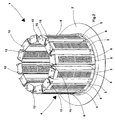
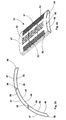
- FIG 1 shows, overall, a burner according to the invention, comprising a base element 2, with for example the shape of a flange, and a head element 3, with for example the shape of a bottom, between which a diffuser 4 is arranged and fixed consisting of a plurality of diffuser elements 5, arranged as a cylindrical envelope configuration.
- Each diffuser element 5 ( Figure 4 ) has a U-shaped cross section, with a first wall 7 of each diffuser element 5 that has a substantially rectangular shape and is turned towards the outside of the burner 1; on the wall 7 openings 6 are made for the passage of the mixture of air and fuel delivered inside the burner 1.
- the diffuser element 5 furthermore comprises two side walls 8 connected to the two greater opposite sides of the first wall 7 and placed in an approximately radial direction and two front walls 14, only one of which is visible in Figure 4 , connected to the lesser sides of the first wall 7 and approximately perpendicular thereto.
- a flow-distributing element 9 can be arranged, consisting, for example, of a plate 10 ( Figure 8 ), on which holes 11 are distributed for the passage of the mixture of air and fuel.
- the plate 10 is furthermore provided, on two sides that are opposite each other, with respective bumps 13, which act as spacers to keep the plate 10 at a distance from the wall 7.
- the flow-distributing elements 9 can be inserted inside the diffuser elements 5 by resting them against pairs of support rods 12.
- the holes 15 have shapes and dimensions such as to couple with play with the rods 12 in such a way that the latter do not hinder heat expansion of the diffuser element 5.
- the rods 12 also act as fixing means of the diffuser element 5 to the base element 2 and to the head element 3 of the burner 1.
- the diffuser elements 5 can be coupled with the base element 2 and with the head element 3 of the burner 1 by inserting the ends of the diffuser elements into suitable seats made in the base element 2 and in the head element 3, respectively.
- the dimensions of the seats are chosen in such a way as to enable coupling with play of the diffuser elements 5, in such a way as not to hinder heat expansion.
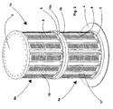
- FIG 3 shows a version la of the burner 1 shown in Figures 1 and 2 .
- This burner la is substantially obtained by connecting together a first burner body 17 that is substantially identical to the burner 1 and a second burner body 18 aligned on a straight axis.
- the first burner body 17 comprises a flange-shaped base element 2 and a head element 19, with a substantially annular shape, between which a first diffuser 4a is arranged and fixed consisting of a plurality of diffuser elements 5, arranged as a cylindrical envelope configuration.
- the second burner body 18 comprises a base element 19a, with a shape similar to the head element 19 of the first burner body 17 and connected to it, and a head element 3, with a substantially circular shape, between which a second diffuser 4b is arranged and fixed also consisting of a plurality of diffuser elements 5, arranged as a cylindrical envelope configuration.
- FIGS 5 , 6 , 7 show a further embodiment of a burner 20 according to the invention, consisting of a substantially rectangular frame 21 with a peripheral flange 22, which is also substantially rectangular, inside which a row of diffuser elements 5 is arranged that are alongside one another to form a diffuser 25 having a substantially flat surface.
- the support rods 12 transversely in relation to the diffuser elements 5, passing through holes 16 made in the side walls 8 of each diffuser element 5 and further holes made on pairs of opposite sides 24 of the frame 21.
- the rods 12, by passing through the different adjacent diffuser elements 5, and the pairs of opposite sides 24, also act as connecting elements connecting the diffuser elements 5 together and with the frame 21.
- the rods 12 are coupled with play with the holes 16 and with the further holes made on the opposite sides 24 in such a way as not to hinder heat expansion of the diffuser elements 5.
- the diffuser elements 5 can be provided inside the frame 21 seats that are suitable for receiving and holding in place opposite ends of the diffuser elements 5. Coupling between the diffuser elements 5 and the seats occurs with play in such a way that heat expansion of the diffuser elements 5 is not hindered.
- FIG 9 shows a yet further embodiment of a burner 25 according to the invention, similar to the burner 20 shown in Figures 5 , 6 , 7 , from which it differs only inasmuch as inside the substantially rectangular frame 21 a double row of diffuser elements 5 is arranged.
- the diffuser elements 5 of the two rows are arranged in such a way as to be able to expand in a substantially free manner due to the effect of the temperature variations to which they are subjected during burner operation 25.
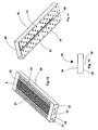
- FIGs 10 to 12 show a second embodiment of a diffuser element 26 of a burner according to the invention.
- This diffuser element 26 has a box-shaped body, which gives it great flexional rigidity.
- the diffuser element shown in Figures 10, 11 has a row of slits 6, bordered by two double rows of holes 27.
- a second face 29, opposite the first face 28 and intended to be turned towards the inside of the burner, is provided with a series of openings 31, for example in the shape of holes, distributed along the second face 29.
- This second face 29 acts as a distributor of the flow of mixture delivered into the burner.
- the diffuser element 26 is then integrated with a mixture-flow-distributing element, which enables considerable cost savings and saving of assembly time of the burner according to the invention.
- a central incision 30 may be made that extends along the entire length of the face, parallel to the greater sides thereof. This incision 30 is used to considerably reduce the value of the mechanical stress occurring on the diffuser element 26 due to the temperature variations to which it is subjected during burner operation. This is because the presence of the incision 30 enables the diffuser element 26 to expand in a substantially free manner in a perpendicular direction to the incision 30.
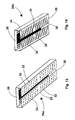
- Figures 13 and 14 show a third embodiment of a diffuser element 26a and a fourth embodiment of a diffuser element 26b according to the invention.
- the diffuser elements 26a are 26b are similar to the diffuser element 26 from which they differ by the shape of the openings made on the second face 29.
- the diffuser element 26a has on the second face 29 rows of openings consisting of slits 32 alternating with holes 33 whilst the diffuser element 26a has on the second face 29 rows of slits 34, staggered between themselves.
- Figures 15 and 16 show a fifth embodiment of a diffuser element 26c, similar to the diffuser element 26, from which it differs by the fact that at the ends of the first face 28 it has projections 35, turned towards the inside of the element 26. These projections 35 are used to make coupling of the diffuser elements 26c with the flange 2 and the bottom 3 of the burner quicker and easier.
- Figure 17 shows a version 26d of the diffuser element 26c that has projections 35a that are similar to the projections 35 but are turned towards the outside of the diffuser element 26d.
- FIG 18 shows a version 9a of the distributing element 9 shown in Figures 7 and 8 .
- the distributing element 9a differs from the distributing element 9 inasmuch as the bumps 13 are replaced by end protrusions 36 of the body 10, which also act as spacers.
- Figure 19 shows a sixth embodiment of a diffuser element 37 with a U-shaped cross section with a first face 38 intended to be turned towards the outside of the burner, and a second and third face 39, 40, that are substantially perpendicular to the first face 38 and are intended to be turned towards the inside of the burner.
- On the face 38 openings 41, 42 are made for the passage of the mixture of air and fuel.
- the openings 41, 42 may have the shape of slits 41 and of holes 42.
- the diffuser element 37 shown in Figure 19 is provided on the first face 38 with two rows of slits 41 that are parallel to each other between which a plurality of holes 42 is arranged.
- further slits 43 may be made that extend along the entire width of the zone of the face 38 on which the slits 41 and the holes 42 are located. These further slits 43, in addition to acting as openings for the passage of the mixture, enable the face 38 to absorb heat expansion without being subjected to excessive mechanical stress generated by such expansion.
- the diffuser element 37 is particularly suitable for making a burner with a substantially flat diffuser, like the ones shown in Figures 5 and 9 .
- Figure 20 shows a seventh embodiment of a diffuser element 44.
- This diffuser element 44 integrated with a flow-distributing element, has a similar shape to the diffuser elements shown in Figures 10 to 17 and on its first face 28 has the same opening distribution of the diffuser element 37, including the further slits 43.
- Figure 21 shows an enlarged view of a version 43a of the further slits 43, which have widenings 45 at the respective ends to reduce the risk of concentrations of mechanical stress due to the heat expansion that occurs during burner operation.
- FIGS 22, 22a, 23 show an eighth embodiment of a diffuser element 46 according to the invention.
- the diffuser element 46 has a box structure, with a first convex face 47 intended to be turned towards the outside of the burner and having the shape of a cylindrical surface sector and a second concave face 48 intended to be turned towards the inside of the burner and also having the shape of a cylindrical surface sector.
- the two faces 47 and 48 being joined by curved lengths 49, 50.
- openings 51, 52, 53 are made for the passage of the mixture of air and fuel.
- the openings 51, 52 may have the shape of slits 51 and of holes 52.
- the diffuser element 46 shown in Figures 22, 22a, 23 is provided on the first face 47 with two rows of slits 51 that are parallel to one another between which a plurality of holes 52 is arranged.
- further slits 53 can be arranged that extend along the entire width of the zone of the first face 47 on which the slits 51 and the holes 52 are located.
- a series of openings 54 is made, for example in the shape of holes, distributed along the second face 48.
- This second face 48 acts as a distributor of the flow of mixture delivered into the burner.
- the diffuser element 46 is then integrated with a mixture-flow-distributing element, which enables significant savings to be made both in terms of manufacturing costs and assembly time of the burner according to the invention.
- a central incision 55 can be made that extends along the entire length of the face, parallel to the greater sides thereof.
- This incision 55 significantly reduces the value of the mechanical stress that occurs on the diffuser element 46 because of the temperature variations to which it is subjected during burner operation. This is because the presence of the incision 55 enables the diffuser element 46 to expand in a substantially free manner in a direction that is perpendicular to the incision 55.
- projections 56 are made that make coupling of the diffuser elements 46 with the flange 2 and the bottom 3 of the burner 1 faster and easier.
- the projections 56 can be pointed to the outside of the diffuser element 46, or towards the inside thereof.
- Figures 24 and 25 show a ninth embodiment of a diffuser element 57 according to the invention similar to the diffuser element 46 shown in Figures 22, 22a, 23 .
- the diffuser element 57 differs from the diffuser element 46 inasmuch as the walls 58, 59 that connect the first face 47 and the second face 48 are shaped in such a way as to be shapingly coupled with the walls of adjacent diffuser elements 57.
- This type of coupling minimises the risk of spillage of mixture between the side walls of adjacent diffuser elements 57, thereby increasing the efficiency of the burner.
- Figures 26, 27 and 28 show a tenth embodiment of a diffuser element 60 according to the invention.
- the diffuser element 60 has a U-shaped cross section with a first face 61 intended to be turned towards the outside of the burner, and a second and third face 62, 63 that are substantially perpendicular to the first face 61 and are intended to be turned towards the inside of the burner.
- openings 51, 52, 53 are made that have a shape and distribution that are similar to the corresponding openings made on the first face 47 of the diffuser elements 46 and 57 disclosed above.
- the second and third face 62 and 63 are respectively joined at their free ends with a second distributing element 64 that also has a U-shaped cross section with a first face 65 substantially parallel to the first face 61 of the diffuser element 60 and a second and third face, respectively 66 and 67, substantially parallel to the second face 62 and to the third face 63, respectively of the diffuser element 60.
- openings 68 are made for the passage and the distribution of the flow of the mixture of air and fuel.
- a central incision 69 can be made, extending along the entire length of the face 65, parallel to the greater sides thereof.
- This incision 69 has functions that are completely similar to those of the incision 55 of the diffuser elements 46 and 57 disclosed previously.
- Figures 29, 30, 31 show an eleventh embodiment of a diffuser element 70, having a substantially open box shape, with a top face 71 intended to be turned towards the outside of the burner, two front faces 72, that are substantially perpendicular to the lesser sides of the top face 71 and two side faces 73, 74 that are substantially perpendicular to the greater sides of the top face 71.
- the side faces 73, 74 are shaped in such a way as to be shapingly coupled with the corresponding side faces of adjacent diffuser elements 70. This type of coupling minimises the risk of spillage of mixture between the walls of adjacent diffuser elements 70, thus increasing burner efficiency.
- openings 51, 52, 53 are made that have a shape and distribution similar to the corresponding openings already disclosed with reference to the diffuser elements 46, 57, 60.
- Figures 32 to 36 show a twelfth embodiment of a diffuser element 75 according to the invention.
- This diffuser element 75 has an open box shape similar to that of the diffuser element 70, with a top face 76 intended to be turned towards the outside of the burner, two front faces 77, 78, that are substantially perpendicular to the lesser sides of the top face 76 and two side faces 79, 80, that are substantially perpendicular to the greater sides of the top face 76.
- openings 81, 82, 83 are made for the evacuation of the mixture of air and fuel.
- the openings 81 have the shape of slits arranged in traverse rows staggered between themselves in a central zone of the top face 76; the openings 82 have the shape of holes arranged in traverse rows staggered between themselves, in two side zones of the top face 76.
- the openings 83 are traverse slits that extend along the entire width of the top face 76 and continue for a short length, at both their ends on the side walls 79 and 80.
- the slits 83 have widenings 84 at both their ends.
- the slits 83 In addition to acting as openings for the passage of the mixture, the slits 83 also enable the top face 76 to absorb heat expansion without being subjected to excessive mechanical stress generated by the heat expansion. Furthermore, the widenings 84 enable the risk of concentrations of mechanical stress caused by the heat expansion to be reduced, thereby increasing the resistance of the diffuser element 75 to the thermal stress that occurs during burner operation.
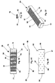
- a flow-distributing element 85 ( Figures 35, 36 ) can be arranged that for example comprises a plate 86 on which holes 87 are distributed for the passage of the mixture of air and fuel.
- the plate 86 is provided with end protrusions 88 having a spacer function for maintaining the flow-distributing element 85 distanced from the top face 76 of the diffuser element 75.
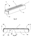
- Figures 37, 38 and 39 show a thirteenth embodiment of a diffuser element 89 according to the invention.
- This diffuser element 89 has a shape that is very similar to that of the diffuser element 75, shown in Figures 32, 33, 34 and differs therefrom only in terms of the shape and distribution of the openings 90, 91 made in the top face 76 for the evacuation of the mixture of air and fuel with which the burner is supplied.
- openings 90, 91 have the shape of slits and are distributed on staggered traverse rows that are located alternately on the entire width of the top face 76 of the diffuser element 89.
- the end slits 91 of the rows of slits that are located on the entire width of the top face 76 continue for a short length on the side faces 79 and 80 and terminate on the faces with a widening 92.
- the function of the end slits 91 and of the widening 92 is very similar to the function of the slits 83 with the respective widenings 84, disclosed with reference to the diffuser element 75 shown in Figures 32, 33, 34 .
- a flow-distributing element 85 ( Figures 40 and 41 ) can be arranged inside each diffuser element 89 .
- Figures 42 and 43 show a fourteenth embodiment of a diffuser element 93 according to the invention.
- the diffuser element 93 has a shape that is very similar to that of the diffuser elements 75 and 89 disclosed previously.
- openings 94, 95, 96 are made for the passage of the mixture of air and fuel.
- the openings 94 have the shape of slits, distributed on two traverse rows that are parallel to each other, between which a plurality of rows of holes 95 is arranged.
- further slits 96 are arranged that extend along the entire width of the top face 76 and continue for a short length at the respective ends on the side faces 79 and 80.
- the ends of each further slit 96 have a widening 97.
- Figures 44 and 45 disclose a fifteenth embodiment of a diffuser element 98 according to the invention, similar to the diffuser element 93 shown in Figures 42 and 43 .
- the further slits 96 terminate at their respective ends, on the side walls 79 and 80, with a length of L-shaped slit 99 that in turn terminates with a widening 100.
- this length of slit 99 and of the respective widening 100 is to further reduce the risk of concentrations of mechanical stress, which could be generated by the heat expansion to which the diffuser element 98 is subjected during burner operation.
- Figures 46 to 49 show assembly of a diffuser element 46 in a burner with a cylindrical envelope diffuser as for example shown in Figure 1 .
- the base element 2 and the head element 3 of the burner are respectively equipped with annular internally hollow protrusions 101, 102 with U-shaped sections, in which the ends of the diffuser elements 46 can be inserted.
- the front walls, 103 and 104 respectively, of the annular protrusions 101 and 102 are provided at regular intervals with projections 105 suitable for coupling with the projections 56 made in the ends of the diffuser elements 46 to fix in position each diffuser element 46 and prevent it from being able to undergo shifts during burner operation.
- projections 105 suitable for coupling with the projections 56 made in the ends of the diffuser elements 46 to fix in position each diffuser element 46 and prevent it from being able to undergo shifts during burner operation.
- the presence of projections 105 that are coupleable with the projections 56 of the diffuser element 46 makes the assembly of the burner diffuser very quick and easy.
- Figures 50 and 51 show a sixteenth embodiment of a diffuser element 106 according to the invention having a substantially triangular plan shape with a top face 107 in which openings 108, 108a are made for the evacuation of the mixture of air and fuel, side walls 109 and front wall 110.
- the openings 108, 108a may have the shape of rows of slits 108 alternating with rows of holes 108a.
- Figure 51 shows two diffuser elements 106, brought up to form a portion of burner diffuser.
- Figure 52 shows a burner 111 the diffuser of which is made with the diffuser elements 106 shown in Figures 50 and 51 .
- the burner 111 is provided with a cylindrical body 112, one of the bases of which forms a diffuser 113 made with the diffuser elements 106.
- the burner is provided with a tube 114 for conveying the mixture of air and fuel to the burner body 112.
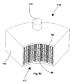
- Figure 53 shows a portion of a burner 115, the body 116 of which has a hollow cylindrical shape, the internal surface of which forms the diffuser 117 of the burner, made with diffuser elements according to the invention, for example diffuser elements 60 according to the tenth embodiment of the diffuser elements.
- Figure 54 shows a cylindrical burner 118 according to the invention, similar to the burner shown in Figure 1 , wherein the diffuser 119 is made with a plurality of diffuser elements according to the invention, for example diffuser elements 46, 57, or 60 according to the eighth, ninth and tenth embodiments respectively.
- Figures 55 and 56 show a first version of the diffuser element 5 shown in Figure 4 .
- the diffuser element 5 is provided on its front faces 14 with respective tabs 120 obtained by punching the front faces 14.
- the tabs 120 are used to secure and hold in position a distributing element 85 inserted in the diffuser element 5.
- the tabs 120 are bent towards the inside of the diffuser element 5 in such a way as to interfere with the distributing element 85 in such a way as to secure it and keep it in position as shown in Figure 56 .
- Figures 57 and 58 show a second version of the diffuser element 5 shown in Figure 4 .
- the diffuser element 5 is provided with respective recesses 121 on its front faces 14.
- the recesses 121 are used to secure and hold in position a distributing element 85a inserted in the diffuser element 5.
- the flow-distributing element 85a is similar to the flow-distributing element 85 and differs from it by the presence on the plate 86a of a plurality of traverse projections 122, that are substantially parallel to one another, the function of which is to act as spacers, to keep the flow-distributing element 85a at a distance from the top face 7 of the diffuser element 5.
- the recesses 121 of the front faces 14 secure and maintain in position the distributing element 85a, as shown in Figure 58 .
- Figures 59 and 60 show a system of fitting of a diffuser element 5 in a burner 20 like the one shown in Figure 5 .
- the walls 24 of the substantially rectangular frame 21 of the burner 20, parallel to the front faces 14 of the diffuser element 5, are provided with recesses 123 positioned in such a way as to keep the diffuser element 5 in position after the latter has been placed in position in the substantially rectangular frame 21, as shown in Figure 60 .
Landscapes
- Engineering & Computer Science (AREA)
- Chemical & Material Sciences (AREA)
- Combustion & Propulsion (AREA)
- Mechanical Engineering (AREA)
- General Engineering & Computer Science (AREA)
- Gas Burners (AREA)
- Pressure-Spray And Ultrasonic-Wave- Spray Burners (AREA)
Abstract
Description
- The present invention relates to a burner, in particular to a premixed burner with a diffuser resistant to high temperatures.
- In burners subject to high operating temperatures, such as for example premixed burners, the high thermal stress may easily cause very great mechanical deformations and stress to the burner diffuser, which may lead to the breaking of the diffuser. This drawback occurs with any form of burner diffuser, but has been found to be particularly serious in burners with flat diffusers. To overcome this drawback, it has been proposed to use special materials to make the burner diffuser, for example a metal mesh, or a ceramic material. However, this leads to a significant increase in the cost of the burner if the metal mesh is used and significant fragility of the diffuser if a ceramic material is used.
-
EP0774623 describes a burner for use in a gas-fired burner device, comprising a housing at least partly covered by a burner deck provided with outflow openings for allowing, during use, the passage of a gas or gas/air mixture from the inside of the housing to the environment, with the circumferential edges of the burner deck being retained so as to be movable relative to the housing, wherein the burner deck comprises a series of burner deck parts arranged next to each other, which burner deck parts each comprise a row of outflow openings in communication with the inside of the housing, while between burner deck parts arranged next to each other bridges are included which are fixedly connected with the housing, in which bridges the proximal edges of the burner deck parts connecting thereto are movably retained, the arrangement being such that during use each burner deck part can deform at least in the plane of the burner deck part in question, independently of the other burner deck parts the housing and the bridges. -
EP0679838 describes a gas burner that consists of a distribution chamber to receive air and a combustible gas, partially delimited by a thin perforated panel which acts as a burner bar. The distribution chamber has an upper end with a series of feed apertures facing the perforated panel, while the perforated zones of the latter are not situated directly in line with some of the apertures. The offset perforated sections are curved, with convex sides facing towards the distribution chamber and located between its feed apertures. Apart from the curved sections, the perforated panel is generally flat, and the gas feed apertures in the distribution chamber, which are set in a plane parallel to the perforated panel, are connected to feed ducts in the form of Venturi tubes fed by individual nozzles. -
JP58035314 outer combustion wall 13. Besides agass feeder body 25, which is provided withgas injecting ports 30 is fitted to the lower part of a boxtype combustion section 15 by the intermediary of projectingparts 31. With such an arrangement, a flat type combustor with radiation obtained from one side, is composed so as to make the best use of its characteristics as a full secondary air combustor, and it can be installed in places in various circumstances. One object of the present invention is to provide a burner suitable for operating at high operating temperatures that is highly resistant to thermal stress without special materials being required to make the diffuser, which is simple and relatively cheap to build. According to the invention, a burner is provided that is suppliable with a mixture of air and fuel, comprising a burner body provided with a diffuser in which openings are made for the passage and subsequent combustion of the mixture. The diffuser is divided into a plurality of diffuser elements that are adjacent to one another, each element being at least partially free to expand in at least one direction. Each diffuser element is associated with a flow-distributing element and is provided with openings for the passage of said mixture. The invention is characterised in that each flow-distributing element is arranged inside a diffuser element. - The diffuser divided into a plurality of elements adjacent to one another, partially free to expand in at least one direction, has resistance to thermal stress that is significantly greater than is the case with a monobloc diffuser inasmuch as the heat expansions that occurs during burner operation on each diffuser element, induced by said temperature variations, is noticeably reduced, with a consequent noticeable reduction of deformation and of the mechanical stress induced by it.
- According to a preferred embodiment of the present invention, each diffuser element has a shape that is such as to give it great mechanical rigidity.
- This enables the flexional stability of each diffuser element to be improved, further increasing resistance to thermal stress.
- According to a further aspect of the present invention rigidity-varying means is provided that is suitable for diminishing the rigidity of the diffuser element in a direction parallel to its greater dimension.
- This enables mechanical stresses due to heat expansion in the direction of the greater dimension to be further diminished.
- The invention will now be disclosed by way of non-limiting examples by reference to the attached drawings in which:
-
Figure 1 is a perspective view of a burner according to the invention, with a diffuser having the shape of a cylindrical envelope; -
Figure 2 is a view of the partially dismantled burner inFigure 1 ; -
Figure 3 is a view of a further burner according to the invention with a double diffuser having the shape of a cylindrical envelope; -
Figure 4 is a perspective view of a first embodiment of a diffuser element according to the invention; -
Figure 5 is a perspective view of a burner with a diffuser having a substantially flat shape; -
Figure 6 is a perspective view of the diffuser elements of the burner inFigure 5 ; -
Figure 7 is an enlarged and fragmentary detail ofFigure 6 , in which a flow-distributing element is shown that is fitted inside each diffuser element to make uniform the distribution of the flow of mixture to the openings of the diffuser element; -
Figure 8 is a perspective view of the distributing element shown inFigure 7 ; -
Figure 9 is a perspective view of a further burner with a diffuser having a substantially flat shape; -
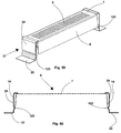
Figures 10 and 11 are perspective views of a second embodiment of a diffuser element of the burner according to the invention, integrated with a flow-distributing element; -
Figure 12 is a cross section of the diffuser element ofFigures 10 and 11 ; -
Figures 13 and 14 are perspective views of a third and of a fourth embodiment of a diffuser element of the burner according to the invention, integrated with a flow-distributing element; -
Figure 15 is a perspective view of a fifth embodiment of a diffuser element of the burner according to the invention; -
Figure 16 is a cross section of the diffuser element inFigure 15 ; -
Figure 17 is a section like the one inFigure 16 , relating moreover to a modification to the diffuser inFigure 15 ; -
Figure 18 is a perspective view of a version of the distributing element shown inFigures 7 and8 ; -
Figure 19 is a perspective view of a sixth embodiment of a diffuser element of a burner according to the invention; -
Figure 20 is a perspective view of a seventh embodiment of a diffuser element according to the invention, integrated with a flow-distributing element; -
Figure 21 is an enlarged view of a detail of the diffuser elements ofFigures 19 and 20 ; -
Figure 22 is a perspective view of an eighth embodiment of a diffuser element according to the invention; -
Figure 22a is a perspective view from below of the diffuser element inFigure 22 ; -
Figure 23 is a cross section of the diffuser element inFigure 4 ; -
Figure 24 is a perspective view of a ninth embodiment of a diffuser element according to the invention; -
Figure 25 is a section view of three diffuser elements like the one inFigure 24 , brought up to form a diffuser like the burner diffuser inFigure 1 ; -
Figure 26 is a view from above of a tenth embodiment of a diffuser element according to the invention; -
Figure 27 is a view from below of the diffuser element inFigure 26 ; -
Figure 28 is a cross section of the diffuser element inFigure 26 ; -
Figure 29 is a perspective view of an eleventh embodiment of a diffuser element for a burner according to the invention; -
Figure 30 is a perspective view of two diffuser elements like the one inFigure 29 , brought up to form the diffuser of a burner according to the invention; -
Figure 31 is a front view of the two diffuser elements inFigure 30 ; -
Figure 32 is a perspective view of a twelfth embodiment of a diffuser element according to the invention; -
Figure 33 is a view from above of the diffuser element inFigure 32 ; -
Figure 34 is an enlarged detail of the diffuser element inFigure 32 ; -
Figure 35 is a plan view of a flow-distributing element that is associatable with a diffuser element like the one inFigure 32 ; -
Figure 36 is a side view of the flow-distributing element inFigure 35 ; -
Figure 37 is a perspective view of a thirteenth embodiment of a diffuser element according to the invention; -
Figure 38 is a view from above of the diffuser element inFigure 37 ; -
Figure 39 is an enlarged detail of the diffuser element inFigure 37 ; -
Figure 40 is a plan view of a flow-distributing element that is associatable with a diffuser element like the one inFigure 37 ; -
Figure 41 is a side view of the flow-distributing element inFigure 40 ; -
Figure 42 is a perspective view of a fourteenth embodiment of a diffuser element according to the invention; -
Figure 43 is an enlarged detail ofFigure 42 ; -
Figure 44 is a perspective view of a fifteenth embodiment of a diffuser element according to the invention; -
Figure 45 is an enlarged detail ofFigure 44 ; -
Figures 46, 47, 48 and 49 are schematic views that show the fitting of a diffuser element according to the invention, for example of the type shown inFigures 22, 22a and 23 , to make the diffuser of a burner of the type shown inFigure 1 . -
Figures 50 and 51 are perspective views of a sixteenth embodiment of a diffuser element according to the invention; -
Figure 52 is a perspective view of a burner made with the diffuser elements shown inFigures 50 and 51 . -
Figure 53 is a fragmentary perspective view of a portion of a burner with a concave cylindrical diffuser made with diffuser elements according to the invention; -
Figure 54 is a perspective view of a burner with a convex cylindrical diffuser, made with diffuser elements according to the invention; -
Figure 55 is a perspective view of a first version of a diffuser element like the one inFigure 4 ; -
Figure 56 is a longitudinal section of the diffuser element inFigure 55 ; -
Figure 57 is a perspective view of a second version of a diffuser element like the one inFigure 4 ; -
Figure 58 is a longitudinal section of the diffuser element inFigure 57 ; -
Figure 59 is a perspective view of a fitting system of a diffuser element like the one inFigure 4 in a burner like the one shown inFigure 5 ; -
Figure 60 is a longitudinal section ofFigure 59 . - In
Figure 1, 1 shows, overall, a burner according to the invention, comprising abase element 2, with for example the shape of a flange, and ahead element 3, with for example the shape of a bottom, between which a diffuser 4 is arranged and fixed consisting of a plurality ofdiffuser elements 5, arranged as a cylindrical envelope configuration. Each diffuser element 5 (Figure 4 ) has a U-shaped cross section, with afirst wall 7 of eachdiffuser element 5 that has a substantially rectangular shape and is turned towards the outside of theburner 1; on thewall 7openings 6 are made for the passage of the mixture of air and fuel delivered inside theburner 1. Thediffuser element 5 furthermore comprises twoside walls 8 connected to the two greater opposite sides of thefirst wall 7 and placed in an approximately radial direction and twofront walls 14, only one of which is visible inFigure 4 , connected to the lesser sides of thefirst wall 7 and approximately perpendicular thereto. Inside each diffuser element 5 a flow-distributingelement 9 can be arranged, consisting, for example, of a plate 10 (Figure 8 ), on which holes 11 are distributed for the passage of the mixture of air and fuel. Theplate 10 is furthermore provided, on two sides that are opposite each other, withrespective bumps 13, which act as spacers to keep theplate 10 at a distance from thewall 7. The flow-distributingelements 9 can be inserted inside thediffuser elements 5 by resting them against pairs ofsupport rods 12. Thesesupport rods 12, in the case of the burner inFigures 1 and2 , are arranged substantially parallel to thewalls 8 of therespective diffuser element 5 and protrude by their ends throughholes 15 made in thefront walls 14. Theholes 15 have shapes and dimensions such as to couple with play with therods 12 in such a way that the latter do not hinder heat expansion of thediffuser element 5. Therods 12 also act as fixing means of thediffuser element 5 to thebase element 2 and to thehead element 3 of theburner 1. Alternatively, thediffuser elements 5 can be coupled with thebase element 2 and with thehead element 3 of theburner 1 by inserting the ends of the diffuser elements into suitable seats made in thebase element 2 and in thehead element 3, respectively. The dimensions of the seats are chosen in such a way as to enable coupling with play of thediffuser elements 5, in such a way as not to hinder heat expansion. -
Figure 3 shows a version la of theburner 1 shown inFigures 1 and2 . This burner la is substantially obtained by connecting together afirst burner body 17 that is substantially identical to theburner 1 and asecond burner body 18 aligned on a straight axis. Thefirst burner body 17 comprises a flange-shapedbase element 2 and ahead element 19, with a substantially annular shape, between which afirst diffuser 4a is arranged and fixed consisting of a plurality ofdiffuser elements 5, arranged as a cylindrical envelope configuration. Thesecond burner body 18 comprises abase element 19a, with a shape similar to thehead element 19 of thefirst burner body 17 and connected to it, and ahead element 3, with a substantially circular shape, between which asecond diffuser 4b is arranged and fixed also consisting of a plurality ofdiffuser elements 5, arranged as a cylindrical envelope configuration. -
Figures 5 ,6 ,7 show a further embodiment of aburner 20 according to the invention, consisting of a substantiallyrectangular frame 21 with aperipheral flange 22, which is also substantially rectangular, inside which a row ofdiffuser elements 5 is arranged that are alongside one another to form adiffuser 25 having a substantially flat surface. - In this
burner 20 it is advantageous to arrange thesupport rods 12 transversely in relation to thediffuser elements 5, passing throughholes 16 made in theside walls 8 of eachdiffuser element 5 and further holes made on pairs ofopposite sides 24 of theframe 21. In this way therods 12, by passing through the differentadjacent diffuser elements 5, and the pairs ofopposite sides 24, also act as connecting elements connecting thediffuser elements 5 together and with theframe 21. - The
rods 12 are coupled with play with theholes 16 and with the further holes made on theopposite sides 24 in such a way as not to hinder heat expansion of thediffuser elements 5. - Alternatively, to couple the
diffuser elements 5 with theframe 21, inside theframe 21 seats can be provided that are suitable for receiving and holding in place opposite ends of thediffuser elements 5. Coupling between thediffuser elements 5 and the seats occurs with play in such a way that heat expansion of thediffuser elements 5 is not hindered. -
Figure 9 shows a yet further embodiment of aburner 25 according to the invention, similar to theburner 20 shown inFigures 5 ,6 ,7 , from which it differs only inasmuch as inside the substantially rectangular frame 21 a double row ofdiffuser elements 5 is arranged. Thediffuser elements 5 of the two rows are arranged in such a way as to be able to expand in a substantially free manner due to the effect of the temperature variations to which they are subjected duringburner operation 25. -
Figures 10 to 12 show a second embodiment of adiffuser element 26 of a burner according to the invention. Thisdiffuser element 26 has a box-shaped body, which gives it great flexional rigidity. Afirst face 28 of the body of thediffuser element 26, intended to be turned towards the outside of the burner, acts as a diffuser and is provided with a plurality ofopenings openings slits 6 and/or ofholes 27. The diffuser element shown inFigures 10, 11 has a row ofslits 6, bordered by two double rows ofholes 27. Asecond face 29, opposite thefirst face 28 and intended to be turned towards the inside of the burner, is provided with a series ofopenings 31, for example in the shape of holes, distributed along thesecond face 29. Thissecond face 29 acts as a distributor of the flow of mixture delivered into the burner. - The
diffuser element 26 is then integrated with a mixture-flow-distributing element, which enables considerable cost savings and saving of assembly time of the burner according to the invention. - In the second face 29 a
central incision 30 may be made that extends along the entire length of the face, parallel to the greater sides thereof. Thisincision 30 is used to considerably reduce the value of the mechanical stress occurring on thediffuser element 26 due to the temperature variations to which it is subjected during burner operation. This is because the presence of theincision 30 enables thediffuser element 26 to expand in a substantially free manner in a perpendicular direction to theincision 30. -
Figures 13 and 14 show a third embodiment of adiffuser element 26a and a fourth embodiment of adiffuser element 26b according to the invention. Thediffuser elements 26a are 26b are similar to thediffuser element 26 from which they differ by the shape of the openings made on thesecond face 29. - The
diffuser element 26a has on thesecond face 29 rows of openings consisting ofslits 32 alternating withholes 33 whilst thediffuser element 26a has on thesecond face 29 rows ofslits 34, staggered between themselves. -
Figures 15 and 16 show a fifth embodiment of adiffuser element 26c, similar to thediffuser element 26, from which it differs by the fact that at the ends of thefirst face 28 it hasprojections 35, turned towards the inside of theelement 26. Theseprojections 35 are used to make coupling of thediffuser elements 26c with theflange 2 and thebottom 3 of the burner quicker and easier. -
Figure 17 shows aversion 26d of thediffuser element 26c that hasprojections 35a that are similar to theprojections 35 but are turned towards the outside of thediffuser element 26d. -
Figure 18 shows a version 9a of the distributingelement 9 shown inFigures 7 and8 . The distributing element 9a differs from the distributingelement 9 inasmuch as thebumps 13 are replaced byend protrusions 36 of thebody 10, which also act as spacers. -
Figure 19 shows a sixth embodiment of adiffuser element 37 with a U-shaped cross section with afirst face 38 intended to be turned towards the outside of the burner, and a second andthird face first face 38 and are intended to be turned towards the inside of the burner. On theface 38openings openings slits 41 and ofholes 42. Thediffuser element 37 shown inFigure 19 is provided on thefirst face 38 with two rows ofslits 41 that are parallel to each other between which a plurality ofholes 42 is arranged. At regular intervals along the rows ofslits 41 and holes 42further slits 43 may be made that extend along the entire width of the zone of theface 38 on which theslits 41 and theholes 42 are located. These further slits 43, in addition to acting as openings for the passage of the mixture, enable theface 38 to absorb heat expansion without being subjected to excessive mechanical stress generated by such expansion. - The
diffuser element 37 is particularly suitable for making a burner with a substantially flat diffuser, like the ones shown inFigures 5 and9 . -
Figure 20 shows a seventh embodiment of adiffuser element 44. Thisdiffuser element 44, integrated with a flow-distributing element, has a similar shape to the diffuser elements shown inFigures 10 to 17 and on itsfirst face 28 has the same opening distribution of thediffuser element 37, including the further slits 43. - Lastly,
Figure 21 shows an enlarged view of aversion 43a of thefurther slits 43, which havewidenings 45 at the respective ends to reduce the risk of concentrations of mechanical stress due to the heat expansion that occurs during burner operation. -
Figures 22, 22a, 23 show an eighth embodiment of adiffuser element 46 according to the invention. Thediffuser element 46 has a box structure, with a firstconvex face 47 intended to be turned towards the outside of the burner and having the shape of a cylindrical surface sector and a secondconcave face 48 intended to be turned towards the inside of the burner and also having the shape of a cylindrical surface sector. The two faces 47 and 48 being joined bycurved lengths - On said
first face 47openings openings slits 51 and ofholes 52. Thediffuser element 46 shown inFigures 22, 22a, 23 is provided on thefirst face 47 with two rows ofslits 51 that are parallel to one another between which a plurality ofholes 52 is arranged. At regular intervals, along the rows ofslits 51 and holes 52, further slits 53 can be arranged that extend along the entire width of the zone of thefirst face 47 on which theslits 51 and theholes 52 are located. These further slits 53, in addition to acting as openings for the passage of the mixture, enable thefirst face 47 to absorb heat expansion without being subjected to excessive mechanical stress generated by the expansion. - On the second face 48 a series of
openings 54 is made, for example in the shape of holes, distributed along thesecond face 48. Thissecond face 48 acts as a distributor of the flow of mixture delivered into the burner. - The
diffuser element 46 is then integrated with a mixture-flow-distributing element, which enables significant savings to be made both in terms of manufacturing costs and assembly time of the burner according to the invention. - In the second face 48 a
central incision 55 can be made that extends along the entire length of the face, parallel to the greater sides thereof. Thisincision 55 significantly reduces the value of the mechanical stress that occurs on thediffuser element 46 because of the temperature variations to which it is subjected during burner operation. This is because the presence of theincision 55 enables thediffuser element 46 to expand in a substantially free manner in a direction that is perpendicular to theincision 55. Near the ends of thefirst face 47projections 56 are made that make coupling of thediffuser elements 46 with theflange 2 and thebottom 3 of theburner 1 faster and easier. Theprojections 56 can be pointed to the outside of thediffuser element 46, or towards the inside thereof. -
Figures 24 and 25 show a ninth embodiment of adiffuser element 57 according to the invention similar to thediffuser element 46 shown inFigures 22, 22a, 23 . - The
diffuser element 57 differs from thediffuser element 46 inasmuch as thewalls first face 47 and thesecond face 48 are shaped in such a way as to be shapingly coupled with the walls ofadjacent diffuser elements 57. - This type of coupling minimises the risk of spillage of mixture between the side walls of
adjacent diffuser elements 57, thereby increasing the efficiency of the burner. -
Figures 26, 27 and 28 show a tenth embodiment of adiffuser element 60 according to the invention. - The
diffuser element 60 has a U-shaped cross section with afirst face 61 intended to be turned towards the outside of the burner, and a second andthird face first face 61 and are intended to be turned towards the inside of the burner. On thefirst face 61openings first face 47 of thediffuser elements - The second and
third face element 64 that also has a U-shaped cross section with afirst face 65 substantially parallel to thefirst face 61 of thediffuser element 60 and a second and third face, respectively 66 and 67, substantially parallel to thesecond face 62 and to thethird face 63, respectively of thediffuser element 60. - On the
first face 65 of the distributingelement 64openings 68 are made for the passage and the distribution of the flow of the mixture of air and fuel. - In the
first face 65 of the distributing element 64 acentral incision 69 can be made, extending along the entire length of theface 65, parallel to the greater sides thereof. Thisincision 69 has functions that are completely similar to those of theincision 55 of thediffuser elements -
Figures 29, 30, 31 show an eleventh embodiment of adiffuser element 70, having a substantially open box shape, with atop face 71 intended to be turned towards the outside of the burner, two front faces 72, that are substantially perpendicular to the lesser sides of thetop face 71 and two side faces 73, 74 that are substantially perpendicular to the greater sides of thetop face 71. - The side faces 73, 74 are shaped in such a way as to be shapingly coupled with the corresponding side faces of
adjacent diffuser elements 70. This type of coupling minimises the risk of spillage of mixture between the walls ofadjacent diffuser elements 70, thus increasing burner efficiency. - On the
top face 71 of thediffuser element 70openings diffuser elements -
Figures 32 to 36 show a twelfth embodiment of adiffuser element 75 according to the invention. - This
diffuser element 75 has an open box shape similar to that of thediffuser element 70, with atop face 76 intended to be turned towards the outside of the burner, two front faces 77, 78, that are substantially perpendicular to the lesser sides of thetop face 76 and two side faces 79, 80, that are substantially perpendicular to the greater sides of thetop face 76. - On the
top face 76openings - The
openings 81 have the shape of slits arranged in traverse rows staggered between themselves in a central zone of thetop face 76; theopenings 82 have the shape of holes arranged in traverse rows staggered between themselves, in two side zones of thetop face 76. Theopenings 83 are traverse slits that extend along the entire width of thetop face 76 and continue for a short length, at both their ends on theside walls slits 83 havewidenings 84 at both their ends. - In addition to acting as openings for the passage of the mixture, the
slits 83 also enable thetop face 76 to absorb heat expansion without being subjected to excessive mechanical stress generated by the heat expansion. Furthermore, thewidenings 84 enable the risk of concentrations of mechanical stress caused by the heat expansion to be reduced, thereby increasing the resistance of thediffuser element 75 to the thermal stress that occurs during burner operation. - Inside each diffuser element 75 a flow-distributing element 85 (
Figures 35, 36 ) can be arranged that for example comprises aplate 86 on which holes 87 are distributed for the passage of the mixture of air and fuel. Theplate 86 is provided withend protrusions 88 having a spacer function for maintaining the flow-distributingelement 85 distanced from thetop face 76 of thediffuser element 75. -
Figures 37, 38 and 39 show a thirteenth embodiment of adiffuser element 89 according to the invention. - This
diffuser element 89 has a shape that is very similar to that of thediffuser element 75, shown inFigures 32, 33, 34 and differs therefrom only in terms of the shape and distribution of theopenings top face 76 for the evacuation of the mixture of air and fuel with which the burner is supplied. - These
openings top face 76 of thediffuser element 89. - The end slits 91 of the rows of slits that are located on the entire width of the
top face 76 continue for a short length on the side faces 79 and 80 and terminate on the faces with a widening 92. - The function of the end slits 91 and of the widening 92 is very similar to the function of the
slits 83 with therespective widenings 84, disclosed with reference to thediffuser element 75 shown inFigures 32, 33, 34 . - Inside each diffuser element 89 a flow-distributing element 85 (
Figures 40 and 41 ) can be arranged. -
Figures 42 and 43 show a fourteenth embodiment of adiffuser element 93 according to the invention. - The
diffuser element 93 has a shape that is very similar to that of thediffuser elements - On the
top face 76 of thediffuser element 93openings openings 94 have the shape of slits, distributed on two traverse rows that are parallel to each other, between which a plurality of rows ofholes 95 is arranged. At regular intervals along the rows ofslits 94 and ofholes 95further slits 96 are arranged that extend along the entire width of thetop face 76 and continue for a short length at the respective ends on the side faces 79 and 80. The ends of each further slit 96 have a widening 97. - The function of the
further slits 96 and of therespective end widenings 97 is the same as that of theslits 83 with therespective widenings 84 disclosed previously. -
Figures 44 and 45 disclose a fifteenth embodiment of adiffuser element 98 according to the invention, similar to thediffuser element 93 shown inFigures 42 and 43 . - In the
diffuser element 98, the further slits 96 terminate at their respective ends, on theside walls slit 99 that in turn terminates with a widening 100. - The function of this length of
slit 99 and of the respective widening 100 is to further reduce the risk of concentrations of mechanical stress, which could be generated by the heat expansion to which thediffuser element 98 is subjected during burner operation. -
Figures 46 to 49 show assembly of adiffuser element 46 in a burner with a cylindrical envelope diffuser as for example shown inFigure 1 . - The
base element 2 and thehead element 3 of the burner are respectively equipped with annular internallyhollow protrusions diffuser elements 46 can be inserted. - The front walls, 103 and 104 respectively, of the
annular protrusions projections 105 suitable for coupling with theprojections 56 made in the ends of thediffuser elements 46 to fix in position eachdiffuser element 46 and prevent it from being able to undergo shifts during burner operation. The presence ofprojections 105 that are coupleable with theprojections 56 of thediffuser element 46 makes the assembly of the burner diffuser very quick and easy. -
Figures 50 and 51 show a sixteenth embodiment of adiffuser element 106 according to the invention having a substantially triangular plan shape with atop face 107 in whichopenings side walls 109 andfront wall 110. - The
openings slits 108 alternating with rows ofholes 108a. -
Figure 51 shows twodiffuser elements 106, brought up to form a portion of burner diffuser. -
Figure 52 shows aburner 111 the diffuser of which is made with thediffuser elements 106 shown inFigures 50 and 51 . - The
burner 111 is provided with acylindrical body 112, one of the bases of which forms adiffuser 113 made with thediffuser elements 106. The burner is provided with atube 114 for conveying the mixture of air and fuel to theburner body 112. -
Figure 53 shows a portion of aburner 115, thebody 116 of which has a hollow cylindrical shape, the internal surface of which forms thediffuser 117 of the burner, made with diffuser elements according to the invention, forexample diffuser elements 60 according to the tenth embodiment of the diffuser elements. -
Figure 54 shows acylindrical burner 118 according to the invention, similar to the burner shown inFigure 1 , wherein thediffuser 119 is made with a plurality of diffuser elements according to the invention, forexample diffuser elements -
Figures 55 and 56 show a first version of thediffuser element 5 shown inFigure 4 . In this first version, thediffuser element 5 is provided on its front faces 14 withrespective tabs 120 obtained by punching the front faces 14. - The
tabs 120 are used to secure and hold in position a distributingelement 85 inserted in thediffuser element 5. - After insertion and positioning of the distributing
element 85 in thediffuser element 5, thetabs 120 are bent towards the inside of thediffuser element 5 in such a way as to interfere with the distributingelement 85 in such a way as to secure it and keep it in position as shown inFigure 56 . -
Figures 57 and 58 show a second version of thediffuser element 5 shown inFigure 4 . In this second version, thediffuser element 5 is provided withrespective recesses 121 on its front faces 14. - The
recesses 121 are used to secure and hold in position a distributingelement 85a inserted in thediffuser element 5. The flow-distributingelement 85a is similar to the flow-distributingelement 85 and differs from it by the presence on theplate 86a of a plurality oftraverse projections 122, that are substantially parallel to one another, the function of which is to act as spacers, to keep the flow-distributingelement 85a at a distance from thetop face 7 of thediffuser element 5. After inserting and positioning the distributingelement 85a in thediffuser element 5, therecesses 121 of the front faces 14 secure and maintain in position the distributingelement 85a, as shown inFigure 58 . -
Figures 59 and 60 show a system of fitting of adiffuser element 5 in aburner 20 like the one shown inFigure 5 . - In this fitting system, the
walls 24 of the substantiallyrectangular frame 21 of theburner 20, parallel to the front faces 14 of thediffuser element 5, are provided withrecesses 123 positioned in such a way as to keep thediffuser element 5 in position after the latter has been placed in position in the substantiallyrectangular frame 21, as shown inFigure 60 . - In the practical embodiment, the materials, dimensions and construction details used may be different from those indicated but be technically equivalent to them without thereby falling outside the legal scope of the present invention.
Claims (51)
- Burner (1; 1a; 20; 25; 111; 115; 118) suppliable with a mixture of air and fuel, comprising a burner body provided with a diffuser (4; 4a, 4b; 23; 113; 117; 119) in which openings are made for the passage and subsequent combustion of said mixture, said diffuser (4; 4a, 4b; 23; 113; 117; 119) being divided into a plurality of diffuser elements (5; 26; 26a; 26b; 26c; 26d; 37; 44; 46; 57; 60; 70; 75; 89; 93; 98; 106) that are adjacent to one another, each diffuser element (5; 26; 26a; 26b; 26c; 26d; 37; 44; 46; 57; 60; 70; 75; 89; 93; 98; 106) being at least partially free to expand in at least one direction, each diffuser element (5; 75; 89; 93; 98) being associated with a flow-distributing element (9; 9a; 64; 85; 85a) of said mixture and provided with openings (11; 68; 87) for the passage of said mixture, characterised in that each flow-distributing element (9; 9a; 64; 85; 85a) is arranged inside a diffuser element (5; 75; 89; 93; 98).
- Burner (1; 1a; 20; 25; 111; 115; 118) according to claim 1, characterised in that each diffuser element (5; 26; 26a; 26b; 26c; 26d; 37; 44; 46; 57; 60; 70; 75; 89; 93; 98; 106) has a shape that is such as to give it great mechanical rigidity.
- Burner (1; 1a; 20; 25; 115; 118) according to claim 1 or 2, wherein said diffuser element (5; 37; 60; 75; 89; 93) has a U-shaped cross section.
- Burner (1; 1a; 20; 25; 115; 118) according to claim 3, wherein said diffuser element (5; 37; 60; 70; 75; 89; 93) comprises a first face (7; 38; 61; 71; 76) having a substantially rectangular shape whereupon said openings (6; 41, 42; 51, 52; 81, 82; 90, 91; 94, 95) are made for the passage of said mixture of air and fuel and two side faces (8; 39, 40; 62, 63; 73, 74; 79, 80) connected to the two greater opposite sides of said first face (7; 38; 61; 71; 76) and approximately perpendicular thereto.
- Burner (1; 1a; 20; 25; 115; 118) according to claim 4, wherein said side faces (8) are connected to said first face (7) in such a way as to be able to rotate elastically in relation to it.
- Burner (1; 1a; 20; 25; 115; 118) according to claim 4, wherein said side faces (73, 74) are shaped in such a way as to be shapingly coupled with corresponding side faces (73, 74) of adjacent diffuser elements (70).
- Burner (1; 1a; 20; 25; 115; 118) according to any one of claims 4 to 6, wherein said diffuser element (5; 70; 75; 89; 93) furthermore comprises two front faces (14; 72; 77, 78), connected to the lesser sides of said first face (7; 38; 61; 71; 76) and approximately perpendicular thereto.
- Burner (1; 1a; 20; 25; 115; 118) according to claim 7, wherein said front faces (14) are connected to said first face (7) in such a way as to be able to rotate elastically in relation to it.
- Burner (1; 1a; 20; 25; 115; 118) according to any preceding claim, wherein said distributing element (9; 9a; 85; 85a) comprises a plate (10; 86; 86a) wherein said openings (11, 87) are made, said plate (10; 86, 86a) being arranged inside said distributing element.
- Burner (1; 1a; 20; 25; 115; 118) according to claim 9, wherein said plate (10; 86; 86a) is provided with spacer means (13; 36; 88; 122).
- Burner (1; 1a; 20; 25; 115; 118) according to claim 10, wherein said spacer means (13, 36; 88) is arranged at two opposite sides of said plate (10; 86).
- Burner (1; 1a; 20; 25; 115; 118) according to claim 10, or 11, wherein said spacer means has the shape of a bump (13).
- Burner (1; 1a; 20; 25; 115; 118) according to claim 10, or 11, wherein said spacer means has the shape of a projection (36; 88).
- Burner (1; 1a; 20; 25; 115; 118) according to claim 10, wherein said spacer means comprises a plurality of traverse projections (122) that are substantially parallel to one another.
- Burner (1; 1a; 20; 25; 115; 118) according to any preceding claims, further comprising rest means (12; 120; 121) for said distributing elements (9; 9a; 85; 85a) associated with said diffuser elements (5).
- Burner (1; 1a; 20; 25; 115; 118) according to claim 15, wherein said rest means is rod-shaped (12).
- Burner (1; 1a; 20; 25; 115; 118) according to claim 16, wherein a pair of said rods (12) is associated with each diffuser element (5).
- Burner (1; 1a; 20; 25; 115; 118) according to claim 16, or 17, wherein said rods (12) are arranged substantially parallel to said side faces (8) of the diffuser element (5) and protrude at their ends from said front faces (14), through holes (15) made in the latter.
- Burner (1; 1a; 115; 118) according to claim 18, wherein the coupling between said rods (12) and said holes (15) is a coupling with play.
- Burner (20; 25) according to claim 16, or 17, wherein said rods (12) are arranged substantially perpendicular to said side walls (8) of the diffuser element (5) and protrude at their ends from said side walls (8), through holes (16) made in the latter.
- Burner (20; 25) according to claim 20, wherein the coupling between said rods (12) and said holes (16) is a coupling with play.
- Burner (1; 1a; 20; 25; 115; 118) according to claim 15, wherein said rest means comprises tabs (120) obtained in said front faces (14).
- Burner (1; 1a; 20; 25; 115; 118) according to claim 15, wherein said rest means comprises recesses (121) made in said front faces (14).
- Burner (1; 1a; 20; 25; 115; 118) according to any preceding claim, wherein said distributing element (64) has a U-shaped cross section, with a first face (65) substantially parallel to the first face (61) of the diffuser element (60) and a second face (66) and a third face (67) substantially parallel to the side faces (62; 63) of the diffuser element (60), said second face (66) and said third face (67) being connected to the free ends of said side faces.
- Burner (1; 1a; 20; 25; 115; 118) according to claim 24, wherein in said first face (65) of said distributing element (64) openings are made (68) for the passage of said mixture of air and fuel.
- Burner (1; 1a; 20; 25; 115; 118) according to claim 24, or 25, wherein in said first face (65) of said distributing element (64) an incision is made (69) that extends along the entire length of said first face (65), parallel to the greater sides thereof.
- Burner (111) according to claim 1, wherein said diffuser element (106) has a substantially triangular plan shape, with a top face (107), in which openings are made (108, 108a) for the evacuation of said mixture of air and fuel, side walls (109) and front wall (110).
- Burner (1; 1a; 20; 25; 111; 115; 118) according to any preceding claim wherein said openings (6; 27; 41, 42; 51, 52; 81, 82; 90, 91; 94, 95; 108, 108a) have the shape of slits (6; 41; 51; 81; 90; 94; 108) and/or of holes (27; 42; 52; 82; 91; 95; 108a).
- Burner (1; 1a; 20; 25; 111; 115; 118) according to claim 28, wherein said openings (6; 27; 41, 42; 51, 52; 81, 82; 94, 95; 108, 108a) comprise rows of slits (6; 41; 51; 81; 90; 94; 108) alternating with rows of holes (27; 42; 52; 82; 91; 95; 108a).
- Burner (1; 1a; 20; 25; 111; 115; 118) according to claim 28, wherein said openings (90, 91) comprise rows of slits staggered between themselves.
- Burner (1; 1a; 20; 25; 111; 115; 118) according to claim 29, wherein said openings (81, 82) comprise rows of slits (81), staggered between themselves, alternating with rows of holes (82), staggered between themselves.
- Burner (1; 1a; 20; 25; 115; 118) according to any preceding claim wherein rigidity-varying means (43; 53; 83; 91; 96) is provided that is suitable for reducing the rigidity of the diffuser element (37; 44; 46; 57; 60; 70; 75; 89; 93) in a direction parallel to its greatest dimension.
- Burner (1; 1a; 20; 25; 115; 118) according to claim 32, wherein said rigidity-varying means comprises further openings (43; 53; 83; 96) in the shape of slits arranged at regular intervals along said rows of slits (41; 51; 81; 94) and of holes (42; 52; 82; 95) and extends along the entire width of said top face (38; 47; 61; 71; 76).
- Burner (1; 1a; 20; 25; 115; 118) according to claim 32, wherein said rigidity-varying means comprises end slits (91) of said rows of slits (90) that continue for a short length on said side faces (79, 80) and end on said faces with a widening (92).
- Burner (1; 1a; 20; 25; 115; 118) according to claim 33, wherein said further openings (83; 96) continue for a short length, at both their ends on said side walls (79, 80).
- Burner (1; 1a; 20; 25; 115; 118) according to claim 35, wherein said further openings (83; 96) both have widenings (84; 97) at their ends.
- Burner (1; 1a; 20; 25; 115; 118) according to claim 35, wherein said further openings (96) terminate at their respective ends with an L-shaped length (99), terminating in turn with a widening (100).
- Burner (1; 1a; 20; 25; 115; 118) according to any preceding claim, wherein said first face (28; 47) of said diffuser element (26c; 46) is equipped, at its respective ends, with respective protrusions (35; 35a; 56).
- Burner (1; 1a; 20; 25; 115; 118) according to claim 48, wherein said protrusions (35; 35a; 56) can be turned towards the outside, or towards the inside of the diffuser element (26c; 46).
- Burner (1; 119) according to any one of claims 1 to 26 and 28 to 39, further comprising a base element (2) with a substantially annular shape and a head element (3) with a substantially circular shape, between which said diffuser elements (5; 26; 26a; 26b; 26c; 26d; 37; 44; 46; 57; 60; 75; 89; 93; 98) are fixed, which are arranged in a cylindrical envelope configuration.
- Burner (1a) according to any one of claims 1 to 26 and from 28 to 39, comprising a first burner body (17) and a second burner body (18) connected together and aligned along a straight axis.
- Burner (1a) according to claim 41, wherein said first burner body (17) comprises a base element (2) and a head element (19), between which a first diffuser (4a) is arranged and fixed consisting of a plurality of diffuser elements (5; 26; 26a; 26b; 26c; 26d; 37; 44; 46; 57; 60; 75; 89; 93; 98), arranged as a cylindrical envelope configuration.
- Burner (1a) according to claim 41, or 42, wherein said second burner body (18) comprises a base element (19a), connected to the head element (19) of the first burner body (17), and a head element (3) between which a second diffuser (4b) is arranged and fixed, consisting of a plurality of diffuser elements (5; 26; 26a; 26b; 26c; 26d; 37; 44; 46; 57; 60; 75; 89; 93; 98), arranged as a cylindrical envelope configuration.
- Burner (20; 25; 113) according to any one of claims 1 to 39, wherein said diffuser elements (5; 26; 26a; 26b; 26c; 26d; 37; 44; 60; 70; 75; 89; 93; 98; 106) are arranged in a substantially flat configuration.
- Burner (20; 25) according to claim 44, further comprising a substantially rectangular frame (21) with a peripheral flange (22), which is also substantially rectangular, inside which at least one row of diffuser elements (5; 26; 26a; 26b; 26c; 26d; 37; 44; 60; 70; 75; 89; 93; 98) placed alongside one another is arranged to form a diffuser (23).
- Burner (25) according to claim 45, wherein inside said frame (21) a double row of diffuser elements (5; 26; 26a; 26b; 26c; 26d; 37; 44; 60; 70; 75; 89; 93; 98) placed alongside one another is arranged to form said diffuser (23).
- Burner according to claim 44, comprising a substantially cylindrical body (112), one of the bases of which forms a diffuser (113) made with diffuser elements (106) according to claim 32.
- Burner (115) according to any one of claims 1 to 26 and 28 to 39, comprising a body (116) having a hollow cylindrical shape, the internal surface of which forms the diffuser (117) of the burner (115).
- Burner (1; 118) according to claim 40, wherein said base element (2) and said head element (3) are respectively equipped with internally hollow annular protrusions (101, 102) with U-shaped sections in which the ends of said diffuser elements (46) can be inserted.
- Burner (1; 118) according to claim 49, wherein respective front walls (103, 104) of said annular protrusions (101, 102) are provided at regular intervals with projections (105) suitable for being coupled with said projections (56) made in the ends of the diffuser elements (46).
- Burner (20; 25) according to claim 45, or 46, wherein walls (24) of the substantially rectangular frame (21) of the burner (20; 25), parallel to the front faces (14) of the diffuser element (5) are provided with recesses (123).
Priority Applications (1)
| Application Number | Priority Date | Filing Date | Title |
|---|---|---|---|
| EP12166859.4A EP2484974A3 (en) | 2003-06-19 | 2004-06-18 | Burner with diffuser resistant to high operating temperatures |
Applications Claiming Priority (3)
| Application Number | Priority Date | Filing Date | Title |
|---|---|---|---|
| IT000180A ITMO20030180A1 (en) | 2003-06-19 | 2003-06-19 | BURNER WITH DIFFUSER RESISTANT TO HIGH WORKING TEMPERATURES |
| ITMO20040031 ITMO20040031A1 (en) | 2004-02-11 | 2004-02-11 | BURNER WITH HIGH OPERATING TEMPERATURE DIFFUSER |
| PCT/EP2004/006639 WO2004111536A1 (en) | 2003-06-19 | 2004-06-18 | Burner with diffuser resistant to high operating temperatures |
Related Child Applications (2)
| Application Number | Title | Priority Date | Filing Date |
|---|---|---|---|
| EP12166859.4A Division EP2484974A3 (en) | 2003-06-19 | 2004-06-18 | Burner with diffuser resistant to high operating temperatures |
| EP12166859.4 Division-Into | 2012-05-04 |
Publications (2)
| Publication Number | Publication Date |
|---|---|
| EP1634018A1 EP1634018A1 (en) | 2006-03-15 |
| EP1634018B1 true EP1634018B1 (en) | 2012-08-01 |
Family
ID=33554226
Family Applications (2)
| Application Number | Title | Priority Date | Filing Date |
|---|---|---|---|
| EP12166859.4A Withdrawn EP2484974A3 (en) | 2003-06-19 | 2004-06-18 | Burner with diffuser resistant to high operating temperatures |
| EP04740081A Expired - Lifetime EP1634018B1 (en) | 2003-06-19 | 2004-06-18 | Burner with diffuser resistant to high operating temperatures |
Family Applications Before (1)
| Application Number | Title | Priority Date | Filing Date |
|---|---|---|---|
| EP12166859.4A Withdrawn EP2484974A3 (en) | 2003-06-19 | 2004-06-18 | Burner with diffuser resistant to high operating temperatures |
Country Status (2)
| Country | Link |
|---|---|
| EP (2) | EP2484974A3 (en) |
| WO (1) | WO2004111536A1 (en) |
Families Citing this family (4)
| Publication number | Priority date | Publication date | Assignee | Title |
|---|---|---|---|---|
| ITMO20040277A1 (en) * | 2004-10-22 | 2005-01-22 | Worgas Bruciatori Srl | BURNER WITH RESISTANT DIFFUSER AT HIGH WORKING TEMPERATURES. |
| ITMI20060147A1 (en) * | 2006-01-27 | 2007-07-28 | Worgas Bruciatori Srl | BURNER DEVICE WITH HIGH POWER |
| ITMO20060419A1 (en) * | 2006-12-22 | 2008-06-23 | Worgas Bruciatori Srl | BURNER WITH RESISTANT DIFFUSER AT HIGH WORKING TEMPERATURES |
| ITMI20071751A1 (en) | 2007-09-12 | 2009-03-13 | Polidoro S P A | PREMIXED BURNER |
Family Cites Families (7)
| Publication number | Priority date | Publication date | Assignee | Title |
|---|---|---|---|---|
| JPS5835314B2 (en) | 1979-04-17 | 1983-08-02 | 富士電機株式会社 | Vehicle axle number measurement circuit |
| JPS5835314A (en) * | 1981-08-26 | 1983-03-02 | Matsushita Electric Ind Co Ltd | combustor |
| DE8914388U1 (en) * | 1988-12-21 | 1990-01-25 | Joh. Vaillant Gmbh U. Co, 5630 Remscheid | Surface burner |
| DE4027457A1 (en) | 1990-08-30 | 1992-03-05 | Merck Patent Gmbh | AMINO ACID DERIVATIVES |
| IT1254668B (en) * | 1992-03-06 | 1995-09-28 | Giorgio Scanferla | ATMOSPHERIC GAS BURNER FOR WATER-HEATING APPLIANCES, IN PARTICULAR OF THE SO-CALLED TYPE |
| FR2719361B1 (en) | 1994-04-29 | 1996-07-12 | Chaffoteaux Et Maury | Improvements to gas burners. |
| NL1001688C2 (en) * | 1995-11-17 | 1997-05-21 | Furigas Assen Bv | Burner with segmented burner deck. |
-
2004
- 2004-06-18 EP EP12166859.4A patent/EP2484974A3/en not_active Withdrawn
- 2004-06-18 WO PCT/EP2004/006639 patent/WO2004111536A1/en not_active Ceased
- 2004-06-18 EP EP04740081A patent/EP1634018B1/en not_active Expired - Lifetime
Also Published As
| Publication number | Publication date |
|---|---|
| EP2484974A2 (en) | 2012-08-08 |
| EP2484974A3 (en) | 2014-08-27 |
| EP1634018A1 (en) | 2006-03-15 |
| WO2004111536A1 (en) | 2004-12-23 |
Similar Documents
| Publication | Publication Date | Title |
|---|---|---|
| US10995965B2 (en) | Ultra-low NOx burner | |
| US5385467A (en) | Methods and apparatus for gas combustion | |
| ES2616500T5 (en) | Premixed burner | |
| JP5566305B2 (en) | Open loop gas burner | |
| US20150167967A1 (en) | Surface combustion gas burner | |
| US20060154191A1 (en) | Burner with diffuser resistant to high operating temperatures | |
| US20130247844A1 (en) | Low nox burner for a water heater | |
| EP0377233B1 (en) | Low nox atmospheric gas burner | |
| EP2484974A2 (en) | Burner with diffuser resistant to high operating temperatures | |
| US5833449A (en) | Two piece multiple inshot-type fuel burner structure | |
| EP1802916B1 (en) | Burner with diffuser resistant to high operating temperatures | |
| KR20110066372A (en) | Flame structure of gas burner | |
| JP2004144467A (en) | Premixed gas combustion burner having separable flame hole part | |
| US12222103B2 (en) | Modular burner and furnace including this burner | |
| EP3926236A2 (en) | Ported burner | |
| GB1579829A (en) | Gas burners | |
| EP1030107B1 (en) | Premix gas burner | |
| EP0844436A1 (en) | Gas burner | |
| EP2626627A1 (en) | Premixing burner having double fire ports | |
| EP3865770A2 (en) | Ultra-low nox burner | |
| EP4413298A1 (en) | Burner deck and process of manufacturing thereof | |
| US6123543A (en) | Flame outlet rail for gas burner of the atmospheric, pre-mix type | |
| WO2008081271A2 (en) | Burner with diffuser resistant to high operating temperatures | |
| EP0565145B1 (en) | A gas burner of the atmospheric type for water heating appliances, particularly heaters of the so-called instant type | |
| US20050016519A1 (en) | Burner assembly |
Legal Events
| Date | Code | Title | Description |
|---|---|---|---|
| PUAI | Public reference made under article 153(3) epc to a published international application that has entered the european phase |
Free format text: ORIGINAL CODE: 0009012 |
|
| 17P | Request for examination filed |
Effective date: 20051228 |
|
| AK | Designated contracting states |
Kind code of ref document: A1 Designated state(s): AT BE BG CH CY CZ DE DK EE ES FI FR GB GR HU IE IT LI LU MC NL PL PT RO SE SI SK TR |
|
| DAX | Request for extension of the european patent (deleted) | ||
| 17Q | First examination report despatched |
Effective date: 20100507 |
|
| GRAP | Despatch of communication of intention to grant a patent |
Free format text: ORIGINAL CODE: EPIDOSNIGR1 |
|
| GRAS | Grant fee paid |
Free format text: ORIGINAL CODE: EPIDOSNIGR3 |
|
| GRAA | (expected) grant |
Free format text: ORIGINAL CODE: 0009210 |
|
| RIN1 | Information on inventor provided before grant (corrected) |
Inventor name: BERTHOLD, GUNTHER Inventor name: GILIOLI, MASSIMO Inventor name: WIJKMANS, STEPHANUS Inventor name: VECCHI, RENZO Inventor name: DOTTI, MASSIMO Inventor name: FOGLIANI, GIUSEPPE Inventor name: MACH, WENZEL |
|
| AK | Designated contracting states |
Kind code of ref document: B1 Designated state(s): AT BE BG CH CY CZ DE DK EE ES FI FR GB GR HU IE IT LI LU MC NL PL PT RO SE SI SK TR |
|
| REG | Reference to a national code |
Ref country code: GB Ref legal event code: FG4D |
|
| REG | Reference to a national code |
Ref country code: CH Ref legal event code: EP Ref country code: AT Ref legal event code: REF Ref document number: 568889 Country of ref document: AT Kind code of ref document: T Effective date: 20120815 |
|
| REG | Reference to a national code |
Ref country code: IE Ref legal event code: FG4D |
|
| REG | Reference to a national code |
Ref country code: DE Ref legal event code: R096 Ref document number: 602004038734 Country of ref document: DE Effective date: 20120927 |
|
| REG | Reference to a national code |
Ref country code: NL Ref legal event code: T3 |
|
| REG | Reference to a national code |
Ref country code: AT Ref legal event code: MK05 Ref document number: 568889 Country of ref document: AT Kind code of ref document: T Effective date: 20120801 |
|
| PG25 | Lapsed in a contracting state [announced via postgrant information from national office to epo] |
Ref country code: CY Free format text: LAPSE BECAUSE OF FAILURE TO SUBMIT A TRANSLATION OF THE DESCRIPTION OR TO PAY THE FEE WITHIN THE PRESCRIBED TIME-LIMIT Effective date: 20120801 Ref country code: FI Free format text: LAPSE BECAUSE OF FAILURE TO SUBMIT A TRANSLATION OF THE DESCRIPTION OR TO PAY THE FEE WITHIN THE PRESCRIBED TIME-LIMIT Effective date: 20120801 Ref country code: AT Free format text: LAPSE BECAUSE OF FAILURE TO SUBMIT A TRANSLATION OF THE DESCRIPTION OR TO PAY THE FEE WITHIN THE PRESCRIBED TIME-LIMIT Effective date: 20120801 |
|
| PG25 | Lapsed in a contracting state [announced via postgrant information from national office to epo] |
Ref country code: GR Free format text: LAPSE BECAUSE OF FAILURE TO SUBMIT A TRANSLATION OF THE DESCRIPTION OR TO PAY THE FEE WITHIN THE PRESCRIBED TIME-LIMIT Effective date: 20121102 Ref country code: PL Free format text: LAPSE BECAUSE OF FAILURE TO SUBMIT A TRANSLATION OF THE DESCRIPTION OR TO PAY THE FEE WITHIN THE PRESCRIBED TIME-LIMIT Effective date: 20120801 Ref country code: SI Free format text: LAPSE BECAUSE OF FAILURE TO SUBMIT A TRANSLATION OF THE DESCRIPTION OR TO PAY THE FEE WITHIN THE PRESCRIBED TIME-LIMIT Effective date: 20120801 Ref country code: PT Free format text: LAPSE BECAUSE OF FAILURE TO SUBMIT A TRANSLATION OF THE DESCRIPTION OR TO PAY THE FEE WITHIN THE PRESCRIBED TIME-LIMIT Effective date: 20121203 Ref country code: BE Free format text: LAPSE BECAUSE OF FAILURE TO SUBMIT A TRANSLATION OF THE DESCRIPTION OR TO PAY THE FEE WITHIN THE PRESCRIBED TIME-LIMIT Effective date: 20120801 Ref country code: SE Free format text: LAPSE BECAUSE OF FAILURE TO SUBMIT A TRANSLATION OF THE DESCRIPTION OR TO PAY THE FEE WITHIN THE PRESCRIBED TIME-LIMIT Effective date: 20120801 |
|
| PG25 | Lapsed in a contracting state [announced via postgrant information from national office to epo] |
Ref country code: RO Free format text: LAPSE BECAUSE OF FAILURE TO SUBMIT A TRANSLATION OF THE DESCRIPTION OR TO PAY THE FEE WITHIN THE PRESCRIBED TIME-LIMIT Effective date: 20120801 Ref country code: DK Free format text: LAPSE BECAUSE OF FAILURE TO SUBMIT A TRANSLATION OF THE DESCRIPTION OR TO PAY THE FEE WITHIN THE PRESCRIBED TIME-LIMIT Effective date: 20120801 Ref country code: CZ Free format text: LAPSE BECAUSE OF FAILURE TO SUBMIT A TRANSLATION OF THE DESCRIPTION OR TO PAY THE FEE WITHIN THE PRESCRIBED TIME-LIMIT Effective date: 20120801 Ref country code: EE Free format text: LAPSE BECAUSE OF FAILURE TO SUBMIT A TRANSLATION OF THE DESCRIPTION OR TO PAY THE FEE WITHIN THE PRESCRIBED TIME-LIMIT Effective date: 20120801 Ref country code: ES Free format text: LAPSE BECAUSE OF FAILURE TO SUBMIT A TRANSLATION OF THE DESCRIPTION OR TO PAY THE FEE WITHIN THE PRESCRIBED TIME-LIMIT Effective date: 20121112 |
|
| PG25 | Lapsed in a contracting state [announced via postgrant information from national office to epo] |
Ref country code: SK Free format text: LAPSE BECAUSE OF FAILURE TO SUBMIT A TRANSLATION OF THE DESCRIPTION OR TO PAY THE FEE WITHIN THE PRESCRIBED TIME-LIMIT Effective date: 20120801 |
|
| PLBE | No opposition filed within time limit |
Free format text: ORIGINAL CODE: 0009261 |
|
| STAA | Information on the status of an ep patent application or granted ep patent |
Free format text: STATUS: NO OPPOSITION FILED WITHIN TIME LIMIT |
|
| 26N | No opposition filed |
Effective date: 20130503 |
|
| PG25 | Lapsed in a contracting state [announced via postgrant information from national office to epo] |
Ref country code: BG Free format text: LAPSE BECAUSE OF FAILURE TO SUBMIT A TRANSLATION OF THE DESCRIPTION OR TO PAY THE FEE WITHIN THE PRESCRIBED TIME-LIMIT Effective date: 20121101 |
|
| PGFP | Annual fee paid to national office [announced via postgrant information from national office to epo] |
Ref country code: DE Payment date: 20130523 Year of fee payment: 10 Ref country code: GB Payment date: 20130527 Year of fee payment: 10 |
|
| REG | Reference to a national code |
Ref country code: DE Ref legal event code: R097 Ref document number: 602004038734 Country of ref document: DE Effective date: 20130503 |
|
| PGFP | Annual fee paid to national office [announced via postgrant information from national office to epo] |
Ref country code: IT Payment date: 20130624 Year of fee payment: 10 Ref country code: TR Payment date: 20130607 Year of fee payment: 10 |
|
| REG | Reference to a national code |
Ref country code: NL Ref legal event code: V1 Effective date: 20140101 |
|
| PG25 | Lapsed in a contracting state [announced via postgrant information from national office to epo] |
Ref country code: MC Free format text: LAPSE BECAUSE OF FAILURE TO SUBMIT A TRANSLATION OF THE DESCRIPTION OR TO PAY THE FEE WITHIN THE PRESCRIBED TIME-LIMIT Effective date: 20120801 |
|
| REG | Reference to a national code |
Ref country code: CH Ref legal event code: PL |
|
| REG | Reference to a national code |
Ref country code: IE Ref legal event code: MM4A |
|
| REG | Reference to a national code |
Ref country code: FR Ref legal event code: ST Effective date: 20140228 |
|
| PG25 | Lapsed in a contracting state [announced via postgrant information from national office to epo] |
Ref country code: NL Free format text: LAPSE BECAUSE OF NON-PAYMENT OF DUE FEES Effective date: 20140101 Ref country code: CH Free format text: LAPSE BECAUSE OF NON-PAYMENT OF DUE FEES Effective date: 20130630 Ref country code: LI Free format text: LAPSE BECAUSE OF NON-PAYMENT OF DUE FEES Effective date: 20130630 Ref country code: IE Free format text: LAPSE BECAUSE OF NON-PAYMENT OF DUE FEES Effective date: 20130618 |
|
| PG25 | Lapsed in a contracting state [announced via postgrant information from national office to epo] |
Ref country code: FR Free format text: LAPSE BECAUSE OF NON-PAYMENT OF DUE FEES Effective date: 20130701 |
|
| REG | Reference to a national code |
Ref country code: DE Ref legal event code: R119 Ref document number: 602004038734 Country of ref document: DE |
|
| GBPC | Gb: european patent ceased through non-payment of renewal fee |
Effective date: 20140618 |
|
| REG | Reference to a national code |
Ref country code: DE Ref legal event code: R119 Ref document number: 602004038734 Country of ref document: DE Effective date: 20150101 |
|
| PG25 | Lapsed in a contracting state [announced via postgrant information from national office to epo] |
Ref country code: IT Free format text: LAPSE BECAUSE OF NON-PAYMENT OF DUE FEES Effective date: 20140618 Ref country code: DE Free format text: LAPSE BECAUSE OF NON-PAYMENT OF DUE FEES Effective date: 20150101 |
|
| PG25 | Lapsed in a contracting state [announced via postgrant information from national office to epo] |
Ref country code: GB Free format text: LAPSE BECAUSE OF NON-PAYMENT OF DUE FEES Effective date: 20140618 |
|
| PG25 | Lapsed in a contracting state [announced via postgrant information from national office to epo] |
Ref country code: LU Free format text: LAPSE BECAUSE OF NON-PAYMENT OF DUE FEES Effective date: 20130618 Ref country code: HU Free format text: LAPSE BECAUSE OF FAILURE TO SUBMIT A TRANSLATION OF THE DESCRIPTION OR TO PAY THE FEE WITHIN THE PRESCRIBED TIME-LIMIT; INVALID AB INITIO Effective date: 20040618 |
|
| PG25 | Lapsed in a contracting state [announced via postgrant information from national office to epo] |
Ref country code: TR Free format text: LAPSE BECAUSE OF NON-PAYMENT OF DUE FEES Effective date: 20140618 |