EP1633622B1 - Axle assembly for mounting a wheel to a vehicle - Google Patents
Axle assembly for mounting a wheel to a vehicle Download PDFInfo
- Publication number
- EP1633622B1 EP1633622B1 EP04812336A EP04812336A EP1633622B1 EP 1633622 B1 EP1633622 B1 EP 1633622B1 EP 04812336 A EP04812336 A EP 04812336A EP 04812336 A EP04812336 A EP 04812336A EP 1633622 B1 EP1633622 B1 EP 1633622B1
- Authority
- EP
- European Patent Office
- Prior art keywords
- tubular body
- axle assembly
- assembly
- lever actuator
- expander element
- Prior art date
- Legal status (The legal status is an assumption and is not a legal conclusion. Google has not performed a legal analysis and makes no representation as to the accuracy of the status listed.)
- Expired - Lifetime
Links
Images




Classifications
-
- B—PERFORMING OPERATIONS; TRANSPORTING
- B62—LAND VEHICLES FOR TRAVELLING OTHERWISE THAN ON RAILS
- B62K—CYCLES; CYCLE FRAMES; CYCLE STEERING DEVICES; RIDER-OPERATED TERMINAL CONTROLS SPECIALLY ADAPTED FOR CYCLES; CYCLE AXLE SUSPENSIONS; CYCLE SIDECARS, FORECARS, OR THE LIKE
- B62K25/00—Axle suspensions
- B62K25/02—Axle suspensions for mounting axles rigidly on cycle frame or fork, e.g. adjustably
Definitions
- the present invention relates to an axle assembly according to claim 1, in particular to axle assemblies for mounting wheel hubs to handlebar steered vehicles, and more particularly to an axle assembly that securely mounts a wheel hub to a suspension fork to provide a torsionally stiffer front suspension assembly.
- an axle assembly is used to mount a wheel hub to a fork.
- the fork includes parallel legs that extend upwardly from each side of the axle and connect at the top of the wheel at a central steering tube that forms part of the bicycle or motorcycle frame.
- the bottom end of the fork legs are typically u-shaped or annular dropouts shaped for receiving the axle assembly.
- the axle may be mounted to the dropouts with a quick-release mounting device. Such devices facilitate removal of the wheel for repairs, transport, storage, etc.
- JP 08-175453 A discloses all the features of the preamble of claim 1 and provides an axle with a connection structure, wherein the connection structure has a larger diameter than the axle body. A threaded member is inserted into the connection member to expand it and there are longitudinal slots provided on the connection structure.
- US 6,276,760 describes a quick release assembly to connect one end of an axle to a vehicle frame having a tube with an opening. It is suggested to use a cantilevered handle to manipulate the radius of a split nylon ring to fix the axle to the tube on the axle side opposite to the side the handle is located on.
- US 5,673,925 discloses a quick release skewer system utilising a retaining nut expandable in axial direction.
- One object of the present invention is to provide an axle assembly that provides a very rigid interface between the fork and the axle, providing sufficient torsional stiffness for off-road riding.
- Another object of the present invention is to provide an axle assembly permitting tool-less mounting and dismounting of the axle assembly to the fork.
- Another object of the present invention is to provide an axle assembly including fewer components to reduce weight and cost.
- the present invention provides an axle assembly for mounting a wheel hub assembly to a vehicle frame having the features of claim 1.
- the axle assembly includes a tubular body, a lever actuator, and a follower assembly.
- the tubular body having first and second ends mountable to the vehicle frame, the ends of the tubular body configured to be radially deformable, using open-ended slots, to seize against the vehicle frame.
- the follower assembly is disposed proximate one of the first and second ends of the tubular body and is axially displaceable relative to the tubular body in response to pivoting of the lever actuator.
- the follower assembly is configured to radially deform the first and second ends of the tubular body in response to displacement of the follower assembly by the lever actuator.
- the follower assembly includes expander elements disposed proximate the first and second ends of the tubular body, the expander shaped to radially deform the first and second ends of the tubular body in response to axial displacement of the follower assembly by the lever actuator.
- the follower assembly may further include a linking member operably connecting the lever actuator to the expander element.
- the follower assembly may further include a barrel rotatably received by the lever actuator, the barrel eccentrically disposed within the lever actuator so as to axially displace the follower assembly in response to pivoting of the lever actuator.
- the lever actuator may include a cam configured to axially displace the follower assembly in response to pivoting the lever actuator.
- a first embodiment of an axle assembly is designated generally by the reference number 10.
- the axle asse mbly 10 connects a front wheel hub 14 of a bicycle to a front suspension fork 16.
- the axle assembly 10 may be used to connect a rear wheel to a bicycle frame or a motorcycle wheel to a motorcycle frame.
- the axle assembly 10 extends coaxially through the wheel hub 14, mounting to dropouts 18, 20 of the suspension fork 16.
- the axle assembly generally includes a tubular body 12 having first and second ends 17, 19.
- the wheel hub 14 mounts rotatably on the tubular body 12, and the first and second ends 17, 19 of the tubular body 12 mount to the dropouts 20, 18 of the fork 16.
- the first end 17 of the tubular body 12 is threaded into the dropout 20 of the fork 16, while the second end 19 of the tubular body 12 is associated with a clamp lever 24 configured to pivotably clamp the axle assembly 10 to the fork dropouts 18, 20, to create a rigid connection between the axle assembly 10 and the fork suspension 16.
- the tubular body 12 has open-ended slots 25 that are located at both ends 17, 19 of the embodiment shown. In other embodiments, slots may be located at only one end of the tubular body. Additionally, only a single slot may be used. Of course, the slot(s) may assume any shape that permit the ends 17, 19 of the tubular body 12 to be radially deformable.
- the tubular body 12 encloses a rod or a skewer 26 having a first end 28 attached to a clamp lever 24 and a second end 30 connected--in this embodiment, threaded--to a locknut 32.
- a thrust washer 40 and a first expansion washer 42 is wedge-shaped, the larger diameter positioned closed to the clamp lever 24.
- first return spring 44 Disposed between the first expansion washer 42 and the tubular body 12 is first return spring 44, also coaxially mounted on the skewer 26, for biasing the washer 42 away from the tubular body 12.
- a second expansion washer 48 shaped similar to the first expansion washer 42, is located at the other end 30 of the skewer 26, the smaller diameter of the second expansion washer 48 opposably oriented toward the smaller diameter of the first expansion washer 42.
- the expansion washers 42, 48 are shaped to radially deform the tubular body 12 upon axial displacement of the expansion washers 42, 48 within the tubular body 12. Accordingly, they can assume any number of alternative shapes.
- a second return spring 46 disposed between the tubular body 12 and the second expansion washer 48 biases the second expansion washer 48 away from the tubular body 12.
- the first and second return springs 44, 46 are axially restrained by shoulders 27 in the tubular body 12.
- the locknut 32 is threaded onto the end 30 of the skewer 26 and is adjacent to the second expansion washer 48.
- the clamp lever 24 includes a bore 34 for receiving a pivot barrel 36.
- the pivot barrel 36 is free to rotate within the bore 34 of the clamp lever 24 and has a threaded hole 38 for attachment to the skewer 26.
- the skewer 26 extends through a slot 39 in the clamp lever 24 and is threaded into the threaded hole 38 of the pivot barrel 36.
- the thread length on the skewer 26 is such that it bottoms out upon full engagement with the pivot barrel 36.
- the clamp lever 24 further includes an integrated cam 66 eccentrically disposed about the bore 34.
- the cam 66 bears against the thrust washer 40 to axially push the thrust washer 40 and the first expansion washer 42 toward the tubular body, while at the same time , the barrel 36 pulls on the skewer 26, thereby also pulling the second expansion washer 48 opposably toward the tubular body 12 as well.
- the expansion slots 25 are outwardly radially deformed outwardly to increase the diameter of the tubular body 12 at the fork dropouts 18, 20, causing the tubular body 12 to seize securely against the dropouts.
- the clamping force provided by the clamp lever 24 and the length of the axle assembly 10 may be adjusted by moving the locknut 32 up or down along the threads of the skewer 26. For example, by turning the locknut 32 clockwise, the clamping force is increased between the tubular body 12 and the fork 16, and by turning the locknut 32 counterclockwise, the clamping force is decreased between the tubular body 12 and the fork 16.
- the initial location of the locknut 32 may be set by the manufacturer so as to provide adequate clamping force once installed on the bicycle. However, this configuration gives the cyclist the option to adjust the location of locknut 32.
- a bi-directional drive element 56 may be located at the end 19 of the tubular body 12 to allow the axle assembly 10 to be rotated clockwise or counterclockwise.
- the bi-directional element 56 is preferably a projection or tab 60 integrated with the tubular body.
- the clamp lever 24 may be positioned to contact either a first or second side 62, 64, respectively, of the bi-directional drive element 56 to rotate the axle assembly 10 clockwise ( FIG. 3b ) or counterclockwise ( FIG. 3a ).
- the clamp lever 24 To mount the axle assembly 10 on a bicycle, the clamp lever 24 is positioned in an open position, with the clamp lever pivoted away from the fork 16, as shown in FIG. 5 .
- the expansion washers 42, 48 are axially biased toward the opposing ends 17, 19 of the tubular body 12, respectively, by the return spring 44, 46 which allows the axle assembly 10 to freely slide into the fork dropouts 18, 20.
- the axle assembly 10 is axially inserted through the first fork dropout 18, the hub 14 and then into the second fork dropout 20.
- the clamp lever 24 is rotated until the tubular body 12 is completely threaded into the second fork dropout 20.
- a shoulder 70 of the tubular body 12 contacts an end 72 of the hub 14, as another end 74 of the hub 14 contacts a side 76 of the fork dropout 20 thereby securely seating the tubular body 12 and the hub 14 axially to the fork dropout 20.
- the clamp lever 24 is pivoted to a closed position toward the fork 16 ( FIG. 6 ) which drives the first and second expansion washers 42, 48 opposably toward each other, thereby radially deforming the ends 17, 19 of the tubular body 12 to securely clamp the tubular body 12 to the fork dropouts 18, 20.
- the axle assembly 10 is now rigidly connected to the fork dropouts 18, 20 in both the axial and radial directions.
- the clamp lever 24 is rotated in the directions X and Y to thread and unthread the tubular body 12 to and from the dropout 20, and pivoted in the directions P and Q to clamp and unclamp the axle assembly 10 to and from the fork dropouts 18, 20.
- a pair of opposably displaceable expansion washers 42, 48 are used to radially deform both ends 17, 19 of the tubular body 20.
- the first expansion washer 42 is displaced axially by the cam 66 of the clamp lever 24, and the second expansion washer 48 is displaced by the skewer 26, in turn, also displaced by the lever actuator 24, the expansion washers 42, 48 and the skewer 26 form a follower assembly responsive to the pivoting motion of the lever actuator 24.
- FIG. 7 the sliding thrust washer 40 and sliding first expansion washer 42 of the embodiments of FIGS. 1-6 are replaced by a thrust washer 140 that is axially restrained by a shoulder of a tubular body 112.
- the cam 66 Upon pivoting of the lever actuator 24 toward its closed position ( FIG. 6 ), the cam 66 now bears against the axially fixed thrust washer 140 to pull the skewer 26 axially, drawing the second expansion washer 48 inwardly to radially deform the tubular body 112 at its first end 117.
- the second expansion washer 48 and skewer 26 form a follower assembly responsive to the pivoting motion of the lever actuator 24.
- the second expansion washer 48 of the embodiment of FIGS. 1-6 is replaced by a locknut 242 that is axially restrained against the first end 217 of the tubular body 212.
- the cam 66 bears against the sliding thrust washer 40 to displace the thrust washer and the first expansion washer 42 inwardly to radially deform the tubular body 212 at its second end 219.
- the first expansion washer 42 forms a follower assembly responsive to the pivoting motion of the lever actuator 24.
Landscapes
- Engineering & Computer Science (AREA)
- Mechanical Engineering (AREA)
- Axle Suspensions And Sidecars For Cycles (AREA)
- Mutual Connection Of Rods And Tubes (AREA)
- Fluid-Damping Devices (AREA)
Description
- The present invention relates to an axle assembly according to claim 1, in particular to axle assemblies for mounting wheel hubs to handlebar steered vehicles, and more particularly to an axle assembly that securely mounts a wheel hub to a suspension fork to provide a torsionally stiffer front suspension assembly.
- Typically, in handlebar-steered vehicles like bicycles and motorcycles, an axle assembly is used to mount a wheel hub to a fork. The fork includes parallel legs that extend upwardly from each side of the axle and connect at the top of the wheel at a central steering tube that forms part of the bicycle or motorcycle frame. The bottom end of the fork legs are typically u-shaped or annular dropouts shaped for receiving the axle assembly. The axle may be mounted to the dropouts with a quick-release mounting device. Such devices facilitate removal of the wheel for repairs, transport, storage, etc.
- During a typical ride, a rider will encounter irregularities in the terrain that are transmitted through the wheel and fork to the handlebars. The rider may counteract these irregularities by steering. For the steering to be effective, it must be transmitted as directly as possible to the wheel. For this to occur, the wheel must be securely and rigidly mounted to the fork assembly.
- Terrain irregularities create high loads at the front wheel/axle/fork interface, loads that are further heightened in off-road bikes, requiring even higher torsional rigidity at the wheel/fork/axle interface. To meet this heightened needs, bicycle axle design has slowly migrated toward motorcycle axle design. However, bicycle axles still need to avoid the drawbacks of increase weight and higher cost inherent to motorcycle axles, while continuing to embrace a tool-less, quick-release design.
-
JP 08-175453 A -
US 6,276,760 describes a quick release assembly to connect one end of an axle to a vehicle frame having a tube with an opening. It is suggested to use a cantilevered handle to manipulate the radius of a split nylon ring to fix the axle to the tube on the axle side opposite to the side the handle is located on. -
US 5,673,925 discloses a quick release skewer system utilising a retaining nut expandable in axial direction. - One object of the present invention is to provide an axle assembly that provides a very rigid interface between the fork and the axle, providing sufficient torsional stiffness for off-road riding.
- Another object of the present invention is to provide an axle assembly permitting tool-less mounting and dismounting of the axle assembly to the fork.
- Another object of the present invention is to provide an axle assembly including fewer components to reduce weight and cost.
- The present invention provides an axle assembly for mounting a wheel hub assembly to a vehicle frame having the features of claim 1. The axle assembly includes a tubular body, a lever actuator, and a follower assembly. The tubular body having first and second ends mountable to the vehicle frame, the ends of the tubular body configured to be radially deformable, using open-ended slots, to seize against the vehicle frame. The follower assembly is disposed proximate one of the first and second ends of the tubular body and is axially displaceable relative to the tubular body in response to pivoting of the lever actuator. The follower assembly is configured to radially deform the first and second ends of the tubular body in response to displacement of the follower assembly by the lever actuator. The follower assembly includes expander elements disposed proximate the first and second ends of the tubular body, the expander shaped to radially deform the first and second ends of the tubular body in response to axial displacement of the follower assembly by the lever actuator.
- In an embodiment of the invention, the follower assembly may further include a linking member operably connecting the lever actuator to the expander element.
- In another embodiment of the invention, the follower assembly may further include a barrel rotatably received by the lever actuator, the barrel eccentrically disposed within the lever actuator so as to axially displace the follower assembly in response to pivoting of the lever actuator.
- In another embodiment of the invention, the lever actuator may include a cam configured to axially displace the follower assembly in response to pivoting the lever actuator.
- These and other features and advantages of the invention will be more fully understood from the following description of various embodiments of the invention, taken together with the accompanying drawings.
- In the drawings:
-
FIG. 1 is an exploded perspective view of an axle assembly in accordance with one embodiment of the present invention, including a wheel hub and front fork; -
FIG. 2 is a cross-section of the wheel assembly ofFIG. 1 ; -
FIG. 3 is a perspective view of a clamp lever assembled to a tubular body of the axle assembly ofFIG. 1 ; -
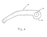
FIG. 4 is a side elevational view of the clamp lever ofFIG. 1 ; -
FIG. 5 is a perspective view of the axle assembly ofFIG. 1 showing in particular, a wheel hub mounted to a front fork; -
FIG. 6 is a perspective view of the axle assembly ofFIG. 1 showing in particular, a wheel hub including a wheel mounted to a front fork, with the clamp lever in a closed position; -
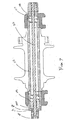
FIG. 7 is a cross-section of another embodiment of the present invention, showing in particular, a follower assembly including a single expander element with a linking member; and -
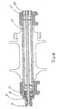
FIG. 8 is a cross-section of yet another embodiment of the present invention, showing in particular, a follower assembly including a single expander element. - Looking to
FIGS. 1-6 , a first embodiment of an axle assembly according to the present invention is designated generally by thereference number 10. Theaxle asse mbly 10 connects afront wheel hub 14 of a bicycle to afront suspension fork 16. Alternatively, theaxle assembly 10 may be used to connect a rear wheel to a bicycle frame or a motorcycle wheel to a motorcycle frame. Theaxle assembly 10 extends coaxially through thewheel hub 14, mounting todropouts suspension fork 16. The axle assembly generally includes atubular body 12 having first andsecond ends wheel hub 14 mounts rotatably on thetubular body 12, and the first andsecond ends tubular body 12 mount to thedropouts fork 16. - In the embodiments of
FIGS. 1-6 , thefirst end 17 of thetubular body 12 is threaded into thedropout 20 of thefork 16, while thesecond end 19 of thetubular body 12 is associated with aclamp lever 24 configured to pivotably clamp theaxle assembly 10 to thefork dropouts axle assembly 10 and thefork suspension 16. - The
tubular body 12 has open-ended slots 25 that are located at bothends ends tubular body 12 to be radially deformable. Thetubular body 12 encloses a rod or askewer 26 having afirst end 28 attached to aclamp lever 24 and asecond end 30 connected--in this embodiment, threaded--to alocknut 32. Athrust washer 40 and afirst expansion washer 42 is wedge-shaped, the larger diameter positioned closed to theclamp lever 24. Disposed between thefirst expansion washer 42 and thetubular body 12 isfirst return spring 44, also coaxially mounted on theskewer 26, for biasing thewasher 42 away from thetubular body 12. Asecond expansion washer 48, shaped similar to thefirst expansion washer 42, is located at theother end 30 of theskewer 26, the smaller diameter of the second expansion washer 48 opposably oriented toward the smaller diameter of thefirst expansion washer 42. Theexpansion washers tubular body 12 upon axial displacement of theexpansion washers tubular body 12. Accordingly, they can assume any number of alternative shapes. Asecond return spring 46, disposed between thetubular body 12 and the second expansion washer 48 biases the second expansion washer 48 away from thetubular body 12. The first andsecond return springs shoulders 27 in thetubular body 12. Thelocknut 32 is threaded onto theend 30 of theskewer 26 and is adjacent to thesecond expansion washer 48. - The
clamp lever 24 includes abore 34 for receiving apivot barrel 36. Thepivot barrel 36 is free to rotate within thebore 34 of theclamp lever 24 and has a threadedhole 38 for attachment to theskewer 26. Theskewer 26 extends through aslot 39 in theclamp lever 24 and is threaded into the threadedhole 38 of thepivot barrel 36. Preferably, the thread length on theskewer 26 is such that it bottoms out upon full engagement with thepivot barrel 36. - The
clamp lever 24 further includes an integratedcam 66 eccentrically disposed about thebore 34. When theclamp lever 24 is pivoted about thebarrel 36, thecam 66 bears against thethrust washer 40 to axially push thethrust washer 40 and thefirst expansion washer 42 toward the tubular body, while at the same time , thebarrel 36 pulls on theskewer 26, thereby also pulling thesecond expansion washer 48 opposably toward thetubular body 12 as well. As the first and thesecond expansion washers tubular body 12 and into engagement with the first and second ends 17, 19 of thetubular body 12, theexpansion slots 25 are outwardly radially deformed outwardly to increase the diameter of thetubular body 12 at thefork dropouts tubular body 12 to seize securely against the dropouts. - The clamping force provided by the
clamp lever 24 and the length of theaxle assembly 10 may be adjusted by moving thelocknut 32 up or down along the threads of theskewer 26. For example, by turning thelocknut 32 clockwise, the clamping force is increased between thetubular body 12 and thefork 16, and by turning thelocknut 32 counterclockwise, the clamping force is decreased between thetubular body 12 and thefork 16. The initial location of thelocknut 32 may be set by the manufacturer so as to provide adequate clamping force once installed on the bicycle. However, this configuration gives the cyclist the option to adjust the location oflocknut 32. - A
bi-directional drive element 56 may be located at theend 19 of thetubular body 12 to allow theaxle assembly 10 to be rotated clockwise or counterclockwise. Thebi-directional element 56 is preferably a projection or tab 60 integrated with the tubular body. Theclamp lever 24 may be positioned to contact either a first orsecond side bi-directional drive element 56 to rotate theaxle assembly 10 clockwise (FIG. 3b ) or counterclockwise (FIG. 3a ). - To mount the
axle assembly 10 on a bicycle, theclamp lever 24 is positioned in an open position, with the clamp lever pivoted away from thefork 16, as shown inFIG. 5 . When theclamp lever 24 is open, theexpansion washers tubular body 12, respectively, by thereturn spring axle assembly 10 to freely slide into thefork dropouts axle assembly 10 is axially inserted through thefirst fork dropout 18, thehub 14 and then into thesecond fork dropout 20. Next, theclamp lever 24 is rotated until thetubular body 12 is completely threaded into thesecond fork dropout 20. As thetubular body 12 is threaded into thefork dropout 20, ashoulder 70 of thetubular body 12 contacts anend 72 of thehub 14, as anotherend 74 of thehub 14 contacts aside 76 of thefork dropout 20 thereby securely seating thetubular body 12 and thehub 14 axially to thefork dropout 20. Once thetubular body 12 is securely threaded to the fordropout 20 axially, theclamp lever 24 is pivoted to a closed position toward the fork 16 (FIG. 6 ) which drives the first andsecond expansion washers ends tubular body 12 to securely clamp thetubular body 12 to thefork dropouts axle assembly 10 is now rigidly connected to thefork dropouts FIG. 3a , theclamp lever 24 is rotated in the directions X and Y to thread and unthread thetubular body 12 to and from thedropout 20, and pivoted in the directions P and Q to clamp and unclamp theaxle assembly 10 to and from thefork dropouts - In the embodiments of
FIGS. 1-6 , a pair of opposably displaceableexpansion washers tubular body 20. As thefirst expansion washer 42 is displaced axially by thecam 66 of theclamp lever 24, and thesecond expansion washer 48 is displaced by theskewer 26, in turn, also displaced by thelever actuator 24, theexpansion washers skewer 26 form a follower assembly responsive to the pivoting motion of thelever actuator 24. - In an alternative embodiment of the invention, shown in
FIG. 7 , the slidingthrust washer 40 and slidingfirst expansion washer 42 of the embodiments ofFIGS. 1-6 are replaced by athrust washer 140 that is axially restrained by a shoulder of atubular body 112. Upon pivoting of thelever actuator 24 toward its closed position (FIG. 6 ), thecam 66 now bears against the axially fixedthrust washer 140 to pull theskewer 26 axially, drawing thesecond expansion washer 48 inwardly to radially deform thetubular body 112 at its first end 117. Accordingly, in the embodiment ofFIG. 7 , thesecond expansion washer 48 andskewer 26 form a follower assembly responsive to the pivoting motion of thelever actuator 24. - In a further embodiment of the invention, shown in
FIG. 8 , thesecond expansion washer 48 of the embodiment ofFIGS. 1-6 is replaced by alocknut 242 that is axially restrained against thefirst end 217 of thetubular body 212. Upon pivoting thelever actuator 24 toward its closed position (FIG. 6 ), thecam 66 bears against the slidingthrust washer 40 to displace the thrust washer and thefirst expansion washer 42 inwardly to radially deform thetubular body 212 at its second end 219. Accordingly, in the embodiment ofFIG. 8 , thefirst expansion washer 42 forms a follower assembly responsive to the pivoting motion of thelever actuator 24. - While this invention has been described by reference to the embodiments shown, it is scope of the inventive concepts described. Accordingly, it is intended that the invention not be limited to the disclosed embodiment, but that it have the full scope permitted by the language of the following claims.
Claims (11)
- An axle assembly (10) for mounting a wheel hub (14) to a vehicle frame comprising:a tubular body (12) having first and second ends (17, 19) mountable to the vehicle frame, the first and second ends (17, 19) configured to be radially deformable to seize against the vehicle frame, the tubular body (12) including open-ended slots (25) disposed at each (17, 19) of the first and second ends of the tubular body;a lever actuator (24); anda follower assembly including a first expander element (42) disposed proximate one (19) of the first and second ends (17, 19) of the tubular body (12),characterized in that the follower further comprises
a second expander element (48) disposed proximate the other (17) of the first and second ends (17, 19) of the tubular body (12), the first and second expander elements (42, 48 being axially displaceable relative to the tubular body (12) in response to pivoting of the lever actuator (24), the first and second expander elements (42, 48) configured to radially deform the first and second ends (17, 19) of the tubular body (12) in response to displacement of the follower assembly by the lever actuator (24). - The axle assembly (10) of claim 1, wherein the tubular body (12) includes a plurality of open-ended slots (25) disposed at one of the first and second ends (17, 19) of the tubular body (12).
- The axle assembly (10) of claim 1 or 2, wherein the lever actuator (24) comprises a cam (66) configured to axially displace the follower assembly in response to pivoting of the lever actuator (24); and the first expander element (42) shaped to radially deform one of the first and second ends (17,19) of the tubular body (12) in response to axial displacement of the follower assembly by the cam (66).
- The axle assembly of claim 3, wherein the first expander element (42) is wedge-shaped.
- The axle assembly (10) of claim 3 or 4, wherein the follower assembly further comprises a barrel (36) rotatably received by the lever actuator (24), the barrel (36) eccentrically disposed within the lever actuator (24) such that the cam (66) axially displaces the follower assembly in response to pivoting of the lever actuator (24).
- The axle assembly (10) of claim 5, further comprising a first spring (44) disposed between the tubular body (12) and the first expander element (42), the spring (44) configured to bias the first expander element (42) away from the tubular body (12).
- The axle assembly of one of claims 3 to 6, wherein the follower assembly further comprises a linking member (40) operably connecting the cam (66) to the first expander element (42).
- The axle assembly of one of claims 1 to 7, wherein the second expander element (48) opposably is displaceable relative to the first expander element (42) and shaped to radially deform the other (17) of the first and second ends (17, 19) of the tubular body (12) in response to axial displacement of the follower assembly by the cam (66).
- The axle assembly (10) of claim 8 further comprising a second spring (46) disposed between the tubular body (12) and the second expander element (48), the second spring (46) configured to bias the second expander element (48) away from the tubular body (12).
- The axle assembly (10) of claim 8 or 9, wherein the tubular body (12) includes a plurality of open-ended slots (25) disposed at the other (17) of the first and second ends (17, 19) of the tubular body (12).
- The axle assembly (10) of one of claims 1 to 10, wherein the tubular body (12) further includes an extension tab (56) protruding from one of the first and second ends (17, 19) of the tubular body (12), the extension tab (56) disposed proximate the lever actuator (24) so as to be engageable thereby to rotate the tubular body (12) in one of a first and second direction.
Applications Claiming Priority (2)
| Application Number | Priority Date | Filing Date | Title |
|---|---|---|---|
| US10/707,157 US7090308B2 (en) | 2003-11-24 | 2003-11-24 | Axle assembly for mounting a wheel to a vehicle |
| PCT/US2004/039796 WO2005051753A1 (en) | 2003-11-24 | 2004-11-24 | Axle assembly for mounting a wheel to a vehicle |
Publications (2)
| Publication Number | Publication Date |
|---|---|
| EP1633622A1 EP1633622A1 (en) | 2006-03-15 |
| EP1633622B1 true EP1633622B1 (en) | 2008-08-27 |
Family
ID=34590814
Family Applications (1)
| Application Number | Title | Priority Date | Filing Date |
|---|---|---|---|
| EP04812336A Expired - Lifetime EP1633622B1 (en) | 2003-11-24 | 2004-11-24 | Axle assembly for mounting a wheel to a vehicle |
Country Status (6)
| Country | Link |
|---|---|
| US (1) | US7090308B2 (en) |
| EP (1) | EP1633622B1 (en) |
| CN (2) | CN102582755B (en) |
| DE (1) | DE602004016153D1 (en) |
| TW (1) | TWI243762B (en) |
| WO (1) | WO2005051753A1 (en) |
Families Citing this family (49)
| Publication number | Priority date | Publication date | Assignee | Title |
|---|---|---|---|---|
| US7090308B2 (en) * | 2003-11-24 | 2006-08-15 | Sram Corporation | Axle assembly for mounting a wheel to a vehicle |
| GB2414971B (en) * | 2004-06-09 | 2006-12-27 | Simon Charles Bartlett | Improvements to wheel clamping assemblies |
| US7562942B2 (en) * | 2005-12-22 | 2009-07-21 | Specialized Bicycle Components, Inc. | Bicycle wheel and release mechanism |
| US7494145B2 (en) * | 2006-10-27 | 2009-02-24 | Answer Products, Inc. | Axle with non-round tapered ends affixed into fork leg dropouts with openings that match the axle ends for a bicycle fork |
| US7537291B2 (en) * | 2007-02-01 | 2009-05-26 | Shimano Inc. | Bicycle wheel securing structure |
| US20080191545A1 (en) * | 2007-02-13 | 2008-08-14 | Fox Factory, Inc. | Axles, Such as for Bicycles |
| US7628416B2 (en) * | 2007-02-21 | 2009-12-08 | Shimano Inc. | Bicycle wheel securing structure |
| US7530645B2 (en) * | 2007-03-01 | 2009-05-12 | Shimano Inc. | Bicycle wheel securing structure |
| DE202007006451U1 (en) | 2007-05-05 | 2007-10-25 | Grätz, Michael | Socket system for wheel attachment |
| US20080284127A1 (en) * | 2007-05-18 | 2008-11-20 | Shimano Inc. | Bicycle wheel securing structure |
| US7673947B2 (en) * | 2007-11-08 | 2010-03-09 | Chin-Chao Chang | Quick release device with biasing unit |
| JP5068634B2 (en) * | 2007-11-29 | 2012-11-07 | 株式会社 栄技研 | Axle assembly |
| US7938421B2 (en) * | 2008-01-17 | 2011-05-10 | Sylvester Yen | Collapsible axle for velocipede |
| US7896381B2 (en) | 2008-03-20 | 2011-03-01 | Trek Bicycle Corporation | Bicycle wheel assembly |
| EP2789530B8 (en) | 2008-05-21 | 2019-03-13 | Fox Factory, Inc. | Methods and apparatus for releasably supporting a vehicle wheel assembly |
| DE102008029136A1 (en) * | 2008-06-19 | 2009-12-24 | Gustav Magenwirth Gmbh & Co. Kg | Bicycle axle arrangement |
| DE102008029135A1 (en) | 2008-06-19 | 2009-12-24 | Gustav Magenwirth Gmbh & Co. Kg | Bicycle axle arrangement |
| US20160114626A1 (en) * | 2009-01-02 | 2016-04-28 | Raphael Schlanger | Handle assembly for an axle |
| DE202009000904U1 (en) | 2009-01-23 | 2010-06-17 | Rose Versand Gmbh | Bike thru axle system |
| US9109245B2 (en) | 2009-04-22 | 2015-08-18 | Viacyte, Inc. | Cell compositions derived from dedifferentiated reprogrammed cells |
| US8113594B2 (en) * | 2009-08-31 | 2012-02-14 | Hayes Bicycle Group Inc. | Apparatus for twist-to-lock retention of a wheel |
| US8820853B1 (en) | 2010-03-25 | 2014-09-02 | Eko Sport, Inc. | Wheel axle assembly |
| US9045192B2 (en) * | 2010-05-14 | 2015-06-02 | Raphael Schlanger | Quick release hub assembly |
| US8075010B2 (en) | 2010-05-14 | 2011-12-13 | Specialized Bicycle Components, Inc. | Rear axle system for bicycle |
| US8573879B2 (en) * | 2011-06-15 | 2013-11-05 | Chin-Chao Chang | Quick-release device |
| US8573878B2 (en) * | 2011-06-15 | 2013-11-05 | Chin-Chao Chang | Quick-release device |
| US8820854B2 (en) * | 2011-08-03 | 2014-09-02 | Trek Bicycle Corporation | Bicycle wheel quick release assembly with clockable handle |
| CH706591A2 (en) * | 2012-06-04 | 2013-12-13 | Patrik Voegtli | Axle means for bicycles. |
| TWI439388B (en) * | 2012-06-08 | 2014-06-01 | A Pro Tech Co Ltd | Bicycle quick release anti - loosening device |
| US9120349B2 (en) * | 2012-06-14 | 2015-09-01 | Chin-Chao Chang | Quick-release device for use on a bicycle |
| TWI582002B (en) * | 2013-09-12 | 2017-05-11 | Shimano Kk | Bicycle wheel fixing mechanism |
| USD736681S1 (en) * | 2014-03-14 | 2015-08-18 | Showa Corporation | Axle holder for motorcycle |
| FR3036312B1 (en) | 2015-05-21 | 2017-06-02 | Cycles Lapierre | DERAILLEUR'S PATTERN |
| TWI573701B (en) * | 2015-05-22 | 2017-03-11 | Raphael Schlanger | Quick release skewer assmbly |
| FR3037919B1 (en) * | 2015-06-29 | 2017-07-28 | Mavic Sas | FIXING PIN AND HUB FOR CYCLE WHEEL |
| DE202016102676U1 (en) | 2015-08-05 | 2016-08-23 | Ulrich Fahl | Improved quick-release axle for two-wheelers |
| DE202015005524U1 (en) * | 2015-08-05 | 2015-10-02 | tune U. Fahl e.K. | Quick release for bicycles with adjustment function |
| JP2017030669A (en) * | 2015-08-05 | 2017-02-09 | 株式会社シマノ | Bicycle wheel fixing mechanism |
| US9815327B2 (en) * | 2015-09-03 | 2017-11-14 | National Taipei University Of Technology | Quick release apparatus for bicycle tire or tube |
| US10329011B2 (en) * | 2015-10-02 | 2019-06-25 | Goodrich Corporation | Axle saddle |
| DE202015106650U1 (en) | 2015-12-07 | 2017-03-08 | Ulrich Fahl | Quick-release axle for two-wheelers |
| ITUA20161561A1 (en) * | 2016-03-11 | 2017-09-11 | Campagnolo Srl | Device for mounting a wheel on a bicycle frame |
| US20170341700A1 (en) * | 2016-05-26 | 2017-11-30 | GM Global Technology Operations LLC | Integrated e-bike axle locking system |
| DE202016104865U1 (en) | 2016-09-02 | 2017-12-06 | Tune Gmbh | Clamping device for thru axles |
| USD826796S1 (en) * | 2016-11-14 | 2018-08-28 | Showa Corporation | Axle holder for motorcycle |
| DE102017116011B3 (en) | 2017-07-17 | 2018-12-20 | Tune Gmbh | Thru axle for two-wheelers |
| DE202017006144U1 (en) | 2017-11-28 | 2017-12-15 | Janik Voth | Quick release device for thru axles |
| US11884356B2 (en) * | 2020-07-08 | 2024-01-30 | Shun Xin Co., Ltd. | Bicycle quick release device |
| DE102022103627B4 (en) | 2022-02-16 | 2024-05-16 | Porsche Ebike Performance Gmbh | Drive device for an electric bicycle and electric bicycle |
Family Cites Families (27)
| Publication number | Priority date | Publication date | Assignee | Title |
|---|---|---|---|---|
| US622766A (en) * | 1899-04-11 | harris | ||
| US711205A (en) * | 1901-02-05 | 1902-10-14 | Paul N Goodrich | Adjustable bicycle saddle-post. |
| US720658A (en) * | 1902-03-29 | 1903-02-17 | Sylvester Bobo | Bicycle seat-post. |
| US3807761A (en) * | 1972-12-26 | 1974-04-30 | Schwinn Bicycle Co | Safety mounting for quick-release hubs |
| JPS5222745Y2 (en) * | 1973-02-20 | 1977-05-25 | ||
| IT1008629B (en) * | 1973-12-21 | 1976-11-30 | Sigla Spa P | BICYCLE WITH SHELL STRUCTURE MADE WITH PRINTABLE MATERIAL |
| US4028915A (en) * | 1976-02-17 | 1977-06-14 | Far Out Products Ltd. | Lever arm lock for quick release hub assembly |
| JPS5849436B2 (en) * | 1980-08-06 | 1983-11-04 | マエダ工業株式会社 | Kuitscleries hub for bicycles |
| DE3145319A1 (en) * | 1981-11-14 | 1983-05-26 | Toge-Dübel A.Gerhard GmbH, 8500 Nürnberg | Expanding dowel |
| JPS62241701A (en) * | 1986-04-11 | 1987-10-22 | Maeda Kogyo Kk | Quick releasing device for hub for bicycle |
| DE9104431U1 (en) * | 1991-04-11 | 1991-08-22 | K.W. Hochschorner GmbH, 8033 Martinsried | Quick release for a bicycle |
| MX9202666A (en) * | 1991-06-06 | 1994-04-29 | F E Qr Corp Sa | QUICK RELEASE AND SELF-ALIGNMENT WHEEL MOUNTING SYSTEM. |
| US5165762A (en) * | 1991-09-16 | 1992-11-24 | Phillips Harley V | Bicycle wheel quick-release apparatus |
| US5383716A (en) * | 1993-09-16 | 1995-01-24 | S.A.F.E.-Q.R. Corporation | Quick-release bicycle axle fastener |
| US5673925A (en) | 1994-01-21 | 1997-10-07 | Stewart; Christopher R. | Quick release skewer system |
| JPH08175453A (en) | 1994-12-21 | 1996-07-09 | Kayaba Ind Co Ltd | Axle connection structure |
| US5567020A (en) * | 1995-06-26 | 1996-10-22 | S.A.F.E.-Q.R. Corporation | Quick-release bicycle axle fastener |
| US5653512A (en) * | 1995-10-12 | 1997-08-05 | S.A.F.E.-Q.R. Corporation | Quick-release bicycle axle fastener nut |
| US5961186A (en) * | 1996-12-02 | 1999-10-05 | S.A.F.E.-Q.R. Corporation | Quick-release bicycle axle fastener |
| US6260931B1 (en) * | 1997-09-23 | 2001-07-17 | John V. Stewart | Safe quick-release bicycle axle fastener |
| US6241322B1 (en) * | 1998-06-05 | 2001-06-05 | Cal M. Phillips | Quick-release bicycle axle fastener nut |
| US6296322B1 (en) * | 1998-11-10 | 2001-10-02 | Marzocchi, S.P.A. | Quick release dropout and wheel hub assembly |
| CN2373296Y (en) * | 1998-12-02 | 2000-04-12 | 李绍朋 | Bearing axle for bicycle and tricycle |
| CN2363909Y (en) * | 1999-05-05 | 2000-02-16 | 捷安特(中国)有限公司 | Bottom bracket axle assembly for child's bicycle |
| US6276760B1 (en) | 1999-06-28 | 2001-08-21 | Richard C. Everett | Quick release hub for cycle wheel |
| US6761417B2 (en) * | 2002-10-31 | 2004-07-13 | Michael L. Denby | Quick release assembly |
| US7090308B2 (en) * | 2003-11-24 | 2006-08-15 | Sram Corporation | Axle assembly for mounting a wheel to a vehicle |
-
2003
- 2003-11-24 US US10/707,157 patent/US7090308B2/en not_active Expired - Lifetime
-
2004
- 2004-11-16 TW TW093135094A patent/TWI243762B/en not_active IP Right Cessation
- 2004-11-24 DE DE602004016153T patent/DE602004016153D1/en not_active Expired - Lifetime
- 2004-11-24 CN CN201210056562.9A patent/CN102582755B/en not_active Expired - Fee Related
- 2004-11-24 WO PCT/US2004/039796 patent/WO2005051753A1/en not_active Ceased
- 2004-11-24 EP EP04812336A patent/EP1633622B1/en not_active Expired - Lifetime
- 2004-11-24 CN CN2004800118385A patent/CN1784336B/en not_active Expired - Fee Related
Also Published As
| Publication number | Publication date |
|---|---|
| US7090308B2 (en) | 2006-08-15 |
| US20050110335A1 (en) | 2005-05-26 |
| DE602004016153D1 (en) | 2008-10-09 |
| TW200523142A (en) | 2005-07-16 |
| CN102582755B (en) | 2015-10-14 |
| EP1633622A1 (en) | 2006-03-15 |
| TWI243762B (en) | 2005-11-21 |
| CN102582755A (en) | 2012-07-18 |
| CN1784336B (en) | 2012-05-23 |
| WO2005051753A1 (en) | 2005-06-09 |
| CN1784336A (en) | 2006-06-07 |
Similar Documents
| Publication | Publication Date | Title |
|---|---|---|
| US7090308B2 (en) | Axle assembly for mounting a wheel to a vehicle | |
| US5269549A (en) | Suspension for bicycles | |
| US7992889B2 (en) | Convertible stroller-cycle | |
| US5193832A (en) | Suspension for bicyles | |
| US7669871B2 (en) | Bicycle wheel securing adapter and bicycle fork using the same | |
| US5201244A (en) | Bicycle handlebar stem extender | |
| US6409281B1 (en) | Bicycle hub with spacer and detachable freewheel | |
| US6296322B1 (en) | Quick release dropout and wheel hub assembly | |
| US20060189424A1 (en) | Bicycle rear derailleur guard | |
| US5482306A (en) | Chainless transmission mechanism for bicycles | |
| US10189306B2 (en) | Rear hub and bicyclic axle | |
| US20090283986A1 (en) | Rear fork | |
| WO2016168207A1 (en) | Tricycle apparatus with rear independent transverse suspension and related components | |
| WO1993013974A1 (en) | Rear suspension for bicycles | |
| US20050212251A1 (en) | Motorcycle fork bottom which is stiffer front-to-back than side-to-side | |
| US7347438B2 (en) | Cycle bracket having multiple drop-outs | |
| US20200130764A1 (en) | Bicycle rack assembly for a suspension fork | |
| US20160023709A1 (en) | Motorcycle to reverse trike conversion kit and method | |
| CA3000703A1 (en) | Quick release mechanism and bicycle using the same | |
| USRE35401E (en) | Suspension for bicycles | |
| NL1008338C1 (en) | Suspension system for a bicycle frame. | |
| US11407469B2 (en) | Collapsible bicycle frame | |
| WO2000012376A1 (en) | Full floating double action bicycle suspension system | |
| US20260021866A1 (en) | Vent seal device for a bicycle | |
| EP1362781A1 (en) | Bicycle |
Legal Events
| Date | Code | Title | Description |
|---|---|---|---|
| PUAI | Public reference made under article 153(3) epc to a published international application that has entered the european phase |
Free format text: ORIGINAL CODE: 0009012 |
|
| 17P | Request for examination filed |
Effective date: 20051208 |
|
| AK | Designated contracting states |
Kind code of ref document: A1 Designated state(s): DE FR NL |
|
| 17Q | First examination report despatched |
Effective date: 20060413 |
|
| DAX | Request for extension of the european patent (deleted) | ||
| RBV | Designated contracting states (corrected) |
Designated state(s): DE FR NL |
|
| GRAP | Despatch of communication of intention to grant a patent |
Free format text: ORIGINAL CODE: EPIDOSNIGR1 |
|
| GRAJ | Information related to disapproval of communication of intention to grant by the applicant or resumption of examination proceedings by the epo deleted |
Free format text: ORIGINAL CODE: EPIDOSDIGR1 |
|
| GRAP | Despatch of communication of intention to grant a patent |
Free format text: ORIGINAL CODE: EPIDOSNIGR1 |
|
| GRAS | Grant fee paid |
Free format text: ORIGINAL CODE: EPIDOSNIGR3 |
|
| GRAA | (expected) grant |
Free format text: ORIGINAL CODE: 0009210 |
|
| AK | Designated contracting states |
Kind code of ref document: B1 Designated state(s): DE FR NL |
|
| REF | Corresponds to: |
Ref document number: 602004016153 Country of ref document: DE Date of ref document: 20081009 Kind code of ref document: P |
|
| RAP2 | Party data changed (patent owner data changed or rights of a patent transferred) |
Owner name: SRAM, LLC. |
|
| NLS | Nl: assignments of ep-patents |
Owner name: SRAM, LLC. Effective date: 20081222 |
|
| PLBE | No opposition filed within time limit |
Free format text: ORIGINAL CODE: 0009261 |
|
| STAA | Information on the status of an ep patent application or granted ep patent |
Free format text: STATUS: NO OPPOSITION FILED WITHIN TIME LIMIT |
|
| 26N | No opposition filed |
Effective date: 20090528 |
|
| REG | Reference to a national code |
Ref country code: FR Ref legal event code: TP |
|
| REG | Reference to a national code |
Ref country code: FR Ref legal event code: PLFP Year of fee payment: 12 |
|
| REG | Reference to a national code |
Ref country code: FR Ref legal event code: PLFP Year of fee payment: 13 |
|
| PGFP | Annual fee paid to national office [announced via postgrant information from national office to epo] |
Ref country code: DE Payment date: 20161116 Year of fee payment: 13 Ref country code: NL Payment date: 20161110 Year of fee payment: 13 Ref country code: FR Payment date: 20161014 Year of fee payment: 13 |
|
| REG | Reference to a national code |
Ref country code: DE Ref legal event code: R119 Ref document number: 602004016153 Country of ref document: DE |
|
| REG | Reference to a national code |
Ref country code: NL Ref legal event code: MM Effective date: 20171201 |
|
| REG | Reference to a national code |
Ref country code: FR Ref legal event code: ST Effective date: 20180731 |
|
| PG25 | Lapsed in a contracting state [announced via postgrant information from national office to epo] |
Ref country code: NL Free format text: LAPSE BECAUSE OF NON-PAYMENT OF DUE FEES Effective date: 20171201 Ref country code: FR Free format text: LAPSE BECAUSE OF NON-PAYMENT OF DUE FEES Effective date: 20171130 Ref country code: DE Free format text: LAPSE BECAUSE OF NON-PAYMENT OF DUE FEES Effective date: 20180602 |
|
| P01 | Opt-out of the competence of the unified patent court (upc) registered |
Effective date: 20230524 |