EP1633461B1 - Method of operating a system comprising a diesel engine and a catalyst for exhaust gas purification - Google Patents
Method of operating a system comprising a diesel engine and a catalyst for exhaust gas purification Download PDFInfo
- Publication number
- EP1633461B1 EP1633461B1 EP04739251A EP04739251A EP1633461B1 EP 1633461 B1 EP1633461 B1 EP 1633461B1 EP 04739251 A EP04739251 A EP 04739251A EP 04739251 A EP04739251 A EP 04739251A EP 1633461 B1 EP1633461 B1 EP 1633461B1
- Authority
- EP
- European Patent Office
- Prior art keywords
- exhaust gas
- catalyst
- engine
- gas temperature
- temperature
- Prior art date
- Legal status (The legal status is an assumption and is not a legal conclusion. Google has not performed a legal analysis and makes no representation as to the accuracy of the status listed.)
- Active
Links
- 239000003054 catalyst Substances 0.000 title claims abstract description 67
- 238000000034 method Methods 0.000 title claims abstract description 18
- 238000000746 purification Methods 0.000 title claims abstract description 8
- 230000032683 aging Effects 0.000 claims abstract description 24
- 230000003197 catalytic effect Effects 0.000 claims abstract description 11
- 230000007423 decrease Effects 0.000 claims abstract description 8
- 229930195733 hydrocarbon Natural products 0.000 claims description 15
- 150000002430 hydrocarbons Chemical class 0.000 claims description 15
- 238000002485 combustion reaction Methods 0.000 claims description 7
- 239000007789 gas Substances 0.000 description 48
- 239000003344 environmental pollutant Substances 0.000 description 15
- 231100000719 pollutant Toxicity 0.000 description 15
- MWUXSHHQAYIFBG-UHFFFAOYSA-N nitrogen oxide Inorganic materials O=[N] MWUXSHHQAYIFBG-UHFFFAOYSA-N 0.000 description 11
- 230000003647 oxidation Effects 0.000 description 10
- 238000007254 oxidation reaction Methods 0.000 description 10
- 239000002245 particle Substances 0.000 description 10
- UGFAIRIUMAVXCW-UHFFFAOYSA-N Carbon monoxide Chemical compound [O+]#[C-] UGFAIRIUMAVXCW-UHFFFAOYSA-N 0.000 description 9
- 229910002091 carbon monoxide Inorganic materials 0.000 description 9
- 238000006243 chemical reaction Methods 0.000 description 9
- 238000002347 injection Methods 0.000 description 8
- 239000007924 injection Substances 0.000 description 8
- BASFCYQUMIYNBI-UHFFFAOYSA-N platinum Chemical compound [Pt] BASFCYQUMIYNBI-UHFFFAOYSA-N 0.000 description 8
- 238000011068 loading method Methods 0.000 description 7
- 239000000446 fuel Substances 0.000 description 5
- RAHZWNYVWXNFOC-UHFFFAOYSA-N Sulphur dioxide Chemical compound O=S=O RAHZWNYVWXNFOC-UHFFFAOYSA-N 0.000 description 4
- 229910052697 platinum Inorganic materials 0.000 description 4
- 239000004071 soot Substances 0.000 description 4
- AKEJUJNQAAGONA-UHFFFAOYSA-N sulfur trioxide Chemical compound O=S(=O)=O AKEJUJNQAAGONA-UHFFFAOYSA-N 0.000 description 4
- QVGXLLKOCUKJST-UHFFFAOYSA-N atomic oxygen Chemical compound [O] QVGXLLKOCUKJST-UHFFFAOYSA-N 0.000 description 3
- 239000000470 constituent Substances 0.000 description 3
- 238000012986 modification Methods 0.000 description 3
- 230000004048 modification Effects 0.000 description 3
- 229910000510 noble metal Inorganic materials 0.000 description 3
- 229910052760 oxygen Inorganic materials 0.000 description 3
- 239000001301 oxygen Substances 0.000 description 3
- 238000011144 upstream manufacturing Methods 0.000 description 3
- OYPRJOBELJOOCE-UHFFFAOYSA-N Calcium Chemical compound [Ca] OYPRJOBELJOOCE-UHFFFAOYSA-N 0.000 description 2
- XEEYBQQBJWHFJM-UHFFFAOYSA-N Iron Chemical compound [Fe] XEEYBQQBJWHFJM-UHFFFAOYSA-N 0.000 description 2
- PXHVJJICTQNCMI-UHFFFAOYSA-N Nickel Chemical compound [Ni] PXHVJJICTQNCMI-UHFFFAOYSA-N 0.000 description 2
- OAICVXFJPJFONN-UHFFFAOYSA-N Phosphorus Chemical compound [P] OAICVXFJPJFONN-UHFFFAOYSA-N 0.000 description 2
- 239000011575 calcium Substances 0.000 description 2
- 229910052791 calcium Inorganic materials 0.000 description 2
- 230000003247 decreasing effect Effects 0.000 description 2
- 239000000203 mixture Substances 0.000 description 2
- 150000002894 organic compounds Chemical class 0.000 description 2
- 229910052698 phosphorus Inorganic materials 0.000 description 2
- 239000011574 phosphorus Substances 0.000 description 2
- 231100000572 poisoning Toxicity 0.000 description 2
- 230000000607 poisoning effect Effects 0.000 description 2
- OKTJSMMVPCPJKN-UHFFFAOYSA-N Carbon Chemical compound [C] OKTJSMMVPCPJKN-UHFFFAOYSA-N 0.000 description 1
- QAOWNCQODCNURD-UHFFFAOYSA-L Sulfate Chemical compound [O-]S([O-])(=O)=O QAOWNCQODCNURD-UHFFFAOYSA-L 0.000 description 1
- NINIDFKCEFEMDL-UHFFFAOYSA-N Sulfur Chemical compound [S] NINIDFKCEFEMDL-UHFFFAOYSA-N 0.000 description 1
- HCHKCACWOHOZIP-UHFFFAOYSA-N Zinc Chemical compound [Zn] HCHKCACWOHOZIP-UHFFFAOYSA-N 0.000 description 1
- 230000001133 acceleration Effects 0.000 description 1
- 239000000654 additive Substances 0.000 description 1
- 229910052799 carbon Inorganic materials 0.000 description 1
- 238000001816 cooling Methods 0.000 description 1
- 230000001419 dependent effect Effects 0.000 description 1
- 230000006866 deterioration Effects 0.000 description 1
- TXKMVPPZCYKFAC-UHFFFAOYSA-N disulfur monoxide Inorganic materials O=S=S TXKMVPPZCYKFAC-UHFFFAOYSA-N 0.000 description 1
- 230000000694 effects Effects 0.000 description 1
- 238000009472 formulation Methods 0.000 description 1
- 229910052742 iron Inorganic materials 0.000 description 1
- 239000011133 lead Substances 0.000 description 1
- 239000010687 lubricating oil Substances 0.000 description 1
- 238000004519 manufacturing process Methods 0.000 description 1
- 229910052751 metal Inorganic materials 0.000 description 1
- 239000002184 metal Substances 0.000 description 1
- 239000010705 motor oil Substances 0.000 description 1
- 229910052759 nickel Inorganic materials 0.000 description 1
- 239000003960 organic solvent Substances 0.000 description 1
- 230000008929 regeneration Effects 0.000 description 1
- 238000011069 regeneration method Methods 0.000 description 1
- 239000000126 substance Substances 0.000 description 1
- 229910052717 sulfur Inorganic materials 0.000 description 1
- 239000011593 sulfur Substances 0.000 description 1
- XTQHKBHJIVJGKJ-UHFFFAOYSA-N sulfur monoxide Chemical compound S=O XTQHKBHJIVJGKJ-UHFFFAOYSA-N 0.000 description 1
- 229910052725 zinc Inorganic materials 0.000 description 1
- 239000011701 zinc Substances 0.000 description 1
Images


Classifications
-
- F—MECHANICAL ENGINEERING; LIGHTING; HEATING; WEAPONS; BLASTING
- F01—MACHINES OR ENGINES IN GENERAL; ENGINE PLANTS IN GENERAL; STEAM ENGINES
- F01N—GAS-FLOW SILENCERS OR EXHAUST APPARATUS FOR MACHINES OR ENGINES IN GENERAL; GAS-FLOW SILENCERS OR EXHAUST APPARATUS FOR INTERNAL COMBUSTION ENGINES
- F01N11/00—Monitoring or diagnostic devices for exhaust-gas treatment apparatus, e.g. for catalytic activity
- F01N11/002—Monitoring or diagnostic devices for exhaust-gas treatment apparatus, e.g. for catalytic activity the diagnostic devices measuring or estimating temperature or pressure in, or downstream of the exhaust apparatus
-
- B—PERFORMING OPERATIONS; TRANSPORTING
- B01—PHYSICAL OR CHEMICAL PROCESSES OR APPARATUS IN GENERAL
- B01D—SEPARATION
- B01D53/00—Separation of gases or vapours; Recovering vapours of volatile solvents from gases; Chemical or biological purification of waste gases, e.g. engine exhaust gases, smoke, fumes, flue gases, aerosols
- B01D53/34—Chemical or biological purification of waste gases
- B01D53/92—Chemical or biological purification of waste gases of engine exhaust gases
- B01D53/94—Chemical or biological purification of waste gases of engine exhaust gases by catalytic processes
- B01D53/9495—Controlling the catalytic process
-
- F—MECHANICAL ENGINEERING; LIGHTING; HEATING; WEAPONS; BLASTING
- F02—COMBUSTION ENGINES; HOT-GAS OR COMBUSTION-PRODUCT ENGINE PLANTS
- F02D—CONTROLLING COMBUSTION ENGINES
- F02D41/00—Electrical control of supply of combustible mixture or its constituents
- F02D41/02—Circuit arrangements for generating control signals
- F02D41/021—Introducing corrections for particular conditions exterior to the engine
- F02D41/0235—Introducing corrections for particular conditions exterior to the engine in relation with the state of the exhaust gas treating apparatus
- F02D41/024—Introducing corrections for particular conditions exterior to the engine in relation with the state of the exhaust gas treating apparatus to increase temperature of the exhaust gas treating apparatus
-
- F—MECHANICAL ENGINEERING; LIGHTING; HEATING; WEAPONS; BLASTING
- F01—MACHINES OR ENGINES IN GENERAL; ENGINE PLANTS IN GENERAL; STEAM ENGINES
- F01N—GAS-FLOW SILENCERS OR EXHAUST APPARATUS FOR MACHINES OR ENGINES IN GENERAL; GAS-FLOW SILENCERS OR EXHAUST APPARATUS FOR INTERNAL COMBUSTION ENGINES
- F01N2430/00—Influencing exhaust purification, e.g. starting of catalytic reaction, filter regeneration, or the like, by controlling engine operating characteristics
- F01N2430/08—Influencing exhaust purification, e.g. starting of catalytic reaction, filter regeneration, or the like, by controlling engine operating characteristics by modifying ignition or injection timing
-
- F—MECHANICAL ENGINEERING; LIGHTING; HEATING; WEAPONS; BLASTING
- F01—MACHINES OR ENGINES IN GENERAL; ENGINE PLANTS IN GENERAL; STEAM ENGINES
- F01N—GAS-FLOW SILENCERS OR EXHAUST APPARATUS FOR MACHINES OR ENGINES IN GENERAL; GAS-FLOW SILENCERS OR EXHAUST APPARATUS FOR INTERNAL COMBUSTION ENGINES
- F01N2550/00—Monitoring or diagnosing the deterioration of exhaust systems
- F01N2550/02—Catalytic activity of catalytic converters
-
- F—MECHANICAL ENGINEERING; LIGHTING; HEATING; WEAPONS; BLASTING
- F02—COMBUSTION ENGINES; HOT-GAS OR COMBUSTION-PRODUCT ENGINE PLANTS
- F02B—INTERNAL-COMBUSTION PISTON ENGINES; COMBUSTION ENGINES IN GENERAL
- F02B3/00—Engines characterised by air compression and subsequent fuel addition
- F02B3/06—Engines characterised by air compression and subsequent fuel addition with compression ignition
-
- F—MECHANICAL ENGINEERING; LIGHTING; HEATING; WEAPONS; BLASTING
- F02—COMBUSTION ENGINES; HOT-GAS OR COMBUSTION-PRODUCT ENGINE PLANTS
- F02D—CONTROLLING COMBUSTION ENGINES
- F02D9/00—Controlling engines by throttling air or fuel-and-air induction conduits or exhaust conduits
- F02D9/02—Controlling engines by throttling air or fuel-and-air induction conduits or exhaust conduits concerning induction conduits
- F02D2009/0201—Arrangements; Control features; Details thereof
- F02D2009/0222—Exhaust gas temperature
-
- F—MECHANICAL ENGINEERING; LIGHTING; HEATING; WEAPONS; BLASTING
- F02—COMBUSTION ENGINES; HOT-GAS OR COMBUSTION-PRODUCT ENGINE PLANTS
- F02D—CONTROLLING COMBUSTION ENGINES
- F02D9/00—Controlling engines by throttling air or fuel-and-air induction conduits or exhaust conduits
- F02D9/02—Controlling engines by throttling air or fuel-and-air induction conduits or exhaust conduits concerning induction conduits
- F02D2009/0201—Arrangements; Control features; Details thereof
- F02D2009/0237—Increasing combustion chamber gas temperature
-
- Y—GENERAL TAGGING OF NEW TECHNOLOGICAL DEVELOPMENTS; GENERAL TAGGING OF CROSS-SECTIONAL TECHNOLOGIES SPANNING OVER SEVERAL SECTIONS OF THE IPC; TECHNICAL SUBJECTS COVERED BY FORMER USPC CROSS-REFERENCE ART COLLECTIONS [XRACs] AND DIGESTS
- Y02—TECHNOLOGIES OR APPLICATIONS FOR MITIGATION OR ADAPTATION AGAINST CLIMATE CHANGE
- Y02T—CLIMATE CHANGE MITIGATION TECHNOLOGIES RELATED TO TRANSPORTATION
- Y02T10/00—Road transport of goods or passengers
- Y02T10/10—Internal combustion engine [ICE] based vehicles
- Y02T10/12—Improving ICE efficiencies
-
- Y—GENERAL TAGGING OF NEW TECHNOLOGICAL DEVELOPMENTS; GENERAL TAGGING OF CROSS-SECTIONAL TECHNOLOGIES SPANNING OVER SEVERAL SECTIONS OF THE IPC; TECHNICAL SUBJECTS COVERED BY FORMER USPC CROSS-REFERENCE ART COLLECTIONS [XRACs] AND DIGESTS
- Y02—TECHNOLOGIES OR APPLICATIONS FOR MITIGATION OR ADAPTATION AGAINST CLIMATE CHANGE
- Y02T—CLIMATE CHANGE MITIGATION TECHNOLOGIES RELATED TO TRANSPORTATION
- Y02T10/00—Road transport of goods or passengers
- Y02T10/10—Internal combustion engine [ICE] based vehicles
- Y02T10/40—Engine management systems
Definitions
- the present invention relates to a method of operating a drive system comprising a diesel engine provided with a diesel oxidation catalyst for purifying the exhaust gases from the engine. Similar methods are described in EP-A-0 498 598 and US-A-5 693 877 .
- the main pollutants from diesel engines are, apart from the very small amounts of hydrocarbons (HC) and carbon monoxide (CO), nitrogen oxides (NOx) and soot particles (PM).
- the soot particles are composed of a constituent which is soluble in organic solvents and a constituent which is insoluble.
- the soluble part comprises a large number of different hydrocarbons which are condensed or adsorbed or absorbed on the particle core.
- the insoluble component comprises sulfur trioxide or sulfate, carbon, abraded metal (for example iron and nickel) and small amounts of other oxides formed from additives in lubricating oil and in the fuel (for example zinc, calcium, phosphorus).
- Sulfur trioxide is formed by oxidation of sulfur dioxide over the catalyst as a function of temperature, noble metal loading and exhaust gas flow.
- a particular characteristic of diesel engines is the high oxygen content of the exhaust gas. While the exhaust gas of stoichiometrically operated gasoline engines contains only about 0.7% by volume of oxygen, the exhaust gas of diesel engines can contain from 6 to 15% by volume of oxygen.
- the ratio of the various pollutants in the diesel exhaust gas to one another depends on the type of diesel engine and its mode of operation. In principle, what has been said above applies both to stationary diesel engines and to diesel engines in motor vehicles for light and heavy duties.
- diesel oxidation catalyst which burns the emitted hydrocarbons, carbon monoxide and also part of the soluble organic compounds adsorbed on the soot particles.
- the oxidation function of diesel oxidation catalysts is designed so that although they oxidize the organic compounds and carbon monoxide, they do not convert the nitrogen oxides and sulfur dioxide into more highly oxidized species. Together with the remaining proportion of the particles, the nitrogen oxides and sulfur oxide leave the catalyst virtually unchanged.
- a typical representative of such catalysts is described in DE 39 40 758 A1 ( US 5,157,007 ).
- the conversion of pollutants by means of such catalysts is strongly dependent on the temperature.
- the conversion of the pollutants increases with increasing exhaust gas temperature.
- the temperature at which a prescribed percentage, usually 50%, of a pollutant is reacted is referred to as the light-off temperature of the catalyst for the conversion of this pollutant. It is an important parameter for describing the catalytic activity of the catalyst.
- the aging state of the catalysts has a significant influence on the degree of conversion for the various pollutants.
- the catalytic activity of the catalysts decreases.
- Aging can comprise damage caused by thermal overloading and/or poisoning by poisoning elements such as lead, phosphorus, calcium and sulfur, some of which are present in the fuel or are constituents of motor oil.
- the catalysts have to be able to ensure adherence to particular limit values for pollutant conversion even after the vehicle has been driven for up to 150 000 miles. This requirement is usually fulfilled by over-dimensioning of the fresh catalyst.
- it can be designed so as to be significantly larger than would be necessary on the assumption of its fresh activity, or the catalyst formulation in terms of composition and noble metal loading is adapted appropriately.
- This object is achieved by a method in which the aging-induced decrease in the catalytic activity of the catalyst is compensated at least part of the time by increasing the exhaust gas temperature of the engine.
- the invention is described below for a drive system comprising a diesel engine and an exhaust gas purification unit containing a diesel oxidation catalyst.
- NEDC New European Driving Cycle
- Figure 1 shows the exhaust gas temperature of a 1.4 l diesel engine as a function of the test time for the first 500 seconds of the NEDC test.
- the curve denoted as "reference” records the actual exhaust gas temperatures of the diesel engine.
- This engine is equipped with a standard honeycomb catalyst having a volume of 2.4 l, a cell density of 62 cm -2 and a platinum loading of 2.83 g/l (80 g/ft 3 ) for exhaust gas purification.
- Figure 2 shows modeling calculations by the inventors on the CO emission of the diesel engine during the test for different platinum loadings of the diesel oxidation catalyst.
- the emission values were calculated for exhaust gas temperatures decreased or increased linearly relative to the reference case.
- the emission values for the abscissa value of 1.00 indicate the CO emission of the diesel engine at the original exhaust gas temperature corresponding to the reference curve of figure 1 for different platinum loadings.
- an exhaust gas temperature of the diesel engine increased or reduced linearly relative to the reference curve was assumed.
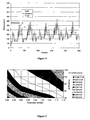
- the abscissa values 0.85 and 1.15 these temperature curves are shown in figure 1 , curve a) for an exhaust gas temperature reduced linearly by 15% and curve b) for an exhaust gas temperature increased linearly by 15%.
- the exhaust gas temperatures of a diesel engine can be increased by means of various measures.
- the exhaust gas temperature of the engine can be increased either immediately after the cold start or after some time delay.
- preference is given to selecting measures which have only a small influence on the emission behavior of the engine so as to prevent excessive emission of pollutants during the cold start phase.
- measures which lead to somewhat higher emission values since pollutants are reliably converted into nonpolluting substances by the method of the invention.
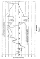
- Figure 3 shows this by way of example for a heavy duty vehicle engine.
- the temperature curve denoted by "production model” indicates the exhaust gas temperature upstream of a particle filter for a particular driving cycle.
- the exhaust gas temperature during this same driving cycle can be increased by about 100°C by choking the engine (curve "modified engine”).
- This causes an additional fuel consumption of about 10%.
- the method of the invention generally requires a temperature increase of only 20 K or less to compensate for the aging of the catalyst. The additional fuel consumption due to the method will therefore be correspondingly lower.
- the aging-induced decrease in the catalytic activity can be determined in various ways.
- an average aging behavior for a series of catalysts can be measured beforehand as a function of the time of operation.
- the aging state can be determined by continuously measuring the pollutant conversion by means of a directly measuring gas sensor system and fitting the data to a catalyst model entered in the engine control system.
- the necessary modifications to the operating parameters which ensure a sufficient increase in the exhaust gas temperature for the respective aging state can be entered in the engine control system as a function of the aging state determined.
- the gas sensor system for determining the pollutant conversion can, for example, comprise a sensor upstream of the catalyst and a sensor downstream of the catalyst for the pollutant concerned (CO, HC or NO).
- the sensor upstream of the catalyst can be omitted if the pollutant concentrations in the exhaust gas for any operating point of the engine have previously been entered in the form of performance characteristics in the engine control system.
- the aging state of the catalyst can also be determined discontinuously, i.e. after a particular distance covered or a particular number of hours of operation.
- the heat evolved over the catalyst on post-injection of a defined amount of hydrocarbons can be measured.
- the fresh catalyst burns the additional hydrocarbons better than the aged catalyst and therefore leads to a greater increase in the temperature of the exhaust gas as a result of this process.
- the necessary changes to the operating parameters of the engine can be determined directly as follows: the heat evolved in the combustion of a given amount of hydrocarbons over the catalyst is firstly measured and compared with the heat evolved over the fresh catalyst at this operating point. In the case of a reduced amount of heat evolved compared to the fresh catalyst, the exhaust gas temperature of the engine prevailing at this operating point is increased without altering the torque by engine measures until the newly measured heat evolved over the aged catalyst corresponds to the heat evolved over the fresh catalyst. From this it is possible to determine the factor by which the exhaust gas temperature has to be increased to compensate for the aging-induced decrease in performance of the catalyst. In this case too, the necessary modifications to the process parameters which ensure a sufficient increase in the exhaust gas temperature for the respective aging state at all other operating points can be entered in the engine control system as a function of the factor determined.
- the above-described determination of the aging state via the heat evolved on combustion of a defined amount of hydrocarbons can also be combined particularly advantageously with the regeneration function for the particle filter.
- the exhaust gas temperature at the particle filter is from time to time increased to the ignition temperature of the soot in order to burn the latter. This is usually achieved by post-injection of hydrocarbons and combustion of these over the oxidation catalyst.
- the heat evolved in this procedure can at the same time be utilized for determining the aging state of the oxidation catalyst.
- Figures 4 to 6 illustrate the determination of the aging state by means of the evolution of heat with the aid of modeling calculations on the above-described drive system comprising a 1.41 diesel engine provided with a 2.41 honeycomb catalyst.
- the modelling calculations were carried out for an arbitrary section of the NEDC test. It was assumed that post-injection increases the HC concentration in the exhaust gas to 10 000 ppm in the driving time interval from 710 to 830 seconds.
- Figure 4 shows the calculated temperature curves for the exhaust gas temperature at the entrance to the catalyst (curve "entry temperature”) and for the temperature difference between the exit temperature of the exhaust gas on leaving the catalyst and the entry temperature. A positive temperature difference indicates an exothermic reaction over the catalyst. The calculation of the temperature difference in figure 4 was carried out for a fresh catalyst without HC post-injection.
- FIG 5 shows the comparison of the evolution of heat with post-injection of hydrocarbons for the fresh catalyst and an aged catalyst. It can be seen that the evolution of heat over the aged catalyst is significantly lower than in the case of the fresh catalyst.
- Figure 6 shows the comparison of the evolution of heat over the fresh catalyst with post-injection with the evolution of heat over the aged catalyst with post-injection and a simultaneous, linear temperature increase by 10%.
- a linear temperature increase of 10% in the calculated example is sufficient to increase the reduced catalytic activity of the aged catalyst almost to the level of the fresh catalyst.
Abstract
Description
- The present invention relates to a method of operating a drive system comprising a diesel engine provided with a diesel oxidation catalyst for purifying the exhaust gases from the engine. Similar methods are described in
EP-A-0 498 598 andUS-A-5 693 877 . - The main pollutants from diesel engines are, apart from the very small amounts of hydrocarbons (HC) and carbon monoxide (CO), nitrogen oxides (NOx) and soot particles (PM). The soot particles are composed of a constituent which is soluble in organic solvents and a constituent which is insoluble. The soluble part comprises a large number of different hydrocarbons which are condensed or adsorbed or absorbed on the particle core. The insoluble component comprises sulfur trioxide or sulfate, carbon, abraded metal (for example iron and nickel) and small amounts of other oxides formed from additives in lubricating oil and in the fuel (for example zinc, calcium, phosphorus). Sulfur trioxide is formed by oxidation of sulfur dioxide over the catalyst as a function of temperature, noble metal loading and exhaust gas flow. A particular characteristic of diesel engines is the high oxygen content of the exhaust gas. While the exhaust gas of stoichiometrically operated gasoline engines contains only about 0.7% by volume of oxygen, the exhaust gas of diesel engines can contain from 6 to 15% by volume of oxygen.
- The ratio of the various pollutants in the diesel exhaust gas to one another depends on the type of diesel engine and its mode of operation. In principle, what has been said above applies both to stationary diesel engines and to diesel engines in motor vehicles for light and heavy duties.
- The permissible emissions of diesel engines are subjected to upper limits imposed by legislation. To adhere to these limits, various concepts are employed depending on the type of diesel engine and its mode of operation.
- In the case of relatively low power diesel engines in passenger cars, it is frequently sufficient to pass the exhaust gas over a diesel oxidation catalyst which burns the emitted hydrocarbons, carbon monoxide and also part of the soluble organic compounds adsorbed on the soot particles. The oxidation function of diesel oxidation catalysts is designed so that although they oxidize the organic compounds and carbon monoxide, they do not convert the nitrogen oxides and sulfur dioxide into more highly oxidized species. Together with the remaining proportion of the particles, the nitrogen oxides and sulfur oxide leave the catalyst virtually unchanged. A typical representative of such catalysts is described in
DE 39 40 758 A1 (US 5,157,007 ). - The conversion of pollutants by means of such catalysts is strongly dependent on the temperature. In the case of carbon monoxide and hydrocarbons, the conversion of the pollutants increases with increasing exhaust gas temperature. The temperature at which a prescribed percentage, usually 50%, of a pollutant is reacted is referred to as the light-off temperature of the catalyst for the conversion of this pollutant. It is an important parameter for describing the catalytic activity of the catalyst.
- Furthermore, the aging state of the catalysts has a significant influence on the degree of conversion for the various pollutants. As aging increases, the catalytic activity of the catalysts decreases. Aging can comprise damage caused by thermal overloading and/or poisoning by poisoning elements such as lead, phosphorus, calcium and sulfur, some of which are present in the fuel or are constituents of motor oil.
- The catalysts have to be able to ensure adherence to particular limit values for pollutant conversion even after the vehicle has been driven for up to 150 000 miles. This requirement is usually fulfilled by over-dimensioning of the fresh catalyst. Thus, for example, it can be designed so as to be significantly larger than would be necessary on the assumption of its fresh activity, or the catalyst formulation in terms of composition and noble metal loading is adapted appropriately.
- It is known that high noble metal loadings have to be used in diesel vehicles in order to be able to adhere to the emission limits even after aging because of the low exhaust gas temperatures.
- It is an object of the present invention to provide a method of operating a drive system comprising a diesel engine and an exhaust gas purification unit containing a diesel oxidation catalyst, which method allows the aging-induced decrease in the catalytic activity of the catalyst to be compensated by means of suitable control measures in operation of the drive system, so that the customary over-dimensioning of the catalyst can be reduced.
- This object is achieved by a method in which the aging-induced decrease in the catalytic activity of the catalyst is compensated at least part of the time by increasing the exhaust gas temperature of the engine.
- The invention is described below for a drive system comprising a diesel engine and an exhaust gas purification unit containing a diesel oxidation catalyst.
- Various driving cycles have been developed for checking adherence to the exhaust gas limits. Thus, the "New European Driving Cycle", referred to as NEDC for short, specifies a driving cycle commencing with a cold start followed by inner city operation with acceleration and braking phases and a maximum speed of 50 km/h. The last third of the test provides for country operation at a maximum speed of 120 km/h. The total test takes about 1200 seconds. The vehicle covers a distance of about 11.4 km during this driving cycle.
-
Figure 1 shows the exhaust gas temperature of a 1.4 l diesel engine as a function of the test time for the first 500 seconds of the NEDC test. The curve denoted as "reference" records the actual exhaust gas temperatures of the diesel engine. This engine is equipped with a standard honeycomb catalyst having a volume of 2.4 l, a cell density of 62 cm-2 and a platinum loading of 2.83 g/l (80 g/ft3) for exhaust gas purification. -
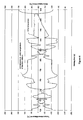
Figure 2 shows modeling calculations by the inventors on the CO emission of the diesel engine during the test for different platinum loadings of the diesel oxidation catalyst. The emission values were calculated for exhaust gas temperatures decreased or increased linearly relative to the reference case. The emission values for the abscissa value of 1.00 indicate the CO emission of the diesel engine at the original exhaust gas temperature corresponding to the reference curve offigure 1 for different platinum loadings. For abscissa values deviating from this, an exhaust gas temperature of the diesel engine increased or reduced linearly relative to the reference curve was assumed. In the case of the abscissa values 0.85 and 1.15, these temperature curves are shown infigure 1 , curve a) for an exhaust gas temperature reduced linearly by 15% and curve b) for an exhaust gas temperature increased linearly by 15%. - It can be seen from
figure 2 that the emission of carbon monoxide during the test at a given platinum loading can be decreased by increasing the exhaust gas temperature. Thus, an aging-induced deterioration in the emission values can be compensated by increasing the exhaust gas temperature. - It is known that the exhaust gas temperatures of a diesel engine can be increased by means of various measures. For the purposes of the invention, the exhaust gas temperature of the engine can be increased either immediately after the cold start or after some time delay. In the first case, preference is given to selecting measures which have only a small influence on the emission behavior of the engine so as to prevent excessive emission of pollutants during the cold start phase. In the latter case, it is also possible to choose measures which lead to somewhat higher emission values, since pollutants are reliably converted into nonpolluting substances by the method of the invention.
- Possible measures for increasing the exhaust gas temperature for the purposes of the method of the invention are, for example:
- Choking the air drawn in, which results in the amount of exhaust gas being reduced at the same power; this leads to a higher temperature
- Increasing the exhaust gas temperature by post-injection, possibly in only one cylinder
- Shifting the combustion peak to "later"; a 1° shift in the combustion peak results in a temperature increase of about 10 K
- Increasing the exhaust gas backpressure
- Altering the gearing ratio of the gearbox
- Switching off the charge cooling
- The above measures for increasing the temperature of the exhaust gas result in a slight increase in fuel consumption. To keep this additional consumption as small as possible, these measures are preferably employed only when the exhaust gas temperature drops below a prescribed minimum temperature. When the diesel engine is operated at high load, the exhaust gas temperature is generally sufficiently high for even an aged catalyst to ensure satisfactory conversion of pollutants.
- Among the above-described measures for increasing the temperature of the exhaust gas, choking the engine is very effective.
Figure 3 shows this by way of example for a heavy duty vehicle engine. The temperature curve denoted by "production model" indicates the exhaust gas temperature upstream of a particle filter for a particular driving cycle. The exhaust gas temperature during this same driving cycle can be increased by about 100°C by choking the engine (curve "modified engine"). This causes an additional fuel consumption of about 10%. However, the method of the invention generally requires a temperature increase of only 20 K or less to compensate for the aging of the catalyst. The additional fuel consumption due to the method will therefore be correspondingly lower. - The aging-induced decrease in the catalytic activity can be determined in various ways.
- In the simplest case, an average aging behavior for a series of catalysts can be measured beforehand as a function of the time of operation. To implement the method, it is then possible, for example, to enter the necessary modifications to the operating parameters which ensure a sufficient increase in the exhaust gas temperature for the respective aging state in the engine control system of the diesel engine as a function of the time of operation.
- However, it is more advantageous to determine the aging state of the catalyst directly. Both continuous and discontinuous methods of determination are suitable for this purpose. For example, the aging state can be determined by continuously measuring the pollutant conversion by means of a directly measuring gas sensor system and fitting the data to a catalyst model entered in the engine control system. Similarly to the previous case, the necessary modifications to the operating parameters which ensure a sufficient increase in the exhaust gas temperature for the respective aging state can be entered in the engine control system as a function of the aging state determined.
- The gas sensor system for determining the pollutant conversion can, for example, comprise a sensor upstream of the catalyst and a sensor downstream of the catalyst for the pollutant concerned (CO, HC or NO). The sensor upstream of the catalyst can be omitted if the pollutant concentrations in the exhaust gas for any operating point of the engine have previously been entered in the form of performance characteristics in the engine control system.
- As indicated above, the aging state of the catalyst can also be determined discontinuously, i.e. after a particular distance covered or a particular number of hours of operation. For this purpose, for example, the heat evolved over the catalyst on post-injection of a defined amount of hydrocarbons can be measured. The fresh catalyst burns the additional hydrocarbons better than the aged catalyst and therefore leads to a greater increase in the temperature of the exhaust gas as a result of this process.
- The necessary changes to the operating parameters of the engine can be determined directly as follows: the heat evolved in the combustion of a given amount of hydrocarbons over the catalyst is firstly measured and compared with the heat evolved over the fresh catalyst at this operating point. In the case of a reduced amount of heat evolved compared to the fresh catalyst, the exhaust gas temperature of the engine prevailing at this operating point is increased without altering the torque by engine measures until the newly measured heat evolved over the aged catalyst corresponds to the heat evolved over the fresh catalyst. From this it is possible to determine the factor by which the exhaust gas temperature has to be increased to compensate for the aging-induced decrease in performance of the catalyst. In this case too, the necessary modifications to the process parameters which ensure a sufficient increase in the exhaust gas temperature for the respective aging state at all other operating points can be entered in the engine control system as a function of the factor determined.
- If the diesel engine is also equipped with a particle filter, the above-described determination of the aging state via the heat evolved on combustion of a defined amount of hydrocarbons can also be combined particularly advantageously with the regeneration function for the particle filter. To regenerate the particle filter, the exhaust gas temperature at the particle filter is from time to time increased to the ignition temperature of the soot in order to burn the latter. This is usually achieved by post-injection of hydrocarbons and combustion of these over the oxidation catalyst. The heat evolved in this procedure can at the same time be utilized for determining the aging state of the oxidation catalyst.
-
Figures 4 to 6 illustrate the determination of the aging state by means of the evolution of heat with the aid of modeling calculations on the above-described drive system comprising a 1.41 diesel engine provided with a 2.41 honeycomb catalyst. The modelling calculations were carried out for an arbitrary section of the NEDC test. It was assumed that post-injection increases the HC concentration in the exhaust gas to 10 000 ppm in the driving time interval from 710 to 830 seconds. -
Figure 4 shows the calculated temperature curves for the exhaust gas temperature at the entrance to the catalyst (curve "entry temperature") and for the temperature difference between the exit temperature of the exhaust gas on leaving the catalyst and the entry temperature. A positive temperature difference indicates an exothermic reaction over the catalyst. The calculation of the temperature difference infigure 4 was carried out for a fresh catalyst without HC post-injection. -
Figure 5 shows the comparison of the evolution of heat with post-injection of hydrocarbons for the fresh catalyst and an aged catalyst. It can be seen that the evolution of heat over the aged catalyst is significantly lower than in the case of the fresh catalyst. -
Figure 6 shows the comparison of the evolution of heat over the fresh catalyst with post-injection with the evolution of heat over the aged catalyst with post-injection and a simultaneous, linear temperature increase by 10%. As can be seen fromfigure 6 , a linear temperature increase of 10% in the calculated example is sufficient to increase the reduced catalytic activity of the aged catalyst almost to the level of the fresh catalyst.
Claims (1)
- A method of operating a drive system comprising a diesel engine and an exhaust gas purification unit containing a catalyst, where the engine emits an exhaust gas having an exhaust gas temperature and the catalyst has a catalytic activity for the purification of the exhaust gas, wherein an aging-induced decrease in the catalytic activity of the catalyst is compensated at least part of the time by increasing the exhaust gas temperature of the engine,
characterized in that the aging-induced decrease in the catalytic activity of the catalyst is compensated by increasing the exhaust gas temperature of the engine by a factor for all operating points of the engine wherein said factor is determined as follows:(a) the heat evolved in the combustion of a particular amount of hydrocarbons over the catalyst at a particular operating point of the internal combustion engine is measured after a defined number of hours of operation,(b) the heat evolved is compared with the heat evolved over a fresh catalyst at this operating point,(c) in the case of a reduced evolution of heat relative to the fresh catalyst the exhaust gas temperature of the engine prevailing at this operating point is increased by engine measures without changing the torque until the measured quantity of heat evolved over the aged catalyst corresponds to the heat evolved over the fresh catalyst,(d) determining said factor as the ratio of the exhaust gas temperature of the engine after temperature increase in step (c) relative to the exhaust gas temperature before temperature increase.
Applications Claiming Priority (2)
| Application Number | Priority Date | Filing Date | Title |
|---|---|---|---|
| DE10323247A DE10323247A1 (en) | 2003-05-22 | 2003-05-22 | Method for operating a drive system from a diesel engine with a diesel oxidation catalyst for exhaust gas purification |
| PCT/EP2004/005360 WO2004103528A1 (en) | 2003-05-22 | 2004-05-18 | Method of operating a system comprising a diesel engine and a catalyst for exhaust gas purification |
Publications (2)
| Publication Number | Publication Date |
|---|---|
| EP1633461A1 EP1633461A1 (en) | 2006-03-15 |
| EP1633461B1 true EP1633461B1 (en) | 2010-05-05 |
Family
ID=33441174
Family Applications (1)
| Application Number | Title | Priority Date | Filing Date |
|---|---|---|---|
| EP04739251A Active EP1633461B1 (en) | 2003-05-22 | 2004-05-18 | Method of operating a system comprising a diesel engine and a catalyst for exhaust gas purification |
Country Status (6)
| Country | Link |
|---|---|
| US (1) | US7310940B2 (en) |
| EP (1) | EP1633461B1 (en) |
| JP (1) | JP2007502388A (en) |
| AT (1) | ATE466645T1 (en) |
| DE (2) | DE10323247A1 (en) |
| WO (1) | WO2004103528A1 (en) |
Families Citing this family (11)
| Publication number | Priority date | Publication date | Assignee | Title |
|---|---|---|---|---|
| JP4428361B2 (en) * | 2006-05-24 | 2010-03-10 | トヨタ自動車株式会社 | Exhaust gas purification system for internal combustion engine |
| JP4665924B2 (en) * | 2007-03-16 | 2011-04-06 | トヨタ自動車株式会社 | Exhaust gas purification system for internal combustion engine |
| DE102008057814A1 (en) * | 2008-11-18 | 2010-05-27 | Iav Gmbh Ingenieurgesellschaft Auto Und Verkehr | Method for evaluation and adjustment of conversion behavior of catalyst in waste gas system of motor vehicle, involves determining operating conditions of internal combustion engine and waste gas system by controller |
| US8505277B2 (en) * | 2009-08-06 | 2013-08-13 | GM Global Technology Operations LLC | System and methods for controlling selective catalytic reduction systems |
| DE102010037431A1 (en) * | 2010-09-09 | 2012-03-15 | Ford Global Technologies, Llc. | Method for adjusting an exothermic reaction in the exhaust system of a motor vehicle |
| US20120222399A1 (en) * | 2011-03-03 | 2012-09-06 | GM Global Technology Operations LLC | Oxidation catalyst burn threshold adjustment to avoid quenching |
| US20130283767A1 (en) * | 2012-04-30 | 2013-10-31 | GM Global Technology Operations LLC | Oxidation catalyst monitoring |
| FR2993923B1 (en) * | 2012-07-26 | 2017-09-01 | Peugeot Citroen Automobiles Sa | EXHAUST GAS POST-TREATMENT SYSTEM |
| SE539296C2 (en) * | 2013-04-25 | 2017-06-20 | Scania Cv Ab | Method and system for controlling an internal combustion engine by controlling the combustion in an internal combustion chamber during the current combustion cycle |
| DE102014100896A1 (en) * | 2014-01-27 | 2015-07-30 | Thyssenkrupp Ag | Process for the heat treatment of a material stream and for the purification of resulting exhaust gases |
| CN114658541B (en) * | 2022-03-18 | 2023-06-23 | 东风汽车集团股份有限公司 | Temperature discharge determining method and device and storage medium |
Family Cites Families (14)
| Publication number | Priority date | Publication date | Assignee | Title |
|---|---|---|---|---|
| DE3822415A1 (en) * | 1987-11-12 | 1989-05-24 | Man Technologie Gmbh | METHOD AND DEVICE FOR REGULATING THE COMBUSTION AIR CONDITION IN COMBUSTION ENGINES |
| US5201802A (en) | 1991-02-04 | 1993-04-13 | Toyota Jidosha Kabushiki Kaisha | Exhaust gas purification system for an internal combustion engine |
| JP2884798B2 (en) * | 1991-02-04 | 1999-04-19 | トヨタ自動車株式会社 | Exhaust gas purification device for internal combustion engine |
| JP2869903B2 (en) * | 1991-03-26 | 1999-03-10 | 本田技研工業株式会社 | Catalyst temperature control device for internal combustion engine |
| US5261230A (en) * | 1991-08-02 | 1993-11-16 | Toyota Jidosha Kabushiki Kaisha | Device for controlling heating of catalyst for purifying exhaust gas |
| US5325664A (en) * | 1991-10-18 | 1994-07-05 | Honda Giken Kogyo Kabushiki Kaisha | System for determining deterioration of catalysts of internal combustion engines |
| DE4211092A1 (en) * | 1992-04-03 | 1993-10-07 | Bosch Gmbh Robert | Method and device for assessing the functionality of a catalytic converter |
| JP3157061B2 (en) * | 1993-04-26 | 2001-04-16 | 株式会社日立製作所 | Catalyst deterioration diagnosis system |
| JP3266699B2 (en) * | 1993-06-22 | 2002-03-18 | 株式会社日立製作所 | Catalyst evaluation method, catalyst efficiency control method, and NOx purification catalyst evaluation apparatus |
| US5857163A (en) * | 1995-12-12 | 1999-01-05 | General Motors Corporation | Adaptive engine control responsive to catalyst deterioration estimation |
| DE19963932A1 (en) * | 1999-12-31 | 2001-07-12 | Bosch Gmbh Robert | Method for operating an internal combustion engine, in particular a motor vehicle |
| JP3613670B2 (en) * | 2000-02-08 | 2005-01-26 | トヨタ自動車株式会社 | Exhaust gas purification device for internal combustion engine |
| US6993899B2 (en) * | 2001-06-20 | 2006-02-07 | Ford Global Technologies, Llc | System and method for controlling catalyst storage capacity |
| DE10148128A1 (en) * | 2001-09-28 | 2003-04-30 | Volkswagen Ag | Method and device for reducing pollutant emissions from an internal combustion engine |
-
2003
- 2003-05-22 DE DE10323247A patent/DE10323247A1/en not_active Withdrawn
-
2004
- 2004-05-18 AT AT04739251T patent/ATE466645T1/en not_active IP Right Cessation
- 2004-05-18 DE DE602004027035T patent/DE602004027035D1/en active Active
- 2004-05-18 WO PCT/EP2004/005360 patent/WO2004103528A1/en active Application Filing
- 2004-05-18 US US10/558,142 patent/US7310940B2/en not_active Expired - Fee Related
- 2004-05-18 JP JP2006529866A patent/JP2007502388A/en active Pending
- 2004-05-18 EP EP04739251A patent/EP1633461B1/en active Active
Also Published As
| Publication number | Publication date |
|---|---|
| EP1633461A1 (en) | 2006-03-15 |
| WO2004103528A1 (en) | 2004-12-02 |
| DE10323247A1 (en) | 2004-12-09 |
| DE602004027035D1 (en) | 2010-06-17 |
| JP2007502388A (en) | 2007-02-08 |
| ATE466645T1 (en) | 2010-05-15 |
| US7310940B2 (en) | 2007-12-25 |
| US20070006570A1 (en) | 2007-01-11 |
Similar Documents
| Publication | Publication Date | Title |
|---|---|---|
| Nakatani et al. | Simultaneous PM and NOx reduction system for diesel engines | |
| CA2341065C (en) | Process for checking the operatability of an exhaust gas purification catalyst | |
| US9328682B2 (en) | Regulating strategy for a catalytic converter concept for exhaust-gas aftertreatment having a plurality of nitrogen oxide storage catalytic converters | |
| US6502386B1 (en) | Catalyst monitoring in a diesel engine | |
| US6021638A (en) | Engine management strategy to improve the ability of a catalyst to withstand severe operating enviroments | |
| EP1633461B1 (en) | Method of operating a system comprising a diesel engine and a catalyst for exhaust gas purification | |
| Pauly et al. | Cost and fuel economy driven aftertreatment solutions-for lean GDI | |
| US10047653B2 (en) | Regeneration method for exhaust-gas aftertreatment systems | |
| JP2009513868A (en) | Device for treating nitric oxide in automobile exhaust gas | |
| JP2008544149A (en) | Method and apparatus for operating a particle collector | |
| US8857152B2 (en) | System and method for unloading hydrocarbon emissions from an exhaust after-treatment device | |
| US10968805B2 (en) | Motor vehicle and a method for operating a motor vehicle | |
| König et al. | Current tasks and challenges for exhaust aftertreatment research. A viewpoint from the automotive industry | |
| Johnson | Diesel emission control in review | |
| Johnson et al. | Review of deNOx technology for mobile applications | |
| JP3613083B2 (en) | Exhaust purification control device | |
| Webb et al. | Achieving Tier 2 Bin 5 Emission Levels with a Medium Duty Diesel Pick-Up and a NO x Adsorber, Diesel Particulate Filter Emissions System—NO x Adsorber Management | |
| Toorisaka et al. | DPR developed for extremely low PM emissions in production commercial vehicles | |
| Özyalcin et al. | Exhaust gas aftertreatment to minimize NOX emissions from hydrogen-fueled internal combustion engines | |
| JP2007501356A (en) | Method for purifying diesel engine exhaust gas with diesel oxidation catalyst | |
| CN113027571B (en) | Method and drive device for reactivating an exhaust gas aftertreatment component | |
| US20070144148A1 (en) | System for assisting the regeneration of depollution means included in a motor vehicle exhaust line | |
| Choung et al. | Smart engine control strategy for the fuel efficiency improvement via understanding the unique behavior of twc | |
| Tayal | Light off temperature based approach to determine diesel oxidation catalyst effectiveness level and the corresponding outlet NO and NO 2 characteristics | |
| Matsumoto et al. | Advanced emission control technologies for PM reduction in heavy-duty applications |
Legal Events
| Date | Code | Title | Description |
|---|---|---|---|
| PUAI | Public reference made under article 153(3) epc to a published international application that has entered the european phase |
Free format text: ORIGINAL CODE: 0009012 |
|
| 17P | Request for examination filed |
Effective date: 20051123 |
|
| AK | Designated contracting states |
Kind code of ref document: A1 Designated state(s): AT BE BG CH CY CZ DE DK EE ES FI FR GB GR HU IE IT LI LU MC NL PL PT RO SE SI SK TR |
|
| DAX | Request for extension of the european patent (deleted) | ||
| 17Q | First examination report despatched |
Effective date: 20061228 |
|
| GRAP | Despatch of communication of intention to grant a patent |
Free format text: ORIGINAL CODE: EPIDOSNIGR1 |
|
| GRAJ | Information related to disapproval of communication of intention to grant by the applicant or resumption of examination proceedings by the epo deleted |
Free format text: ORIGINAL CODE: EPIDOSDIGR1 |
|
| GRAP | Despatch of communication of intention to grant a patent |
Free format text: ORIGINAL CODE: EPIDOSNIGR1 |
|
| GRAS | Grant fee paid |
Free format text: ORIGINAL CODE: EPIDOSNIGR3 |
|
| GRAA | (expected) grant |
Free format text: ORIGINAL CODE: 0009210 |
|
| AK | Designated contracting states |
Kind code of ref document: B1 Designated state(s): AT BE BG CH CY CZ DE DK EE ES FI FR GB GR HU IE IT LI LU MC NL PL PT RO SE SI SK TR |
|
| REG | Reference to a national code |
Ref country code: GB Ref legal event code: FG4D |
|
| REG | Reference to a national code |
Ref country code: CH Ref legal event code: EP |
|
| REG | Reference to a national code |
Ref country code: IE Ref legal event code: FG4D |
|
| REF | Corresponds to: |
Ref document number: 602004027035 Country of ref document: DE Date of ref document: 20100617 Kind code of ref document: P |
|
| REG | Reference to a national code |
Ref country code: NL Ref legal event code: VDEP Effective date: 20100505 |
|
| PG25 | Lapsed in a contracting state [announced via postgrant information from national office to epo] |
Ref country code: NL Free format text: LAPSE BECAUSE OF FAILURE TO SUBMIT A TRANSLATION OF THE DESCRIPTION OR TO PAY THE FEE WITHIN THE PRESCRIBED TIME-LIMIT Effective date: 20100505 Ref country code: SE Free format text: LAPSE BECAUSE OF FAILURE TO SUBMIT A TRANSLATION OF THE DESCRIPTION OR TO PAY THE FEE WITHIN THE PRESCRIBED TIME-LIMIT Effective date: 20100505 Ref country code: ES Free format text: LAPSE BECAUSE OF FAILURE TO SUBMIT A TRANSLATION OF THE DESCRIPTION OR TO PAY THE FEE WITHIN THE PRESCRIBED TIME-LIMIT Effective date: 20100816 |
|
| PG25 | Lapsed in a contracting state [announced via postgrant information from national office to epo] |
Ref country code: SI Free format text: LAPSE BECAUSE OF FAILURE TO SUBMIT A TRANSLATION OF THE DESCRIPTION OR TO PAY THE FEE WITHIN THE PRESCRIBED TIME-LIMIT Effective date: 20100505 Ref country code: FI Free format text: LAPSE BECAUSE OF FAILURE TO SUBMIT A TRANSLATION OF THE DESCRIPTION OR TO PAY THE FEE WITHIN THE PRESCRIBED TIME-LIMIT Effective date: 20100505 Ref country code: AT Free format text: LAPSE BECAUSE OF FAILURE TO SUBMIT A TRANSLATION OF THE DESCRIPTION OR TO PAY THE FEE WITHIN THE PRESCRIBED TIME-LIMIT Effective date: 20100505 |
|
| PG25 | Lapsed in a contracting state [announced via postgrant information from national office to epo] |
Ref country code: PL Free format text: LAPSE BECAUSE OF FAILURE TO SUBMIT A TRANSLATION OF THE DESCRIPTION OR TO PAY THE FEE WITHIN THE PRESCRIBED TIME-LIMIT Effective date: 20100505 Ref country code: GR Free format text: LAPSE BECAUSE OF FAILURE TO SUBMIT A TRANSLATION OF THE DESCRIPTION OR TO PAY THE FEE WITHIN THE PRESCRIBED TIME-LIMIT Effective date: 20100806 Ref country code: CY Free format text: LAPSE BECAUSE OF FAILURE TO SUBMIT A TRANSLATION OF THE DESCRIPTION OR TO PAY THE FEE WITHIN THE PRESCRIBED TIME-LIMIT Effective date: 20100505 Ref country code: MC Free format text: LAPSE BECAUSE OF NON-PAYMENT OF DUE FEES Effective date: 20100531 |
|
| REG | Reference to a national code |
Ref country code: CH Ref legal event code: PL |
|
| PG25 | Lapsed in a contracting state [announced via postgrant information from national office to epo] |
Ref country code: DK Free format text: LAPSE BECAUSE OF FAILURE TO SUBMIT A TRANSLATION OF THE DESCRIPTION OR TO PAY THE FEE WITHIN THE PRESCRIBED TIME-LIMIT Effective date: 20100505 Ref country code: PT Free format text: LAPSE BECAUSE OF FAILURE TO SUBMIT A TRANSLATION OF THE DESCRIPTION OR TO PAY THE FEE WITHIN THE PRESCRIBED TIME-LIMIT Effective date: 20100906 Ref country code: EE Free format text: LAPSE BECAUSE OF FAILURE TO SUBMIT A TRANSLATION OF THE DESCRIPTION OR TO PAY THE FEE WITHIN THE PRESCRIBED TIME-LIMIT Effective date: 20100505 |
|
| PG25 | Lapsed in a contracting state [announced via postgrant information from national office to epo] |
Ref country code: CZ Free format text: LAPSE BECAUSE OF FAILURE TO SUBMIT A TRANSLATION OF THE DESCRIPTION OR TO PAY THE FEE WITHIN THE PRESCRIBED TIME-LIMIT Effective date: 20100505 Ref country code: SK Free format text: LAPSE BECAUSE OF FAILURE TO SUBMIT A TRANSLATION OF THE DESCRIPTION OR TO PAY THE FEE WITHIN THE PRESCRIBED TIME-LIMIT Effective date: 20100505 Ref country code: LI Free format text: LAPSE BECAUSE OF NON-PAYMENT OF DUE FEES Effective date: 20100531 Ref country code: RO Free format text: LAPSE BECAUSE OF FAILURE TO SUBMIT A TRANSLATION OF THE DESCRIPTION OR TO PAY THE FEE WITHIN THE PRESCRIBED TIME-LIMIT Effective date: 20100505 Ref country code: BE Free format text: LAPSE BECAUSE OF FAILURE TO SUBMIT A TRANSLATION OF THE DESCRIPTION OR TO PAY THE FEE WITHIN THE PRESCRIBED TIME-LIMIT Effective date: 20100505 Ref country code: CH Free format text: LAPSE BECAUSE OF NON-PAYMENT OF DUE FEES Effective date: 20100531 |
|
| PLBE | No opposition filed within time limit |
Free format text: ORIGINAL CODE: 0009261 |
|
| STAA | Information on the status of an ep patent application or granted ep patent |
Free format text: STATUS: NO OPPOSITION FILED WITHIN TIME LIMIT |
|
| 26N | No opposition filed |
Effective date: 20110208 |
|
| PG25 | Lapsed in a contracting state [announced via postgrant information from national office to epo] |
Ref country code: IE Free format text: LAPSE BECAUSE OF NON-PAYMENT OF DUE FEES Effective date: 20100518 |
|
| REG | Reference to a national code |
Ref country code: DE Ref legal event code: R097 Ref document number: 602004027035 Country of ref document: DE Effective date: 20110207 |
|
| PG25 | Lapsed in a contracting state [announced via postgrant information from national office to epo] |
Ref country code: LU Free format text: LAPSE BECAUSE OF NON-PAYMENT OF DUE FEES Effective date: 20100518 Ref country code: HU Free format text: LAPSE BECAUSE OF FAILURE TO SUBMIT A TRANSLATION OF THE DESCRIPTION OR TO PAY THE FEE WITHIN THE PRESCRIBED TIME-LIMIT Effective date: 20101106 Ref country code: BG Free format text: LAPSE BECAUSE OF FAILURE TO SUBMIT A TRANSLATION OF THE DESCRIPTION OR TO PAY THE FEE WITHIN THE PRESCRIBED TIME-LIMIT Effective date: 20100505 |
|
| PG25 | Lapsed in a contracting state [announced via postgrant information from national office to epo] |
Ref country code: TR Free format text: LAPSE BECAUSE OF FAILURE TO SUBMIT A TRANSLATION OF THE DESCRIPTION OR TO PAY THE FEE WITHIN THE PRESCRIBED TIME-LIMIT Effective date: 20100505 |
|
| PG25 | Lapsed in a contracting state [announced via postgrant information from national office to epo] |
Ref country code: BG Free format text: LAPSE BECAUSE OF FAILURE TO SUBMIT A TRANSLATION OF THE DESCRIPTION OR TO PAY THE FEE WITHIN THE PRESCRIBED TIME-LIMIT Effective date: 20100805 |
|
| REG | Reference to a national code |
Ref country code: FR Ref legal event code: PLFP Year of fee payment: 13 |
|
| REG | Reference to a national code |
Ref country code: FR Ref legal event code: PLFP Year of fee payment: 14 |
|
| REG | Reference to a national code |
Ref country code: FR Ref legal event code: PLFP Year of fee payment: 15 |
|
| PGFP | Annual fee paid to national office [announced via postgrant information from national office to epo] |
Ref country code: GB Payment date: 20180329 Year of fee payment: 15 |
|
| PGFP | Annual fee paid to national office [announced via postgrant information from national office to epo] |
Ref country code: IT Payment date: 20180522 Year of fee payment: 15 Ref country code: FR Payment date: 20180411 Year of fee payment: 15 |
|
| REG | Reference to a national code |
Ref country code: DE Ref legal event code: R084 Ref document number: 602004027035 Country of ref document: DE |
|
| GBPC | Gb: european patent ceased through non-payment of renewal fee |
Effective date: 20190518 |
|
| PG25 | Lapsed in a contracting state [announced via postgrant information from national office to epo] |
Ref country code: IT Free format text: LAPSE BECAUSE OF NON-PAYMENT OF DUE FEES Effective date: 20190518 Ref country code: GB Free format text: LAPSE BECAUSE OF NON-PAYMENT OF DUE FEES Effective date: 20190518 |
|
| PG25 | Lapsed in a contracting state [announced via postgrant information from national office to epo] |
Ref country code: FR Free format text: LAPSE BECAUSE OF NON-PAYMENT OF DUE FEES Effective date: 20190531 |
|
| P01 | Opt-out of the competence of the unified patent court (upc) registered |
Effective date: 20230602 |
|
| PGFP | Annual fee paid to national office [announced via postgrant information from national office to epo] |
Ref country code: DE Payment date: 20230321 Year of fee payment: 20 |