EP1632769A1 - Apparatus and method for detecting scattering material by terahertz wave transmission while eliminating unscattered component transmitted in a rectilinear manner - Google Patents
Apparatus and method for detecting scattering material by terahertz wave transmission while eliminating unscattered component transmitted in a rectilinear manner Download PDFInfo
- Publication number
- EP1632769A1 EP1632769A1 EP20050018527 EP05018527A EP1632769A1 EP 1632769 A1 EP1632769 A1 EP 1632769A1 EP 20050018527 EP20050018527 EP 20050018527 EP 05018527 A EP05018527 A EP 05018527A EP 1632769 A1 EP1632769 A1 EP 1632769A1
- Authority
- EP
- European Patent Office
- Prior art keywords
- terahertz wave
- wave
- inspected
- scattered
- terahertz
- Prior art date
- Legal status (The legal status is an assumption and is not a legal conclusion. Google has not performed a legal analysis and makes no representation as to the accuracy of the status listed.)
- Granted
Links
Images



Classifications
-
- G—PHYSICS
- G01—MEASURING; TESTING
- G01V—GEOPHYSICS; GRAVITATIONAL MEASUREMENTS; DETECTING MASSES OR OBJECTS; TAGS
- G01V8/00—Prospecting or detecting by optical means
- G01V8/005—Prospecting or detecting by optical means operating with millimetre waves, e.g. measuring the black losey radiation
-
- G—PHYSICS
- G01—MEASURING; TESTING
- G01N—INVESTIGATING OR ANALYSING MATERIALS BY DETERMINING THEIR CHEMICAL OR PHYSICAL PROPERTIES
- G01N21/00—Investigating or analysing materials by the use of optical means, i.e. using sub-millimetre waves, infrared, visible or ultraviolet light
- G01N21/17—Systems in which incident light is modified in accordance with the properties of the material investigated
- G01N21/25—Colour; Spectral properties, i.e. comparison of effect of material on the light at two or more different wavelengths or wavelength bands
- G01N21/31—Investigating relative effect of material at wavelengths characteristic of specific elements or molecules, e.g. atomic absorption spectrometry
- G01N21/35—Investigating relative effect of material at wavelengths characteristic of specific elements or molecules, e.g. atomic absorption spectrometry using infrared light
- G01N21/3581—Investigating relative effect of material at wavelengths characteristic of specific elements or molecules, e.g. atomic absorption spectrometry using infrared light using far infrared light; using Terahertz radiation
-
- G—PHYSICS
- G01—MEASURING; TESTING
- G01N—INVESTIGATING OR ANALYSING MATERIALS BY DETERMINING THEIR CHEMICAL OR PHYSICAL PROPERTIES
- G01N21/00—Investigating or analysing materials by the use of optical means, i.e. using sub-millimetre waves, infrared, visible or ultraviolet light
- G01N21/17—Systems in which incident light is modified in accordance with the properties of the material investigated
- G01N21/25—Colour; Spectral properties, i.e. comparison of effect of material on the light at two or more different wavelengths or wavelength bands
- G01N21/31—Investigating relative effect of material at wavelengths characteristic of specific elements or molecules, e.g. atomic absorption spectrometry
- G01N21/35—Investigating relative effect of material at wavelengths characteristic of specific elements or molecules, e.g. atomic absorption spectrometry using infrared light
- G01N21/3563—Investigating relative effect of material at wavelengths characteristic of specific elements or molecules, e.g. atomic absorption spectrometry using infrared light for analysing solids; Preparation of samples therefor
Definitions
- the present invention relates to an apparatus and method for detecting scattered material such as powder or foam contained in an envelope, a capsule, a container or the like by use of terahertz waves without unsealing the envelope or the like.
- terahertz waves electromagnetic waves having frequencies around 1 THz, that is, far-infrared rays and sub-millimeter waves in this frequency region.
- the terahertz wave is positioned in a boundary between a light wave and a radio wave, and has characteristics of both of the light and radio waves.
- the terahertz wave is the shortest wavelength band having material transmitting properties of the radio wave as well as the longest wavelength having straight moving properties of the light wave. More specifically, the terahertz wave is similar to the radio wave in that the wave can pass through various materials. Since the terahertz wave has a short wavelength (around 1 millimeter to 30 micron meters), the wave can obtain the highest spatial resolution in a radio wave band. The terahertz wave is similar to the light wave in that the wave can be treated by lens or mirrors.
- the apparatus comprises: means 51 for holding powder; irradiation means 52a, 52b, 52c for irradiating the powder with terahertz electromagnetic waves; receiving means 53a, 53b, 53c for receiving the terahertz electromagnetic waves which have passed through the powder to convert the waves into electric signals; means 54 for acquiring from outputs of the receiving means a difference of propagation times or amplitudes between positions of the powder where the terahertz electromagnetic waves pass; and image processing means 55 for processing an image to display the characteristics of the powder in a display based on the difference.
- the apparatus measures the characteristics of the powder.
- a transmittance, a refractive index, a filling ratio and the like of the powder are measured by this means.
- terahertz waves 64a, 64b on two different wavelengths are generated in a frequency range of about 0.5 to 3 THz, a material 65 to be inspected is irradiated with the terahertz waves on two wavelengths 64a, 64b to measure the transmittances, and presence of a target having dependence of the wavelength on absorption of the terahertz wave is detected from a difference between the transmittances.
- the dependence of DNA of salmon or the like on the wavelength is measured by this means.
- an object of the present invention is to provide a scattered material detection apparatus and method capable of detecting a scattered material such as powder or foam contained in an envelope, a capsule, a container or the like in a non-destructive manner without unsealing the envelope or the like by use of a terahertz wave.
- the terahertz wave has a high transmitting property through the envelope, a plastic container or the like, and usually rectilinearly passes therethrough as such.
- the terahertz wave is usually intensely scattered because of its short wavelength. Therefore, when a rectilinear wave and a scattered wave of terahertz light are measured separately from each other, it is possible to detect the presence of the scattered material such as the powder or the foam in the envelope or the plastic container.
- the present invention is based on such inventive finding.
- a scattered material detection apparatus using a terahertz wave comprising: a terahertz wave generation device which generates the terahertz wave; a terahertz wave irradiation device which irradiates an object to be inspected with the terahertz wave; and a scattering intensity detection device for cutting a rectilinear wave of the terahertz wave which has passed through the object to be inspected and for detecting an intensity of a scattered wave.
- the terahertz wave irradiation device comprises: a lens which converts the generated terahertz wave into parallel light; and an iris diaphragm which limits a sectional shape of the parallel light to be smaller than that of the object to be inspected to irradiate the object with the light.
- the scattering intensity detection device comprises: a confocal optical system for interrupting the terahertz wave which has rectilinearly passed through the object to be inspected midway and for focusing the terahertz wave scattered by the object to be inspected in a predetermined position; and a scattering intensity detection unit which detects the intensity of the terahertz wave in the focal position.
- the confocal optical system comprises: first and second off-axis parabolic mirrors which face each other; and a shielding member which is positioned between the two off-axis parabolic mirrors and which cuts the rectilinear wave of the terahertz wave and which transmits the scattered wave.
- the first off-axis parabolic mirror has an incidence-side focus and a reflection-side focus along an axial line of the terahertz wave
- the object to be inspected is positioned in the incidence-side focus of the first off-axis parabolic mirror or its vicinity
- the shielding member is positioned in the reflection-side focus of the first off-axis parabolic mirror or its vicinity.
- the confocal optical system comprises: first and second convex lenses which face each other; and a shielding member which is positioned between two convex lenses and which cuts the rectilinear wave of the terahertz wave and which transmits the scattered wave.
- the first convex lens has an incidence-side focus and an outlet-side focus along an axial line of the terahertz wave
- the object to be inspected is positioned in the incidence-side focus of the first convex lens or its vicinity
- the shielding member is positioned in the outlet-side focus of the first convex lens or its vicinity.
- a scattered material detection method using a terahertz wave comprising: a terahertz wave generating step of generating the terahertz wave; a terahertz wave irradiating step of irradiating an object to be inspected with the terahertz wave; and a scattering intensity detecting step of cutting a rectilinear wave of the terahertz wave which has passed through the object to be inspected and detecting an intensity of a scattered wave.
- the terahertz wave generated in the terahertz wave generating step is converted into parallel light, and a sectional shape of the parallel light is limited to be smaller than that of the object to be inspected to irradiate the object with the light.
- the terahertz wave which has rectilinearly passed through the object to be inspected is interrupted midway, the terahertz wave scattered by the object to be inspected is focused in a predetermined position, and the intensity of the terahertz wave in the focal position is detected.
- the apparatus and the method of the present invention superior effects are produced.
- the rectilinear wave of the terahertz wave which has passed through the object to be inspected can be cut, and the intensity of the scattered wave can be detected. Therefore, a scattered material such as powder or foam contained in an envelope, a capsule, a container or the like can be detected in a non-destructive manner without unsealing the envelope or the like.
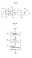
- FIG. 3 is a configuration diagram of a first embodiment of a scattered material detection apparatus of the present invention.
- a scattered material detection apparatus 10 of the present invention is provided with a terahertz wave generation device 12, a terahertz wave irradiation device 14, and a scattering intensity detection device 20.
- the terahertz wave generation device 12 generates a terahertz wave 2.
- the terahertz wave 2 has a constant wavelength in a range of around 1 millimeter to 30 micron meter, and is preferably a continuous or pulse wave having a certain output.
- a generation source of the generated terahertz wave may be a spot light source, a linear light source, or a parallel light source.
- the terahertz wave irradiation device 14 irradiates an object 1 to be inspected with the terahertz wave 2.
- the terahertz wave irradiation device 14 comprises: a lens 15 which converts the generated terahertz wave 2 into parallel light; and an iris diaphragm 16 which limits a sectional shape of the parallel light to be smaller than that of the object 1 to be inspected to irradiate the object with the light.
- the generation source of the terahertz wave 2 is the linear light source which is parallel to a drawing sheet surface, and the lens 15 is a cylindrical lens which extends in parallel with the sheet surface.
- the generation source of the terahertz wave 2 is positioned in a linear focal position of the cylindrical lens 15, and the wave is converted into the parallel light whose sectional shape is rectangular by means of the cylindrical lens 15.
- the iris diaphragm 16 has a rectangular aperture which is smaller than the object 1 to be inspected, the output of the terahertz wave 2 with which the object 1 to be inspected is irradiated is kept to be constant, and the object 1 to be inspected is irradiated with a total quantity of output.
- the lens 15 is not limited to this constitution, and a usual convex lens system may be used with respect to the spot light source.
- the iris diaphragm 16 is not limited to this constitution, and may be a circular or rectangular variable diaphragm.
- the scattering intensity detection device 20 cuts a rectilinear wave 3 of the terahertz wave 2 which has passed through the object 1 to be inspected to detect an intensity of a scattered wave 4.
- the scattering intensity detection device 20 comprises: a confocal optical system 22 for interrupting the terahertz wave 2 which has rectilinearly passed through the object 1 to be inspected midway and for condensing the terahertz wave 2 scattered by the object 1 to be inspected in a predetermined position; and a scattering intensity detection unit 28 which detects the intensity of the terahertz wave in the focal position.
- FIG. 4 is an explanatory view of the confocal optical system of FIG. 3.
- the confocal optical system 22 comprises: first and second off-axis parabolic mirrors 23, 24 which face each other; and a shielding member 27 which is positioned between the two off-axis parabolic mirrors and which cuts the rectilinear wave 3 of the terahertz wave and which transmits the scattered wave 4.
- Each of the first and second off-axis parabolic mirrors 23, 24 is a concave reflective mirror having a parabolic reflective surface as viewed on the drawing sheet.
- the focal positions may be the same or different.
- the first off-axis parabolic mirror 23 has an incidence-side focus F1 and a reflection-side focus F2 along an axial line of the terahertz wave 2.
- the object 1 to be inspected is positioned in the incidence-side focus F1 of the first off-axis parabolic mirror 23 or its vicinity.
- the shielding member 27 is positioned in the reflection-side focus F2 of the first off-axis parabolic mirror 23 or its vicinity.
- the rectilinear wave 3 which has passed through the object 1 to be inspected as such is reflected by the first off-axis parabolic mirror 23, concentrated on the reflection-side focus F2, and cut by the shielding member 27.
- the shielding member 27 is preferably sufficiently small, and has a small reflectance of the terahertz wave 2 as long as this function is satisfied.
- the scattered wave 4 scattered by the object 1 to be inspected is reflected by the first and second off-axis parabolic mirrors 23, 24, and concentrated on the reflection-side focus F3 of the second off-axis parabolic mirror 24.
- the scattering intensity detection unit 28 is, for example, a silicon bolometer, and detects the intensity of the terahertz wave 2 concentrated on the reflection-side focus F3 of the second off-axis parabolic mirror 24.
- the rectilinear wave 3 can be cut, and the intensity of the scattered wave 4 can be detected.
- FIG. 5 is a configuration diagram of a second embodiment of the scattered material detection apparatus of the present invention.
- a confocal optical system 22 comprises: first and second convex lenses 25, 26 which face each other; and a shielding member 27 which is positioned between two convex lenses and which cuts a rectilinear wave 3 of a terahertz wave 2 and which transmits a scattered wave 4.
- Each of the first and second convex lenses 25, 26 may be a single or composite lens.
- the lens may be a circular lens focusing on one point or a linearly focusing cylindrical lens. Focal distances of the lenses may be equal or different.
- the first convex lens 25 has an incidence-side focus F1 and an outlet-side focus F2 along an axial line of the terahertz wave 2.
- the object 1 to be inspected is positioned in the incidence-side focus F1 of the first convex lens 25 or its vicinity, and the shielding member 27 is positioned in the outlet-side focus F2 of the first convex lens 25 or its vicinity.
- the parallel light 2 with which an object 1 to be inspected is irradiated may be rectangular or circular. Another constitution is similar to that of FIG. 4.
- the rectilinear wave 3 which has passed through the object 1 to be inspected as such is concentrated on the outlet-side focus F2 of the first convex lens 25, and cut by the shielding member 27.
- the scattered wave 4 scattered by the object 1 to be inspected is concentrated on the outlet-side focus F3 of the second convex lens 26. Therefore, according to this constitution, the rectilinear wave 3 can be cut, and the intensity of the scattered wave 4 can be detected.
- FIG. 6 is a flowchart of a scattered material detection method of the present invention. The method of the present invention is performed in the following steps by use of the apparatus described above with reference to FIGS. 3 to 5.
- a terahertz wave 2 is generated.
- a terahertz wave irradiating step S2 an object 1 to be inspected is irradiated with the generated terahertz wave 2.
- a rectilinear wave 3 of the terahertz wave 2 which has passed through the object 1 to be inspected is cut, and an intensity of a scattered wave 4 is detected.
- the terahertz wave 2 generated in the terahertz wave generating step S1 is converted into parallel light, next a sectional shape of the parallel light is limited to be smaller than that of the object 1 to be inspected, and the object may be irradiated with the light.
- the terahertz wave 2 which has rectilinearly passed through the object 1 to be inspected is interrupted midway, the terahertz wave 2 scattered by the object 1 to be inspected is concentrated in a predetermined position, and the intensity of the terahertz wave in the focal position may be detected.
- FIG. 7 shows an example in which a transmittance of an electromagnetic wave with respect to an empty envelope is measured.
- the abscissa indicates the wave number
- the ordinate indicates the transmittance.
- the used envelope is commercially available for airmailing. It is to be noted that the wave number [cm -1 ] is an inverse number of a wavelength.
- a terahertz wave is preferably used as an electromagnetic wave for use in irradiating the object to be inspected whose wave number is preferably in a range of 30 to 70, that is, the wavelength is in a range of 0.1 to 0.3 mm.
- a terahertz wave generation device 12 for generating a terahertz wave 2 of 1.5 THz was used.
- a wavelength was about 0.2 mm.
- concave reflective mirrors were used whose focal distances were 50.8 mm and 76.4 mm, respectively.
- powder of sugar (fructose) was used in consideration of a pre-stage inspection of an inspection of presence of prohibited chemicals in the envelope.
- the powder having particle diameters of 1 mm to 30 micron meter was prepared, divided into four types of particle diameter ranges, and tested.
- FIG. 8 shows obtained measurement results of scattering intensities.
- the abscissa indicates four types of particle diameter ranges in order from the largest particle, and the ordinate indicates values indicated by a detection unit (scattering intensity detection unit 28).
- the powder in the envelope can be identified using this apparatus. It is to be noted that the present invention is not limited to the powder, and is applicable to judgment of presence of such non-uniform materials as to cause scattering, such as medical chemical products contained in capsules or containers, and foam inside opaque plastic products, ceramic products, paint, petroleum, glaze, and magnetic paint.
Landscapes
- Physics & Mathematics (AREA)
- Health & Medical Sciences (AREA)
- Life Sciences & Earth Sciences (AREA)
- General Physics & Mathematics (AREA)
- Spectroscopy & Molecular Physics (AREA)
- Chemical & Material Sciences (AREA)
- Toxicology (AREA)
- Geophysics (AREA)
- General Life Sciences & Earth Sciences (AREA)
- Analytical Chemistry (AREA)
- Biochemistry (AREA)
- General Health & Medical Sciences (AREA)
- Immunology (AREA)
- Pathology (AREA)
- Investigating Or Analysing Materials By Optical Means (AREA)
- Investigating Materials By The Use Of Optical Means Adapted For Particular Applications (AREA)
Abstract
Description
- The present invention relates to an apparatus and method for detecting scattered material such as powder or foam contained in an envelope, a capsule, a container or the like by use of terahertz waves without unsealing the envelope or the like.
- Hereinafter, electromagnetic waves having frequencies around 1 THz, that is, far-infrared rays and sub-millimeter waves in this frequency region will be called "terahertz waves". The terahertz wave is positioned in a boundary between a light wave and a radio wave, and has characteristics of both of the light and radio waves.
- One of the characteristics of the terahertz wave is that it is the shortest wavelength band having material transmitting properties of the radio wave as well as the longest wavelength having straight moving properties of the light wave. More specifically, the terahertz wave is similar to the radio wave in that the wave can pass through various materials. Since the terahertz wave has a short wavelength (around 1 millimeter to 30 micron meters), the wave can obtain the highest spatial resolution in a radio wave band. The terahertz wave is similar to the light wave in that the wave can be treated by lens or mirrors.
- Apparatuses utilizing the characteristics of the terahertz waves are described, for example, in
Patent Documents - In "Apparatus and Method for measuring Physical Properties of Powder by means of Terahertz Electromagnetic Wave" of
Patent Document 1, as shown in FIG. 1, the apparatus comprises: means 51 for holding powder; irradiation means 52a, 52b, 52c for irradiating the powder with terahertz electromagnetic waves; receivingmeans - In an aspect, a transmittance, a refractive index, a filling ratio and the like of the powder are measured by this means.
- In "Method and Apparatus for Differential Imaging using Terahertz Wave" of
Patent Document 2, as shown in FIG. 2,terahertz waves material 65 to be inspected is irradiated with the terahertz waves on twowavelengths - In the aspect, the dependence of DNA of salmon or the like on the wavelength is measured by this means.
- Japanese Patent Application Laid-Open No. 2004-61455 titled "Apparatus and Method for measuring Physical Properties of Powder by means of Terahertz Electromagnetic Wave"
- Japanese Patent Application Laid-Open No. 2004-108905 titled "Method and Apparatus for Differential Imaging using Terahertz Wave"
- In recent years, one kind of terrorist act has been a social problem in which anthrax bacteria or chemicals are distributed by mail. Conventional X-ray photographs allow shapes of these contents to be determined, but do not allow their properties to be determined unless containers are unsealed. Therefore, for example, when powered chemicals are mailed in an envelope, they cannot be detected unless the envelope is unsealed.
- Moreover, even in inspection of products such as medicines, it cannot be detected from the outside whether or not the products are contained in a capsule or a container, unless the capsule or the container is unsealed.
- Furthermore, even in a case where foam and the like exist as defects in opaque plastic products, ceramic products, paint, petroleum, glaze, magnetic paint and the like, the defects cannot be heretofore detected from the outside in a non-destructive manner.
- The present invention has been developed to solve the problems. That is, an object of the present invention is to provide a scattered material detection apparatus and method capable of detecting a scattered material such as powder or foam contained in an envelope, a capsule, a container or the like in a non-destructive manner without unsealing the envelope or the like by use of a terahertz wave.
- The terahertz wave has a high transmitting property through the envelope, a plastic container or the like, and usually rectilinearly passes therethrough as such. On the other hand, in the presence of the powder or the foam in the container, the terahertz wave is usually intensely scattered because of its short wavelength. Therefore, when a rectilinear wave and a scattered wave of terahertz light are measured separately from each other, it is possible to detect the presence of the scattered material such as the powder or the foam in the envelope or the plastic container. The present invention is based on such inventive finding.
- That is, according to the present invention, there is provided a scattered material detection apparatus using a terahertz wave, comprising: a terahertz wave generation device which generates the terahertz wave; a terahertz wave irradiation device which irradiates an object to be inspected with the terahertz wave; and a scattering intensity detection device for cutting a rectilinear wave of the terahertz wave which has passed through the object to be inspected and for detecting an intensity of a scattered wave.
- According to a preferable aspect of the present invention, the terahertz wave irradiation device comprises: a lens which converts the generated terahertz wave into parallel light; and an iris diaphragm which limits a sectional shape of the parallel light to be smaller than that of the object to be inspected to irradiate the object with the light.
- The scattering intensity detection device comprises: a confocal optical system for interrupting the terahertz wave which has rectilinearly passed through the object to be inspected midway and for focusing the terahertz wave scattered by the object to be inspected in a predetermined position; and a scattering intensity detection unit which detects the intensity of the terahertz wave in the focal position.
- The confocal optical system comprises: first and second off-axis parabolic mirrors which face each other; and a shielding member which is positioned between the two off-axis parabolic mirrors and which cuts the rectilinear wave of the terahertz wave and which transmits the scattered wave. The first off-axis parabolic mirror has an incidence-side focus and a reflection-side focus along an axial line of the terahertz wave, the object to be inspected is positioned in the incidence-side focus of the first off-axis parabolic mirror or its vicinity, and the shielding member is positioned in the reflection-side focus of the first off-axis parabolic mirror or its vicinity.
- According to another preferable aspect of the present invention, the confocal optical system comprises: first and second convex lenses which face each other; and a shielding member which is positioned between two convex lenses and which cuts the rectilinear wave of the terahertz wave and which transmits the scattered wave. The first convex lens has an incidence-side focus and an outlet-side focus along an axial line of the terahertz wave, the object to be inspected is positioned in the incidence-side focus of the first convex lens or its vicinity, and the shielding member is positioned in the outlet-side focus of the first convex lens or its vicinity.
- Moreover, according to the present invention, there is provided a scattered material detection method using a terahertz wave, comprising: a terahertz wave generating step of generating the terahertz wave; a terahertz wave irradiating step of irradiating an object to be inspected with the terahertz wave; and a scattering intensity detecting step of cutting a rectilinear wave of the terahertz wave which has passed through the object to be inspected and detecting an intensity of a scattered wave.
- According to a preferable aspect of the present invention, in the terahertz wave irradiating step, the terahertz wave generated in the terahertz wave generating step is converted into parallel light, and a sectional shape of the parallel light is limited to be smaller than that of the object to be inspected to irradiate the object with the light.
- In the scattering intensity detecting step, the terahertz wave which has rectilinearly passed through the object to be inspected is interrupted midway, the terahertz wave scattered by the object to be inspected is focused in a predetermined position, and the intensity of the terahertz wave in the focal position is detected.
- According to the apparatus and the method of the present invention, superior effects are produced. For example, the rectilinear wave of the terahertz wave which has passed through the object to be inspected can be cut, and the intensity of the scattered wave can be detected. Therefore, a scattered material such as powder or foam contained in an envelope, a capsule, a container or the like can be detected in a non-destructive manner without unsealing the envelope or the like.
- Other objects and advantageous characteristics of the present invention will be apparent from the following description with reference to the accompanying drawings.
-
- FIG. 1 is a constitution diagram of an apparatus of
Patent Document 1; - FIG. 2 is a constitution diagram of an apparatus of
Patent Document 2; - FIG. 3 is a configuration diagram of a first embodiment of a scattered material detection apparatus of the present invention;
- FIG. 4 is an explanatory view of a confocal optical system of FIG. 3;
- FIG. 5 is a configuration diagram of a second embodiment of the scattered material detection apparatus of the present invention;
- FIG. 6 is a flowchart of a scattered material detection method of the present invention;
- FIG. 7 shows measurement results of transmittances according to the first embodiment of the present invention; and
- FIG. 8 shows measurement results of scattering intensities according to the second embodiment of the present invention.
- Preferable embodiments of the present invention will be described hereinafter with reference to the drawings. It is to be noted that in the drawings, common parts are denoted with the same reference numerals to avoid redundant description.
- FIG. 3 is a configuration diagram of a first embodiment of a scattered material detection apparatus of the present invention. As shown in the figure, a scattered
material detection apparatus 10 of the present invention is provided with a terahertzwave generation device 12, a terahertzwave irradiation device 14, and a scatteringintensity detection device 20. - The terahertz
wave generation device 12 generates aterahertz wave 2. Theterahertz wave 2 has a constant wavelength in a range of around 1 millimeter to 30 micron meter, and is preferably a continuous or pulse wave having a certain output. A generation source of the generated terahertz wave may be a spot light source, a linear light source, or a parallel light source. - The terahertz
wave irradiation device 14 irradiates anobject 1 to be inspected with theterahertz wave 2. The terahertzwave irradiation device 14 comprises: alens 15 which converts the generatedterahertz wave 2 into parallel light; and aniris diaphragm 16 which limits a sectional shape of the parallel light to be smaller than that of theobject 1 to be inspected to irradiate the object with the light. - In this embodiment, the generation source of the
terahertz wave 2 is the linear light source which is parallel to a drawing sheet surface, and thelens 15 is a cylindrical lens which extends in parallel with the sheet surface. The generation source of theterahertz wave 2 is positioned in a linear focal position of thecylindrical lens 15, and the wave is converted into the parallel light whose sectional shape is rectangular by means of thecylindrical lens 15. - The
iris diaphragm 16 has a rectangular aperture which is smaller than theobject 1 to be inspected, the output of theterahertz wave 2 with which theobject 1 to be inspected is irradiated is kept to be constant, and theobject 1 to be inspected is irradiated with a total quantity of output. - It is to be noted that the
lens 15 is not limited to this constitution, and a usual convex lens system may be used with respect to the spot light source. Theiris diaphragm 16 is not limited to this constitution, and may be a circular or rectangular variable diaphragm. - The scattering
intensity detection device 20 cuts arectilinear wave 3 of theterahertz wave 2 which has passed through theobject 1 to be inspected to detect an intensity of ascattered wave 4. The scatteringintensity detection device 20 comprises: a confocaloptical system 22 for interrupting theterahertz wave 2 which has rectilinearly passed through theobject 1 to be inspected midway and for condensing theterahertz wave 2 scattered by theobject 1 to be inspected in a predetermined position; and a scatteringintensity detection unit 28 which detects the intensity of the terahertz wave in the focal position. - FIG. 4 is an explanatory view of the confocal optical system of FIG. 3. In this figure, the confocal
optical system 22 comprises: first and second off-axis parabolic mirrors 23, 24 which face each other; and a shieldingmember 27 which is positioned between the two off-axis parabolic mirrors and which cuts therectilinear wave 3 of the terahertz wave and which transmits thescattered wave 4. - Each of the first and second off-axis parabolic mirrors 23, 24 is a concave reflective mirror having a parabolic reflective surface as viewed on the drawing sheet. The focal positions may be the same or different.
- The first off-axis
parabolic mirror 23 has an incidence-side focus F1 and a reflection-side focus F2 along an axial line of theterahertz wave 2. Theobject 1 to be inspected is positioned in the incidence-side focus F1 of the first off-axisparabolic mirror 23 or its vicinity. The shieldingmember 27 is positioned in the reflection-side focus F2 of the first off-axisparabolic mirror 23 or its vicinity. - According to this constitution, in the rectangular
parallel light 2 with which theobject 1 to be inspected has been irradiated, therectilinear wave 3 which has passed through theobject 1 to be inspected as such is reflected by the first off-axisparabolic mirror 23, concentrated on the reflection-side focus F2, and cut by the shieldingmember 27. The shieldingmember 27 is preferably sufficiently small, and has a small reflectance of theterahertz wave 2 as long as this function is satisfied. - Moreover, in the rectangular
parallel light 2 with which the object has been irradiated, thescattered wave 4 scattered by theobject 1 to be inspected is reflected by the first and second off-axis parabolic mirrors 23, 24, and concentrated on the reflection-side focus F3 of the second off-axisparabolic mirror 24. - The scattering
intensity detection unit 28 is, for example, a silicon bolometer, and detects the intensity of theterahertz wave 2 concentrated on the reflection-side focus F3 of the second off-axisparabolic mirror 24. - Therefore, according to this constitution, the
rectilinear wave 3 can be cut, and the intensity of the scatteredwave 4 can be detected. - FIG. 5 is a configuration diagram of a second embodiment of the scattered material detection apparatus of the present invention. In this embodiment, a confocal
optical system 22 comprises: first and secondconvex lenses member 27 which is positioned between two convex lenses and which cuts arectilinear wave 3 of aterahertz wave 2 and which transmits ascattered wave 4. - Each of the first and second
convex lenses - The first
convex lens 25 has an incidence-side focus F1 and an outlet-side focus F2 along an axial line of theterahertz wave 2. Theobject 1 to be inspected is positioned in the incidence-side focus F1 of the firstconvex lens 25 or its vicinity, and the shieldingmember 27 is positioned in the outlet-side focus F2 of the firstconvex lens 25 or its vicinity. - The
parallel light 2 with which anobject 1 to be inspected is irradiated may be rectangular or circular. Another constitution is similar to that of FIG. 4. - According to this constitution, in the
parallel light 2 with which theobject 1 to be inspected has been irradiated, therectilinear wave 3 which has passed through theobject 1 to be inspected as such is concentrated on the outlet-side focus F2 of the firstconvex lens 25, and cut by the shieldingmember 27. In theparallel light 2 with which the object has been irradiated, thescattered wave 4 scattered by theobject 1 to be inspected is concentrated on the outlet-side focus F3 of the secondconvex lens 26. Therefore, according to this constitution, therectilinear wave 3 can be cut, and the intensity of the scatteredwave 4 can be detected. - FIG. 6 is a flowchart of a scattered material detection method of the present invention. The method of the present invention is performed in the following steps by use of the apparatus described above with reference to FIGS. 3 to 5.
- In a terahertz wave generating step S1, a
terahertz wave 2 is generated. - In a terahertz wave irradiating step S2, an
object 1 to be inspected is irradiated with the generatedterahertz wave 2. - In a scattering intensity detecting step S3, a
rectilinear wave 3 of theterahertz wave 2 which has passed through theobject 1 to be inspected is cut, and an intensity of ascattered wave 4 is detected. - It is to be noted that in the terahertz wave irradiating step S2, the
terahertz wave 2 generated in the terahertz wave generating step S1 is converted into parallel light, next a sectional shape of the parallel light is limited to be smaller than that of theobject 1 to be inspected, and the object may be irradiated with the light. - Moreover, in the scattering intensity detecting step S3, the
terahertz wave 2 which has rectilinearly passed through theobject 1 to be inspected is interrupted midway, theterahertz wave 2 scattered by theobject 1 to be inspected is concentrated in a predetermined position, and the intensity of the terahertz wave in the focal position may be detected. - Examples of the present invention will be described hereinafter.
- FIG. 7 shows an example in which a transmittance of an electromagnetic wave with respect to an empty envelope is measured. In this figure, the abscissa indicates the wave number, and the ordinate indicates the transmittance. The used envelope is commercially available for airmailing. It is to be noted that the wave number [cm-1] is an inverse number of a wavelength.
- It is seen from this figure that when the wave number exceeds 70 cm-1, the transmittance drops. It is to be noted that this result is not limited to that of paper, and a similar result is obtained even from a capsule, a plastic container or the like.
- On the other hand, in general, the shorter the wavelength is and the larger the wave number is, the higher a resolution with respect to the object becomes. Therefore, as an electromagnetic wave for use in irradiating the object to be inspected, a terahertz wave is preferably used whose wave number is preferably in a range of 30 to 70, that is, the wavelength is in a range of 0.1 to 0.3 mm.
- Intensities of scattered light were measured using an apparatus shown in FIG. 3 only with an envelope and in a case where powder was introduced in the envelope.
- In this test, a terahertz
wave generation device 12 for generating aterahertz wave 2 of 1.5 THz was used. A wavelength was about 0.2 mm. As first and second off-axis parabolic mirrors 23, 24, concave reflective mirrors were used whose focal distances were 50.8 mm and 76.4 mm, respectively. - As the powder, powder of sugar (fructose) was used in consideration of a pre-stage inspection of an inspection of presence of prohibited chemicals in the envelope. The powder having particle diameters of 1 mm to 30 micron meter was prepared, divided into four types of particle diameter ranges, and tested.
- FIG. 8 shows obtained measurement results of scattering intensities. In this figure, the abscissa indicates four types of particle diameter ranges in order from the largest particle, and the ordinate indicates values indicated by a detection unit (scattering intensity detection unit 28).
- It has been confirmed from this result that the powder in the envelope can be identified using this apparatus. It is to be noted that the present invention is not limited to the powder, and is applicable to judgment of presence of such non-uniform materials as to cause scattering, such as medical chemical products contained in capsules or containers, and foam inside opaque plastic products, ceramic products, paint, petroleum, glaze, and magnetic paint.
- It is to be noted that the present invention is not limited to the above-described examples and embodiments, and can be, needless to say, variously changed within a range that does not depart from the scope of the present invention.
Claims (6)
- A scattered material detection apparatus using a terahertz wave, comprising:a terahertz wave generation device which generates the terahertz wave;a terahertz wave irradiation device which irradiates an object to be inspected with the terahertz wave; anda scattering intensity detection device for cutting a rectilinear wave of the terahertz wave which has passed through the object to be inspected and for detecting an intensity of a scattered wave.
- The scattered material detection apparatus according to claim 1, wherein the terahertz wave irradiation device comprises: a lens which converts the generated terahertz wave into parallel light; and an iris diaphragm which limits a sectional shape of the parallel light to be smaller than that of the object to be inspected to irradiate the object with the light, and
the scattering intensity detection device comprises: a confocal optical system for interrupting the terahertz wave which has rectilinearly passed through the object to be inspected midway and for focusing the terahertz wave scattered by the object to be inspected in a predetermined position; and a scattering intensity detection unit which detects the intensity of the terahertz wave in the focal position. - The scattered material detection apparatus according to claim 2, wherein the confocal optical system comprises: first and second off-axis parabolic mirrors which face each other; and a shielding member which is positioned between the two off-axis parabolic mirrors and which cuts the rectilinear wave of the terahertz wave and which transmits the scattered wave,
the first off-axis parabolic mirror has an incidence-side focus and a reflection-side focus along an axial line of the terahertz wave,
the object to be inspected is positioned in the incidence-side focus of the first off-axis parabolic mirror or its vicinity, and
the shielding member is positioned in the reflection-side focus of the first off-axis parabolic mirror or its vicinity. - The scattered material detection apparatus according to claim 2, wherein the confocal optical system comprises: first and second convex lenses which face each other; and a shielding member which is positioned between two convex lenses and which cuts the rectilinear wave of the terahertz wave and which transmits the scattered wave,
the first convex lens has an incidence-side focus and an outlet-side focus along an axial line of the terahertz wave,
the object to be inspected is positioned in the incidence-side focus of the first convex lens or its vicinity, and
the shielding member is positioned in the outlet-side focus of the first convex lens or its vicinity. - A scattered material detection method using a terahertz wave, comprising:a terahertz wave generating step of generating the terahertz wave;a terahertz wave irradiating step of irradiating an object to be inspected with the terahertz wave; anda scattering intensity detecting step of cutting a rectilinear wave of the terahertz wave which has passed through the object to be inspected and detecting an intensity of a scattered wave.
- The scattered material detection method according to claim 5, wherein in the terahertz wave irradiating step, the terahertz wave generated in the terahertz wave generating step is converted into parallel light, and a sectional shape of the parallel light is limited to be smaller than that of the object to be inspected to irradiate the object with the light, and
in the scattering intensity detecting step, the terahertz wave which has rectilinearly passed through the object to be inspected is interrupted midway, the terahertz wave scattered by the object to be inspected is focused in a predetermined position, and the intensity of the terahertz wave in the focal position is detected.
Applications Claiming Priority (1)
| Application Number | Priority Date | Filing Date | Title |
|---|---|---|---|
| JP2004254075A JP4480146B2 (en) | 2004-09-01 | 2004-09-01 | Scattering object detection apparatus and method using terahertz wave |
Publications (2)
| Publication Number | Publication Date |
|---|---|
| EP1632769A1 true EP1632769A1 (en) | 2006-03-08 |
| EP1632769B1 EP1632769B1 (en) | 2016-07-06 |
Family
ID=35169352
Family Applications (1)
| Application Number | Title | Priority Date | Filing Date |
|---|---|---|---|
| EP05018527.1A Ceased EP1632769B1 (en) | 2004-09-01 | 2005-08-25 | Apparatus and method for detecting scattering material by terahertz wave transmission while eliminating unscattered component transmitted in a rectilinear manner |
Country Status (3)
| Country | Link |
|---|---|
| US (1) | US7291838B2 (en) |
| EP (1) | EP1632769B1 (en) |
| JP (1) | JP4480146B2 (en) |
Cited By (3)
| Publication number | Priority date | Publication date | Assignee | Title |
|---|---|---|---|---|
| US8705030B2 (en) | 2010-04-14 | 2014-04-22 | Shenzhen Mindray Bio-Medical Electronics Co., Ltd. | Optical sample detection system and sample analysis device |
| CN113126174A (en) * | 2019-12-30 | 2021-07-16 | 清华大学 | Passive security inspection equipment and optical device thereof |
| CN113625458A (en) * | 2021-09-13 | 2021-11-09 | 北京理工大学 | Double Confocal Reflective Zoom Beam Expander |
Families Citing this family (24)
| Publication number | Priority date | Publication date | Assignee | Title |
|---|---|---|---|---|
| US9909986B2 (en) | 2003-10-15 | 2018-03-06 | Applied Research And Photonics, Inc. | Thickness determination and layer characterization using terahertz scanning reflectometry |
| US8620132B2 (en) | 2006-09-27 | 2013-12-31 | Anis Rahman | Terahertz scanning reflectometer |
| US7781737B2 (en) * | 2006-12-20 | 2010-08-24 | Schlumberger Technology Corporation | Apparatus and methods for oil-water-gas analysis using terahertz radiation |
| JP2008185552A (en) * | 2007-01-31 | 2008-08-14 | Tohoku Univ | Measuring apparatus and measuring method |
| JP5717335B2 (en) * | 2009-01-23 | 2015-05-13 | キヤノン株式会社 | Analysis equipment |
| JP5240858B2 (en) * | 2009-09-03 | 2013-07-17 | 独立行政法人理化学研究所 | Monochromatic tunable terahertz wave generation / detection system and method |
| JP2011153856A (en) * | 2010-01-26 | 2011-08-11 | Toshiba Corp | Device and method for measurement of particle size using terahertz wave |
| WO2012108306A1 (en) * | 2011-02-10 | 2012-08-16 | 株式会社日立ハイテクノロジーズ | Device for detecting foreign matter and method for detecting foreign matter |
| JP2012185151A (en) * | 2011-02-17 | 2012-09-27 | Arkray Inc | Terahertz wave characteristic measuring method, substance detection method, measuring tool, terahertz wave characteristic measuring device and substance detection device |
| DE102011112697B4 (en) * | 2011-08-31 | 2013-03-14 | Fraunhofer-Gesellschaft zur Förderung der angewandten Forschung e.V. | Method and apparatus for determining a substance using THz radiation |
| JP5994416B2 (en) * | 2012-06-18 | 2016-09-21 | ニプロ株式会社 | Foreign matter detection device and foreign matter detection method in powder using terahertz pulse wave |
| CN103792520B (en) * | 2013-01-30 | 2017-05-17 | 承德石油高等专科学校 | Terahertz target scattering characteristic test equipment and test method thereof |
| US9606054B2 (en) | 2013-09-30 | 2017-03-28 | Advantest Corporation | Methods, sampling device and apparatus for terahertz imaging and spectroscopy of coated beads, particles and/or microparticles |
| EP2891433B1 (en) * | 2014-01-06 | 2018-11-21 | Neopost Technologies | Secure locker system for the deposition and retrieval of shipments |
| EP2892031B1 (en) * | 2014-01-06 | 2019-07-24 | Neopost Technologies | Hybrid secure locker system for mailing, deposition and retrieval of shipments |
| EP2902352B1 (en) | 2014-01-31 | 2016-12-21 | Neopost Technologies | A hand-held handle dispenser |
| US9417181B2 (en) | 2014-05-08 | 2016-08-16 | Advantest Corporation | Dynamic measurement of density using terahertz radiation with real-time thickness measurement for process control |
| EP3265748B1 (en) * | 2015-03-03 | 2020-07-15 | Sikora Ag | Device and method for measuring the wall thickness of a tube |
| EP3325388B1 (en) | 2015-07-20 | 2019-12-11 | Neopost Technologies | Improved hand-held handle dispenser |
| EP3190540B1 (en) | 2016-01-06 | 2019-05-22 | Neopost Technologies | Uhf rfid device for communicating with uhf rfid tags within a small cavity |
| CN109891217B (en) * | 2016-11-01 | 2023-02-28 | 韩国食品研究院 | High-resolution terahertz wave condensing module, scattered light detecting module, and high-resolution inspection apparatus using terahertz bessel beams |
| US10648864B2 (en) | 2016-11-01 | 2020-05-12 | Korea Food Research Institute | High-resolution terahertz wave concentration module, scattered light detection module, and high-resolution inspection apparatus using terahertz bessel beam |
| US11042833B2 (en) | 2017-01-06 | 2021-06-22 | Quadient Technologies France | Automated autovalidating locker system |
| GB202001397D0 (en) | 2020-01-31 | 2020-03-18 | Odx Innovations Ltd | Apparatus, system and method for measuring properties of a sample |
Citations (3)
| Publication number | Priority date | Publication date | Assignee | Title |
|---|---|---|---|---|
| US4121247A (en) * | 1977-04-21 | 1978-10-17 | Eastman Kodak Company | Population and profile display of transparent bodies in a transparent mass |
| US6153873A (en) * | 1998-05-20 | 2000-11-28 | E. I. Dupont De Numours And Company | Optical probe having an imaging apparatus |
| EP1248092A2 (en) * | 2001-03-09 | 2002-10-09 | Novartis AG | Lens inspection |
Family Cites Families (7)
| Publication number | Priority date | Publication date | Assignee | Title |
|---|---|---|---|---|
| JP2002072269A (en) * | 2000-08-30 | 2002-03-12 | Inst Of Physical & Chemical Res | Terahertz wave generation method and apparatus |
| JP3747319B2 (en) * | 2002-04-09 | 2006-02-22 | 独立行政法人理化学研究所 | Terahertz wave generator and its tuning method |
| US6977379B2 (en) * | 2002-05-10 | 2005-12-20 | Rensselaer Polytechnic Institute | T-ray Microscope |
| JP2004061455A (en) | 2002-07-31 | 2004-02-26 | Communication Research Laboratory | Physical property measuring apparatus and method by terahertz electromagnetic wave for powder |
| JP2004108905A (en) | 2002-09-18 | 2004-04-08 | Inst Of Physical & Chemical Res | Differential imaging method and apparatus using terahertz wave |
| US7129491B2 (en) * | 2002-11-13 | 2006-10-31 | Rensselaer Polytechnic Institute | Diffraction mode terahertz tomography |
| JP2005114413A (en) * | 2003-10-03 | 2005-04-28 | Si Seiko Co Ltd | Substance detection method and apparatus |
-
2004
- 2004-09-01 JP JP2004254075A patent/JP4480146B2/en not_active Expired - Fee Related
-
2005
- 2005-08-25 EP EP05018527.1A patent/EP1632769B1/en not_active Ceased
- 2005-09-01 US US11/216,153 patent/US7291838B2/en not_active Expired - Lifetime
Patent Citations (3)
| Publication number | Priority date | Publication date | Assignee | Title |
|---|---|---|---|---|
| US4121247A (en) * | 1977-04-21 | 1978-10-17 | Eastman Kodak Company | Population and profile display of transparent bodies in a transparent mass |
| US6153873A (en) * | 1998-05-20 | 2000-11-28 | E. I. Dupont De Numours And Company | Optical probe having an imaging apparatus |
| EP1248092A2 (en) * | 2001-03-09 | 2002-10-09 | Novartis AG | Lens inspection |
Non-Patent Citations (10)
| Title |
|---|
| DATABASE INSPEC [online] THE INSTITUTION OF ELECTRICAL ENGINEERS, STEVENAGE, GB; 2004, JEDJU T M ET AL: "Generation and detection of pulsed T-rays for use in the study of biological and bio-terrorism issues", XP002352848, Database accession no. 8404012 * |
| JEDJU T M ET AL: "Generation and detection of pulsed T-rays for use in the study of biological and bio-terrorism issues", PROCEEDINGS OF THE SPIE - THE INTERNATIONAL SOCIETY FOR OPTICAL ENGINEERING SPIE-INT. SOC. OPT. ENG USA, vol. 5411, no. 1, September 2004 (2004-09-01), pages 92 - 98, XP002352841, ISSN: 0277-786X * |
| LOFFLER T ET AL: "Terahertz dark-field imaging of biomedical tissue", OPTICS EXPRESS OPT. SOC. AMERICA USA, vol. 9, no. 12, 3 December 2001 (2001-12-03), pages 616 - 621, XP002352735, ISSN: 1094-4087 * |
| LOFFLER T ET AL: "Visualization and classification in biomedical terahertz pulsed imaging", PHYSICS IN MEDICINE AND BIOLOGY IOP PUBLISHING UK, vol. 47, no. 21, 7 November 2002 (2002-11-07), pages 3847 - 3852, XP002352736, ISSN: 0031-9155 * |
| MIN KI CHOI ET AL: "Potential for detection of explosive and biological hazards with electronic terahertz systems", PHILOSOPHICAL TRANSACTIONS OF THE ROYAL SOCIETY OF LONDON, SERIES A; MATHEMATICAL AND PHYSICAL SCIENCES, ROYAL SOCIETY, LONDON, GB, vol. 362, no. 1815, 15 February 2004 (2004-02-15), pages 337 - 349, XP002341298, ISSN: 0080-4614 * |
| PEARCE J ET AL: "Statistics of multiply scattered broadband terahertz pulses", PHYSICAL REVIEW LETTERS APS USA, vol. 91, no. 4, 25 July 2003 (2003-07-25), pages 043903/1 - 043903/4, XP002352737, ISSN: 0031-9007 * |
| SHIBUYA T ET AL: "Nondestructive inspection by using scattering and spectra in terahertz waves", TRANSACTIONS OF THE INSTITUTE OF ELECTRICAL ENGINEERS OF JAPAN, PART C INST. ELECTR. ENG. JAPAN JAPAN, vol. 125-C, no. 4, 1 July 2005 (2005-07-01), pages 545 - 550, XP002352734, ISSN: 0385-4221 * |
| STARRS L ET AL: "Collapse of transient gels in colloid-polymer mixtures", JOURNAL OF PHYSICS: CONDENSED MATTER IOP PUBLISHING UK, vol. 14, no. 10, 18 March 2002 (2002-03-18), pages 2485 - 2505, XP002352738, ISSN: 0953-8984 * |
| TERAHERTZ FOR MILITARY AND SECURITY APPLICATIONS II 12-13 APRIL 2004 ORLANDO, FL, USA, vol. 5411, no. 1, 12 April 2004 (2004-04-12) - 13 April 2004 (2004-04-13), Proceedings of the SPIE - The International Society for Optical Engineering SPIE-Int. Soc. Opt. Eng USA, pages 92 - 98, ISSN: 0277-786X * |
| YAMASHITA M ET AL: "Non-destructive detection of chemicals by scattering and fingerprinting in the THz band", CONFERENCE DIGEST OF THE 2004 JOINT 29TH INTERNATIONAL CONFERENCE ON INFRARED AND MILLIMETER WAVES AND 12TH INTERNATIONAL CONFERENCE ON TERAHERTZ ELECTRONICS (IEEE CAT. NO.04EX857) IEEE PISCATAWAY, NJ, USA, 27 September 2004 (2004-09-27), pages 411 - 412, XP010796880, ISBN: 0-7803-8490-3 * |
Cited By (3)
| Publication number | Priority date | Publication date | Assignee | Title |
|---|---|---|---|---|
| US8705030B2 (en) | 2010-04-14 | 2014-04-22 | Shenzhen Mindray Bio-Medical Electronics Co., Ltd. | Optical sample detection system and sample analysis device |
| CN113126174A (en) * | 2019-12-30 | 2021-07-16 | 清华大学 | Passive security inspection equipment and optical device thereof |
| CN113625458A (en) * | 2021-09-13 | 2021-11-09 | 北京理工大学 | Double Confocal Reflective Zoom Beam Expander |
Also Published As
| Publication number | Publication date |
|---|---|
| US7291838B2 (en) | 2007-11-06 |
| JP2006071412A (en) | 2006-03-16 |
| JP4480146B2 (en) | 2010-06-16 |
| EP1632769B1 (en) | 2016-07-06 |
| US20060043298A1 (en) | 2006-03-02 |
Similar Documents
| Publication | Publication Date | Title |
|---|---|---|
| US7291838B2 (en) | Apparatus and method for detecting scattered material by terahertz wave | |
| Ingal et al. | X-ray plane-wave topography observation of the phase contrast from a non-crystalline object | |
| US10054685B2 (en) | Foreign-matter detecting apparatus and method for detecting foreign-matter in powder using terahertz pulse wave | |
| KR101392311B1 (en) | Object inspection apparatus using terahertz wave bessel beam | |
| KR101702380B1 (en) | High-speed 3D imaging system using THz beam scan | |
| US20110178401A1 (en) | Biological information acquisition apparatus | |
| JP2018506032A (en) | Non-intrusive inspection system and method for detection of target material | |
| KR20080045156A (en) | Lobster eye x-ray imaging system and method for manufacturing the same | |
| AU5094300A (en) | Three dimensional imaging | |
| KR101770688B1 (en) | Imaging by attenuated total reflectance(atr) | |
| US11237278B2 (en) | Radiation image acquisition system and radiation image acquisition method | |
| JP2003329617A5 (en) | ||
| EP1607736A1 (en) | Method and equipment for judging target by tera heltz wave spectrometry | |
| KR101691544B1 (en) | High-speed 3D imaging system having non-axially symmetric lens using THz beam scan | |
| JP2003329617A (en) | Nondestructive analysis method, nondestructive analysis device, and object specified by same method/device | |
| JP2005172779A (en) | Method and apparatus for measuring bacteria, virus and toxic substance by irradiation with electromagnetic wave | |
| CN106769997A (en) | A kind of Terahertz scanned imagery device | |
| Morita et al. | Terahertz technique for detection of microleaks in the seal of flexible plastic packages | |
| CN108072642B (en) | Optical probe for measuring Raman scattering and measuring method thereof | |
| EP2423670A1 (en) | Housing, housing placement method, and measurement method | |
| US20110108740A1 (en) | Fixing instrument | |
| JP2007199044A (en) | Terahertz wave measuring apparatus and method | |
| CN105074430A (en) | imaging system | |
| Magnin et al. | How X-ray dark-field imaging relates to small-angle X-ray scattering measurements | |
| Zhakupov et al. | Detection of hidden images based on contrast of intensity distribution of terahertz radiation |
Legal Events
| Date | Code | Title | Description |
|---|---|---|---|
| PUAI | Public reference made under article 153(3) epc to a published international application that has entered the european phase |
Free format text: ORIGINAL CODE: 0009012 |
|
| 17P | Request for examination filed |
Effective date: 20051228 |
|
| AK | Designated contracting states |
Kind code of ref document: A1 Designated state(s): AT BE BG CH CY CZ DE DK EE ES FI FR GB GR HU IE IS IT LI LT LU LV MC NL PL PT RO SE SI SK TR |
|
| AX | Request for extension of the european patent |
Extension state: AL BA HR MK YU |
|
| AKX | Designation fees paid |
Designated state(s): DE FR GB |
|
| RAP1 | Party data changed (applicant data changed or rights of an application transferred) |
Owner name: RIKEN Owner name: SHIBUYA SEIKI CO., LTD. |
|
| REG | Reference to a national code |
Ref country code: DE Ref legal event code: R079 Ref document number: 602005049665 Country of ref document: DE Free format text: PREVIOUS MAIN CLASS: G01N0021350000 Ipc: G01N0021356300 |
|
| RIC1 | Information provided on ipc code assigned before grant |
Ipc: G01N 21/3563 20140101AFI20151210BHEP Ipc: G01N 21/3581 20140101ALI20151210BHEP Ipc: G01V 8/00 20060101ALI20151210BHEP |
|
| GRAP | Despatch of communication of intention to grant a patent |
Free format text: ORIGINAL CODE: EPIDOSNIGR1 |
|
| INTG | Intention to grant announced |
Effective date: 20160122 |
|
| GRAS | Grant fee paid |
Free format text: ORIGINAL CODE: EPIDOSNIGR3 |
|
| GRAA | (expected) grant |
Free format text: ORIGINAL CODE: 0009210 |
|
| AK | Designated contracting states |
Kind code of ref document: B1 Designated state(s): DE FR GB |
|
| REG | Reference to a national code |
Ref country code: GB Ref legal event code: FG4D |
|
| REG | Reference to a national code |
Ref country code: DE Ref legal event code: R096 Ref document number: 602005049665 Country of ref document: DE |
|
| REG | Reference to a national code |
Ref country code: FR Ref legal event code: PLFP Year of fee payment: 12 |
|
| REG | Reference to a national code |
Ref country code: DE Ref legal event code: R097 Ref document number: 602005049665 Country of ref document: DE |
|
| PLBE | No opposition filed within time limit |
Free format text: ORIGINAL CODE: 0009261 |
|
| STAA | Information on the status of an ep patent application or granted ep patent |
Free format text: STATUS: NO OPPOSITION FILED WITHIN TIME LIMIT |
|
| 26N | No opposition filed |
Effective date: 20170407 |
|
| REG | Reference to a national code |
Ref country code: FR Ref legal event code: PLFP Year of fee payment: 13 |
|
| REG | Reference to a national code |
Ref country code: FR Ref legal event code: PLFP Year of fee payment: 14 |
|
| PGFP | Annual fee paid to national office [announced via postgrant information from national office to epo] |
Ref country code: FR Payment date: 20180830 Year of fee payment: 14 |
|
| PGFP | Annual fee paid to national office [announced via postgrant information from national office to epo] |
Ref country code: GB Payment date: 20180830 Year of fee payment: 14 |
|
| PGFP | Annual fee paid to national office [announced via postgrant information from national office to epo] |
Ref country code: DE Payment date: 20190822 Year of fee payment: 15 |
|
| GBPC | Gb: european patent ceased through non-payment of renewal fee |
Effective date: 20190825 |
|
| PG25 | Lapsed in a contracting state [announced via postgrant information from national office to epo] |
Ref country code: FR Free format text: LAPSE BECAUSE OF NON-PAYMENT OF DUE FEES Effective date: 20190831 |
|
| PG25 | Lapsed in a contracting state [announced via postgrant information from national office to epo] |
Ref country code: GB Free format text: LAPSE BECAUSE OF NON-PAYMENT OF DUE FEES Effective date: 20190825 |
|
| REG | Reference to a national code |
Ref country code: DE Ref legal event code: R119 Ref document number: 602005049665 Country of ref document: DE |
|
| PG25 | Lapsed in a contracting state [announced via postgrant information from national office to epo] |
Ref country code: DE Free format text: LAPSE BECAUSE OF NON-PAYMENT OF DUE FEES Effective date: 20210302 |