EP1632716A1 - Methods and apparatus for reducing gas turbine engine emissions - Google Patents
Methods and apparatus for reducing gas turbine engine emissions Download PDFInfo
- Publication number
- EP1632716A1 EP1632716A1 EP05255347A EP05255347A EP1632716A1 EP 1632716 A1 EP1632716 A1 EP 1632716A1 EP 05255347 A EP05255347 A EP 05255347A EP 05255347 A EP05255347 A EP 05255347A EP 1632716 A1 EP1632716 A1 EP 1632716A1
- Authority
- EP
- European Patent Office
- Prior art keywords
- fuel
- injection circuit
- circuit
- injection
- nozzle
- Prior art date
- Legal status (The legal status is an assumption and is not a legal conclusion. Google has not performed a legal analysis and makes no representation as to the accuracy of the status listed.)
- Withdrawn
Links
Images


Classifications
-
- F—MECHANICAL ENGINEERING; LIGHTING; HEATING; WEAPONS; BLASTING
- F23—COMBUSTION APPARATUS; COMBUSTION PROCESSES
- F23L—SUPPLYING AIR OR NON-COMBUSTIBLE LIQUIDS OR GASES TO COMBUSTION APPARATUS IN GENERAL ; VALVES OR DAMPERS SPECIALLY ADAPTED FOR CONTROLLING AIR SUPPLY OR DRAUGHT IN COMBUSTION APPARATUS; INDUCING DRAUGHT IN COMBUSTION APPARATUS; TOPS FOR CHIMNEYS OR VENTILATING SHAFTS; TERMINALS FOR FLUES
- F23L7/00—Supplying non-combustible liquids or gases, other than air, to the fire, e.g. oxygen, steam
- F23L7/002—Supplying water
-
- F—MECHANICAL ENGINEERING; LIGHTING; HEATING; WEAPONS; BLASTING
- F23—COMBUSTION APPARATUS; COMBUSTION PROCESSES
- F23R—GENERATING COMBUSTION PRODUCTS OF HIGH PRESSURE OR HIGH VELOCITY, e.g. GAS-TURBINE COMBUSTION CHAMBERS
- F23R3/00—Continuous combustion chambers using liquid or gaseous fuel
- F23R3/28—Continuous combustion chambers using liquid or gaseous fuel characterised by the fuel supply
- F23R3/36—Supply of different fuels
-
- F—MECHANICAL ENGINEERING; LIGHTING; HEATING; WEAPONS; BLASTING
- F23—COMBUSTION APPARATUS; COMBUSTION PROCESSES
- F23D—BURNERS
- F23D11/00—Burners using a direct spraying action of liquid droplets or vaporised liquid into the combustion space
- F23D11/24—Burners using a direct spraying action of liquid droplets or vaporised liquid into the combustion space by pressurisation of the fuel before a nozzle through which it is sprayed by a substantial pressure reduction into a space
-
- F—MECHANICAL ENGINEERING; LIGHTING; HEATING; WEAPONS; BLASTING
- F23—COMBUSTION APPARATUS; COMBUSTION PROCESSES
- F23D—BURNERS
- F23D17/00—Burners for combustion simultaneously or alternately of gaseous or liquid or pulverulent fuel
- F23D17/002—Burners for combustion simultaneously or alternately of gaseous or liquid or pulverulent fuel gaseous or liquid fuel
Definitions
- This invention relates generally to gas turbine engines, more particularly to combustors used with gas turbine engines.
- Known turbine engines include a compressor for compressing air which is suitably mixed with a fuel and channeled to a combustor wherein the mixture is ignited within a combustion chamber for generating hot combustion gases.
- at least some known combustors include a dome assembly, a cowling, and liners to channel the combustion gases to a turbine, which extracts energy from the combustion gases for powering the compressor, as well as producing useful work to propel an aircraft in flight or to power a load, such as an electrical generator.
- at least some known combustors include ignition devices, such as ignitors, primer nozzles, and/or pilot fuel nozzles, which are used during pre-selected engine operations to facilitate igniting the mixture within the combustion gases.
- At least some known fuel injectors are dual fuel injectors capable of supplying a liquid fuel, a gaseous fuel, or a mixture of liquid and gaseous fuels to the combustor.
- at least some known combustors include water injection systems to facilitate nitrous oxide emission abatement.
- the water is premixed with the fuel during liquid fuel operation and is injected into the combustor through the fuel injector.
- Combining the water with liquid fuel in a single fuel circuit provides a design compromise, as the fuel/water mixture is optimized for flow and atomization, rather than requiring the liquid fuel and water to be individually optimized.
- the water injection may provide only limited benefits, as the combined fuel/water mixture may become unmanageable at higher fuel flows.
- a method for assembling a gas turbine engine comprises coupling a fuel nozzle within the engine to inject fuel into the engine, wherein the fuel nozzle includes three independent injection circuits arranged such that the second injection circuit is between the first and third injection circuits, coupling a liquid fuel source to a first injection circuit defined within the nozzle and including an annular discharge opening, and coupling a water source to one of the second injection circuit and the third injection circuits such that the water is coupled in flow communication to an annular discharge opening.
- a fuel nozzle for a gas turbine engine in another aspect of the invention, includes three injection circuits.
- a first injection circuit includes an annular discharge opening and is for injecting liquid fuel downstream from the nozzle into the gas turbine engine.
- the second injection circuit is aligned substantially concentrically with respect to the first injection circuit.
- the third injection circuit is aligned substantially concentrically with respect to the first injection circuit, such that the second injection circuit is between the second and third injection circuits.
- One of the second and third injection circuits is for injecting water downstream from the nozzle into the gas turbine engine.
- One of the second injection circuit and the third injection circuit includes an annular discharge opening.
- a gas turbine engine in a further aspect includes a combustor including a combustion chamber and at least one fuel nozzle. At least one fuel nozzle includes three injection circuits.
- the first injection circuit includes an annular discharge opening and is for injecting only liquid fuel into the combustion chamber.
- the second injection circuit is aligned substantially concentrically with respect to the first and third injection circuits, such that the second injection circuit extends between the first and third injection circuits.
- One of the second and third injection circuits includes an annular discharge.
- One of the second and third injection circuits is for only injecting water into the combustion chamber.
- Figure 1 is a schematic illustration of a gas turbine engine 10 including a low pressure compressor 12, a high pressure compressor 14, and a combustor 16.
- Engine 10 also includes a high pressure turbine 18 and a low pressure turbine 20.
- Compressor 12 and turbine 20 are coupled by a first shaft 22, and compressor 14 and turbine 18 are coupled by a second shaft 21.
- the highly compressed air is delivered to combustor 16.
- Airflow from combustor 16 exits combustor 16 and drives turbines 18 and 20, and then exits gas turbine engine 10.
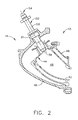
- FIG. 2 is a cross-sectional illustration of a portion of an exemplary combustor 16 that may be used with gas turbine engine 10.
- Combustor 16 includes an annular outer liner 40; an annular inner liner 42, and a domed end 44 that extends between outer and inner liners 40 and 42, respectively.
- Outer liner 40 and inner liner 42 are spaced radially inward from a combustor casing 46 and define a combustion chamber 48 therebetween.
- Combustor casing 46 is generally annular and extends around combustor 16.
- Combustion chamber 48 is generally annular in shape and is defined between from liners 40 and 42.
- a fuel nozzle 50 extends through domed end 44 for discharging fuel into combustion chamber 48, as described in more detail below.
- fuel nozzle 50 is aligned substantially concentrically with respect to combustor 16.
- fuel nozzle 50 includes an inlet 54, an injection or discharge tip 56, and a body 58 extending therebetween.
- Fuel nozzle 50 is a quad-annular fuel nozzle that includes a plurality of injection circuits 80 and a center axis of symmetry 81 extending therethrough. Specifically, injection circuits 80 are each routed independently through fuel nozzle 50 such that none of the injection circuits 80 are in flow communication with each other within nozzle 50.
- Fuel nozzle 50 includes a liquid fuel injection circuit 82, a gaseous fuel injection circuit 84, and a water injection circuit 86.
- Liquid fuel injection circuit 82 includes a primary fuel injection circuit 88 and a secondary fuel injection circuit 90 that are each coupled in flow communication to a liquid fuel source for injecting only liquid fuel downstream therefrom into combustion chamber 48.
- Primary fuel injection circuit 88 includes an annular fuel passageway 92 that extends substantially concentrically through nozzle 50 to an annular discharge opening 94.
- fuel passageway 92 and discharge opening 94 are each toroidal.
- fuel passageway 92 extends substantially coaxially through nozzle 50 with respect to axis of symmetry 81 such that passageway 92 is a radial distance D pf from axis of symmetry 81 such that fuel flowing therein flows substantially parallel to axis of symmetry 81 until flowing through an elbow 100.
- Elbow 100 is positioned upstream from, and in close proximity to, discharge opening 94 and directs liquid fuel into a convergent portion 102 of passageway 92 such that liquid fuel is discharged inwardly from passageway 92 towards axis of symmetry 81.
- Secondary fuel injection circuit 90 includes an annular fuel passageway 110 that extends substantially concentrically through nozzle 50 to annular discharge opening 94.
- fuel passageway 110 is toroidal and is radially outward from fuel passageway 92. More specifically, in the exemplary embodiment, fuel passageway 110 is substantially concentrically aligned with respect to fuel passageway 92, and with respect to axis of symmetry 81. Accordingly, liquid fuel flowing within passageway 110 flows substantially parallel to axis of symmetry 81 until flowing through an elbow 114.
- Elbow 114 is positioned upstream from, and in close proximity to, discharge opening 94 and directs liquid fuel into a convergent portion 116 of passageway 110 such that liquid fuel is discharged inwardly from passageway 110 towards axis of symmetry 81.
- Nozzle discharge tip 56 includes a nozzle portion 120 that extends divergently downstream from, and in flow communication with, opening 94. Accordingly, the combination of passageway convergent portions 102 and 116, opening 94, and divergent nozzle portion 120 creates a venturi that facilitates enhancing control of flow discharged from nozzle discharge tip 56. More specifically, the relative location of opening 94 within discharge tip 56 and with respect to nozzle portion 120 facilitates reducing dwell time for fuel within nozzle discharge tip 56, such that coking potential within nozzle discharge tip 56 is also facilitated to be reduced.
- Water injection circuit 86 is used to supply only water to combustion chamber 48 and includes an annular water injection passageway 130 that extends substantially concentrically through nozzle 50 to an annular discharge opening 132.
- fuel passageway 130 is toroidal and is positioned radially outward from fuel passageway 110. More specifically, in the exemplary embodiment, water injection passageway 130 is coupled to a water source and is substantially concentrically aligned with respect to fuel passageways 92 and 110, and with respect to axis of symmetry 81. Accordingly, water flowing within passageway 130 flows substantially parallel to axis of symmetry 81 until being discharged through annular discharge opening 132.
- opening 132 is a distance downstream from opening 94. Accordingly, the orientation of discharge opening 132 with respect to opening 94, ensures that water is discharged from opening 132 at a wider spray angle than that of the liquid fuel discharged from opening 94, thus facilitating nitrous oxide abatement.
- the narrower spray angle of the liquid fuel facilitates positioning the liquid fuel towards an aft end of the venturi, thus reducing dwell time and coking potential.
- Gaseous fuel injection circuit 84 is coupled to a gaseous fuel circuit such that only gaseous fuel is supplied to combustion chamber 48 during predetermined engine operating conditions by circuit 84.
- Gaseous fuel injection circuit 84 includes an annular fuel passageway 140 that extends substantially concentrically through nozzle 50 to a plurality of circumferentially-spaced discharge openings 142.
- fuel passageway 140 is toroidal and is positioned radially outward from water injection passageway 130.
- water injection passageway 130 is positioned radially between primary fuel injection circuit fuel passageway 92 and gaseous fuel injection fuel passageway 140.
- secondary fuel injection circuit fuel passageway 110 is positioned radially outward from gaseous fuel injection passageway 140.
- gaseous fuel injection passageway 140 is substantially concentrically aligned with respect to fuel passageways 92 and 110, and with respect to axis of symmetry 81. Accordingly, gaseous fuel flowing within passageway 140 flows substantially parallel to axis of symmetry 81 until being discharged through discharge openings 142.
- gaseous fuel injection openings 142 are oriented obliquely with respect to axis of symmetry 81. Accordingly, gaseous fuel discharged from openings 142 is expelled outwardly away from axis of symmetry 81.
- primary fuel injection circuit 88 During initial engine operation, and through engine idle operation, only primary fuel injection circuit 88 is used to supply fuel to combustion chamber 48. More specifically, primary fuel injection circuit 88 provides atomization of low fuel flows required for engine starting and transition to engine idle operation.
- secondary fuel injection circuit 90 provides up to approximately 95% of total liquid fuel flow required for high power engine operations.
- water is introduced to combustion chamber 48 through water injection circuit 86.
- Water injection facilitates abating nitrous oxide generation within combustion chamber 48.
- atomization is facilitated through a liquid water sheet formation induced by swirling the water flow within water injection circuit 86.
- bleed air from a compressor discharge is used to facilitate atomization of the water flow.
- natural gas flow is used to facilitate atomization of the water flow.
- the plurality of independent injection circuits 80 facilitates the independent optimization of each circuit for each mode of operation, including a liquid fuel dry mode, in which no water is injected into chamber 48, a liquid fuel + NO x water abatement mode of operation, and a gaseous fuel + NO x water abatement mode of operation. Accordingly, optimization of the circuits 80 is facilitated at all engine operational power settings.
- the above-described fuel nozzle provides a cost-effective and reliable means for reducing nitrous oxide emissions generated within a combustor.
- the fuel nozzle includes a plurality of independent injection circuits that facilitate enhanced optimization of fluids to be injected into the combustion chamber. More specifically, because water and fuel are not mixed within, or upstream from the fuel nozzle, the flows of each may be independently optimized. As a result, injection schemes are provided which facilitate reducing nitrous oxide emissions at substantially all engine operating conditions.
- a fuel nozzle An exemplary embodiment of a fuel nozzle is described above in detail.
- the fuel nozzle components illustrated are not limited to the specific embodiments described herein, but rather, components of each fuel nozzle may be utilized independently and separately from other components described herein.
- the plurality of injection circuits may be used with other fuel nozzles or in combination with other engine combustion systems.
Landscapes
- Engineering & Computer Science (AREA)
- Chemical & Material Sciences (AREA)
- Combustion & Propulsion (AREA)
- Mechanical Engineering (AREA)
- General Engineering & Computer Science (AREA)
- Fuel-Injection Apparatus (AREA)
- Nozzles (AREA)
Abstract
Description
- This invention relates generally to gas turbine engines, more particularly to combustors used with gas turbine engines.
- Known turbine engines include a compressor for compressing air which is suitably mixed with a fuel and channeled to a combustor wherein the mixture is ignited within a combustion chamber for generating hot combustion gases. More specifically, at least some known combustors include a dome assembly, a cowling, and liners to channel the combustion gases to a turbine, which extracts energy from the combustion gases for powering the compressor, as well as producing useful work to propel an aircraft in flight or to power a load, such as an electrical generator. Moreover, at least some known combustors include ignition devices, such as ignitors, primer nozzles, and/or pilot fuel nozzles, which are used during pre-selected engine operations to facilitate igniting the mixture within the combustion gases.
- At least some known fuel injectors are dual fuel injectors capable of supplying a liquid fuel, a gaseous fuel, or a mixture of liquid and gaseous fuels to the combustor. To facilitate reducing emissions within such combustors, at least some known combustors include water injection systems to facilitate nitrous oxide emission abatement. Within such systems, the water is premixed with the fuel during liquid fuel operation and is injected into the combustor through the fuel injector. Combining the water with liquid fuel in a single fuel circuit provides a design compromise, as the fuel/water mixture is optimized for flow and atomization, rather than requiring the liquid fuel and water to be individually optimized. However, within known fuel injectors, the water injection may provide only limited benefits, as the combined fuel/water mixture may become unmanageable at higher fuel flows.
- In one aspect of the present invention, a method for assembling a gas turbine engine is provided. The method comprises coupling a fuel nozzle within the engine to inject fuel into the engine, wherein the fuel nozzle includes three independent injection circuits arranged such that the second injection circuit is between the first and third injection circuits, coupling a liquid fuel source to a first injection circuit defined within the nozzle and including an annular discharge opening, and coupling a water source to one of the second injection circuit and the third injection circuits such that the water is coupled in flow communication to an annular discharge opening.
- In another aspect of the invention, a fuel nozzle for a gas turbine engine is provided. The fuel nozzle includes three injection circuits. A first injection circuit includes an annular discharge opening and is for injecting liquid fuel downstream from the nozzle into the gas turbine engine. The second injection circuit is aligned substantially concentrically with respect to the first injection circuit. The third injection circuit is aligned substantially concentrically with respect to the first injection circuit, such that the second injection circuit is between the second and third injection circuits. One of the second and third injection circuits is for injecting water downstream from the nozzle into the gas turbine engine. One of the second injection circuit and the third injection circuit includes an annular discharge opening.
- In a further aspect a gas turbine engine includes a combustor including a combustion chamber and at least one fuel nozzle. At least one fuel nozzle includes three injection circuits. The first injection circuit includes an annular discharge opening and is for injecting only liquid fuel into the combustion chamber. The second injection circuit is aligned substantially concentrically with respect to the first and third injection circuits, such that the second injection circuit extends between the first and third injection circuits. One of the second and third injection circuits includes an annular discharge. One of the second and third injection circuits is for only injecting water into the combustion chamber.
- Embodiments of the invention will now be described, by way of example, with reference to the accompanying drawings, in which:
- Figure 1 is a schematic of an exemplary gas turbine engine.
- Figure 2 is a cross-sectional illustration of an exemplary combustor that may be used with the gas turbine engine shown in Figure 1
- Figure 3 is an enlarged cross-sectional view of a portion of the fuel nozzle shown in Figure 2; and
- Figure 4 is an end view of the fuel nozzle shown in Figure 3.
- Figure 1 is a schematic illustration of a
gas turbine engine 10 including alow pressure compressor 12, ahigh pressure compressor 14, and acombustor 16.Engine 10 also includes ahigh pressure turbine 18 and alow pressure turbine 20.Compressor 12 andturbine 20 are coupled by afirst shaft 22, andcompressor 14 andturbine 18 are coupled by asecond shaft 21. - In operation, air flows through
low pressure compressor 12 and compressed air is supplied fromlow pressure compressor 12 tohigh pressure compressor 14. The highly compressed air is delivered tocombustor 16. Airflow from combustor 16exits combustor 16 and drivesturbines gas turbine engine 10. - Figure 2 is a cross-sectional illustration of a portion of an
exemplary combustor 16 that may be used withgas turbine engine 10.Combustor 16 includes an annularouter liner 40; an annularinner liner 42, and adomed end 44 that extends between outer andinner liners Outer liner 40 andinner liner 42 are spaced radially inward from acombustor casing 46 and define acombustion chamber 48 therebetween.Combustor casing 46 is generally annular and extends aroundcombustor 16.Combustion chamber 48 is generally annular in shape and is defined between fromliners - A
fuel nozzle 50 extends throughdomed end 44 for discharging fuel intocombustion chamber 48, as described in more detail below. In one embodiment,fuel nozzle 50 is aligned substantially concentrically with respect tocombustor 16. In the exemplary embodiment,fuel nozzle 50 includes aninlet 54, an injection ordischarge tip 56, and abody 58 extending therebetween. - Figure 3 is an enlarged side view of a portion of
fuel nozzle 50, and Figure 4 is an end view offuel nozzle 50.Fuel nozzle 50 is a quad-annular fuel nozzle that includes a plurality ofinjection circuits 80 and a center axis ofsymmetry 81 extending therethrough. Specifically,injection circuits 80 are each routed independently throughfuel nozzle 50 such that none of theinjection circuits 80 are in flow communication with each other withinnozzle 50. -
Fuel nozzle 50 includes a liquidfuel injection circuit 82, a gaseousfuel injection circuit 84, and awater injection circuit 86. Liquidfuel injection circuit 82 includes a primaryfuel injection circuit 88 and a secondaryfuel injection circuit 90 that are each coupled in flow communication to a liquid fuel source for injecting only liquid fuel downstream therefrom intocombustion chamber 48. Primaryfuel injection circuit 88 includes anannular fuel passageway 92 that extends substantially concentrically throughnozzle 50 to anannular discharge opening 94. In the exemplary embodiment,fuel passageway 92 anddischarge opening 94 are each toroidal. - In the exemplary embodiment,
fuel passageway 92 extends substantially coaxially throughnozzle 50 with respect to axis ofsymmetry 81 such thatpassageway 92 is a radial distance Dpf from axis ofsymmetry 81 such that fuel flowing therein flows substantially parallel to axis ofsymmetry 81 until flowing through anelbow 100. Elbow 100 is positioned upstream from, and in close proximity to, discharge opening 94 and directs liquid fuel into aconvergent portion 102 ofpassageway 92 such that liquid fuel is discharged inwardly frompassageway 92 towards axis ofsymmetry 81. - Secondary
fuel injection circuit 90 includes anannular fuel passageway 110 that extends substantially concentrically throughnozzle 50 toannular discharge opening 94. In the exemplary embodiment,fuel passageway 110 is toroidal and is radially outward fromfuel passageway 92. More specifically, in the exemplary embodiment,fuel passageway 110 is substantially concentrically aligned with respect tofuel passageway 92, and with respect to axis ofsymmetry 81. Accordingly, liquid fuel flowing withinpassageway 110 flows substantially parallel to axis ofsymmetry 81 until flowing through anelbow 114. Elbow 114 is positioned upstream from, and in close proximity to, discharge opening 94 and directs liquid fuel into aconvergent portion 116 ofpassageway 110 such that liquid fuel is discharged inwardly frompassageway 110 towards axis ofsymmetry 81. -
Nozzle discharge tip 56 includes anozzle portion 120 that extends divergently downstream from, and in flow communication with, opening 94. Accordingly, the combination of passagewayconvergent portions divergent nozzle portion 120 creates a venturi that facilitates enhancing control of flow discharged fromnozzle discharge tip 56. More specifically, the relative location of opening 94 withindischarge tip 56 and with respect tonozzle portion 120 facilitates reducing dwell time for fuel withinnozzle discharge tip 56, such that coking potential withinnozzle discharge tip 56 is also facilitated to be reduced. -
Water injection circuit 86 is used to supply only water tocombustion chamber 48 and includes an annularwater injection passageway 130 that extends substantially concentrically throughnozzle 50 to anannular discharge opening 132. In the exemplary embodiment,fuel passageway 130 is toroidal and is positioned radially outward fromfuel passageway 110. More specifically, in the exemplary embodiment,water injection passageway 130 is coupled to a water source and is substantially concentrically aligned with respect tofuel passageways symmetry 81. Accordingly, water flowing withinpassageway 130 flows substantially parallel to axis ofsymmetry 81 until being discharged throughannular discharge opening 132. In the exemplary embodiment, opening 132 is a distance downstream from opening 94. Accordingly, the orientation of discharge opening 132 with respect to opening 94, ensures that water is discharged from opening 132 at a wider spray angle than that of the liquid fuel discharged from opening 94, thus facilitating nitrous oxide abatement. - Moreover, the narrower spray angle of the liquid fuel facilitates positioning the liquid fuel towards an aft end of the venturi, thus reducing dwell time and coking potential.
- Gaseous
fuel injection circuit 84 is coupled to a gaseous fuel circuit such that only gaseous fuel is supplied tocombustion chamber 48 during predetermined engine operating conditions bycircuit 84. Gaseousfuel injection circuit 84 includes anannular fuel passageway 140 that extends substantially concentrically throughnozzle 50 to a plurality of circumferentially-spaceddischarge openings 142. In the exemplary embodiment,fuel passageway 140 is toroidal and is positioned radially outward fromwater injection passageway 130. In an alternative embodiment,water injection passageway 130 is positioned radially between primary fuel injectioncircuit fuel passageway 92 and gaseous fuelinjection fuel passageway 140. Within such an embodiment, secondary fuel injectioncircuit fuel passageway 110 is positioned radially outward from gaseousfuel injection passageway 140. More specifically, in the exemplary embodiment, gaseousfuel injection passageway 140 is substantially concentrically aligned with respect tofuel passageways symmetry 81. Accordingly, gaseous fuel flowing withinpassageway 140 flows substantially parallel to axis ofsymmetry 81 until being discharged throughdischarge openings 142. - In the exemplary embodiment, gaseous
fuel injection openings 142 are oriented obliquely with respect to axis ofsymmetry 81. Accordingly, gaseous fuel discharged fromopenings 142 is expelled outwardly away from axis ofsymmetry 81. - During initial engine operation, and through engine idle operation, only primary
fuel injection circuit 88 is used to supply fuel tocombustion chamber 48. More specifically, primaryfuel injection circuit 88 provides atomization of low fuel flows required for engine starting and transition to engine idle operation. - During higher power operations, the remaining liquid fuel required for operation is injected through secondary
fuel injection circuit 90, and gaseous fuel may be injected through gaseousfuel injection circuit 84. In one embodiment, secondaryfuel injection circuit 90 provides up to approximately 95% of total liquid fuel flow required for high power engine operations. During such operations, water is introduced tocombustion chamber 48 throughwater injection circuit 86. Water injection facilitates abating nitrous oxide generation withincombustion chamber 48. Moreover, in the exemplary embodiment, atomization is facilitated through a liquid water sheet formation induced by swirling the water flow withinwater injection circuit 86. In an alternative embodiment, bleed air from a compressor discharge is used to facilitate atomization of the water flow. In a further alternative embodiment, natural gas flow is used to facilitate atomization of the water flow. - Because fuel is injected through independent injection circuits, the plurality of
independent injection circuits 80 facilitates the independent optimization of each circuit for each mode of operation, including a liquid fuel dry mode, in which no water is injected intochamber 48, a liquid fuel + NOx water abatement mode of operation, and a gaseous fuel + NOx water abatement mode of operation. Accordingly, optimization of thecircuits 80 is facilitated at all engine operational power settings. - The above-described fuel nozzle provides a cost-effective and reliable means for reducing nitrous oxide emissions generated within a combustor. The fuel nozzle includes a plurality of independent injection circuits that facilitate enhanced optimization of fluids to be injected into the combustion chamber. More specifically, because water and fuel are not mixed within, or upstream from the fuel nozzle, the flows of each may be independently optimized. As a result, injection schemes are provided which facilitate reducing nitrous oxide emissions at substantially all engine operating conditions.
- An exemplary embodiment of a fuel nozzle is described above in detail. The fuel nozzle components illustrated are not limited to the specific embodiments described herein, but rather, components of each fuel nozzle may be utilized independently and separately from other components described herein. For example, the plurality of injection circuits may be used with other fuel nozzles or in combination with other engine combustion systems.
Claims (10)
- A fuel nozzle (50) for a gas turbine engine (10), said fuel nozzle comprising:a first injection circuit (82) comprising an annular discharge opening (94), said first injection circuit for injecting liquid fuel downstream from said nozzle into the gas turbine engine;a second injection circuit (84) aligned substantially concentrically with respect to said first injection circuit; anda third injection circuit (86) aligned substantially concentrically with respect to said first injection circuit, said second injection circuit is between said second and third injection circuits, one of said second and third injection circuits for injecting water downstream from said nozzle into the gas turbine engine, one of said second injection circuit and said third injection circuit comprising an annular discharge opening (132).
- A fuel nozzle (50) in accordance with Claim 1 wherein said first injection circuit (82) comprises a primary fuel circuit (88) and a secondary fuel circuit (90), said primary fuel circuit radially inward from said secondary fuel circuit.
- A fuel nozzle (50) in accordance with Claim 1 wherein only said primary fuel circuit (88) is configured to inject fuel into the gas turbine engine (10) during engine start-up and idle operating conditions.
- A fuel nozzle (50) in accordance with Claim 1 further comprising a centerline axis of symmetry (81), said first injection circuit (82) is a radial distance from said centerline axis of symmetry.
- A fuel nozzle (50) in accordance with Claim 1 wherein one of said second injection circuit (84) and said third injection circuit (86) comprises a plurality of circumferentially-spaced discharge openings (142).
- A fuel nozzle (50) in accordance with Claim 1 further comprising a centerline axis of symmetry (81), said third injection circuit (86) comprises a plurality of circumferentially-spaced discharge openings (142) configured to discharge fluids obliquely outward from said nozzle with respect to said centerline axis of symmetry.
- A fuel nozzle (50) in accordance with Claim 1 wherein one of said second injection circuit (84) and said third injection circuit (86) is configured to only inject gaseous fuel downstream from said nozzle into the gas turbine engine (10).
- A gas turbine engine (10) comprising a combustor (16) comprising a combustion chamber (48) and at least one fuel nozzle (50), said at least one fuel nozzle comprising a first injection circuit (82), a second injection circuit (84), and a third injection circuit (86), said first injection circuit comprising an annular discharge opening (94), said first injection circuit for injecting only liquid fuel into said combustion chamber, said second injection circuit is aligned substantially concentrically with respect to said first and third injection circuits, such that said second injection circuit extends between said first and third injection circuits, one of said second and third injection circuits comprises an annular discharge (132), one of said second and third injection circuits is for only injecting water into said combustion chamber.
- A gas turbine engine in accordance with Claim 8 wherein said first injection circuit (82) comprises a primary fuel circuit (88) and a secondary fuel circuit (90), said primary fuel circuit radially inward from said secondary fuel circuit, said primary fuel circuit is configured to inject liquid fuel into said combustion chamber (48) only during engine-start up and idle operating conditions.
- A gas turbine engine (10) in accordance with Claim 9 wherein one of said second injection circuit (84) and said third injection circuit (86) is configured to only inject gaseous fuel into said combustion chamber (48), said nozzle (50) comprises an axis of symmetry (81) extending therethrough, said first injection circuit (82) is oriented to discharge liquid fuel from said nozzle in a direction that is substantially parallel to said axis of symmetry, said second injection circuit is oriented to discharge water from said nozzle in a direction that is substantially parallel to said axis of symmetry, said third injection circuit is oriented to discharge gaseous fuel from said nozzle in an oblique direction with respect to said axis of symmetry.
Applications Claiming Priority (1)
| Application Number | Priority Date | Filing Date | Title |
|---|---|---|---|
| US10/931,550 US7082765B2 (en) | 2004-09-01 | 2004-09-01 | Methods and apparatus for reducing gas turbine engine emissions |
Publications (1)
| Publication Number | Publication Date |
|---|---|
| EP1632716A1 true EP1632716A1 (en) | 2006-03-08 |
Family
ID=35406210
Family Applications (1)
| Application Number | Title | Priority Date | Filing Date |
|---|---|---|---|
| EP05255347A Withdrawn EP1632716A1 (en) | 2004-09-01 | 2005-09-01 | Methods and apparatus for reducing gas turbine engine emissions |
Country Status (4)
| Country | Link |
|---|---|
| US (1) | US7082765B2 (en) |
| EP (1) | EP1632716A1 (en) |
| JP (1) | JP5393938B2 (en) |
| CA (1) | CA2516753C (en) |
Cited By (2)
| Publication number | Priority date | Publication date | Assignee | Title |
|---|---|---|---|---|
| CN102374027A (en) * | 2010-08-11 | 2012-03-14 | 通用电气公司 | Modular tip injection devices and method of assembling same |
| EP4722594A1 (en) * | 2024-10-01 | 2026-04-08 | General Electric Company | Gas turbine engine including fuel nozzle assembly |
Families Citing this family (15)
| Publication number | Priority date | Publication date | Assignee | Title |
|---|---|---|---|---|
| US7249460B2 (en) * | 2002-01-29 | 2007-07-31 | Nearhoof Jr Charles F | Fuel injection system for a turbine engine |
| US7152411B2 (en) * | 2003-06-27 | 2006-12-26 | General Electric Company | Rabbet mounted combuster |
| US7520134B2 (en) * | 2006-09-29 | 2009-04-21 | General Electric Company | Methods and apparatus for injecting fluids into a turbine engine |
| EP2014978A1 (en) * | 2007-07-10 | 2009-01-14 | Siemens Aktiengesellschaft | Use of insert gases for shielding oxidiser from fuel |
| US20100242490A1 (en) * | 2009-03-31 | 2010-09-30 | General Electric Company | Additive delivery systems and methods |
| US20100263382A1 (en) * | 2009-04-16 | 2010-10-21 | Alfred Albert Mancini | Dual orifice pilot fuel injector |
| US20120216773A1 (en) * | 2009-06-30 | 2012-08-30 | Orbital Australia Pty Ltd | Injection of gaseous fuels |
| US8899051B2 (en) | 2010-12-30 | 2014-12-02 | Rolls-Royce Corporation | Gas turbine engine flange assembly including flow circuit |
| US20120255472A1 (en) * | 2011-04-06 | 2012-10-11 | Gordon Norman R | Burner assembly and method for reducing nox emissions |
| US9321642B2 (en) * | 2013-12-04 | 2016-04-26 | L'Air Liquide Société´Anonyme Pour L'Étude Et L'Exploitation Des Procedes Georges Claude | Method for decreasing SMR tube temperature |
| CN105940265A (en) | 2013-12-04 | 2016-09-14 | 阿卜杜拉国王科技大学 | Apparatuses and methods for combustion and material synthesis |
| EP3077722B1 (en) | 2013-12-04 | 2020-02-05 | King Abdullah University Of Science And Technology | Apparatuses and methods for combustion |
| CN106574774A (en) * | 2014-08-14 | 2017-04-19 | 西门子公司 | Multi-functional fuel nozzle with an atomizer array |
| US10443855B2 (en) | 2014-10-23 | 2019-10-15 | Siemens Aktiengesellschaft | Flexible fuel combustion system for turbine engines |
| US20240418127A1 (en) * | 2023-06-16 | 2024-12-19 | Raytheon Technologies Corporation | Gaseous fuel and liquid water injection for turbine engine |
Citations (7)
| Publication number | Priority date | Publication date | Assignee | Title |
|---|---|---|---|---|
| US2810433A (en) * | 1952-01-17 | 1957-10-22 | Texas Co | Burner for oil-fired gas generator |
| US3498059A (en) * | 1967-03-20 | 1970-03-03 | Rolls Royce | Burner,e.g.,for a gas turbine engine combustion chamber |
| US3826080A (en) * | 1973-03-15 | 1974-07-30 | Westinghouse Electric Corp | System for reducing nitrogen-oxygen compound in the exhaust of a gas turbine |
| US4327547A (en) * | 1978-11-23 | 1982-05-04 | Rolls-Royce Limited | Fuel injectors |
| GB2088037A (en) * | 1980-11-25 | 1982-06-03 | Gen Electric | Fuel Nozzle for a Gas Turbine Engine |
| US5729968A (en) * | 1995-08-08 | 1998-03-24 | General Electric Co. | Center burner in a multi-burner combustor |
| EP0905443A2 (en) * | 1997-09-30 | 1999-03-31 | General Electric Company | Dual-fuel nozzle for inhibiting carbon deposition onto combustor surfaces in a gas turbine |
Family Cites Families (21)
| Publication number | Priority date | Publication date | Assignee | Title |
|---|---|---|---|---|
| US4600151A (en) * | 1982-11-23 | 1986-07-15 | Ex-Cell-O Corporation | Fuel injector assembly with water or auxiliary fuel capability |
| JPH05215338A (en) * | 1992-01-31 | 1993-08-24 | Mitsubishi Heavy Ind Ltd | Gas turbine combustion device and its combustion method |
| US5259184A (en) * | 1992-03-30 | 1993-11-09 | General Electric Company | Dry low NOx single stage dual mode combustor construction for a gas turbine |
| JP3174634B2 (en) * | 1992-08-11 | 2001-06-11 | 三菱重工業株式会社 | Gas turbine fuel injection system |
| IT1263683B (en) * | 1992-08-21 | 1996-08-27 | Westinghouse Electric Corp | NOZZLE COMPLEX FOR FUEL FOR A GAS TURBINE |
| US5408830A (en) * | 1994-02-10 | 1995-04-25 | General Electric Company | Multi-stage fuel nozzle for reducing combustion instabilities in low NOX gas turbines |
| US5435126A (en) * | 1994-03-14 | 1995-07-25 | General Electric Company | Fuel nozzle for a turbine having dual capability for diffusion and premix combustion and methods of operation |
| US5713205A (en) * | 1996-08-06 | 1998-02-03 | General Electric Co. | Air atomized discrete jet liquid fuel injector and method |
| US5836163A (en) * | 1996-11-13 | 1998-11-17 | Solar Turbines Incorporated | Liquid pilot fuel injection method and apparatus for a gas turbine engine dual fuel injector |
| US5826423A (en) * | 1996-11-13 | 1998-10-27 | Solar Turbines Incorporated | Dual fuel injection method and apparatus with multiple air blast liquid fuel atomizers |
| US5833141A (en) * | 1997-05-30 | 1998-11-10 | General Electric Company | Anti-coking dual-fuel nozzle for a gas turbine combustor |
| JP2000039148A (en) * | 1998-07-21 | 2000-02-08 | Mitsubishi Heavy Ind Ltd | Gas turbine combustor nozzle |
| JP3457907B2 (en) * | 1998-12-24 | 2003-10-20 | 三菱重工業株式会社 | Dual fuel nozzle |
| US6598383B1 (en) * | 1999-12-08 | 2003-07-29 | General Electric Co. | Fuel system configuration and method for staging fuel for gas turbines utilizing both gaseous and liquid fuels |
| JP4246874B2 (en) * | 2000-03-10 | 2009-04-02 | 三菱重工業株式会社 | Multifunctional water injection manifold and operation method thereof |
| US6415594B1 (en) * | 2000-05-31 | 2002-07-09 | General Electric Company | Methods and apparatus for reducing gas turbine engine emissions |
| US6609380B2 (en) * | 2001-12-28 | 2003-08-26 | General Electric Company | Liquid fuel nozzle apparatus with passive protective purge |
| US7165405B2 (en) * | 2002-07-15 | 2007-01-23 | Power Systems Mfg. Llc | Fully premixed secondary fuel nozzle with dual fuel capability |
| US6722132B2 (en) * | 2002-07-15 | 2004-04-20 | Power Systems Mfg, Llc | Fully premixed secondary fuel nozzle with improved stability and dual fuel capability |
| US6915636B2 (en) * | 2002-07-15 | 2005-07-12 | Power Systems Mfg., Llc | Dual fuel fin mixer secondary fuel nozzle |
| US7143583B2 (en) * | 2002-08-22 | 2006-12-05 | Hitachi, Ltd. | Gas turbine combustor, combustion method of the gas turbine combustor, and method of remodeling a gas turbine combustor |
-
2004
- 2004-09-01 US US10/931,550 patent/US7082765B2/en not_active Expired - Lifetime
-
2005
- 2005-08-18 CA CA2516753A patent/CA2516753C/en not_active Expired - Fee Related
- 2005-09-01 EP EP05255347A patent/EP1632716A1/en not_active Withdrawn
- 2005-09-01 JP JP2005253097A patent/JP5393938B2/en not_active Expired - Fee Related
Patent Citations (7)
| Publication number | Priority date | Publication date | Assignee | Title |
|---|---|---|---|---|
| US2810433A (en) * | 1952-01-17 | 1957-10-22 | Texas Co | Burner for oil-fired gas generator |
| US3498059A (en) * | 1967-03-20 | 1970-03-03 | Rolls Royce | Burner,e.g.,for a gas turbine engine combustion chamber |
| US3826080A (en) * | 1973-03-15 | 1974-07-30 | Westinghouse Electric Corp | System for reducing nitrogen-oxygen compound in the exhaust of a gas turbine |
| US4327547A (en) * | 1978-11-23 | 1982-05-04 | Rolls-Royce Limited | Fuel injectors |
| GB2088037A (en) * | 1980-11-25 | 1982-06-03 | Gen Electric | Fuel Nozzle for a Gas Turbine Engine |
| US5729968A (en) * | 1995-08-08 | 1998-03-24 | General Electric Co. | Center burner in a multi-burner combustor |
| EP0905443A2 (en) * | 1997-09-30 | 1999-03-31 | General Electric Company | Dual-fuel nozzle for inhibiting carbon deposition onto combustor surfaces in a gas turbine |
Cited By (3)
| Publication number | Priority date | Publication date | Assignee | Title |
|---|---|---|---|---|
| CN102374027A (en) * | 2010-08-11 | 2012-03-14 | 通用电气公司 | Modular tip injection devices and method of assembling same |
| CN102374027B (en) * | 2010-08-11 | 2016-06-15 | 通用电气公司 | Modular tip injection devices |
| EP4722594A1 (en) * | 2024-10-01 | 2026-04-08 | General Electric Company | Gas turbine engine including fuel nozzle assembly |
Also Published As
| Publication number | Publication date |
|---|---|
| JP5393938B2 (en) | 2014-01-22 |
| CA2516753A1 (en) | 2006-03-01 |
| CA2516753C (en) | 2014-01-07 |
| JP2006071275A (en) | 2006-03-16 |
| US20060042253A1 (en) | 2006-03-02 |
| US7082765B2 (en) | 2006-08-01 |
Similar Documents
| Publication | Publication Date | Title |
|---|---|---|
| CN105698175B (en) | Premix nozzle with integrated liquid evaporator | |
| US7716931B2 (en) | Method and apparatus for assembling gas turbine engine | |
| EP2481982B2 (en) | Mixer assembly for a gas turbine engine | |
| EP0769657B1 (en) | Low emissions combustor premixer | |
| CA2516753C (en) | Methods and apparatus for reducing gas turbine engine emissions | |
| US6474070B1 (en) | Rich double dome combustor | |
| EP2241816A2 (en) | Dual orifice pilot fuel injector | |
| US8099940B2 (en) | Low cross-talk gas turbine fuel injector | |
| CN114008387A (en) | Second stage combustion for igniters | |
| CN107923620B (en) | System and method for multi-fuel premixing nozzle with integral liquid injector/evaporator | |
| US12152780B2 (en) | Method of supplying fuel and air to a combustor with an ignition tube | |
| EP3376109B1 (en) | Dual-fuel fuel nozzle with liquid fuel tip | |
| US11859821B2 (en) | Passive secondary air assist nozzles | |
| US20240263786A1 (en) | Central air passage with radial fuel distributor | |
| EP4411240A1 (en) | Combined air swirler and fuel distributor | |
| JP2026047200A (en) | Simultaneous firing of a combustor using gaseous fuel and liquid ammonia. |
Legal Events
| Date | Code | Title | Description |
|---|---|---|---|
| PUAI | Public reference made under article 153(3) epc to a published international application that has entered the european phase |
Free format text: ORIGINAL CODE: 0009012 |
|
| AK | Designated contracting states |
Kind code of ref document: A1 Designated state(s): AT BE BG CH CY CZ DE DK EE ES FI FR GB GR HU IE IS IT LI LT LU LV MC NL PL PT RO SE SI SK TR |
|
| AX | Request for extension of the european patent |
Extension state: AL BA HR MK YU |
|
| 17P | Request for examination filed |
Effective date: 20060908 |
|
| 17Q | First examination report despatched |
Effective date: 20061012 |
|
| AKX | Designation fees paid |
Designated state(s): DE FR GB |
|
| GRAP | Despatch of communication of intention to grant a patent |
Free format text: ORIGINAL CODE: EPIDOSNIGR1 |
|
| INTG | Intention to grant announced |
Effective date: 20171004 |
|
| STAA | Information on the status of an ep patent application or granted ep patent |
Free format text: STATUS: THE APPLICATION IS DEEMED TO BE WITHDRAWN |
|
| 18D | Application deemed to be withdrawn |
Effective date: 20180215 |