EP1632686A2 - A pressure compensating device for a bearing housing - Google Patents
A pressure compensating device for a bearing housing Download PDFInfo
- Publication number
- EP1632686A2 EP1632686A2 EP05105938A EP05105938A EP1632686A2 EP 1632686 A2 EP1632686 A2 EP 1632686A2 EP 05105938 A EP05105938 A EP 05105938A EP 05105938 A EP05105938 A EP 05105938A EP 1632686 A2 EP1632686 A2 EP 1632686A2
- Authority
- EP
- European Patent Office
- Prior art keywords
- bellows
- pressure
- pressure compensating
- compensating device
- housing
- Prior art date
- Legal status (The legal status is an assumption and is not a legal conclusion. Google has not performed a legal analysis and makes no representation as to the accuracy of the status listed.)
- Granted
Links
Images


Classifications
-
- B—PERFORMING OPERATIONS; TRANSPORTING
- B22—CASTING; POWDER METALLURGY
- B22D—CASTING OF METALS; CASTING OF OTHER SUBSTANCES BY THE SAME PROCESSES OR DEVICES
- B22D11/00—Continuous casting of metals, i.e. casting in indefinite lengths
- B22D11/12—Accessories for subsequent treating or working cast stock in situ
- B22D11/128—Accessories for subsequent treating or working cast stock in situ for removing
- B22D11/1287—Rolls; Lubricating, cooling or heating rolls while in use
-
- F—MECHANICAL ENGINEERING; LIGHTING; HEATING; WEAPONS; BLASTING
- F16—ENGINEERING ELEMENTS AND UNITS; GENERAL MEASURES FOR PRODUCING AND MAINTAINING EFFECTIVE FUNCTIONING OF MACHINES OR INSTALLATIONS; THERMAL INSULATION IN GENERAL
- F16C—SHAFTS; FLEXIBLE SHAFTS; ELEMENTS OR CRANKSHAFT MECHANISMS; ROTARY BODIES OTHER THAN GEARING ELEMENTS; BEARINGS
- F16C41/00—Other accessories, e.g. devices integrated in the bearing not relating to the bearing function as such
-
- F—MECHANICAL ENGINEERING; LIGHTING; HEATING; WEAPONS; BLASTING
- F16—ENGINEERING ELEMENTS AND UNITS; GENERAL MEASURES FOR PRODUCING AND MAINTAINING EFFECTIVE FUNCTIONING OF MACHINES OR INSTALLATIONS; THERMAL INSULATION IN GENERAL
- F16C—SHAFTS; FLEXIBLE SHAFTS; ELEMENTS OR CRANKSHAFT MECHANISMS; ROTARY BODIES OTHER THAN GEARING ELEMENTS; BEARINGS
- F16C13/00—Rolls, drums, discs, or the like; Bearings or mountings therefor
- F16C13/02—Bearings
-
- F—MECHANICAL ENGINEERING; LIGHTING; HEATING; WEAPONS; BLASTING
- F16—ENGINEERING ELEMENTS AND UNITS; GENERAL MEASURES FOR PRODUCING AND MAINTAINING EFFECTIVE FUNCTIONING OF MACHINES OR INSTALLATIONS; THERMAL INSULATION IN GENERAL
- F16C—SHAFTS; FLEXIBLE SHAFTS; ELEMENTS OR CRANKSHAFT MECHANISMS; ROTARY BODIES OTHER THAN GEARING ELEMENTS; BEARINGS
- F16C33/00—Parts of bearings; Special methods for making bearings or parts thereof
- F16C33/72—Sealings
- F16C33/723—Shaft end sealing means, e.g. cup-shaped caps or covers
-
- F—MECHANICAL ENGINEERING; LIGHTING; HEATING; WEAPONS; BLASTING
- F16—ENGINEERING ELEMENTS AND UNITS; GENERAL MEASURES FOR PRODUCING AND MAINTAINING EFFECTIVE FUNCTIONING OF MACHINES OR INSTALLATIONS; THERMAL INSULATION IN GENERAL
- F16C—SHAFTS; FLEXIBLE SHAFTS; ELEMENTS OR CRANKSHAFT MECHANISMS; ROTARY BODIES OTHER THAN GEARING ELEMENTS; BEARINGS
- F16C33/00—Parts of bearings; Special methods for making bearings or parts thereof
- F16C33/72—Sealings
- F16C33/726—Sealings with means to vent the interior of the bearing
-
- F—MECHANICAL ENGINEERING; LIGHTING; HEATING; WEAPONS; BLASTING
- F16—ENGINEERING ELEMENTS AND UNITS; GENERAL MEASURES FOR PRODUCING AND MAINTAINING EFFECTIVE FUNCTIONING OF MACHINES OR INSTALLATIONS; THERMAL INSULATION IN GENERAL
- F16C—SHAFTS; FLEXIBLE SHAFTS; ELEMENTS OR CRANKSHAFT MECHANISMS; ROTARY BODIES OTHER THAN GEARING ELEMENTS; BEARINGS
- F16C33/00—Parts of bearings; Special methods for making bearings or parts thereof
- F16C33/72—Sealings
- F16C33/76—Sealings of ball or roller bearings
-
- F—MECHANICAL ENGINEERING; LIGHTING; HEATING; WEAPONS; BLASTING
- F16—ENGINEERING ELEMENTS AND UNITS; GENERAL MEASURES FOR PRODUCING AND MAINTAINING EFFECTIVE FUNCTIONING OF MACHINES OR INSTALLATIONS; THERMAL INSULATION IN GENERAL
- F16C—SHAFTS; FLEXIBLE SHAFTS; ELEMENTS OR CRANKSHAFT MECHANISMS; ROTARY BODIES OTHER THAN GEARING ELEMENTS; BEARINGS
- F16C35/00—Rigid support of bearing units; Housings, e.g. caps, covers
- F16C35/04—Rigid support of bearing units; Housings, e.g. caps, covers in the case of ball or roller bearings
-
- F—MECHANICAL ENGINEERING; LIGHTING; HEATING; WEAPONS; BLASTING
- F16—ENGINEERING ELEMENTS AND UNITS; GENERAL MEASURES FOR PRODUCING AND MAINTAINING EFFECTIVE FUNCTIONING OF MACHINES OR INSTALLATIONS; THERMAL INSULATION IN GENERAL
- F16C—SHAFTS; FLEXIBLE SHAFTS; ELEMENTS OR CRANKSHAFT MECHANISMS; ROTARY BODIES OTHER THAN GEARING ELEMENTS; BEARINGS
- F16C2322/00—Apparatus used in shaping articles
Definitions
- the present invention relates to pressure compensating device for a bearing housing, particularly for supporting rollers in continuous casting machines.
- Rollers of continuous casting machines are used for supporting, forming and cooling a solidifying slab of material, fed out from a water-cooled mould.
- the rollers are subjected to a particularly unfriendly environment, with the hot, water-cooled slab, scales and steam generated as the water is cooling off the slab.
- the rollers are provided with internal siphone pipes for cooling water.
- the rollers are subjected to varying temperatures and in order to reduce the effects of length changes caused by temperature variations, the rollers are axially subdivided in segments, which are supported in rolling bearings positioned in stands.
- a bearing which is positioned in a housing compartment, which is sealed off on both sides. Between the ends of two roller segments facing each other the same sealed off compartment can incorporate the adjacent bearings for the ends of the two adjacent roller segments.
- a problem is that the seals due to pressure differences building up during varied temperatures, can cause the seals to become displaced to such an extent that their sealing capacity is reduced or even lost.
- the purpose of the present invention is to propose a pressure compensating device arranged to prevent such build up of pressure differences and this has been achieved in that the pressure compensating device has been given the characteristics defined in the accompanying claim 1.
- Fig. 1 illustrates in a schematic cross sectional view a portion of an end roller segment of a continuous caster roller 1, which is rotationally supported in a bearing 2, which has its outer race ring resting on a roll stand 3.
- a pressure compensator 4 acting to equalize the pressure within the space between the seals 2a, as the pressure varies inside the roll segment following temperature variations caused by the solidifying hot steel slab both due to contact against the outer envelope surface of the roll segment and due to convection from the hot steel slab.
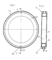
- the pressure compensating device 4 is shown separate and in perspective in Fig. 2, and Fig. 3 shows a cross section of a portion of the device.
- the compensating device 4 incorporates a wheel-formed body with an axially extending outer rim 5 and hub portion 6 interconnected with the rim 5 via a planar annular web 7 of smaller axial size than the rim 5.
- the annular web 7 is in plane with one side edge of the rim 5, whereas the hub portion has a first planar side surface, which is in plane with the opposite side edge of the rim 5, thereby creating an annular through-shaped channel 8 between the rim 5 and the hub member 6.
- this annular through-shaped channel 8 is arranged a flexible bellows 9 having one side edge 9a firmly and air-tightly bonded to the first planar side surface of the hub portion 6, whereas the opposite side edge 9b thereof is firmly and air-tightly bonded to the planar side of the rim 5, which is in plane with the first side of the hub portion 6.
- the part of the flexible bellows situated between the side edges 9a, 9b being loosely arranged along the bottom of the through-shaped channel 8, without being connected thereto.
- the connection between the side edges 9a and 9b and their contact surfaces can preferably be achieved by vulcanisation, but it is also possible to use glueing or another appropriate method giving durable, air-proof joints.
- a tube 10 is inserted through the wall of the bellows for extending between the outside of the bellows 9 and the space between the bellows 9 and the bottom of the through-shaped channel 8.
- the end of this tube 10 projecting outside the bellows 9 is intended to be positioned with its open end in the area around the bearing 2, where pressure variations can occur, such as illustrated in Fig. 1.
- the pressure compensating device thus is designed as a cassette with a rigid supporting disc having an annular recess in which is positioned a bellows of a resilient, air-tight material, which has been bonded to the edges surrounding the recess, whereas the bellows is freely movable between the bonded edges.
- the bellows is therefore well protected and the fact that it can be delivered as a separate cassette, makes it easily mounted in correct position and with the parts in exact mutual positions in the bearing housing.
- Fig. 4 shows in a very schematic sketch a portion of an area between two roll segments 11, each one being supported in roller bearings 12, and with a pressure compensating device 14 according to the invention, which is arranged to equalize pressure variations inside the space sealed off by seals 12a.
- Fig. 5 is a side view of the pressure compensating device 14 illustrated in Fig. 4, and Fig. 6 is a cross section along line A - A in Fig. 5.
- the pressure compensating device 14 is constituted by a ring member forming an outer rim 15 in which is positioned a ring-shaped centre portion or hub 16, preferably made from thin sheet metal or plastic material.
- the outer rim 15 and the hub 16 are positioned in concentric relation to each other and form together an annular compartment.
- the device is provided with side walls 17 formed as annular end plates, extending over the annular compartment and having openings 18. In this compartment is loosely inserted a bellows 19 having an annular cross section and being of flexible material.
- the bellows is provided with a tube 20 arranged through an opening in the outer rim 15 and connecting the inside of the bellows 19 with the outside area.
- the pressure compensating device 14 forms an integral unit, which can be assembled and delivered from the manufacturer for instance as a cassette, which can be mounted easily in correct position without need for particularly trained and experienced personnel.
- the pressure compensating device according to the invention as described here above is easy to handle and efficient for compensating thermally influenced pressure variations in bearing housings, it can in some instances be difficult to use, as the bearing housing in some applications has such a small excessive space that the device can not be inserted therein.
- Fig. 7 shows schematically a portion of a roll segment 21 supported in a bearing 22 resting with its outer race ring on a roll stand 23, and being axially enclosed between sealing members 22a positioned on both sides of the bearing.
- a pressure compensating device 24 positioned in its own housing 25, separated from the bearing housing and communicating with the interior of the bearing housing via a communication means in form of a hose 26 or the like.
- a pressure compensating device of the type illustrated in Figs. 1 - 6 inside the roll segment or its bearing housing.
- the main component of the pressure compensating device 24, is a bellows, here shown in perspective, and incorporating a semi-spherical cap 27 of a resilient material, such as rubber or an appropriate plastic material, which, when subjected to a pressure increase transferred from the bearing housing via the hose 26, will move to flatten out the curvature of the cap 27, thereby allowing excess air to enter into the housing 25 in order to compensate the increased pressure in the bearing housing.
- a semi-spherical cap 27 of a resilient material such as rubber or an appropriate plastic material
- Fig. 9 finally is illustrated another embodiment of the pressure compensating device according to the invention, which can also be used in cases when the available space in the roll segment or in its bearing housing is so small that a pressure compensating device of cassette type can not be positioned therein.
- a roll segment 21 supported in a bearing 22, which rests on a roll stand 23 and is enclosed in a bearing housing, the axial ends of which are sealed off via conventional seal members 22a.
- a recess forming a housing 25 wherein is arranged a semi-spherical cap 27 of the same type as that illustrated in Fig.
- housing 25 and the cap 27 together form a pressure compensating device 24, which communicates with the interior of the bearing housing via a duct 28 machined in the roll stand or a conduit interconnecting the interior of the bearing housing and the interior of the housing 25 of the pressure compensating device 24.
- the bellows forming the cap acts in the same manner as that illustrated and described in connection to Fig. 7.
Landscapes
- Engineering & Computer Science (AREA)
- General Engineering & Computer Science (AREA)
- Mechanical Engineering (AREA)
- Support Of The Bearing (AREA)
- Motor Or Generator Frames (AREA)
- Sealing Of Bearings (AREA)
- Sealing Devices (AREA)
- Rolls And Other Rotary Bodies (AREA)
- Diaphragms And Bellows (AREA)
Abstract
Description
- The present invention relates to pressure compensating device for a bearing housing, particularly for supporting rollers in continuous casting machines.
- Rollers of continuous casting machines are used for supporting, forming and cooling a solidifying slab of material, fed out from a water-cooled mould. Thus the rollers are subjected to a particularly unfriendly environment, with the hot, water-cooled slab, scales and steam generated as the water is cooling off the slab. Furthermore the rollers are provided with internal siphone pipes for cooling water. Thus the rollers are subjected to varying temperatures and in order to reduce the effects of length changes caused by temperature variations, the rollers are axially subdivided in segments, which are supported in rolling bearings positioned in stands. At each axial end of a roller segment there is thus provided a bearing which is positioned in a housing compartment, which is sealed off on both sides. Between the ends of two roller segments facing each other the same sealed off compartment can incorporate the adjacent bearings for the ends of the two adjacent roller segments.
- A problem is that the seals due to pressure differences building up during varied temperatures, can cause the seals to become displaced to such an extent that their sealing capacity is reduced or even lost.
- The purpose of the present invention is to propose a pressure compensating device arranged to prevent such build up of pressure differences and this has been achieved in that the pressure compensating device has been given the characteristics defined in the accompanying
claim 1. - Hereinafter the invention will be further described with reference to the accompanying drawings, schematically illustrating the device according to the invention.
- Fig. 1 illustrates schematically an end portion of a roll segment with a compensating device mounted at the free end of a roll segment.
- Fig. 2 is a perspective view of a first embodiment of the pressure compensating device according to the invention illustrated schematically in Fig. 1,
- Fig. 3 is cross section of a portion of the compensating device shown in Fig. 1.
- Fig. 4 is a schematic illustration of two roller segments, the ends of which are adjoining each other, and having an intermediate double-sided pressure compensating device according to the invention.
- Fig. 5 is planar side view of the double-sided pressure compensating device illustrated in Fig. 4.
- Fig. 6 is a cross section along line A-A in Fig. 5.
- Fig. 7 illustrates schematically an end portion of a roll segment with another pressure compensating device according to the invention positioned remote from the bearing housing.
- Fig. 8 is a perspective view in bigger scale of a bellows forming part of the pressure compensating device illustrated in Fig. 7, and
- Fig. 9 is still another pressure compensating device according to the invention, positioned in the roll stand for the roll segment and communicating with the bearing housing supporting the roll segment.
- Fig. 1 illustrates in a schematic cross sectional view a portion of an end roller segment of a
continuous caster roller 1, which is rotationally supported in abearing 2, which has its outer race ring resting on a roll stand 3. Outside the bearing is provided a pressure compensator 4, acting to equalize the pressure within the space between theseals 2a, as the pressure varies inside the roll segment following temperature variations caused by the solidifying hot steel slab both due to contact against the outer envelope surface of the roll segment and due to convection from the hot steel slab. - The pressure compensating device 4 is shown separate and in perspective in Fig. 2, and Fig. 3 shows a cross section of a portion of the device. In the embodiment shown, the compensating device 4 incorporates a wheel-formed body with an axially extending
outer rim 5 andhub portion 6 interconnected with therim 5 via a planarannular web 7 of smaller axial size than therim 5. Theannular web 7 is in plane with one side edge of therim 5, whereas the hub portion has a first planar side surface, which is in plane with the opposite side edge of therim 5, thereby creating an annular through-shaped channel 8 between therim 5 and thehub member 6. In this annular through-shaped channel 8 is arranged aflexible bellows 9 having oneside edge 9a firmly and air-tightly bonded to the first planar side surface of thehub portion 6, whereas the opposite side edge 9b thereof is firmly and air-tightly bonded to the planar side of therim 5, which is in plane with the first side of thehub portion 6. The part of the flexible bellows situated between theside edges 9a, 9b being loosely arranged along the bottom of the through-shaped channel 8, without being connected thereto. The connection between theside edges 9a and 9b and their contact surfaces, can preferably be achieved by vulcanisation, but it is also possible to use glueing or another appropriate method giving durable, air-proof joints. - At a position between the side edges of the
bellows 9 atube 10 is inserted through the wall of the bellows for extending between the outside of thebellows 9 and the space between thebellows 9 and the bottom of the through-shaped channel 8. The end of thistube 10 projecting outside thebellows 9 is intended to be positioned with its open end in the area around thebearing 2, where pressure variations can occur, such as illustrated in Fig. 1. - If the pressure in the bearing region should raise, following a temperature increase, the increased pressure will propagate through the
tube 10 and cause thebellows 9 to bulge outwards from the bottom of the through-shaped channel 8, thereby reaching a state of pressure equilibrium on both sides of the compensating device. In this manner the pressure difference will be compensated by thebellows 9. The pressure compensating device thus is designed as a cassette with a rigid supporting disc having an annular recess in which is positioned a bellows of a resilient, air-tight material, which has been bonded to the edges surrounding the recess, whereas the bellows is freely movable between the bonded edges. The bellows is therefore well protected and the fact that it can be delivered as a separate cassette, makes it easily mounted in correct position and with the parts in exact mutual positions in the bearing housing. - Fig. 4 shows in a very schematic sketch a portion of an area between two
roll segments 11, each one being supported inroller bearings 12, and with apressure compensating device 14 according to the invention, which is arranged to equalize pressure variations inside the space sealed off byseals 12a. - Fig. 5 is a side view of the
pressure compensating device 14 illustrated in Fig. 4, and Fig. 6 is a cross section along line A - A in Fig. 5. Thepressure compensating device 14 is constituted by a ring member forming anouter rim 15 in which is positioned a ring-shaped centre portion orhub 16, preferably made from thin sheet metal or plastic material. Theouter rim 15 and thehub 16 are positioned in concentric relation to each other and form together an annular compartment. The device is provided withside walls 17 formed as annular end plates, extending over the annular compartment and havingopenings 18. In this compartment is loosely inserted abellows 19 having an annular cross section and being of flexible material. The bellows is provided with atube 20 arranged through an opening in theouter rim 15 and connecting the inside of thebellows 19 with the outside area. - Pressure variations in the sealed off compartment will result in a movement of the
bellows 19, which is possible as the internal air can escape through thetube 20, until an equilibrium is reached. - The
pressure compensating device 14 forms an integral unit, which can be assembled and delivered from the manufacturer for instance as a cassette, which can be mounted easily in correct position without need for particularly trained and experienced personnel. - Although the pressure compensating device according to the invention as described here above is easy to handle and efficient for compensating thermally influenced pressure variations in bearing housings, it can in some instances be difficult to use, as the bearing housing in some applications has such a small excessive space that the device can not be inserted therein.
- Fig. 7 shows schematically a portion of a
roll segment 21 supported in abearing 22 resting with its outer race ring on aroll stand 23, and being axially enclosed between sealing members 22a positioned on both sides of the bearing. In the illustrated embodiment, there is only little space available in the bearing housing surrounding thebearing 22 and for that reason there is arranged apressure compensating device 24, positioned in itsown housing 25, separated from the bearing housing and communicating with the interior of the bearing housing via a communication means in form of ahose 26 or the like. In this manner it is possible to provide a device compensating for pressure variations also in circumstances, where it is not possible for space reasons to arrange a pressure compensating device of the type illustrated in Figs. 1 - 6 inside the roll segment or its bearing housing. - As shown in Fig. 8, the main component of the
pressure compensating device 24, is a bellows, here shown in perspective, and incorporating asemi-spherical cap 27 of a resilient material, such as rubber or an appropriate plastic material, which, when subjected to a pressure increase transferred from the bearing housing via thehose 26, will move to flatten out the curvature of thecap 27, thereby allowing excess air to enter into thehousing 25 in order to compensate the increased pressure in the bearing housing. - In Fig. 9 finally is illustrated another embodiment of the pressure compensating device according to the invention, which can also be used in cases when the available space in the roll segment or in its bearing housing is so small that a pressure compensating device of cassette type can not be positioned therein. In this embodiment there is schematically shown a
roll segment 21 supported in abearing 22, which rests on aroll stand 23 and is enclosed in a bearing housing, the axial ends of which are sealed off via conventional seal members 22a. In this case there is provided in the bottom of the roll stand 23 a recess forming ahousing 25, wherein is arranged asemi-spherical cap 27 of the same type as that illustrated in Fig. 8, whereby thehousing 25 and thecap 27 together form apressure compensating device 24, which communicates with the interior of the bearing housing via aduct 28 machined in the roll stand or a conduit interconnecting the interior of the bearing housing and the interior of thehousing 25 of thepressure compensating device 24. The bellows forming the cap acts in the same manner as that illustrated and described in connection to Fig. 7. - The invention is not limited to the pressure compensating devices as illustrated in the accompanying drawings and described with reference thereto, but modifications and variants are possible within the scope of the attached claims. Furthermore the pressure compensating device has been shown and described in applications for continuous casting machines, but it is evident that the pressure compensating device can be used also in other applications where there is a motivation for making pressure compensation.
Claims (11)
- A pressure compensating device (4, 14, 24) for a bearing housing, which is incorporating a compartment sealed off by seals (2a, 12a, 22a), and which device is intended to compensate pressure variations in the sealed off compartment,
characterized therein,
that the device (4; 14; 24) incorporates a housing (5, 6, 7; 15, 16, 17; 25), in which is positioned a bellows (9, 19, 24) of flexible material,
that the housing (4: 14; 24) has at least one first opening (10; 18) through which the interior of the bellows (4; 14; 24) communicates with the side of the bearing housing where a varying pressure can be expected, and
that the bellows (4; 14; 24) further is associated with an additional opening (8; 20), adapted to allow the bellows (4; 14; 24) to alter its momentary form for compensating such pressure variations. - A pressure compensating device as claimed in claim 1,
characterized therein,
that the bellows (4; 14) and its associated housing (5, 6, 7; 15, 16, 17) are formed as a cassette ready to be easily inserted in position in the bearing housing. - A pressure compensating device as claimed in claim 2,
characterized therein,
that the housing (5, 6, 7) of the device (4) incorporates an axially extending outer rim (5) and a hub portion (6) interconnected with the rim (5) via a planar annular web (7) of smaller axial size than the rim (5), and that an annular trough-shaped channel (8) is provided between rim (5) and hub member (6), and which annular trough-shaped channel (8) is forming said additional opening and is adapted to receive the flexible bellows (9). - A pressure compensating device as claimed in claim 3,
characterized therein,
that the edge portions (9a, 9b) of the flexible bellows (9) are connected to edges of the outer rim (5) and the hub portion (6) in an air-proof manner, on opposite sides of the trough-shaped channel (8), whereas a portion of the bellows (9) between said edge portions (9a, 9b) is arranged loosely to follow the interior of said through-shaped channel (8), in order to be inflatable to move outwardly from said trough-shaped channel (8) following a pressure increase at the first opening (10) of the device. - A pressure compensating device as claimed in claim 3 or 4,
characterized therein,
that the first opening is a tube (10) extending between the interior of the bellows (9) and the sealed off compartment. - A pressure compensating device as claimed in claim 1,
characterized therein,
that the housing (15, 16, 17) of the device (14) encloses the bellows (19), which has a substantially annular cross section, and which housing has at least one first opening (18) at each axial side thereof, the interior of the flexible bellows (19) communicating with the ambient air via a tube (20) inserted in the bellows and forming the said additional opening, compensating pressure differences on opposite sides of the device by expelling air from the bellows until the pressure on both sides thereof is substantially the same. - A pressure compensating device as claimed in claim 6,
characterized therein,
that the bellows (19) is loosely inserted in the housing (15, 16, 17) in an annular compartment formed between an outer axially extending rim (15), an inner hub (16) and side walls (17). - A pressure compensating device as claimed in claim 7,
characterized therein,
that the at least one first opening (18) is formed in each one of the side walls (17). - A pressure compensating device as claimed in claim 1,
characterized therein,
that the device (24) is positioned outside the bearing housing and communicates with this via a communicating means (26, 28), such as a hose or a duct. - A pressure compensating device as claimed in anyone of the preceeding claims,
characterized therein,
that a plurality of such pressure compensating devices is associated with a single sealed off compartment. - A pressure compensating device as claimed in anyone of claims 1 - 8,
characterized therein,
that a single such pressure compensating device is associated with more than one sealed off compartment.
Applications Claiming Priority (1)
| Application Number | Priority Date | Filing Date | Title |
|---|---|---|---|
| SE0402111A SE0402111L (en) | 2004-09-01 | 2004-09-01 | A pressure compensating device for a bearing housing |
Publications (3)
| Publication Number | Publication Date |
|---|---|
| EP1632686A2 true EP1632686A2 (en) | 2006-03-08 |
| EP1632686A3 EP1632686A3 (en) | 2008-12-03 |
| EP1632686B1 EP1632686B1 (en) | 2012-01-04 |
Family
ID=33096062
Family Applications (1)
| Application Number | Title | Priority Date | Filing Date |
|---|---|---|---|
| EP05105938A Expired - Lifetime EP1632686B1 (en) | 2004-09-01 | 2005-06-30 | A pressure compensating device for a bearing housing |
Country Status (7)
| Country | Link |
|---|---|
| US (1) | US7410302B2 (en) |
| EP (1) | EP1632686B1 (en) |
| JP (1) | JP4226579B2 (en) |
| CN (1) | CN100578032C (en) |
| AT (1) | ATE540233T1 (en) |
| BR (1) | BRPI0503046A (en) |
| SE (1) | SE0402111L (en) |
Cited By (2)
| Publication number | Priority date | Publication date | Assignee | Title |
|---|---|---|---|---|
| EP1772639A3 (en) * | 2005-10-07 | 2008-12-10 | Aktiebolaget SKF | Pressure compensating device for a roll bearing |
| WO2010005354A1 (en) * | 2008-07-08 | 2010-01-14 | Aktiebolaget Skf | A roll line in a continuous caster |
Families Citing this family (5)
| Publication number | Priority date | Publication date | Assignee | Title |
|---|---|---|---|---|
| SE0402111L (en) | 2004-09-01 | 2005-07-19 | Skf Ab | A pressure compensating device for a bearing housing |
| JP4699904B2 (en) * | 2006-01-13 | 2011-06-15 | Jfeスチール株式会社 | Roll bearing device for hot processing equipment |
| US7568843B2 (en) * | 2006-08-25 | 2009-08-04 | Pratt & Whitney Canada Corp. | Oil bearing and tube assembly concept |
| US9156310B2 (en) * | 2013-01-11 | 2015-10-13 | Siemens Industry, Inc | Controlled lubricant volume seal housing |
| DE102020101213A1 (en) * | 2020-01-20 | 2021-07-22 | Knorr-Bremse Systeme für Nutzfahrzeuge GmbH | Housing with a pressure compensation device |
Citations (3)
| Publication number | Priority date | Publication date | Assignee | Title |
|---|---|---|---|---|
| US2676073A (en) | 1951-03-05 | 1954-04-20 | Timken Roller Bearing Co | Breather for sealed axle bearing mountings |
| US4039229A (en) | 1975-08-06 | 1977-08-02 | Gutehoffnungshutte Sterkrade Aktiengesellschaft | Roller bearing construction |
| US5402858A (en) | 1994-03-11 | 1995-04-04 | Smith International, Inc. | O-ring seal for rock bit bearings |
Family Cites Families (7)
| Publication number | Priority date | Publication date | Assignee | Title |
|---|---|---|---|---|
| SU429209A1 (en) * | 1972-10-23 | 1974-05-25 | Всесоюзный научно исследовательский , проектно конструкторский институт промышленных гидроприводов , гидроавтоматики | SHAFT SEAL OF SHAFT! _ :: _: i |
| US4778285A (en) * | 1987-09-28 | 1988-10-18 | Larson Eldon E | External lubricant reservoir for joints and bearings |
| US5123660A (en) * | 1990-09-20 | 1992-06-23 | Freudenberg-Nok General Partnership | Extended life mechanical face seal assembly |
| SE9800517D0 (en) * | 1998-02-23 | 1998-02-23 | Skf Sverige Ab | Bearing seals |
| DE10064331B4 (en) * | 2000-12-21 | 2007-06-14 | Carl Freudenberg Kg | hydromount |
| FR2827019B1 (en) * | 2001-07-06 | 2003-09-26 | Defontaine Sa | DEVICE FOR AUTOMATIC LUBRICATION OF BALL BEARINGS EQUIPPED IN PARTICULAR WITH WIND TURBINES |
| SE0402111L (en) | 2004-09-01 | 2005-07-19 | Skf Ab | A pressure compensating device for a bearing housing |
-
2004
- 2004-09-01 SE SE0402111A patent/SE0402111L/en not_active IP Right Cessation
-
2005
- 2005-06-30 EP EP05105938A patent/EP1632686B1/en not_active Expired - Lifetime
- 2005-06-30 AT AT05105938T patent/ATE540233T1/en active
- 2005-07-28 BR BRPI0503046-3A patent/BRPI0503046A/en not_active IP Right Cessation
- 2005-08-04 CN CN200510089582A patent/CN100578032C/en not_active Expired - Fee Related
- 2005-08-25 US US11/210,747 patent/US7410302B2/en not_active Expired - Fee Related
- 2005-08-29 JP JP2005247415A patent/JP4226579B2/en not_active Expired - Fee Related
Patent Citations (3)
| Publication number | Priority date | Publication date | Assignee | Title |
|---|---|---|---|---|
| US2676073A (en) | 1951-03-05 | 1954-04-20 | Timken Roller Bearing Co | Breather for sealed axle bearing mountings |
| US4039229A (en) | 1975-08-06 | 1977-08-02 | Gutehoffnungshutte Sterkrade Aktiengesellschaft | Roller bearing construction |
| US5402858A (en) | 1994-03-11 | 1995-04-04 | Smith International, Inc. | O-ring seal for rock bit bearings |
Cited By (3)
| Publication number | Priority date | Publication date | Assignee | Title |
|---|---|---|---|---|
| EP1772639A3 (en) * | 2005-10-07 | 2008-12-10 | Aktiebolaget SKF | Pressure compensating device for a roll bearing |
| WO2010005354A1 (en) * | 2008-07-08 | 2010-01-14 | Aktiebolaget Skf | A roll line in a continuous caster |
| US8261811B2 (en) | 2008-07-08 | 2012-09-11 | Aktiebolaget Skf | Roll line in a continuous caster |
Also Published As
| Publication number | Publication date |
|---|---|
| US7410302B2 (en) | 2008-08-12 |
| EP1632686A3 (en) | 2008-12-03 |
| BRPI0503046A (en) | 2006-04-11 |
| SE526177C2 (en) | 2005-07-19 |
| CN1743694A (en) | 2006-03-08 |
| SE0402111D0 (en) | 2004-09-01 |
| JP2006068818A (en) | 2006-03-16 |
| JP4226579B2 (en) | 2009-02-18 |
| EP1632686B1 (en) | 2012-01-04 |
| US20060045405A1 (en) | 2006-03-02 |
| SE0402111L (en) | 2005-07-19 |
| CN100578032C (en) | 2010-01-06 |
| ATE540233T1 (en) | 2012-01-15 |
Similar Documents
| Publication | Publication Date | Title |
|---|---|---|
| TWI734740B (en) | Rotary union with expanding ring | |
| US7410302B2 (en) | Pressure compensating device for a bearing housing | |
| JPH0599223A (en) | Antifriction bearing | |
| US20120298326A1 (en) | Regenerative heat exchanger with a rotor seal with forced guidance | |
| JP5351909B2 (en) | Sealing device | |
| SI9620117A (en) | Automatic balancing device | |
| KR20170105510A (en) | Coupling load measurement method and device | |
| RU2006112595A (en) | SELF-COMPENSATING DYNAMIC JOINT | |
| EP1772639B1 (en) | Pressure compensating device for a roll bearing | |
| CN102216663B (en) | Driver element | |
| JP5558068B2 (en) | Bearing device | |
| JP3086839U (en) | Bearing device for rollers of continuous casting machine | |
| KR101304668B1 (en) | Guide roller | |
| JP2007185695A (en) | Roll bearing device for hot processing equipment | |
| WO2018123405A1 (en) | Rotary machine | |
| JPS586807Y2 (en) | Roll thermal expansion absorption mechanism | |
| JPH0633943A (en) | Sealed bearing device | |
| JP3680279B2 (en) | Roll bearing sealing device for continuous casting machine, sealing method and continuous casting machine | |
| JP3680850B2 (en) | Roll bearing sealing device for continuous casting machine, sealing method and continuous casting machine | |
| JP5726295B2 (en) | Pad type thrust bearing and rotating machine equipped with such a thrust bearing | |
| CN101296767A (en) | Billet guide roller | |
| PL207692B1 (en) | Sealing assembly, particularly for the shaft - vacuum chamber wall assembly | |
| JP2007032668A (en) | Rolling bearing seal member and rolling bearing | |
| JPH07158643A (en) | Sealed bearing device | |
| JP3680280B2 (en) | Roll bearing sealing device for continuous casting machine, sealing method and continuous casting machine |
Legal Events
| Date | Code | Title | Description |
|---|---|---|---|
| PUAI | Public reference made under article 153(3) epc to a published international application that has entered the european phase |
Free format text: ORIGINAL CODE: 0009012 |
|
| AK | Designated contracting states |
Kind code of ref document: A2 Designated state(s): AT BE BG CH CY CZ DE DK EE ES FI FR GB GR HU IE IS IT LI LT LU MC NL PL PT RO SE SI SK TR |
|
| AX | Request for extension of the european patent |
Extension state: AL BA HR LV MK YU |
|
| PUAL | Search report despatched |
Free format text: ORIGINAL CODE: 0009013 |
|
| AK | Designated contracting states |
Kind code of ref document: A3 Designated state(s): AT BE BG CH CY CZ DE DK EE ES FI FR GB GR HU IE IS IT LI LT LU MC NL PL PT RO SE SI SK TR |
|
| AX | Request for extension of the european patent |
Extension state: AL BA HR LV MK YU |
|
| 17P | Request for examination filed |
Effective date: 20090603 |
|
| AKX | Designation fees paid |
Designated state(s): AT BE BG CH CY CZ DE DK EE ES FI FR GB GR HU IE IS IT LI LT LU MC NL PL PT RO SE SI SK TR |
|
| 17Q | First examination report despatched |
Effective date: 20091028 |
|
| GRAP | Despatch of communication of intention to grant a patent |
Free format text: ORIGINAL CODE: EPIDOSNIGR1 |
|
| GRAS | Grant fee paid |
Free format text: ORIGINAL CODE: EPIDOSNIGR3 |
|
| GRAA | (expected) grant |
Free format text: ORIGINAL CODE: 0009210 |
|
| AK | Designated contracting states |
Kind code of ref document: B1 Designated state(s): AT BE BG CH CY CZ DE DK EE ES FI FR GB GR HU IE IS IT LI LT LU MC NL PL PT RO SE SI SK TR |
|
| REG | Reference to a national code |
Ref country code: GB Ref legal event code: FG4D |
|
| REG | Reference to a national code |
Ref country code: CH Ref legal event code: EP |
|
| REG | Reference to a national code |
Ref country code: AT Ref legal event code: REF Ref document number: 540233 Country of ref document: AT Kind code of ref document: T Effective date: 20120115 |
|
| REG | Reference to a national code |
Ref country code: IE Ref legal event code: FG4D |
|
| REG | Reference to a national code |
Ref country code: DE Ref legal event code: R096 Ref document number: 602005031951 Country of ref document: DE Effective date: 20120308 |
|
| REG | Reference to a national code |
Ref country code: NL Ref legal event code: VDEP Effective date: 20120104 |
|
| PG25 | Lapsed in a contracting state [announced via postgrant information from national office to epo] |
Ref country code: SI Free format text: LAPSE BECAUSE OF FAILURE TO SUBMIT A TRANSLATION OF THE DESCRIPTION OR TO PAY THE FEE WITHIN THE PRESCRIBED TIME-LIMIT Effective date: 20120104 |
|
| LTIE | Lt: invalidation of european patent or patent extension |
Effective date: 20120104 |
|
| PG25 | Lapsed in a contracting state [announced via postgrant information from national office to epo] |
Ref country code: IS Free format text: LAPSE BECAUSE OF FAILURE TO SUBMIT A TRANSLATION OF THE DESCRIPTION OR TO PAY THE FEE WITHIN THE PRESCRIBED TIME-LIMIT Effective date: 20120504 Ref country code: NL Free format text: LAPSE BECAUSE OF FAILURE TO SUBMIT A TRANSLATION OF THE DESCRIPTION OR TO PAY THE FEE WITHIN THE PRESCRIBED TIME-LIMIT Effective date: 20120104 Ref country code: LT Free format text: LAPSE BECAUSE OF FAILURE TO SUBMIT A TRANSLATION OF THE DESCRIPTION OR TO PAY THE FEE WITHIN THE PRESCRIBED TIME-LIMIT Effective date: 20120104 Ref country code: BG Free format text: LAPSE BECAUSE OF FAILURE TO SUBMIT A TRANSLATION OF THE DESCRIPTION OR TO PAY THE FEE WITHIN THE PRESCRIBED TIME-LIMIT Effective date: 20120404 |
|
| PG25 | Lapsed in a contracting state [announced via postgrant information from national office to epo] |
Ref country code: GR Free format text: LAPSE BECAUSE OF FAILURE TO SUBMIT A TRANSLATION OF THE DESCRIPTION OR TO PAY THE FEE WITHIN THE PRESCRIBED TIME-LIMIT Effective date: 20120405 Ref country code: PL Free format text: LAPSE BECAUSE OF FAILURE TO SUBMIT A TRANSLATION OF THE DESCRIPTION OR TO PAY THE FEE WITHIN THE PRESCRIBED TIME-LIMIT Effective date: 20120104 Ref country code: FI Free format text: LAPSE BECAUSE OF FAILURE TO SUBMIT A TRANSLATION OF THE DESCRIPTION OR TO PAY THE FEE WITHIN THE PRESCRIBED TIME-LIMIT Effective date: 20120104 Ref country code: PT Free format text: LAPSE BECAUSE OF FAILURE TO SUBMIT A TRANSLATION OF THE DESCRIPTION OR TO PAY THE FEE WITHIN THE PRESCRIBED TIME-LIMIT Effective date: 20120504 |
|
| PG25 | Lapsed in a contracting state [announced via postgrant information from national office to epo] |
Ref country code: CY Free format text: LAPSE BECAUSE OF FAILURE TO SUBMIT A TRANSLATION OF THE DESCRIPTION OR TO PAY THE FEE WITHIN THE PRESCRIBED TIME-LIMIT Effective date: 20120104 |
|
| PG25 | Lapsed in a contracting state [announced via postgrant information from national office to epo] |
Ref country code: DK Free format text: LAPSE BECAUSE OF FAILURE TO SUBMIT A TRANSLATION OF THE DESCRIPTION OR TO PAY THE FEE WITHIN THE PRESCRIBED TIME-LIMIT Effective date: 20120104 Ref country code: CZ Free format text: LAPSE BECAUSE OF FAILURE TO SUBMIT A TRANSLATION OF THE DESCRIPTION OR TO PAY THE FEE WITHIN THE PRESCRIBED TIME-LIMIT Effective date: 20120104 Ref country code: EE Free format text: LAPSE BECAUSE OF FAILURE TO SUBMIT A TRANSLATION OF THE DESCRIPTION OR TO PAY THE FEE WITHIN THE PRESCRIBED TIME-LIMIT Effective date: 20120104 Ref country code: SE Free format text: LAPSE BECAUSE OF FAILURE TO SUBMIT A TRANSLATION OF THE DESCRIPTION OR TO PAY THE FEE WITHIN THE PRESCRIBED TIME-LIMIT Effective date: 20120104 Ref country code: RO Free format text: LAPSE BECAUSE OF FAILURE TO SUBMIT A TRANSLATION OF THE DESCRIPTION OR TO PAY THE FEE WITHIN THE PRESCRIBED TIME-LIMIT Effective date: 20120104 |
|
| PLBE | No opposition filed within time limit |
Free format text: ORIGINAL CODE: 0009261 |
|
| STAA | Information on the status of an ep patent application or granted ep patent |
Free format text: STATUS: NO OPPOSITION FILED WITHIN TIME LIMIT |
|
| PG25 | Lapsed in a contracting state [announced via postgrant information from national office to epo] |
Ref country code: SK Free format text: LAPSE BECAUSE OF FAILURE TO SUBMIT A TRANSLATION OF THE DESCRIPTION OR TO PAY THE FEE WITHIN THE PRESCRIBED TIME-LIMIT Effective date: 20120104 |
|
| 26N | No opposition filed |
Effective date: 20121005 |
|
| PG25 | Lapsed in a contracting state [announced via postgrant information from national office to epo] |
Ref country code: MC Free format text: LAPSE BECAUSE OF NON-PAYMENT OF DUE FEES Effective date: 20120630 |
|
| REG | Reference to a national code |
Ref country code: DE Ref legal event code: R097 Ref document number: 602005031951 Country of ref document: DE Effective date: 20121005 Ref country code: CH Ref legal event code: PL |
|
| REG | Reference to a national code |
Ref country code: CH Ref legal event code: PL |
|
| REG | Reference to a national code |
Ref country code: IE Ref legal event code: MM4A |
|
| PG25 | Lapsed in a contracting state [announced via postgrant information from national office to epo] |
Ref country code: LI Free format text: LAPSE BECAUSE OF NON-PAYMENT OF DUE FEES Effective date: 20120630 Ref country code: CH Free format text: LAPSE BECAUSE OF NON-PAYMENT OF DUE FEES Effective date: 20120630 Ref country code: ES Free format text: LAPSE BECAUSE OF FAILURE TO SUBMIT A TRANSLATION OF THE DESCRIPTION OR TO PAY THE FEE WITHIN THE PRESCRIBED TIME-LIMIT Effective date: 20120415 Ref country code: IE Free format text: LAPSE BECAUSE OF NON-PAYMENT OF DUE FEES Effective date: 20120630 |
|
| PG25 | Lapsed in a contracting state [announced via postgrant information from national office to epo] |
Ref country code: TR Free format text: LAPSE BECAUSE OF FAILURE TO SUBMIT A TRANSLATION OF THE DESCRIPTION OR TO PAY THE FEE WITHIN THE PRESCRIBED TIME-LIMIT Effective date: 20120104 |
|
| PG25 | Lapsed in a contracting state [announced via postgrant information from national office to epo] |
Ref country code: LU Free format text: LAPSE BECAUSE OF NON-PAYMENT OF DUE FEES Effective date: 20120630 |
|
| PG25 | Lapsed in a contracting state [announced via postgrant information from national office to epo] |
Ref country code: HU Free format text: LAPSE BECAUSE OF FAILURE TO SUBMIT A TRANSLATION OF THE DESCRIPTION OR TO PAY THE FEE WITHIN THE PRESCRIBED TIME-LIMIT Effective date: 20050630 |
|
| REG | Reference to a national code |
Ref country code: FR Ref legal event code: PLFP Year of fee payment: 11 |
|
| PGFP | Annual fee paid to national office [announced via postgrant information from national office to epo] |
Ref country code: GB Payment date: 20150630 Year of fee payment: 11 |
|
| PGFP | Annual fee paid to national office [announced via postgrant information from national office to epo] |
Ref country code: AT Payment date: 20150626 Year of fee payment: 11 |
|
| PGFP | Annual fee paid to national office [announced via postgrant information from national office to epo] |
Ref country code: DE Payment date: 20150831 Year of fee payment: 11 |
|
| PGFP | Annual fee paid to national office [announced via postgrant information from national office to epo] |
Ref country code: FR Payment date: 20150630 Year of fee payment: 11 |
|
| PGFP | Annual fee paid to national office [announced via postgrant information from national office to epo] |
Ref country code: IT Payment date: 20150625 Year of fee payment: 11 |
|
| PGFP | Annual fee paid to national office [announced via postgrant information from national office to epo] |
Ref country code: BE Payment date: 20150629 Year of fee payment: 11 |
|
| PG25 | Lapsed in a contracting state [announced via postgrant information from national office to epo] |
Ref country code: BE Free format text: LAPSE BECAUSE OF NON-PAYMENT OF DUE FEES Effective date: 20160630 |
|
| REG | Reference to a national code |
Ref country code: DE Ref legal event code: R119 Ref document number: 602005031951 Country of ref document: DE |
|
| REG | Reference to a national code |
Ref country code: AT Ref legal event code: MM01 Ref document number: 540233 Country of ref document: AT Kind code of ref document: T Effective date: 20160630 |
|
| GBPC | Gb: european patent ceased through non-payment of renewal fee |
Effective date: 20160630 |
|
| REG | Reference to a national code |
Ref country code: FR Ref legal event code: ST Effective date: 20170228 |
|
| PG25 | Lapsed in a contracting state [announced via postgrant information from national office to epo] |
Ref country code: DE Free format text: LAPSE BECAUSE OF NON-PAYMENT OF DUE FEES Effective date: 20170103 Ref country code: FR Free format text: LAPSE BECAUSE OF NON-PAYMENT OF DUE FEES Effective date: 20160630 |
|
| PG25 | Lapsed in a contracting state [announced via postgrant information from national office to epo] |
Ref country code: AT Free format text: LAPSE BECAUSE OF NON-PAYMENT OF DUE FEES Effective date: 20160630 Ref country code: GB Free format text: LAPSE BECAUSE OF NON-PAYMENT OF DUE FEES Effective date: 20160630 |
|
| PG25 | Lapsed in a contracting state [announced via postgrant information from national office to epo] |
Ref country code: IT Free format text: LAPSE BECAUSE OF NON-PAYMENT OF DUE FEES Effective date: 20160630 |