EP1632670A2 - Oil cooler cavity - Google Patents
Oil cooler cavity Download PDFInfo
- Publication number
- EP1632670A2 EP1632670A2 EP05111715A EP05111715A EP1632670A2 EP 1632670 A2 EP1632670 A2 EP 1632670A2 EP 05111715 A EP05111715 A EP 05111715A EP 05111715 A EP05111715 A EP 05111715A EP 1632670 A2 EP1632670 A2 EP 1632670A2
- Authority
- EP
- European Patent Office
- Prior art keywords
- cavity
- block
- wall
- cylinder block
- cylinder
- Prior art date
- Legal status (The legal status is an assumption and is not a legal conclusion. Google has not performed a legal analysis and makes no representation as to the accuracy of the status listed.)
- Withdrawn
Links
- XLYOFNOQVPJJNP-UHFFFAOYSA-N water Substances O XLYOFNOQVPJJNP-UHFFFAOYSA-N 0.000 claims abstract description 23
- 239000002826 coolant Substances 0.000 claims abstract description 10
- 238000004891 communication Methods 0.000 claims description 4
- 239000012530 fluid Substances 0.000 claims description 4
- 239000003921 oil Substances 0.000 description 18
- 238000001816 cooling Methods 0.000 description 6
- 230000002708 enhancing effect Effects 0.000 description 5
- 238000004519 manufacturing process Methods 0.000 description 4
- 238000012986 modification Methods 0.000 description 3
- 230000004048 modification Effects 0.000 description 3
- 238000013461 design Methods 0.000 description 2
- 238000003754 machining Methods 0.000 description 2
- 239000000463 material Substances 0.000 description 2
- 238000000034 method Methods 0.000 description 2
- 230000005540 biological transmission Effects 0.000 description 1
- 238000002485 combustion reaction Methods 0.000 description 1
- 238000009826 distribution Methods 0.000 description 1
- 230000008030 elimination Effects 0.000 description 1
- 238000003379 elimination reaction Methods 0.000 description 1
- 239000002184 metal Substances 0.000 description 1
- 239000010705 motor oil Substances 0.000 description 1
- 238000012545 processing Methods 0.000 description 1
- 230000003014 reinforcing effect Effects 0.000 description 1
- 238000001228 spectrum Methods 0.000 description 1
Images



Classifications
-
- F—MECHANICAL ENGINEERING; LIGHTING; HEATING; WEAPONS; BLASTING
- F02—COMBUSTION ENGINES; HOT-GAS OR COMBUSTION-PRODUCT ENGINE PLANTS
- F02F—CYLINDERS, PISTONS OR CASINGS, FOR COMBUSTION ENGINES; ARRANGEMENTS OF SEALINGS IN COMBUSTION ENGINES
- F02F7/00—Casings, e.g. crankcases
- F02F7/0065—Shape of casings for other machine parts and purposes, e.g. utilisation purposes, safety
- F02F7/008—Sound insulation
-
- F—MECHANICAL ENGINEERING; LIGHTING; HEATING; WEAPONS; BLASTING
- F01—MACHINES OR ENGINES IN GENERAL; ENGINE PLANTS IN GENERAL; STEAM ENGINES
- F01M—LUBRICATING OF MACHINES OR ENGINES IN GENERAL; LUBRICATING INTERNAL COMBUSTION ENGINES; CRANKCASE VENTILATING
- F01M5/00—Heating, cooling, or controlling temperature of lubricant; Lubrication means facilitating engine starting
- F01M5/002—Cooling
-
- F—MECHANICAL ENGINEERING; LIGHTING; HEATING; WEAPONS; BLASTING
- F01—MACHINES OR ENGINES IN GENERAL; ENGINE PLANTS IN GENERAL; STEAM ENGINES
- F01P—COOLING OF MACHINES OR ENGINES IN GENERAL; COOLING OF INTERNAL-COMBUSTION ENGINES
- F01P5/00—Pumping cooling-air or liquid coolants
- F01P5/10—Pumping liquid coolant; Arrangements of coolant pumps
-
- F—MECHANICAL ENGINEERING; LIGHTING; HEATING; WEAPONS; BLASTING
- F02—COMBUSTION ENGINES; HOT-GAS OR COMBUSTION-PRODUCT ENGINE PLANTS
- F02B—INTERNAL-COMBUSTION PISTON ENGINES; COMBUSTION ENGINES IN GENERAL
- F02B75/00—Other engines
- F02B75/16—Engines characterised by number of cylinders, e.g. single-cylinder engines
- F02B75/18—Multi-cylinder engines
- F02B75/20—Multi-cylinder engines with cylinders all in one line
-
- F—MECHANICAL ENGINEERING; LIGHTING; HEATING; WEAPONS; BLASTING
- F02—COMBUSTION ENGINES; HOT-GAS OR COMBUSTION-PRODUCT ENGINE PLANTS
- F02F—CYLINDERS, PISTONS OR CASINGS, FOR COMBUSTION ENGINES; ARRANGEMENTS OF SEALINGS IN COMBUSTION ENGINES
- F02F1/00—Cylinders; Cylinder heads
- F02F1/02—Cylinders; Cylinder heads having cooling means
- F02F1/10—Cylinders; Cylinder heads having cooling means for liquid cooling
- F02F1/108—Siamese-type cylinders, i.e. cylinders cast together
-
- F—MECHANICAL ENGINEERING; LIGHTING; HEATING; WEAPONS; BLASTING
- F02—COMBUSTION ENGINES; HOT-GAS OR COMBUSTION-PRODUCT ENGINE PLANTS
- F02F—CYLINDERS, PISTONS OR CASINGS, FOR COMBUSTION ENGINES; ARRANGEMENTS OF SEALINGS IN COMBUSTION ENGINES
- F02F1/00—Cylinders; Cylinder heads
- F02F1/02—Cylinders; Cylinder heads having cooling means
- F02F1/10—Cylinders; Cylinder heads having cooling means for liquid cooling
- F02F1/14—Cylinders with means for directing, guiding or distributing liquid stream
-
- F—MECHANICAL ENGINEERING; LIGHTING; HEATING; WEAPONS; BLASTING
- F02—COMBUSTION ENGINES; HOT-GAS OR COMBUSTION-PRODUCT ENGINE PLANTS
- F02F—CYLINDERS, PISTONS OR CASINGS, FOR COMBUSTION ENGINES; ARRANGEMENTS OF SEALINGS IN COMBUSTION ENGINES
- F02F7/00—Casings, e.g. crankcases
- F02F7/0002—Cylinder arrangements
- F02F7/0007—Crankcases of engines with cylinders in line
-
- F—MECHANICAL ENGINEERING; LIGHTING; HEATING; WEAPONS; BLASTING
- F02—COMBUSTION ENGINES; HOT-GAS OR COMBUSTION-PRODUCT ENGINE PLANTS
- F02F—CYLINDERS, PISTONS OR CASINGS, FOR COMBUSTION ENGINES; ARRANGEMENTS OF SEALINGS IN COMBUSTION ENGINES
- F02F7/00—Casings, e.g. crankcases
- F02F7/006—Camshaft or pushrod housings
-
- F—MECHANICAL ENGINEERING; LIGHTING; HEATING; WEAPONS; BLASTING
- F02—COMBUSTION ENGINES; HOT-GAS OR COMBUSTION-PRODUCT ENGINE PLANTS
- F02F—CYLINDERS, PISTONS OR CASINGS, FOR COMBUSTION ENGINES; ARRANGEMENTS OF SEALINGS IN COMBUSTION ENGINES
- F02F7/00—Casings, e.g. crankcases
- F02F7/0065—Shape of casings for other machine parts and purposes, e.g. utilisation purposes, safety
- F02F7/0068—Adaptations for other accessories
-
- F—MECHANICAL ENGINEERING; LIGHTING; HEATING; WEAPONS; BLASTING
- F02—COMBUSTION ENGINES; HOT-GAS OR COMBUSTION-PRODUCT ENGINE PLANTS
- F02F—CYLINDERS, PISTONS OR CASINGS, FOR COMBUSTION ENGINES; ARRANGEMENTS OF SEALINGS IN COMBUSTION ENGINES
- F02F7/00—Casings, e.g. crankcases
- F02F7/0065—Shape of casings for other machine parts and purposes, e.g. utilisation purposes, safety
- F02F7/007—Adaptations for cooling
-
- F—MECHANICAL ENGINEERING; LIGHTING; HEATING; WEAPONS; BLASTING
- F02—COMBUSTION ENGINES; HOT-GAS OR COMBUSTION-PRODUCT ENGINE PLANTS
- F02F—CYLINDERS, PISTONS OR CASINGS, FOR COMBUSTION ENGINES; ARRANGEMENTS OF SEALINGS IN COMBUSTION ENGINES
- F02F7/00—Casings, e.g. crankcases
- F02F7/0065—Shape of casings for other machine parts and purposes, e.g. utilisation purposes, safety
- F02F7/0073—Adaptations for fitting the engine, e.g. front-plates or bell-housings
-
- F—MECHANICAL ENGINEERING; LIGHTING; HEATING; WEAPONS; BLASTING
- F01—MACHINES OR ENGINES IN GENERAL; ENGINE PLANTS IN GENERAL; STEAM ENGINES
- F01P—COOLING OF MACHINES OR ENGINES IN GENERAL; COOLING OF INTERNAL-COMBUSTION ENGINES
- F01P11/00—Component parts, details, or accessories not provided for in, or of interest apart from, groups F01P1/00 - F01P9/00
- F01P11/08—Arrangements of lubricant coolers
-
- F—MECHANICAL ENGINEERING; LIGHTING; HEATING; WEAPONS; BLASTING
- F02—COMBUSTION ENGINES; HOT-GAS OR COMBUSTION-PRODUCT ENGINE PLANTS
- F02B—INTERNAL-COMBUSTION PISTON ENGINES; COMBUSTION ENGINES IN GENERAL
- F02B75/00—Other engines
- F02B75/16—Engines characterised by number of cylinders, e.g. single-cylinder engines
- F02B75/18—Multi-cylinder engines
- F02B2075/1804—Number of cylinders
- F02B2075/1824—Number of cylinders six
Definitions
- the present invention generally relates to a cylinder block for an internal combustion engine and more particularly is directed to a cylinder block with enhanced structural stiffness.
- stiffened block walls are disclosed in US-A-4.470.376; US-A-4.461.247; and US-A-4.627.394.
- Block deflection can also lead to manufacturing complications.
- a conventional cylinder block substantially deflects between a free condition and an assembled condition due to the loads and stresses from cylinder head bolts and other components. Such distortion leads to an improper fit of components and unwanted tolerance changes.
- simulated loads are applied to conventional cylinder blocks during machining operations.
- An example of such a process is known as torque plate honing, whereby a torque plate is bolted to the conventional block to approximate the loads of a bolted-on cylinder head during honing of the cylinder bores. Consequently, the bores are round when the cylinder head is later mounted to the block. Torque plate honing is necessitated by the degree of deflection of a conventional block.
- Conventional cylinder blocks have various openings formed therein to permit the connection of conduits, hoses, and other components.
- an opening is conventionally formed in the wall of a cylinder block to accommodate the mounting of an oil cooler in fluid communication with the water jacket.
- a lack of structural material in such an opening leads to undesirable flexibility of the block. Accordingly, a need exists to design such a cavity with improved stiffness.
- Another component known to emit noise is a cover plate that is bolted to a side of the cylinder block to cover reciprocating pushrods that extend from the crankcase to the cylinder head.
- the cover plate is known to transmit substantial levels of noise.
- design features are desirable which provide a stiff block structure in order to reduce noise emission levels and to reduce deflection between free and assembly-loaded conditions.
- a cylinder block comprising:
- the cylinder block is characterized in that a cavity wall extends between the side walls generally separating the cavity from the water jacket; an opening being formed in the cavity wall to permit fluid communication between the cavity and the water jacket.
- the cavity wall provides structural rigidity to the cavity area, enhancing the stiffness of the block.
- a water pump outlet provides a flow of coolant into the cavity; however, the cavity wall opening is distally located relative to the water pump outlet so that coolant is advantageously guided to flow across the oil cooler with enhanced effectiveness.
- An advantage of the present invention is to provide a cylinder block with enhanced stiffness.
- Another advantage of the present invention is to provide a cylinder block that reduces engine noise.
- a further advantage of the present invention is to provide a cylinder block that eliminates a need for a torque plate honing process.
- Yet another advantage of the present invention is to provide a cylinder block that reduces oil consumption.
- a still further advantage of the present invention is to provide a cylinder block that enhances oil-cooling efficiency.
- Figures 1-6 illustrate a cylinder block 20 according to an embodiment of the invention.
- the cylinder block 20 has an integrally formed metal body, including a lower portion 22 and an upper portion 24.
- the block 20 has an outer casing 40 which is shared by the upper and lower portions 22 and 24.
- a plurality of cylindrical parent bores 26 are formed in the block 20 to accommodate reciprocating pistons (not shown).
- An inner surface of each of the cylinder bores 26 is precisely machined to a smooth finish.
- the lower portion 22 forms a portion of a crankcase 28.
- An oil pan (not shown) is typically mounted to the lower portion of the block 20 to enclose the crankcase.
- the upper portion 24 of the block 20 forms a deck 30 on which a cylinder head (not shown) is to be mounted.
- the block 20 is of an in-line six-cylinder configuration, although the features of the invention may be applied to a block having another cylinder configuration as well.
- the cylinder block 20 includes structural features according to the invention which enhance stiffness and which result in reduced noise emission levels by reducing block deflection.
- the stiffened block 20 also results in increased manufacturing efficiency and improved oil-cooling performance.
- the outer casing 40 of the cylinder block 20 includes curved or sculpted wall portions 42, 44 at the lower crankcase portion 22 and at the upper portion 24, respectively, as illustrated in Figure 1. More specifically, each of the sculpted wall portions 42, 44 of the block 20 includes a series of undulate, non-planar wall sections 46, 48, respectively.
- each wall section 46, 48 is curved, shaped as a partial cylinder, or otherwise non-planar. In an embodiment having cylindrical wall sections 46 and/or 48, the sections 46, 48 may be located coaxially relative to the cylinder bores 26. It has been found that the non-planar wall sections 46, 48 provide substantially greater stiffness relative to conventional planar wall sections without adding weight.
- the lower sculpted wall portion 44 of the block 20 is shown.
- the non-planar wall sections 48 are concave inwardly relative to the crankcase 28.
- Transverse support members 50 extend across the interior of the crankcase 28, and each of the sections 48 extends between a neighboring pair of the support members 50.
- a crank bearing surface 52 is centrally formed in each of the support members 50.
- the non-planar wall sections 46 of the upper sculpted wall portion 42 are illustrated.
- the casing 40 includes a sculpted closed tappet wall 62.
- the closed tappet wall 62 is undulate in shape for enhanced stiffness and encloses a plurality of tappet cavities 60 as described in greater detail below in connection with Figure 5.
- Each of the tappet cavities 60 is generally formed by a tubular member having a curved, non-planar inner wall 66 and a curved, non-planar outer wall section 64 of the sculpted closed tappet wall 62.
- Shorter sides 68 integrally connect the inner wall 66 and outer wall section 64.
- the outer wall sections 64 and the inner walls 66 are concave in a direction generally facing the cylinder bores 26.
- the upper portion 24 of the block 20 may include a plurality of stiffening ribs 70 as shown in Figures 3 and 4.
- Each of the ribs 70 extends between the cylinder bores 26 and a cylinder head bolt boss 72. More particularly, in the illustrated embodiment, the ribs 70 are connected to a member 71 formed by material shared by adjacent cylinder bores 26. The ribs 70 also connect the bosses 72 to the sculpted wall portion 46. The ribs 70 are positioned to optimize stiffness of the cylinder bores 26 and to cause any distortion that does occur to be as cylindrical as possible.
- each of the cylinder head bolt bosses 72 has a bolt hole 74 with threads that extend a greater distance into the block 20 than conventional bolt holes. Providing such lowered threads has been found to result in an improved load distribution in the block 20, reducing an amount of contact pressure variation on the gasket ring (not shown) around each of the cylinder bores 26. Specifically, the deep-positioned threads of the invention result in a pressure ratio variation (the ratio between the maximum pressure and minimum pressure) of about 1.6 as compared to a pressure ratio variation of about 3.4 for a conventional block.
- an oil cooler cavity 80 is formed in a side of the cylinder block 20.
- the oil cooler cavity 80 is shaped to receive a heat exchanger (not shown) for cooling engine oil.
- the oil cooler cavity 80 is provided with a flow of coolant, as described below in greater detail.
- the oil cooler cavity 80 is peripherally defined by four side walls 82 integrally formed as a side of the block 20, as illustrated.
- the side walls 82 include bolt bosses 84 with bolt holes to accommodate the securing of a cover plate (not shown) with threaded bolts.
- the block 20 has a water jacket 34 providing a passage for a flow of coolant around the cylinder bores 26 ( Figures 4, 5).
- a conventional oil cooler cavity has an entire side that opens directly into the water jacket.
- the oil cooler cavity 80 is substantially closed by a cavity wall 86 extending between the side walls 82, generally separating the cavity 80 from the water jacket. This cavity wall 86 provides structural rigidity to the region of the cavity 80, enhancing the overall stiffness of the block 20.
- the cavity wall also enhances oil-cooling performance.
- the cavity wall 86 has an opening 88 formed therein to permit fluid communication between the cavity 80 and the water jacket 34.
- a water pump outlet 90 ( Figure 6) opens into the cavity 80, delivering a flow of coolant from a water pump outlet duct across a core of the oil cooler.
- the opening 88 is distally located relative to the water pump outlet 90 so that coolant is advantageously guided to flow across a substantial area of the oil cooler to enhance cooling efficiency.
- the water pump outlet 90 is generally at an upper portion of the cavity 80 while the opening 88 is located generally at a lower portion of the cavity 80. It has been found that the cavity wall 86 of the invention results in a 49% improvement in oil cooling efficiency compared to a conventional open oil cooler cavity.
- FIG 5 shows the closed tappet cavities 60 mentioned above in connection with Figure 3.
- Each of the tappet areas 60 is enclosed at an outer side by the sculpted closed tappet wall 62 which is integrally cast with the block 20.
- the block 20 includes cam bores 94 formed in the transverse support members 50 positioned in the crankcase 28.
- a rotating cam shaft (not shown) is mounted in the cam bores 94, driving a plurality of pivotably-mounted cam followers which cause a plurality of respective pushrods to reciprocate in a generally known manner.
- the pushrods extend upwardly through the closed tappet cavity 60 and protrude from the block 20 through holes 98 ( Figure 1) to operate valves in the cylinder head.
- a top of each of the tappet cavities 60 is also closed by an upper tappet cavity wall 96 which is integrally formed with the cylinder head deck 30.
- the upper tappet cavity wall 96 extends across a top of the closed tappet cavity 60 between the pushrod holes 98 ( Figure 1) in the deck 30; the upper wall 96 being integrally connected to a top edge of the sculpted closed tappet cavity wall 62.
- the sides and bottom of the sculpted closed tappet cavity wall 62 are integrally connecting block 20 also between the cavities 60 and along its edges, in addition to being integrally connected at the upper tappet cavity wall 96. Accordingly, the cast wall 62 is sturdy and rigid, minimizing vibration and noise transmission from the moving pushrods, cam followers and other components.
- the sculpted wall 62 provides structural rigidity across the entire side of the block 20, thereby further enhancing the overall stiffness of the block 20.
- the tappet cavity wall 62 also eliminates the need for a conventional bolt-on cover and associated gasket, reducing a number of engine components.
- the conventional practice of torque plate honing is unnecessary.
- the cylinder bores 26 do not deflect substantially between free and loaded conditions, thereby eliminating a need for preloading the block 20 during machining of the cylinder bores 26.
- the elimination of this processing step advantageously increases manufacturing efficiency and reduces costs.
- the stiffened block 20 also maintains its close tolerances, resulting in improved oil consumption performance.
- Figures 7 and 8 show noise spectrum data as measured from the left and right sides of the cylinder block 20, respectively.
- the noise level emitted from the cylinder block of the invention (solid line) is substantially lower than the noise level emitted from a cylinder block having conventional structural features (dashed line).
- the peak noise level of the conventional cylinder block is approximately 69 dB, whereas the peak noise level of the cylinder block 20 of the invention is about 61 dB.
Landscapes
- Engineering & Computer Science (AREA)
- Mechanical Engineering (AREA)
- General Engineering & Computer Science (AREA)
- Chemical & Material Sciences (AREA)
- Combustion & Propulsion (AREA)
- Cylinder Crankcases Of Internal Combustion Engines (AREA)
Abstract
Description
- The present invention generally relates to a cylinder block for an internal combustion engine and more particularly is directed to a cylinder block with enhanced structural stiffness.
- Deflection of a cylinder block of an engine is generally undesirable. Such deflection contributes to undesirable vibrational modes and noise emission levels when an assembled engine is running. It is known to provide stiffened block components in order to generally reduce the level of noise emitted from a running engine. For example, stiffened cylinder block walls are disclosed in US-A-4.470.376; US-A-4.461.247; and US-A-4.627.394.
- Block deflection can also lead to manufacturing complications. A conventional cylinder block substantially deflects between a free condition and an assembled condition due to the loads and stresses from cylinder head bolts and other components. Such distortion leads to an improper fit of components and unwanted tolerance changes. To avoid such distortions from appearing in the assembled condition, simulated loads are applied to conventional cylinder blocks during machining operations. An example of such a process is known as torque plate honing, whereby a torque plate is bolted to the conventional block to approximate the loads of a bolted-on cylinder head during honing of the cylinder bores. Consequently, the bores are round when the cylinder head is later mounted to the block. Torque plate honing is necessitated by the degree of deflection of a conventional block. Otherwise, if the cylinder bores were machined while the block was in an unloaded condition, the cylinder bores would deflect from a round shape when the block is in its loaded, assembled condition, resulting in imprecise tolerances, undesirable wear patterns and poor oil consumption. Unfortunately, torque plate honing is costly and difficult to control in a production environment.
- Conventional cylinder blocks have various openings formed therein to permit the connection of conduits, hoses, and other components. For example, an opening is conventionally formed in the wall of a cylinder block to accommodate the mounting of an oil cooler in fluid communication with the water jacket. A lack of structural material in such an opening leads to undesirable flexibility of the block. Accordingly, a need exists to design such a cavity with improved stiffness.
- Another component known to emit noise is a cover plate that is bolted to a side of the cylinder block to cover reciprocating pushrods that extend from the crankcase to the cylinder head. The cover plate is known to transmit substantial levels of noise.
- Accordingly, design features are desirable which provide a stiff block structure in order to reduce noise emission levels and to reduce deflection between free and assembly-loaded conditions.
- According to the invention, a cylinder block is provided comprising:
- an outer casing generally enclosing a water jacket;
- a plurality of side walls extending from the outer casing generally defining a cavity shaped to contain an oil cooler;
- a water pump outlet disposed in at least one of the side walls to provide a flow of coolant into the cavity.
- The cylinder block is characterized in that a cavity wall extends between the side walls generally separating the cavity from the water jacket; an opening being formed in the cavity wall to permit fluid communication between the cavity and the water jacket.
- The cavity wall provides structural rigidity to the cavity area, enhancing the stiffness of the block. A water pump outlet provides a flow of coolant into the cavity; however, the cavity wall opening is distally located relative to the water pump outlet so that coolant is advantageously guided to flow across the oil cooler with enhanced effectiveness.
- An advantage of the present invention is to provide a cylinder block with enhanced stiffness.
- Another advantage of the present invention is to provide a cylinder block that reduces engine noise.
- A further advantage of the present invention is to provide a cylinder block that eliminates a need for a torque plate honing process.
- Yet another advantage of the present invention is to provide a cylinder block that reduces oil consumption.
- A still further advantage of the present invention is to provide a cylinder block that enhances oil-cooling efficiency.
- The present invention will now be described further, by way of example, with reference to the accompanying drawings, in which :
- Figure 1 is a perspective view of a cylinder block embodying features according to the present invention;
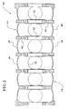
- Figure 2 is a sectional view as taken generally along line II-II of Figure 5 illustrating curved wall portions in the vicinity of the lower portion of the cylinder block;
- Figure 3 is a sectional view as taken generally along line III-III of Figure 5 illustrating curved wall portions in the vicinity of the upper portion of the cylinder block;
- Figure 4 is a sectional view as taken generally along line IV-IV of Figure 3 illustrating one of the reinforcing ribs extending between a respective cylinder bore and the outer wall;
- Figure 5 is a sectional view as taken generally along line V-V of Figure 3 illustrating a closed tappet area generally at the right;
- Figure 6 is a fragmentary sectional view of a cylinder block of Figure 3 as taken generally along line VI-VI, illustrating an embodiment having a closed oil cooler cavity;
- Figure 7 is a graph showing the noise level as measured on the right side of a cylinder block according to the invention (solid line) and a conventional cylinder block (dashed line); and
- Figure 8 is a graph showing the noise level as measured on the left side of a cylinder block according to the invention (solid line) and a conventional cylinder block (dashed line).
- Now referring to the Figures, wherein like numerals designate like parts, Figures 1-6 illustrate a
cylinder block 20 according to an embodiment of the invention. As illustrated in Figure 1, thecylinder block 20 has an integrally formed metal body, including alower portion 22 and anupper portion 24. Theblock 20 has anouter casing 40 which is shared by the upper andlower portions cylindrical parent bores 26 are formed in theblock 20 to accommodate reciprocating pistons (not shown). An inner surface of each of thecylinder bores 26 is precisely machined to a smooth finish. Thelower portion 22 forms a portion of acrankcase 28. An oil pan (not shown) is typically mounted to the lower portion of theblock 20 to enclose the crankcase. - The
upper portion 24 of theblock 20 forms adeck 30 on which a cylinder head (not shown) is to be mounted. As illustrated, theblock 20 is of an in-line six-cylinder configuration, although the features of the invention may be applied to a block having another cylinder configuration as well. - The
cylinder block 20 includes structural features according to the invention which enhance stiffness and which result in reduced noise emission levels by reducing block deflection. The stiffenedblock 20 also results in increased manufacturing efficiency and improved oil-cooling performance. - To provide improved stiffness, the
outer casing 40 of thecylinder block 20 includes curved or sculptedwall portions lower crankcase portion 22 and at theupper portion 24, respectively, as illustrated in Figure 1. More specifically, each of the sculptedwall portions block 20 includes a series of undulate,non-planar wall sections wall section cylindrical wall sections 46 and/or 48, thesections cylinder bores 26. It has been found that thenon-planar wall sections - Referring particularly to Figure 2, the lower sculpted
wall portion 44 of theblock 20 is shown. Thenon-planar wall sections 48 are concave inwardly relative to thecrankcase 28.Transverse support members 50 extend across the interior of thecrankcase 28, and each of thesections 48 extends between a neighboring pair of thesupport members 50. Acrank bearing surface 52 is centrally formed in each of thesupport members 50. - Turning to Figure 3, the
non-planar wall sections 46 of the upper sculptedwall portion 42 are illustrated. On a side of theblock 20 opposite the sculptedwall portion 42, thecasing 40 includes a sculpted closedtappet wall 62. The closedtappet wall 62 is undulate in shape for enhanced stiffness and encloses a plurality oftappet cavities 60 as described in greater detail below in connection with Figure 5. Each of thetappet cavities 60 is generally formed by a tubular member having a curved, non-planarinner wall 66 and a curved, non-planarouter wall section 64 of the sculptedclosed tappet wall 62. Shorter sides 68 integrally connect theinner wall 66 andouter wall section 64. Theouter wall sections 64 and theinner walls 66 are concave in a direction generally facing the cylinder bores 26. - For further enhancing stiffness of the cylinder bores 26, the
upper portion 24 of theblock 20 may include a plurality of stiffeningribs 70 as shown in Figures 3 and 4. Each of theribs 70 extends between the cylinder bores 26 and a cylinderhead bolt boss 72. More particularly, in the illustrated embodiment, theribs 70 are connected to amember 71 formed by material shared by adjacent cylinder bores 26. Theribs 70 also connect thebosses 72 to the sculptedwall portion 46. Theribs 70 are positioned to optimize stiffness of the cylinder bores 26 and to cause any distortion that does occur to be as cylindrical as possible. - Additionally, each of the cylinder
head bolt bosses 72 has abolt hole 74 with threads that extend a greater distance into theblock 20 than conventional bolt holes. Providing such lowered threads has been found to result in an improved load distribution in theblock 20, reducing an amount of contact pressure variation on the gasket ring (not shown) around each of the cylinder bores 26. Specifically, the deep-positioned threads of the invention result in a pressure ratio variation (the ratio between the maximum pressure and minimum pressure) of about 1.6 as compared to a pressure ratio variation of about 3.4 for a conventional block. - As illustrated in Figures 1, 3 and 6, an oil
cooler cavity 80 is formed in a side of thecylinder block 20. The oilcooler cavity 80 is shaped to receive a heat exchanger (not shown) for cooling engine oil. The oilcooler cavity 80 is provided with a flow of coolant, as described below in greater detail. The oilcooler cavity 80 is peripherally defined by fourside walls 82 integrally formed as a side of theblock 20, as illustrated. Theside walls 82 includebolt bosses 84 with bolt holes to accommodate the securing of a cover plate (not shown) with threaded bolts. - The
block 20 has awater jacket 34 providing a passage for a flow of coolant around the cylinder bores 26 (Figures 4, 5). A conventional oil cooler cavity has an entire side that opens directly into the water jacket. According to an embodiment of the invention, however, for further enhancing stiffness, the oilcooler cavity 80 is substantially closed by acavity wall 86 extending between theside walls 82, generally separating thecavity 80 from the water jacket. Thiscavity wall 86 provides structural rigidity to the region of thecavity 80, enhancing the overall stiffness of theblock 20. - Advantageously, the cavity wall also enhances oil-cooling performance. Specifically, the
cavity wall 86 has anopening 88 formed therein to permit fluid communication between thecavity 80 and thewater jacket 34. A water pump outlet 90 (Figure 6) opens into thecavity 80, delivering a flow of coolant from a water pump outlet duct across a core of the oil cooler. According to an embodiment of the invention, theopening 88 is distally located relative to thewater pump outlet 90 so that coolant is advantageously guided to flow across a substantial area of the oil cooler to enhance cooling efficiency. As shown in Figure 6, thewater pump outlet 90 is generally at an upper portion of thecavity 80 while theopening 88 is located generally at a lower portion of thecavity 80. It has been found that thecavity wall 86 of the invention results in a 49% improvement in oil cooling efficiency compared to a conventional open oil cooler cavity. - Figure 5 shows the
closed tappet cavities 60 mentioned above in connection with Figure 3. Each of thetappet areas 60 is enclosed at an outer side by the sculptedclosed tappet wall 62 which is integrally cast with theblock 20. In particular, theblock 20 includes cam bores 94 formed in thetransverse support members 50 positioned in thecrankcase 28. A rotating cam shaft (not shown) is mounted in the cam bores 94, driving a plurality of pivotably-mounted cam followers which cause a plurality of respective pushrods to reciprocate in a generally known manner. The pushrods extend upwardly through theclosed tappet cavity 60 and protrude from theblock 20 through holes 98 (Figure 1) to operate valves in the cylinder head. - As shown in Figure 5, a top of each of the
tappet cavities 60 is also closed by an uppertappet cavity wall 96 which is integrally formed with thecylinder head deck 30. In particular, the uppertappet cavity wall 96 extends across a top of theclosed tappet cavity 60 between the pushrod holes 98 (Figure 1) in thedeck 30; theupper wall 96 being integrally connected to a top edge of the sculpted closedtappet cavity wall 62. The sides and bottom of the sculpted closedtappet cavity wall 62 are integrally connectingblock 20 also between thecavities 60 and along its edges, in addition to being integrally connected at the uppertappet cavity wall 96. Accordingly, thecast wall 62 is sturdy and rigid, minimizing vibration and noise transmission from the moving pushrods, cam followers and other components. Moreover, the sculptedwall 62 provides structural rigidity across the entire side of theblock 20, thereby further enhancing the overall stiffness of theblock 20. Thetappet cavity wall 62 also eliminates the need for a conventional bolt-on cover and associated gasket, reducing a number of engine components. - Due to the enhanced stiffness of the
block 20, it has been found that the conventional practice of torque plate honing is unnecessary. Specifically, the cylinder bores 26 do not deflect substantially between free and loaded conditions, thereby eliminating a need for preloading theblock 20 during machining of the cylinder bores 26. The elimination of this processing step advantageously increases manufacturing efficiency and reduces costs. The stiffenedblock 20 also maintains its close tolerances, resulting in improved oil consumption performance. - The above-described features have been found to enhance the stiffness of the
block 20, resulting in substantially reduced noise levels. Figures 7 and 8 show noise spectrum data as measured from the left and right sides of thecylinder block 20, respectively. In particular, the noise level emitted from the cylinder block of the invention (solid line) is substantially lower than the noise level emitted from a cylinder block having conventional structural features (dashed line). In both Figures 7 and 8, the peak noise level of the conventional cylinder block is approximately 69 dB, whereas the peak noise level of thecylinder block 20 of the invention is about 61 dB. - The present invention is not limited to the exemplary embodiments specifically described herein. To the contrary, it is recognized that various changes and modifications to the embodiments specifically described herein would be apparent to those skilled in the art, and that such changes and modifications may be made without departing from the spirit and scope of the present invention. Accordingly, the appended claims are intended to cover such changes and modifications as well.
Claims (4)
- A cylinder block (20) comprising:- an outer casing (40) generally enclosing a water jacket (34);- a plurality of side walls (82) extending from the outer casing (40) generally defining a cavity (80) shaped to contain an oil cooler;- a water pump outlet (90) disposed in at least one of the side walls (82) to provide a flow of coolant into the cavity (80); and
characterized in that a cavity wall (86) extends between the side walls (82) generally separating the cavity (80) from the water jacket (34); an opening (88) being formed in the cavity wall (86) to permit fluid communication between the cavity (80) and the water jacket (34). - A cylinder block according to claim 1, characterized in that said opening (88) in the cavity wall (86) is distally located relative to the water pump outlet (90).
- A cylinder block according to claim 1 or 2, characterized in that said opening (88) in the cavity wall (86) is generally located at a lower portion of the cavity (80) and said water pump outlet (90) is generally located at an upper portion of the cavity (80).
- A cylinder block according to any of the preceding claims, characterized in that the block (20) further comprises a plurality of bolt bosses (84) formed in said side walls (82), each of the bosses (84) having a bolt hole formed therein to accommodate the securing of a cover plate.
Applications Claiming Priority (2)
| Application Number | Priority Date | Filing Date | Title |
|---|---|---|---|
| GB9813274A GB2338514A (en) | 1998-06-20 | 1998-06-20 | I.c. engine cylinder block with optimizes stiffness |
| EP99201615A EP0965743B1 (en) | 1998-06-20 | 1999-05-21 | Engine cylinder block with optimized stiffness |
Related Parent Applications (1)
| Application Number | Title | Priority Date | Filing Date |
|---|---|---|---|
| EP99201615A Division EP0965743B1 (en) | 1998-06-20 | 1999-05-21 | Engine cylinder block with optimized stiffness |
Publications (2)
| Publication Number | Publication Date |
|---|---|
| EP1632670A2 true EP1632670A2 (en) | 2006-03-08 |
| EP1632670A3 EP1632670A3 (en) | 2009-12-30 |
Family
ID=10834059
Family Applications (3)
| Application Number | Title | Priority Date | Filing Date |
|---|---|---|---|
| EP05111715A Withdrawn EP1632670A3 (en) | 1998-06-20 | 1999-05-21 | Oil cooler cavity |
| EP99201615A Expired - Lifetime EP0965743B1 (en) | 1998-06-20 | 1999-05-21 | Engine cylinder block with optimized stiffness |
| EP05111824A Withdrawn EP1632671A3 (en) | 1998-06-20 | 1999-05-21 | Closed engine tappet cavity. |
Family Applications After (2)
| Application Number | Title | Priority Date | Filing Date |
|---|---|---|---|
| EP99201615A Expired - Lifetime EP0965743B1 (en) | 1998-06-20 | 1999-05-21 | Engine cylinder block with optimized stiffness |
| EP05111824A Withdrawn EP1632671A3 (en) | 1998-06-20 | 1999-05-21 | Closed engine tappet cavity. |
Country Status (5)
| Country | Link |
|---|---|
| US (1) | US6216658B1 (en) |
| EP (3) | EP1632670A3 (en) |
| JP (1) | JP2000064903A (en) |
| DE (1) | DE69930050T2 (en) |
| GB (1) | GB2338514A (en) |
Families Citing this family (22)
| Publication number | Priority date | Publication date | Assignee | Title |
|---|---|---|---|---|
| US6932045B2 (en) * | 2002-05-23 | 2005-08-23 | Daimlerchrysler Ag | Cylinder block for an internal combustion engine |
| KR100444469B1 (en) | 2002-05-28 | 2004-08-16 | 현대자동차주식회사 | Engine structure for intensifying cooling function engine coolant |
| DE102004024516A1 (en) * | 2004-05-18 | 2005-12-15 | Adam Opel Ag | Optimized oil cooling for an internal combustion engine |
| JP4196931B2 (en) * | 2004-10-28 | 2008-12-17 | 三菱自動車工業株式会社 | Crankshaft support structure for internal combustion engines |
| CN102720557A (en) * | 2012-06-27 | 2012-10-10 | 无锡开普动力有限公司 | Oil cooler assembly |
| USD704742S1 (en) * | 2012-09-14 | 2014-05-13 | Honda Motor Co., Ltd | Cylinder block for internal combustion engines |
| USD702260S1 (en) * | 2012-11-29 | 2014-04-08 | Cummins Inc. | Cylinder block |
| USD704744S1 (en) * | 2012-12-19 | 2014-05-13 | Honda Motor Co., Ltd | Cylinder block for internal combustion engines |
| US10190480B2 (en) * | 2013-01-24 | 2019-01-29 | Ford Global Technologies, Llc | Engine cover plate |
| DE102013013646A1 (en) | 2013-08-16 | 2015-02-19 | Daimler Ag | Cylinder housing for a reciprocating internal combustion engine, in particular a motor vehicle |
| USD747670S1 (en) | 2014-07-11 | 2016-01-19 | American Axle & Manufacturing, Inc. | Carrier housing |
| US9517658B2 (en) | 2014-07-11 | 2016-12-13 | American Axle & Manufacturing, Inc. | Axle assembly with carrier housing having increased strength and reduced mass |
| CN104832312B (en) * | 2014-12-01 | 2018-01-19 | 北汽福田汽车股份有限公司 | Cylinder body and engine |
| JP2017180417A (en) * | 2016-03-31 | 2017-10-05 | ヤンマー株式会社 | Engine device |
| JP6473097B2 (en) * | 2016-03-31 | 2019-02-20 | ヤンマー株式会社 | Engine equipment |
| KR102108333B1 (en) * | 2016-03-31 | 2020-05-08 | 얀마 가부시키가이샤 | Engine gear |
| JP6781112B2 (en) * | 2017-06-30 | 2020-11-04 | 株式会社クボタ | Vertical in-line multi-cylinder engine |
| JP7259354B2 (en) * | 2019-01-25 | 2023-04-18 | スズキ株式会社 | Auxiliary equipment support structure for vehicle internal combustion engine |
| USD1008210S1 (en) * | 2021-08-13 | 2023-12-19 | Harman International Industries, Incorporated | Headphone |
| USD1005992S1 (en) * | 2021-12-30 | 2023-11-28 | Harman International Industries, Incorporated | Headphone |
| USD1107757S1 (en) * | 2024-10-16 | 2025-12-30 | Speedway Motors, Inc. | Mock engine block |
| USD1111055S1 (en) * | 2024-10-16 | 2026-02-03 | Speedway Motors, Inc. | Mock engine block |
Family Cites Families (41)
| Publication number | Priority date | Publication date | Assignee | Title |
|---|---|---|---|---|
| US1764739A (en) * | 1928-08-06 | 1930-06-17 | Continental Motors Corp | Internal-combustion engine |
| US2208705A (en) | 1935-06-03 | 1940-07-23 | Soubbotin Igor | Tunnel oven used for the carbonization at low temperatures of oil shale, lignite, coal, and similar materials |
| US2126089A (en) * | 1936-01-09 | 1938-08-09 | Charles S Brown | Internal combustion engine |
| FR1040726A (en) | 1950-04-22 | 1953-10-19 | Gen Motors Corp | Cooling system for internal combustion engines |
| DE1193310B (en) * | 1959-06-20 | 1965-05-20 | Daimler Benz Ag | Lube oil-coolant heat exchanger for internal combustion engines |
| NL277009A (en) | 1961-04-11 | |||
| FR1488629A (en) * | 1966-08-03 | 1967-07-13 | Liberecke Automobilove Zd Y Na | Improvements to the mounting of the lubricating oil heat exchanger in the cooling circuit of an internal combustion engine |
| AT301957B (en) | 1969-09-17 | 1972-09-25 | List Hans | Internal combustion engine with sound-insulating casing |
| DE2621348C2 (en) * | 1976-05-14 | 1984-05-30 | M.A.N. Maschinenfabrik Augsburg-Nürnberg AG, 8500 Nürnberg | Cylinder with dry, thin-walled cylinder liner for internal combustion engines |
| US4175503A (en) * | 1976-12-22 | 1979-11-27 | Ford Motor Company | Method of making air engine housing |
| JPS5392013A (en) | 1977-01-24 | 1978-08-12 | Kubota Ltd | Forced-air cooling v-shaped engine |
| JPS6033311Y2 (en) * | 1978-10-05 | 1985-10-04 | 株式会社小松製作所 | Cylinder block structure for internal combustion engines |
| US4237847A (en) | 1979-03-21 | 1980-12-09 | Cummins Engine Company, Inc. | Composite engine block having high strength to weight ratio |
| DE2913649A1 (en) * | 1979-04-05 | 1980-10-16 | Porsche Ag | Oil cooler for water cooled IC engine - has zigzag heat exchange partition between cooling water and oil in chamber in engine block |
| JPS56110509A (en) | 1980-02-05 | 1981-09-01 | Yanmar Diesel Engine Co Ltd | Air-cooled type internal combustion engine |
| JPS6320847Y2 (en) * | 1980-04-21 | 1988-06-09 | ||
| US4404936A (en) * | 1980-04-30 | 1983-09-20 | Mitsubishi Jukogyo Kabushiki Kaisha | Breather device for overhead valve engines |
| JPS57198338U (en) | 1981-06-11 | 1982-12-16 | ||
| JPS5851246A (en) | 1981-09-21 | 1983-03-25 | Nissan Motor Co Ltd | Cylinder block |
| JPS6049240U (en) * | 1983-09-13 | 1985-04-06 | 日産自動車株式会社 | Cylinder block of boiling-cooled internal combustion engine |
| US4644911A (en) * | 1983-10-07 | 1987-02-24 | Honda Giken Kogyo Kabushiki Kaisha | Cylinder block for internal combustion engine |
| JPS60152047U (en) | 1984-03-21 | 1985-10-09 | マツダ株式会社 | engine cylinder block |
| IT1182082B (en) * | 1984-12-13 | 1987-09-30 | Honda Motor Co Ltd | CYLINDER LOCK STRUCTURE FOR MULTI-CYLINDER INTERNAL COMBUSTION ENGINE |
| DE3633261C1 (en) * | 1986-09-30 | 1987-05-21 | Bayerische Motoren Werke Ag | Cast machine housing for liquid-cooled internal combustion engines with a V-shaped cylinder arrangement |
| JP2568831B2 (en) * | 1987-02-04 | 1997-01-08 | 本田技研工業株式会社 | Water-cooled engine cylinder block |
| JPH01103715U (en) | 1987-12-28 | 1989-07-13 | ||
| DE3807855A1 (en) * | 1988-03-10 | 1989-09-21 | Kloeckner Humboldt Deutz Ag | Internal combustion engine |
| JPH088282Y2 (en) | 1988-04-06 | 1996-03-06 | 日産自動車株式会社 | V type cylinder block for internal combustion engine |
| CA2000353A1 (en) | 1988-10-11 | 1990-04-11 | Tomoyoshi Matsuno | Engine blocks |
| JP2503465Y2 (en) | 1990-03-31 | 1996-07-03 | マツダ株式会社 | Engine block structure |
| DE4029408C2 (en) * | 1990-09-17 | 2003-01-02 | Deutz Ag | Lube oil heat exchanger of an internal combustion engine |
| US5083537A (en) | 1990-12-17 | 1992-01-28 | Ford Motor Company | Composite internal combustion engine housing |
| US5058542A (en) | 1991-01-28 | 1991-10-22 | Briggs & Stratton Corporation | Rocker box cover assembly for internal combustion engine |
| JP2748772B2 (en) * | 1992-05-15 | 1998-05-13 | 株式会社豊田自動織機製作所 | Engine oil cooler |
| US5445210A (en) | 1992-07-17 | 1995-08-29 | Cmi International, Inc. | Casting core for forming cast-in intersecting push rod passages and oil gallery within a cylinder block |
| DE4231284A1 (en) * | 1992-09-18 | 1994-03-24 | Bruehl Eisenwerk | Cylinder block for an internal combustion engine |
| JP3077452B2 (en) | 1993-06-07 | 2000-08-14 | トヨタ自動車株式会社 | Cylinder block for internal combustion engine |
| DE4400952C1 (en) * | 1994-01-14 | 1995-05-24 | Daimler Benz Ag | Housing cover for an internal combustion engine |
| JPH07259555A (en) * | 1994-03-18 | 1995-10-09 | Toyota Motor Corp | Cooling system of internal combustion engine |
| DE19600566C1 (en) | 1996-01-09 | 1997-04-10 | Daimler Benz Ag | Cylinder crank casing for multicylinder internal combustion engine |
| JPH10196451A (en) * | 1997-01-17 | 1998-07-28 | Suzuki Motor Corp | Engine crankcase structure |
-
1998
- 1998-06-20 GB GB9813274A patent/GB2338514A/en not_active Withdrawn
-
1999
- 1999-05-21 EP EP05111715A patent/EP1632670A3/en not_active Withdrawn
- 1999-05-21 EP EP99201615A patent/EP0965743B1/en not_active Expired - Lifetime
- 1999-05-21 EP EP05111824A patent/EP1632671A3/en not_active Withdrawn
- 1999-05-21 DE DE69930050T patent/DE69930050T2/en not_active Expired - Lifetime
- 1999-06-18 US US09/336,105 patent/US6216658B1/en not_active Expired - Lifetime
- 1999-06-18 JP JP11171757A patent/JP2000064903A/en active Pending
Non-Patent Citations (1)
| Title |
|---|
| None * |
Also Published As
| Publication number | Publication date |
|---|---|
| EP1632671A2 (en) | 2006-03-08 |
| EP1632671A3 (en) | 2009-12-30 |
| EP0965743A3 (en) | 2000-11-29 |
| DE69930050D1 (en) | 2006-04-27 |
| US6216658B1 (en) | 2001-04-17 |
| JP2000064903A (en) | 2000-03-03 |
| GB2338514A (en) | 1999-12-22 |
| DE69930050T2 (en) | 2006-08-10 |
| GB9813274D0 (en) | 1998-08-19 |
| EP0965743A2 (en) | 1999-12-22 |
| EP1632670A3 (en) | 2009-12-30 |
| EP0965743B1 (en) | 2006-03-01 |
Similar Documents
| Publication | Publication Date | Title |
|---|---|---|
| EP0965743B1 (en) | Engine cylinder block with optimized stiffness | |
| EP0550422B1 (en) | Cooling system of multi-cylinder engine | |
| EP2187018B1 (en) | Cover secured to engine | |
| US4606304A (en) | One-piece engine block | |
| US5887565A (en) | Lubricating oil passage structure for engine | |
| KR100825366B1 (en) | Cylinder block of engine | |
| US4805563A (en) | Block construction of engine | |
| EP0922849B1 (en) | Cylinder block for an internal combustion engine | |
| US6186111B1 (en) | Support arrangement for the crankcase of a reciprocating piston internal combustion engine | |
| US5662080A (en) | Engine crankcase | |
| US5190003A (en) | Cylinder block for an internal combustion engine | |
| JP4192845B2 (en) | Engine coolant passage structure | |
| EP1314878A2 (en) | Cylinder block for internal combustion engine | |
| JP4262756B2 (en) | Multi-cylinder engine | |
| US5247915A (en) | Cylinder block structure for an internal combustion engine | |
| JP3741799B2 (en) | Oil pump mounting device for engine | |
| EP0677652B1 (en) | Linerless engine cylinder block | |
| US7036479B2 (en) | Cylinder block for engine | |
| EP0064457B1 (en) | Cylinder block of internal combustion engine | |
| EP0476706A1 (en) | Cylinder block structure for an internal combustion engine | |
| CN222350836U (en) | Cylinder block of engine, engine and vehicle | |
| JPH08303295A (en) | Engine cylinder block | |
| JPS6390648A (en) | Cylinder block structure for v-type engine | |
| EP1522704A1 (en) | Cylinder block of internal combustion engine | |
| SU1694964A1 (en) | Internal combustion engine cylinder block |
Legal Events
| Date | Code | Title | Description |
|---|---|---|---|
| PUAI | Public reference made under article 153(3) epc to a published international application that has entered the european phase |
Free format text: ORIGINAL CODE: 0009012 |
|
| AC | Divisional application: reference to earlier application |
Ref document number: 0965743 Country of ref document: EP Kind code of ref document: P |
|
| AK | Designated contracting states |
Kind code of ref document: A2 Designated state(s): AT BE BG CH CY CZ DE DK EE ES FI FR GB GR HU IE IS IT LI LT LU LV MC NL PL PT RO SE SI SK TR |
|
| AX | Request for extension of the european patent |
Extension state: AL BA HR MK YU |
|
| RIN1 | Information on inventor provided before grant (corrected) |
Inventor name: NYDEGGER, HANS-JURG Inventor name: CHIMONIDES, NIKOS JON Inventor name: PIERRO, ENZO |
|
| RIN1 | Information on inventor provided before grant (corrected) |
Inventor name: PIERRO, ENZO Inventor name: NYDEGGER, HANS-JURG Inventor name: CHIMONIDES, NIKOS JON |
|
| PUAL | Search report despatched |
Free format text: ORIGINAL CODE: 0009013 |
|
| AK | Designated contracting states |
Kind code of ref document: A3 Designated state(s): AT BE BG CH CY CZ DE DK EE ES FI FR GB GR HU IE IS IT LI LT LU LV MC NL PL PT RO SE SI SK TR |
|
| AX | Request for extension of the european patent |
Extension state: AL BA HR MK YU |
|
| RIC1 | Information provided on ipc code assigned before grant |
Ipc: F02F 7/00 20060101AFI20051221BHEP Ipc: F02F 1/14 20060101ALI20091123BHEP Ipc: F01P 11/08 20060101ALI20091123BHEP |
|
| 17P | Request for examination filed |
Effective date: 20100630 |
|
| AKX | Designation fees paid |
Designated state(s): DE FR GB IT |
|
| 17Q | First examination report despatched |
Effective date: 20101005 |
|
| STAA | Information on the status of an ep patent application or granted ep patent |
Free format text: STATUS: THE APPLICATION IS DEEMED TO BE WITHDRAWN |
|
| 18D | Application deemed to be withdrawn |
Effective date: 20171212 |