EP1632433A1 - Passenger seat with fabric suspension legrest - Google Patents
Passenger seat with fabric suspension legrest Download PDFInfo
- Publication number
- EP1632433A1 EP1632433A1 EP05021596A EP05021596A EP1632433A1 EP 1632433 A1 EP1632433 A1 EP 1632433A1 EP 05021596 A EP05021596 A EP 05021596A EP 05021596 A EP05021596 A EP 05021596A EP 1632433 A1 EP1632433 A1 EP 1632433A1
- Authority
- EP
- European Patent Office
- Prior art keywords
- seat
- legrest
- seat bottom
- passenger
- fabric
- Prior art date
- Legal status (The legal status is an assumption and is not a legal conclusion. Google has not performed a legal analysis and makes no representation as to the accuracy of the status listed.)
- Granted
Links
- 239000004744 fabric Substances 0.000 title claims abstract description 43
- 239000000725 suspension Substances 0.000 title 1
- 210000002414 leg Anatomy 0.000 claims description 22
- 210000001217 buttock Anatomy 0.000 claims description 7
- 230000003247 decreasing effect Effects 0.000 claims description 3
- 210000003127 knee Anatomy 0.000 claims description 3
- 241001669679 Eleotris Species 0.000 description 4
- 238000000034 method Methods 0.000 description 4
- 239000004677 Nylon Substances 0.000 description 1
- 238000007689 inspection Methods 0.000 description 1
- 239000000463 material Substances 0.000 description 1
- 229920001778 nylon Polymers 0.000 description 1
Images


Classifications
-
- B—PERFORMING OPERATIONS; TRANSPORTING
- B64—AIRCRAFT; AVIATION; COSMONAUTICS
- B64D—EQUIPMENT FOR FITTING IN OR TO AIRCRAFT; FLIGHT SUITS; PARACHUTES; ARRANGEMENT OR MOUNTING OF POWER PLANTS OR PROPULSION TRANSMISSIONS IN AIRCRAFT
- B64D11/00—Passenger or crew accommodation; Flight-deck installations not otherwise provided for
- B64D11/06—Arrangements of seats, or adaptations or details specially adapted for aircraft seats
- B64D11/0639—Arrangements of seats, or adaptations or details specially adapted for aircraft seats with features for adjustment or converting of seats
- B64D11/0643—Adjustable foot or leg rests
-
- B—PERFORMING OPERATIONS; TRANSPORTING
- B60—VEHICLES IN GENERAL
- B60N—SEATS SPECIALLY ADAPTED FOR VEHICLES; VEHICLE PASSENGER ACCOMMODATION NOT OTHERWISE PROVIDED FOR
- B60N2/00—Seats specially adapted for vehicles; Arrangement or mounting of seats in vehicles
- B60N2/90—Details or parts not otherwise provided for
- B60N2/995—Lower-leg-rests, e.g. calf-rests
-
- B—PERFORMING OPERATIONS; TRANSPORTING
- B64—AIRCRAFT; AVIATION; COSMONAUTICS
- B64D—EQUIPMENT FOR FITTING IN OR TO AIRCRAFT; FLIGHT SUITS; PARACHUTES; ARRANGEMENT OR MOUNTING OF POWER PLANTS OR PROPULSION TRANSMISSIONS IN AIRCRAFT
- B64D11/00—Passenger or crew accommodation; Flight-deck installations not otherwise provided for
- B64D11/06—Arrangements of seats, or adaptations or details specially adapted for aircraft seats
- B64D11/0639—Arrangements of seats, or adaptations or details specially adapted for aircraft seats with features for adjustment or converting of seats
- B64D11/064—Adjustable inclination or position of seats
-
- B—PERFORMING OPERATIONS; TRANSPORTING
- B64—AIRCRAFT; AVIATION; COSMONAUTICS
- B64D—EQUIPMENT FOR FITTING IN OR TO AIRCRAFT; FLIGHT SUITS; PARACHUTES; ARRANGEMENT OR MOUNTING OF POWER PLANTS OR PROPULSION TRANSMISSIONS IN AIRCRAFT
- B64D11/00—Passenger or crew accommodation; Flight-deck installations not otherwise provided for
- B64D11/06—Arrangements of seats, or adaptations or details specially adapted for aircraft seats
- B64D11/0639—Arrangements of seats, or adaptations or details specially adapted for aircraft seats with features for adjustment or converting of seats
- B64D11/0641—Seats convertible into beds
Definitions
- This invention relates to a passenger seat, such as is used on public transportation such aircraft, trains and buses.
- the application discloses improvements in the operation of reclinable seats resulting from coordinated movements of the seat back, seat bottom, bolster and leg rest elements.
- a reclinable passenger seat having a seat frame mounting a seat bottom, a seat back extending upwardly from the seat bottom, and a legrest assembly mounted adjacent a forward end of the seat bottom for being selectively extended generally downwardly and outwardly from the seat bottom for supporting the legs of the passenger.
- the legrest assembly comprises a legrest diaphragm mounted for pivotal movement in relation to the seat bottom and a legrest extension diaphragm telescoped within the legrest diaphragm for being selectively extended and retracted relative to the legrest diaphragm to provide an appropriate length leg support for the passenger.
- the first legrest diaphragm and the legrest extension diaphragm each include respective pairs of spaced-apart rails and a fabric attached under tension to the rails for forming a taut, resilient support for the legs of the passenger.
- the fabric comprises a tube, and the rails are positioned within the tube to define a pair of overlaid fabric layers.
- the fabric comprises a tube, and the rails are positioned within the tube to define a pair of overlaid fabric layers.
- the pair of fabric layers of at least the legrest diaphragm are both positioned in closely-spaced apart relation to each other adjacent a top edge of the rails.
- a seat bottom extension assembly is provided for increasing or decreasing the effective length of the seat bottom between the seat back and the leg rest to fit the distance between the buttocks and the back of the knees of the occupant.
- the seat bottom extension assembly comprises a frame for carrying the seat bottom relative to the seat back and for selectively moving the seat bottom relative to the seat back to increase or decrease the length of support provided to the legs of the passenger.
- the seat bottom extension assembly includes an actuator assembly for moving the seat bottom relative to the seat back.
- the rails of the legrest extension each include an inner rail positioned inside the fabric tube to define the depth of the legrest extension and an outer rail positioned on an outer surface of the fabric tube and aligned in a position against the inner rail, trapping two thicknesses of the fabric tube between the inner rail and outer rail to provide a taut, resilient, double layer fabric structure wherein two opposing layers of the fabric tube lie in closely spaced-apart relation to each other in the plane of an upper edge of the inner rail and the outer rail.
- a passenger seat having a seat frame mounting a seat bottom, a seat back extending upwardly from the seat bottom, and a legrest assembly mounted adjacent a forward end of the seat bottom for being selectively extended generally downwardly and outwardly from the seat bottom for supporting the legs of the passenger, the improvement comprising moving the seat bottom and legrest assembly relative to the seat back for increasing the effective length of support to the buttocks and legs of the passenger.
- FIG. 1 a passenger seat according to the present invention is illustrated in Figure 1 and shown generally at reference numeral 10.
- the passenger seat 10 includes a seat frame 11 which is attached to a track 13 mounted on the deck of an airplane. Attachment is made by use of track fittings, such as those disclosed in applicant's U,S. Patent Nos. 5,169,091, 5,178,346 or 5,861,318.
- the seat frame 11 includes horizontally spaced spreaders 12 which include seat pan articulation slots 18.
- the seat back 15 is attached to the seat frame 11 at back pivot location 16 and to the seat pan 19 at seat pan pivot 17.
- the seat pan 19 is attached to the seat frame spreaders 12 at the seat pan articulation slot 18.
- the legrest 21 is attached to the seat pan 19 at legrest pivot 20.
- a footrest 22 extends out of legrest 21.
- the seat endbay and consoles 14 bound the occupant on each side.
- the seat 10 is capable of articulating into several positions.
- the seat back articulation occurs by rotation about seat back pivot 17.
- Seat back articulation drives the seat pan 19 by seat pan pivot 17 and seat pan articulation slot 18.
- the seat pan 19 also includes seat pan extension 24 which raises and lowers an extra support cushion 28 via slots included in the frame of seat pan 19.
- Legrest articulation 26 is possible by pivoting about legrest pivot 20.
- Legrest extension 25 is also possible by extending footrest 22 via a slide mechanism.
- the legrest 21 and footrest 22 support surfaces consist of a fabric diaphragm suspended between frame supports on each side. The footrest 22 slides into and out of the end of legrest 21.
- the seat pan 19 includes a seat pan diaphragm 31 attached between two seat pan rails 32 and an additional extra support cushion 28 which can be articulated fore/aft by movement of the seat pan extension rail 33.
- extra support cushion 28 articulates upward in extra support cushion articulation slot 30.
- Overall positioning of the seat pan 19 is driven by the location of seat pan pivots 17 which are connected to seat back 15, and by the location of cam followers 29, which move inside seat pan articulation slot 18.
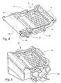
- legrest assembly 21 consists of a legrest diaphragm 34 suspended between legrest support rails 38 and an additional legrest extension diaphragm 35 suspended between footrest rails 39.
- Footrest 36 is attached at the end of legrest extension rails 39.
- Legrest 21 ( Figure 1) is connected to seat pan extension rail 33 ( Figure 4) and rotates about legrest pivot location 39.
- Legrest extension rails 39 slide in and out between legrest support rails 38, which provide additional leg clearance for taller passengers.
- Footrest 36 is attached to legrest extension rails 39 at the footrest pivots 37 and rotates as shown in Figure 5 to provide support for the passengers feet.
- the support cushion 28 extends outwardly from the front end of the seat pan 19 as the seat 10 is progressively reclined.
- a pin 18A captured in seat pan articulation slot 18 controls movement of the seat pan 19 as the seat 10 is articulated.
- legrest diaphragm 34 and the legrest extension diaphragm 35 telescope to lengthen or shorten the overall length of the legrest 21 as desired by the passenger.
- the legrest extension diaphragm 35 is nested within the legrest diaphragm 34.
- the legrest diaphragm 34 is assembled by forming a fabric tube 50(Figure 13A) and positioning two inner rails 51, 52 therein whereby the tube is maintained in an open condition and gives a specified depth to the tube 50 ( Figure 13B).
- a second pair of outer rails 53, 54 ( Figure 13C) is then positioned on the outside of the tube 50 adjacent the inner rails 51, 52 ( Figure 13D) and pressed upwardly and into alignment with the inner rails 51, 52, as shown in Figure 13E.
- This movement stretches the fabric and provides a taut, resilient double-layer support for the upper legs of the passenger.
- Suitable fasteners 56 secure the fabric tube in position between the pairs of rails 51, 52, 53, 54, respectively.
- the fabric may be a material made by DuPont and sold under the trademark Dymetrol 200, a dense, nylon-based fabric, a unidirectional fabric sold under the trademark Crystal Flex, or any other suitable fabric. Characteristics important in fabric selection include strength, resiliency, wear resistance and resistance to soiling.
- FIGs 14A-14C illustrate in simplified form the articulation of the seat 10, including the rearward movement of the seat back 15, the forward movement of the seat pan 19 and the extension of the legrest 21.
- the seat back 15 is moved by pivotal movement about the back pivot 16.
- the back of the seat pan 19 is pivoted about the pivot 17.
- the forward end of the seat pan is translated between the positions shown in Figures 14A-14C by movement of pivot pin 18A in slot 18.
- the curve in the slot 18 provides a slight upward movement to the forward end of the seat pan 19 in the recline position (See Figures 2 and 14B) which prevents the passenger from slipping down the seat.
- the seat pan 19 is lowered slightly to more closely align the body of the passenger in a true prone sleeping position. (See Figures 3 and 14C).
- the seat may be powered by any suitable drive device, such as pneumatic cylinders, a motor-driven worm drive or other types electric motors.
- the reclinable passenger seat may have a seat frame mounting a seat bottom, a seat back extending upwardly from the seat bottom, and a legrest assembly mounted adjacent a forward end of the seat bottom for being selectively extended generally downwardly and outwardly from the seat bottom for supporting the legs of the passenger, said legrest assembly comprising:
- the fabric may comprise a tube, and wherein said rails are positioned within said tube to define a pair of overlaid fabric layers.
- the fabric may comprise a tube, and wherein said rails are positioned within said tube to define a pair of overlaid fabric layers, and a further wherein said pair of fabric layers of at least the legrest diaphragm are both positioned in closely-spaced apart relation to each other adjacent a top edge of said rails.
- the seat may include a seat bottom extension assembly for increasing or decreasing the effective length of the seat bottom between the seat back and the legrest to fit the distance between the buttocks and the back of the knees of the occupant.
- the seat bottom extension assembly may comprise a frame for carrying the seat bottom relative to the seat back and for selectively moving the seat bottom relative to the seat back to increase or decrease the length of support provided to the legs of the passenger.
- the seat bottom extension assembly may include an actuator assembly for moving the seat bottom relative to said seat back.
- the rails of the legrest extension may each include an inner rail positioned inside the fabric tube to define the depth of the legrest extension and an outer rail positioned on an outer surface of the fabric tube and aligned in a position against the inner rail, trapping two thicknesses of the fabric tube between the inner rail and outer rail to provide a taut, resilient, double layer fabric structure wherein two opposing layers of the fabric tube lie in closely spaced-apart relation to each other in the plane of an upper edge of the inner rail and the outer rail.
- a reclinable passenger seat may have a seat frame mounting a seat bottom, a seat back extending upwardly from the seat bottom, and a legrest assembly mounted adjacent a forward end of the seat bottom for being selectively extended generally downwardly and outwardly from the seat bottom for supporting the legs of the passenger, the improvement comprising moving the seat bottom and legrest assembly relative to the seat back for increasing the effective length of support to the buttocks and legs of the passenger.
Landscapes
- Engineering & Computer Science (AREA)
- Aviation & Aerospace Engineering (AREA)
- Transportation (AREA)
- Mechanical Engineering (AREA)
- Chairs For Special Purposes, Such As Reclining Chairs (AREA)
- Passenger Equipment (AREA)
Abstract
Description
- The application claims priority from Provisional Patent Application Serial No. 60/176,365, filed January 14, 2000.
- This invention relates to a passenger seat, such as is used on public transportation such aircraft, trains and buses. The application discloses improvements in the operation of reclinable seats resulting from coordinated movements of the seat back, seat bottom, bolster and leg rest elements.
- It is an object of the invention to provide a passenger seat which is comfortable.
- It is another object of the invention to provide a passenger seat which is durable.
- It is another object of the invention to provide a passenger seat which is easily and quickly repaired or replaced as needed.
- It is another object of the invention to provide a passenger seat which is lightweight.
- It is another object of the invention to provide a passenger seat which is extensible.
- These and other objects of the present invention are achieved in the preferred embodiments disclosed below by providing a reclinable passenger seat having a seat frame mounting a seat bottom, a seat back extending upwardly from the seat bottom, and a legrest assembly mounted adjacent a forward end of the seat bottom for being selectively extended generally downwardly and outwardly from the seat bottom for supporting the legs of the passenger. The legrest assembly comprises a legrest diaphragm mounted for pivotal movement in relation to the seat bottom and a legrest extension diaphragm telescoped within the legrest diaphragm for being selectively extended and retracted relative to the legrest diaphragm to provide an appropriate length leg support for the passenger. The first legrest diaphragm and the legrest extension diaphragm each include respective pairs of spaced-apart rails and a fabric attached under tension to the rails for forming a taut, resilient support for the legs of the passenger.
- According to one preferred embodiment of the invention, the fabric comprises a tube, and the rails are positioned within the tube to define a pair of overlaid fabric layers.
- According to another preferred embodiment of the invention, the fabric comprises a tube, and the rails are positioned within the tube to define a pair of overlaid fabric layers. The pair of fabric layers of at least the legrest diaphragm are both positioned in closely-spaced apart relation to each other adjacent a top edge of the rails.
- According to yet another preferred embodiment of the invention, a seat bottom extension assembly is provided for increasing or decreasing the effective length of the seat bottom between the seat back and the leg rest to fit the distance between the buttocks and the back of the knees of the occupant.
- According to yet another preferred embodiment of the invention, the seat bottom extension assembly comprises a frame for carrying the seat bottom relative to the seat back and for selectively moving the seat bottom relative to the seat back to increase or decrease the length of support provided to the legs of the passenger.
- According to yet another preferred embodiment of the invention, the seat bottom extension assembly includes an actuator assembly for moving the seat bottom relative to the seat back.
- According to yet another preferred embodiment of the invention, the rails of the legrest extension each include an inner rail positioned inside the fabric tube to define the depth of the legrest extension and an outer rail positioned on an outer surface of the fabric tube and aligned in a position against the inner rail, trapping two thicknesses of the fabric tube between the inner rail and outer rail to provide a taut, resilient, double layer fabric structure wherein two opposing layers of the fabric tube lie in closely spaced-apart relation to each other in the plane of an upper edge of the inner rail and the outer rail.
- According to yet another preferred embodiment of the invention, a passenger seat is provided having a seat frame mounting a seat bottom, a seat back extending upwardly from the seat bottom, and a legrest assembly mounted adjacent a forward end of the seat bottom for being selectively extended generally downwardly and outwardly from the seat bottom for supporting the legs of the passenger, the improvement comprising moving the seat bottom and legrest assembly relative to the seat back for increasing the effective length of support to the buttocks and legs of the passenger.
- Some of the objects of the invention have been set forth above. Other objects and advantages of the invention will appear as the invention proceeds when taken in conjunction with the following drawings, in which:
- Figure 1 is a vertical cross-sectional view of a passenger seat according to one embodiment of the invention in a takeoff and landing position;
- Figure 2 is a vertical cross-sectional view of the passenger seat of Figure 1 in a recline position;
- Figure 3 is a vertical cross-sectional view of a passenger seat of Figure 1 in a sleeper position;
- Figure 4 is a fragmentary view of the seat pan of the seat shown in Figure 1 in a recline position;
- Figure 5 is a fragmentary view of the seat pan of the seat shown in Figure 1 in a landing and takeoff position;
- Figure 6 is a view of the legrest and footrest portion of the passenger seat shown in Figure 1;
- Figure 7 is a view of the legrest and footrest in the landing and takeoff position;
- Figure 8 is a view of the legrest and footrest in the recline position;
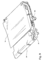
- Figure 9 is a view of the legrest and footrest in the sleeper position;
- Figure 10 is a fragmentary view of the seat pan articulation slot in the landing and takeoff position;
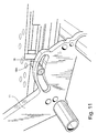
- Figure 11 is a fragmentary view of the seat pan articulation slot in the recline position;
- Figure 12 is a fragmentary view of the seat shown in Figure 1, showing the extension of the legrest;
- Figures 13A-13E are fragmentary views showing the assembly of the fabric legrest; and
- Figures 14A-14C are simplified vertical cross-sections of the seat shown in Figure 1 in the landing/takeoff, recline and sleeper positions.
- Referring now specifically to the drawings, a passenger seat according to the present invention is illustrated in Figure 1 and shown generally at
reference numeral 10. - The
passenger seat 10 includes aseat frame 11 which is attached to atrack 13 mounted on the deck of an airplane. Attachment is made by use of track fittings, such as those disclosed in applicant's U,S. Patent Nos. 5,169,091, 5,178,346 or 5,861,318. Theseat frame 11 includes horizontally spacedspreaders 12 which include seatpan articulation slots 18. Theseat back 15 is attached to theseat frame 11 atback pivot location 16 and to theseat pan 19 atseat pan pivot 17. Theseat pan 19 is attached to theseat frame spreaders 12 at the seatpan articulation slot 18. Thelegrest 21 is attached to theseat pan 19 atlegrest pivot 20. Afootrest 22 extends out oflegrest 21. The seat endbay andconsoles 14 bound the occupant on each side. - As shown in Figure 2, the
seat 10 is capable of articulating into several positions. The seat back articulation occurs by rotation aboutseat back pivot 17. Seat back articulation drives theseat pan 19 byseat pan pivot 17 and seatpan articulation slot 18. As the seat pan articulates, the position and angle of the seat pan is controlled by the location of theseat pan pivot 17 and theseat pan 19 within the seatpan articulation slot 18. Theseat pan 19 also includesseat pan extension 24 which raises and lowers anextra support cushion 28 via slots included in the frame ofseat pan 19.Legrest articulation 26 is possible by pivoting aboutlegrest pivot 20. Legrestextension 25 is also possible by extendingfootrest 22 via a slide mechanism. Thelegrest 21 andfootrest 22 support surfaces consist of a fabric diaphragm suspended between frame supports on each side. Thefootrest 22 slides into and out of the end oflegrest 21. - Referring to Figures 4 and 5, the
seat pan 19 includes aseat pan diaphragm 31 attached between twoseat pan rails 32 and an additionalextra support cushion 28 which can be articulated fore/aft by movement of the seatpan extension rail 33. Upon fore/aft movement of the seat pan extension rail,extra support cushion 28 articulates upward in extra supportcushion articulation slot 30. Overall positioning of theseat pan 19 is driven by the location ofseat pan pivots 17 which are connected to seat back 15, and by the location ofcam followers 29, which move inside seatpan articulation slot 18. - Referring to Figure 6,
legrest assembly 21 consists of alegrest diaphragm 34 suspended betweenlegrest support rails 38 and an additionallegrest extension diaphragm 35 suspended betweenfootrest rails 39. Footrest 36 is attached at the end oflegrest extension rails 39. Legrest 21 (Figure 1) is connected to seat pan extension rail 33 (Figure 4) and rotates aboutlegrest pivot location 39. Legrestextension rails 39 slide in and out betweenlegrest support rails 38, which provide additional leg clearance for taller passengers. Footrest 36 is attached to legrest extension rails 39 at the footrest pivots 37 and rotates as shown in Figure 5 to provide support for the passengers feet. - As is shown in Figures 7, 8 and 9, the
support cushion 28 extends outwardly from the front end of theseat pan 19 as theseat 10 is progressively reclined. - As is shown in Figures 10 and 11, a
pin 18A captured in seatpan articulation slot 18 controls movement of theseat pan 19 as theseat 10 is articulated. - Referring now to Figure 12, the
legrest diaphragm 34 and thelegrest extension diaphragm 35 telescope to lengthen or shorten the overall length of thelegrest 21 as desired by the passenger. Thelegrest extension diaphragm 35 is nested within thelegrest diaphragm 34. - Referring now to Figures 13A-E, the
legrest diaphragm 34 is assembled by forming a fabric tube 50(Figure 13A) and positioning twoinner rails outer rails 53, 54 (Figure 13C) is then positioned on the outside of thetube 50 adjacent theinner rails 51, 52 (Figure 13D) and pressed upwardly and into alignment with theinner rails Suitable fasteners 56 secure the fabric tube in position between the pairs ofrails - The fabric may be a material made by DuPont and sold under the trademark Dymetrol 200, a dense, nylon-based fabric, a unidirectional fabric sold under the trademark Crystal Flex, or any other suitable fabric. Characteristics important in fabric selection include strength, resiliency, wear resistance and resistance to soiling.
- Figures 14A-14C illustrate in simplified form the articulation of the
seat 10, including the rearward movement of the seat back 15, the forward movement of theseat pan 19 and the extension of thelegrest 21. As shown, the seat back 15 is moved by pivotal movement about theback pivot 16. The back of theseat pan 19 is pivoted about thepivot 17. The forward end of the seat pan is translated between the positions shown in Figures 14A-14C by movement ofpivot pin 18A inslot 18. The curve in theslot 18 provides a slight upward movement to the forward end of theseat pan 19 in the recline position (See Figures 2 and 14B) which prevents the passenger from slipping down the seat. In the sleeper position, theseat pan 19 is lowered slightly to more closely align the body of the passenger in a true prone sleeping position. (See Figures 3 and 14C). - The seat may be powered by any suitable drive device, such as pneumatic cylinders, a motor-driven worm drive or other types electric motors.
- The reader's attention is directed to all papers and documents which are filed concurrently with or previous to this specification in connection with this application and which are open to public inspection with this specification, and the contents of all such papers and documents are incorporated herein by reference.
- All of the features disclosed in this specification (including any accompanying claims, abstract and drawings), and/or all of the steps of any method or process so disclosed, may be combined in any combination, except combinations where at least some of such features and/or steps are mutually exclusive.
- Each feature disclosed in this specification (including any accompanying claims, abstract and drawings), may be replaced by alternative features serving the same, equivalent or similar purpose, unless expressly stated otherwise. Thus, unless expressly stated otherwise, each feature disclosed is one example only of a generic series of equivalent or similar features.
- The invention is not restricted to the details of the foregoing embodiment(s). The invention extend to any novel one, or any novel combination, of the features disclosed in this specification (including any accompanying claims, abstract and drawings), or to any novel one, or any novel combination, of the steps of any method or process so disclosed.
- The reclinable passenger seat may have a seat frame mounting a seat bottom, a seat back extending upwardly from the seat bottom, and a legrest assembly mounted adjacent a forward end of the seat bottom for being selectively extended generally downwardly and outwardly from the seat bottom for supporting the legs of the passenger, said legrest assembly comprising:
- (a) a legrest diaphragm mounted for pivotal movement in relation to the seat bottom;
- (b) a legrest extension diaphragm telescoped within said legrest diaphragm for being selectively extended and retracted relative to said legrest diaphragm to provide an appropriate length leg support for the passenger; and
- (c) said legrest diaphragm and said legrest extension diaphragm each including respective pairs of spaced-apart rails and a fabric attached under tension to said rails for forming between the rails a taut, resilient support for the legs of the passenger.
- The fabric may comprise a tube, and wherein said rails are positioned within said tube to define a pair of overlaid fabric layers.
- The fabric may comprise a tube, and wherein said rails are positioned within said tube to define a pair of overlaid fabric layers, and a further wherein said pair of fabric layers of at least the legrest diaphragm are both positioned in closely-spaced apart relation to each other adjacent a top edge of said rails.
- The seat may include a seat bottom extension assembly for increasing or decreasing the effective length of the seat bottom between the seat back and the legrest to fit the distance between the buttocks and the back of the knees of the occupant.
- The seat bottom extension assembly may comprise a frame for carrying the seat bottom relative to the seat back and for selectively moving the seat bottom relative to the seat back to increase or decrease the length of support provided to the legs of the passenger.
- The seat bottom extension assembly may include an actuator assembly for moving the seat bottom relative to said seat back.
- The rails of the legrest extension may each include an inner rail positioned inside the fabric tube to define the depth of the legrest extension and an outer rail positioned on an outer surface of the fabric tube and aligned in a position against the inner rail, trapping two thicknesses of the fabric tube between the inner rail and outer rail to provide a taut, resilient, double layer fabric structure wherein two opposing layers of the fabric tube lie in closely spaced-apart relation to each other in the plane of an upper edge of the inner rail and the outer rail.
- A reclinable passenger seat may have a seat frame mounting a seat bottom, a seat back extending upwardly from the seat bottom, and a legrest assembly mounted adjacent a forward end of the seat bottom for being selectively extended generally downwardly and outwardly from the seat bottom for supporting the legs of the passenger, the improvement comprising moving the seat bottom and legrest assembly relative to the seat back for increasing the effective length of support to the buttocks and legs of the passenger.
Claims (8)
- In a reclinable passenger seat having a seat frame mounting a seat bottom, a seat back extending upwardly from the seat bottom, and a legrest assembly mounted adjacent a forward end of the seat bottom for being selectively extended generally downwardly and outwardly from the seat bottom for supporting the legs of the passenger, the improvement comprising moving the seat bottom and legrest assembly relative to the seat back for increasing the effective length of support to the buttocks and legs of the passenger.
- A reclinable passenger seat according to claim 1, wherein said fabric comprises a tube, and wherein said rails are positioned within said tube to define a pair of overlaid fabric layers.
- A reclinable passenger seat according to claim 1, wherein said fabric comprises a tube, and wherein said rails are positioned within said tube to define a pair of overlaid fabriclayers, and further wherein said pair of fabric layers of at least the legrest diaphragm are both positioned in closely-spaced apart relation to each other adjacent a top edge of said rails.
- A reclinable passenger seat according to claim 1, 2 or 3, and including a seat bottom extension assembly for increasing or decreasing the effective length of the seat bottom between the seat back and the leg rest to fit the distance between the buttocks and the back of the knees of the occupant.
- A reclinable passenger seat according to claim 4, wherein said seat bottom extension assembly comprises a frame for carrying the seat bottom relative to the seat back and for selectively moving the seat bottom relative to the seat back to increase or decrease the length of support provided to the legs of the passenger.
- A reclinable passenger seat according to claim 5, wherein said seat bottom extension assembly includes an actuator assembly for moving the seat bottom relative to said seat back.
- A reclinable passenger seat according to claim 1, wherein the rails of the legrest extension each include an inner rail positioned inside the fabric tube to define the depth of the legrest extension and an outer rail positioned on an outer surface of the fabric tube and aligned in a position against the inner rail, trapping two thicknesses of the fabric tube between the inner rail and outer rail to provide a taut, resilient, double layer fabric structure wherein two opposing layers of the fabric tube lie in closely spaced-apart relation to each other in the plane of an upper edge of the inner rail and the outer rail.
- In a reclinable passenger seat having a seat frame mounting a seat bottom, a seat back extending upwardly from the seat bottom, and a legrest assembly mounted adjacent a forward end of the seat bottom for being selectively extended generally downwardly and outwardly from the seat bottom for supporting the legs of the passenger, the improvement comprising moving the seat bottom and legrest assembly relative to the seat back for increasing the effective length of support to the buttocks and legs of the passenger.
Applications Claiming Priority (2)
| Application Number | Priority Date | Filing Date | Title |
|---|---|---|---|
| US17636500P | 2000-01-14 | 2000-01-14 | |
| EP01300231A EP1116653B1 (en) | 2000-01-14 | 2001-01-11 | Passenger seat with fabric suspension legrest |
Related Parent Applications (1)
| Application Number | Title | Priority Date | Filing Date |
|---|---|---|---|
| EP01300231A Division EP1116653B1 (en) | 2000-01-14 | 2001-01-11 | Passenger seat with fabric suspension legrest |
Publications (2)
| Publication Number | Publication Date |
|---|---|
| EP1632433A1 true EP1632433A1 (en) | 2006-03-08 |
| EP1632433B1 EP1632433B1 (en) | 2012-10-10 |
Family
ID=35809939
Family Applications (1)
| Application Number | Title | Priority Date | Filing Date |
|---|---|---|---|
| EP05021596A Expired - Lifetime EP1632433B1 (en) | 2000-01-14 | 2001-01-11 | Passenger seat with fabric suspension legrest |
Country Status (1)
| Country | Link |
|---|---|
| EP (1) | EP1632433B1 (en) |
Cited By (1)
| Publication number | Priority date | Publication date | Assignee | Title |
|---|---|---|---|---|
| EP3031724A1 (en) * | 2014-12-08 | 2016-06-15 | Volvo Car Corporation | A reclinable seat |
Citations (7)
| Publication number | Priority date | Publication date | Assignee | Title |
|---|---|---|---|---|
| US5169091A (en) | 1991-07-12 | 1992-12-08 | Beroth Michael T | Track fastener apparatus and assembly |
| US5178346A (en) | 1991-07-12 | 1993-01-12 | Burns Aerospace Corporation | Track fastener apparatus and assembly |
| WO1996018537A1 (en) * | 1994-12-13 | 1996-06-20 | British Airways Plc | A seating unit |
| US5560681A (en) | 1995-03-21 | 1996-10-01 | Burns Aerospace Corporation | Seat bottom extension mechanism for passenger seats |
| EP0869060A1 (en) | 1997-02-20 | 1998-10-07 | Singapore Airlines Limited | Improvements in transport accommodation |
| US5861318A (en) | 1994-11-16 | 1999-01-19 | Pharmacia & Upjohn Company | Scintillation proximity assay for N-acetylgalactosaminyltransferase activity |
| EP1116654A2 (en) * | 2000-01-13 | 2001-07-18 | Be Aerospace, Inc. | Passenger sleeper seat |
-
2001
- 2001-01-11 EP EP05021596A patent/EP1632433B1/en not_active Expired - Lifetime
Patent Citations (7)
| Publication number | Priority date | Publication date | Assignee | Title |
|---|---|---|---|---|
| US5169091A (en) | 1991-07-12 | 1992-12-08 | Beroth Michael T | Track fastener apparatus and assembly |
| US5178346A (en) | 1991-07-12 | 1993-01-12 | Burns Aerospace Corporation | Track fastener apparatus and assembly |
| US5861318A (en) | 1994-11-16 | 1999-01-19 | Pharmacia & Upjohn Company | Scintillation proximity assay for N-acetylgalactosaminyltransferase activity |
| WO1996018537A1 (en) * | 1994-12-13 | 1996-06-20 | British Airways Plc | A seating unit |
| US5560681A (en) | 1995-03-21 | 1996-10-01 | Burns Aerospace Corporation | Seat bottom extension mechanism for passenger seats |
| EP0869060A1 (en) | 1997-02-20 | 1998-10-07 | Singapore Airlines Limited | Improvements in transport accommodation |
| EP1116654A2 (en) * | 2000-01-13 | 2001-07-18 | Be Aerospace, Inc. | Passenger sleeper seat |
Cited By (2)
| Publication number | Priority date | Publication date | Assignee | Title |
|---|---|---|---|---|
| EP3031724A1 (en) * | 2014-12-08 | 2016-06-15 | Volvo Car Corporation | A reclinable seat |
| US9981569B2 (en) | 2014-12-08 | 2018-05-29 | Volvo Car Corporation | Reclinable seat |
Also Published As
| Publication number | Publication date |
|---|---|
| EP1632433B1 (en) | 2012-10-10 |
Similar Documents
| Publication | Publication Date | Title |
|---|---|---|
| EP1116653B1 (en) | Passenger seat with fabric suspension legrest | |
| US6494536B2 (en) | Passenger seat with variable length seat bottom | |
| AU2017435057B2 (en) | Aircraft seat | |
| EP1390228B1 (en) | Adjustable seats | |
| US5628547A (en) | Passenger seat | |
| EP3519243B1 (en) | Aircraft passenger seat assembly including a backrest tilt apparatus | |
| CN105916768B (en) | airplane couch that converts into a bed | |
| EP2729365B1 (en) | Seat pan assembly | |
| US7341309B2 (en) | Passenger seating with variable length seat bottom | |
| EP1116654A2 (en) | Passenger sleeper seat | |
| US20030111888A1 (en) | Vehicle passenger seat | |
| CN111572780B (en) | Multi-position adjustable headrest assembly | |
| WO2010005678A2 (en) | Articulating passenger seat | |
| EP2646319A1 (en) | Aircraft seat | |
| EP3512771B1 (en) | Aircraft seat | |
| CN207737150U (en) | A kind of seat and seat leg support | |
| EP3670250B1 (en) | Transformable seat assembly | |
| US10864992B2 (en) | Transformable seat assembly | |
| EP1632433A1 (en) | Passenger seat with fabric suspension legrest | |
| CN109130966A (en) | Seat and vehicle with release lever | |
| US11352143B2 (en) | Transformable seat assembly | |
| CN222859265U (en) | Zero-gravity seat with single drive mechanism and vehicle thereof | |
| US11180256B2 (en) | Transformable seat assembly | |
| US11059588B2 (en) | Transformable seat assembly | |
| GB2619723A (en) | Passenger seat assembly for an aircraft |
Legal Events
| Date | Code | Title | Description |
|---|---|---|---|
| PUAI | Public reference made under article 153(3) epc to a published international application that has entered the european phase |
Free format text: ORIGINAL CODE: 0009012 |
|
| 17P | Request for examination filed |
Effective date: 20051004 |
|
| AC | Divisional application: reference to earlier application |
Ref document number: 1116653 Country of ref document: EP Kind code of ref document: P |
|
| AK | Designated contracting states |
Kind code of ref document: A1 Designated state(s): AT BE CH CY DE DK ES FI FR GB GR IE IT LI LU MC NL PT SE TR |
|
| AKX | Designation fees paid |
Designated state(s): DE FR GB IT |
|
| GRAP | Despatch of communication of intention to grant a patent |
Free format text: ORIGINAL CODE: EPIDOSNIGR1 |
|
| GRAS | Grant fee paid |
Free format text: ORIGINAL CODE: EPIDOSNIGR3 |
|
| GRAA | (expected) grant |
Free format text: ORIGINAL CODE: 0009210 |
|
| AC | Divisional application: reference to earlier application |
Ref document number: 1116653 Country of ref document: EP Kind code of ref document: P |
|
| AK | Designated contracting states |
Kind code of ref document: B1 Designated state(s): DE FR GB IT |
|
| REG | Reference to a national code |
Ref country code: GB Ref legal event code: FG4D |
|
| REG | Reference to a national code |
Ref country code: DE Ref legal event code: R096 Ref document number: 60147217 Country of ref document: DE Effective date: 20121206 |
|
| PLBE | No opposition filed within time limit |
Free format text: ORIGINAL CODE: 0009261 |
|
| STAA | Information on the status of an ep patent application or granted ep patent |
Free format text: STATUS: NO OPPOSITION FILED WITHIN TIME LIMIT |
|
| 26N | No opposition filed |
Effective date: 20130711 |
|
| REG | Reference to a national code |
Ref country code: DE Ref legal event code: R097 Ref document number: 60147217 Country of ref document: DE Effective date: 20130711 |
|
| REG | Reference to a national code |
Ref country code: FR Ref legal event code: PLFP Year of fee payment: 16 |
|
| REG | Reference to a national code |
Ref country code: FR Ref legal event code: PLFP Year of fee payment: 17 |
|
| REG | Reference to a national code |
Ref country code: FR Ref legal event code: PLFP Year of fee payment: 18 |
|
| PGFP | Annual fee paid to national office [announced via postgrant information from national office to epo] |
Ref country code: GB Payment date: 20200127 Year of fee payment: 20 Ref country code: IT Payment date: 20200123 Year of fee payment: 20 Ref country code: DE Payment date: 20200129 Year of fee payment: 20 |
|
| PGFP | Annual fee paid to national office [announced via postgrant information from national office to epo] |
Ref country code: FR Payment date: 20200127 Year of fee payment: 20 |
|
| REG | Reference to a national code |
Ref country code: DE Ref legal event code: R071 Ref document number: 60147217 Country of ref document: DE |
|
| REG | Reference to a national code |
Ref country code: GB Ref legal event code: PE20 Expiry date: 20210110 |
|
| PG25 | Lapsed in a contracting state [announced via postgrant information from national office to epo] |
Ref country code: GB Free format text: LAPSE BECAUSE OF EXPIRATION OF PROTECTION Effective date: 20210110 |