EP1632418A2 - Controlled energy absorption for a steering column depending on its tilt and telescope positions - Google Patents
Controlled energy absorption for a steering column depending on its tilt and telescope positions Download PDFInfo
- Publication number
- EP1632418A2 EP1632418A2 EP05076978A EP05076978A EP1632418A2 EP 1632418 A2 EP1632418 A2 EP 1632418A2 EP 05076978 A EP05076978 A EP 05076978A EP 05076978 A EP05076978 A EP 05076978A EP 1632418 A2 EP1632418 A2 EP 1632418A2
- Authority
- EP
- European Patent Office
- Prior art keywords
- steering column
- column member
- along
- path
- tilt
- Prior art date
- Legal status (The legal status is an assumption and is not a legal conclusion. Google has not performed a legal analysis and makes no representation as to the accuracy of the status listed.)
- Granted
Links
Images

Classifications
-
- B—PERFORMING OPERATIONS; TRANSPORTING
- B62—LAND VEHICLES FOR TRAVELLING OTHERWISE THAN ON RAILS
- B62D—MOTOR VEHICLES; TRAILERS
- B62D1/00—Steering controls, i.e. means for initiating a change of direction of the vehicle
- B62D1/02—Steering controls, i.e. means for initiating a change of direction of the vehicle vehicle-mounted
- B62D1/16—Steering columns
- B62D1/18—Steering columns yieldable or adjustable, e.g. tiltable
- B62D1/187—Steering columns yieldable or adjustable, e.g. tiltable with tilt adjustment; with tilt and axial adjustment
-
- B—PERFORMING OPERATIONS; TRANSPORTING
- B62—LAND VEHICLES FOR TRAVELLING OTHERWISE THAN ON RAILS
- B62D—MOTOR VEHICLES; TRAILERS
- B62D1/00—Steering controls, i.e. means for initiating a change of direction of the vehicle
- B62D1/02—Steering controls, i.e. means for initiating a change of direction of the vehicle vehicle-mounted
- B62D1/16—Steering columns
- B62D1/18—Steering columns yieldable or adjustable, e.g. tiltable
- B62D1/19—Steering columns yieldable or adjustable, e.g. tiltable incorporating energy-absorbing arrangements, e.g. by being yieldable or collapsible
- B62D1/192—Yieldable or collapsible columns
Definitions
- the invention relates to an adjustable energy absorbing system for a steering column of a vehicle.
- Steering column assemblies for vehicles often include kinetic energy absorption/dissipation devices that control the collapse of the column in the event of a crash to reduce the likelihood of injury to the driver.
- One form of an energy absorbing device comprises a metal strap that is bent and drawn over an anvil to absorb kinetic energy of a collapsing column. Examples of this type of energy absorbing device include U.S. Patent Nos. 6,170,874; 6,189,929; 6,322,103; and 6,652,002.
- the rate of energy dissipation can be adjusted, as shown in U.S. Patent Nos. 6,749,221; 6,652,002; and 6,641,167.
- the adjustment of the rate of energy absorbed/dissipated can be made in response to speed of the vehicle and the mass of the driver.
- the invention provides a method and apparatus that improves the adjustment of energy absorbing properties of the steering column of a vehicle.
- the method includes the step of disposing a first steering column member for axial movement along an extension path between an extended position and a retracted position relative to a second steering column member.
- the first steering column member is also disposed for pivoting movement along a pivot path between a tilt-up position and a tilt-down position relative to the second steering column member.
- the method includes the step of absorbing energy associated with relative movement between first and second steering column members along the extension path at a first rate with a first device.
- the first device can be any type of energy absorbing arrangement known in the art, such as an arrangement including a strap and an anvil.
- the method includes the step of adjusting the first rate of energy absorbed during said absorbing step with a second device.
- the second device adjusts the first device in response to at least one of a position of the first steering column member along the extension path and a position of the first steering column member along the pivot path.
- the rate of energy absorption is thus reflective of the extension of the first steering column member or the tilt position of the first steering column member.
- the second device can adjust the first device in response to both of the extension of the first steering column member and the tilt position of the first steering column member.
- the invention improves the adjustment of energy absorbing properties of the steering column of a vehicle.
- the forces acting on the steering column during collapse are different when the impacting force is centered along the axis of the steering column than when the impacting force is offset with respect to the axis of the steering column.
- the invention contemplates the differences and adjusts the energy absorbing properties of the steering column accordingly.
- the invention provides a method and apparatus that improves the adjustment of energy absorbing properties of the steering column of a vehicle.
- the method includes the step of disposing a first steering column member 12 for axial movement along an extension path 14 between an extended position 16 and a retracted position 18 relative to a second steering column member 20.
- the first steering column member 12 is also disposed for pivoting movement along a pivot path 22 between a tilt-up position 24 and a tilt-down position 26 relative to the second steering column member 20.
- the method includes the step of absorbing energy associated with relative movement between first and second steering column members 12, 20 along the extension path 14 at a first rate with a first device 28.
- the first device 28 can be any type of energy absorbing arrangement known in the art, such as an arrangement including a strap and an anvil.
- the method includes the step of adjusting the first rate of energy absorbed during said absorbing step with a second device 30.
- the second device adjusts the first device 28 in response to at least one of a position of the first steering column member 12 along the extension path 14 and a position of the first steering column member 12 along the pivot path 22.
- the rate of energy absorption is thus reflective of the extension of the first steering column member 12 or the tilt position of the first steering column member 12.
- the second device 30 can adjust the first device 28 in response to both of the extension of the first steering column member 12 and the tilt position of the first steering column member 12.
- the first steering column member 12 can be any steering column member moveable axially and pivotally, such as a tilt housing in combination with an upper jacket, a combination of the tilt housing and the upper jacket and a lower jacket, or a combination of upper and lower jackets.
- the second steering column member 20 can be any steering column member such as bracket that is fixedly associated with the vehicle and a lower jacket.
- the first and second steering column members 12, 20 move relative to one another when the column collapses in response to an impacting force. Collapsing movement is axial/straight and is generally along a center or longitudinal axis of the entire steering column assembly.
- the first steering column member 12 could be a tilt housing in combination with an upper jacket and the second steering column member 20 could be a bracket fixedly associated with the vehicle.
- the tilt housing would be associated with an upper jacket, being operable to pivot relative to the upper jacket and moveable along the extension path 14 relative to the bracket.
- the first steering column member 12 is the combined tilt housing and upper jacket and lower jacket and the second steering column member 20 is a bracket that connects the combined tilt housing and upper jacket and lower jacket to the vehicle.
- the combined tilt housing and upper jacket and lower jacket may move relative to one another to adjust the position of the steering wheel. At least one of the tilt housing and upper jacket and lower jacket moves relative to the bracket during adjustment.
- a lock can be disposed between the first and second steering column members 12, 20 to selectively lock the combined tilt housing and upper jacket and lower jacket with respect to one another.
- the bracket could be releasibly associated with either of the upper and lower jackets, for example, by a capsule.
- the first steering column member 12 could be an upper jacket and the second steering column member could be a lower jacket.
- the jackets may not pivot relative to one another, but may move along the pivot path 22 in unison.
- Figure 1 shows that the extension path 14 moves with the first steering column member 12 along the pivot path 22.
- the extension path 14 can be fixed with respect to the vehicle and the first steering column member 12 could be moveable about an alternative pivot path 38.
- the extension path 14 includes a first portion 40 corresponding to a range of available telescopic adjustment controlled by the driver.
- the first portion 40 includes the extended position 16.
- the extension path 14 also includes a second portion 42 corresponding to telescopic collapse of the first steering column member 12.
- the second portion 42 includes the retracted position 18.
- An intermediate position 44 is disposed along the extension path 14 between the extended and retracted positions 16, 18.
- the intermediate position 44 corresponds to maximum retraction of the first steering column member 12 over the first portion 40.
- the intermediate position 44 corresponds to the driver adjusting the first steering column member 12 to be as retracted as allowable within the range of available telescopic adjustment controlled by the driver.
- the first steering column member 12 can move along both first and second portions 40, 42 of the extension path 14. For example, if the first steering column member 12 is disposed at the intermediate position 44 and a collapsing force is applied to the first steering column member 12, the first steering column member 12 can move from the intermediate position 44 towards the retracted position 18
- the first device 28 can be any energy-absorbing steering column system known in the art, including systems having a strap and an anvil. In such systems, adjustment can be accomplished by adjusting the configuration of the strap or of the anvil.
- the first device 28 can be adjusted using any known method and apparatus of energy absorption including U.S. Patent Nos. 6,749,221; 6,652,002; and 6,641,167, which are hereby incorporated by reference in their entireties.
- the collapse of the first steering column member 12 occurs in response to an impacting force F applied the first steering column member 12.
- the impacting force F can be coaxial with a longitudinal axis 46 of the column or applied offset with respect to the longitudinal axis 46 of the first steering column member 12.
- additional forces can be generated, such as frictional forces.
- Figure 2 is a free body diagram helpful in analyzing the steering column system, which includes the first and second steering column members 12, 20, in order to derive an equation that represents the force on the driver for a given column angle and collapse distance.
- the second steering column member 20 is not shown.
- the second steering column member would be disposed proximate to the position of reaction force R 1 , discussed in greater detail below.
- One of the assumptions made in the calculations associated with the free body diagram is that the height of the column in the Y-direction is neglected. This means that all of the forces included in the free body diagram are in contact with the longitudinal axis 46 of the steering shaft (X-axis), even though the free body diagram displays these forces at different distances away from this axis 46.
- Other assumptions made in this section include: the entire column is a perfect rigid body / no deflection; the column equation is static, not dynamic; and the coefficient of friction between all sliding surfaces is a constant.
- the force F is the force generated by the driver during an impact with the steering wheel.
- F cos ⁇ is the component of F that acts parallel to the a longitudinal, or center, axis of the first steering column member.
- F sin ⁇ is the component of F that acts transverse to the a longitudinal, or center, axis of the first steering column member.
- the reaction force R 1 is disposed at a centerline of a capsule that releasibly associates the first and second steering column with respect to one another.
- a distance a extends between the centerline of the capsule to a rim of a steering wheel.
- At least one difference between the off-center impact and the analysis where the force is located along the center of the steering shaft is a distance c in the free body diagram. This distance c creates moments and reactions forces R 1 and R 2 .
- the reaction forces R 1 and R 2 affect the frictional forces ⁇ R 1 and ⁇ R 2 during collapse.
- Equation 10
- ⁇ F cos ⁇ ⁇ + F s ( x ) 0 ⁇ F
- the off-center impact reveals many characteristics that are different with respect to a center impact.
- One difference is that the final equation 13 has a different format than center impacts.
- the absolute values that are necessary in the off-center impact restrict the equation from being simplified to the degree of center impact equations. This means that the denominator of the final equation is more complex because there are multiple sin and cos terms.
- Another difference is that the strap force located in the numerator is negative, rather than positive.
- Carpet plots do not use the traditional X and Y axis format.
- the X-axis is not used when reading a carpet plot.
- the data series that arise from the X-axis are the force vs. angle series for different stroke lengths. These data series' are generally convex with respect to the Y-axis in the exemplary graph.
- the intersecting lines with the preceding data series are force vs. stroke length series for multiple column in-car angles. These intersecting lines are generally concave with respect to the Y-axis in the exemplary graph.
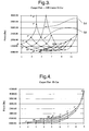
- the graph of Figure 3 shows a data series 52 associated with a distance of 3" into the collapse stroke.
- the graph of Figure 3 also shows an intersecting line 54 associated with an in-car tilt angle of 10°. The point of intersection of the data series 52 and intersection line 54 can be traced back to the Y-axis in parallel to the X-axis to determine the force F s ( ⁇ , x) acting on the first steering column member.
- the force would be approximately 2250 lbs.
- a carpet plot can be used to determine substantially accurate numerical values and also to provide an overall view of the performance and trends of a steering column. For example, the observer can conclude a number of things just by looking at the carpet plot. First, it can be seen that the force on the driver decreases as the angle increases in this environment. Other environments, such as differently configured steering columns, could produce different results. Second, the force first decreases as the steering column strokes at any particular angle. Because these trends are so evident on a carpet plot, it is an efficient way to compare the performance of different steering column designs.
- the graph of Figure 3 shows performance when the impacting force is offset with longitudinal axis of the first steering column member and the graph of Figure 3 shows performance when the impacting force is aligned with longitudinal axis of the first steering column member.
- the differences are due, at least in part, to the impact location being at the bottom of the steering wheel.
- One reason why the forces at higher angles can be less than those found on center is because the moment caused by the location of the load on the steering wheel offsets the cantilever effect.
- the cantilever effect produces large friction forces on interfacing parts that move during collapse. Reducing these forces would cause a corresponding reduction in the overall force on the driver, which is displayed in both the equations and carpet plots displayed previously in this section.
Landscapes
- Engineering & Computer Science (AREA)
- Chemical & Material Sciences (AREA)
- Combustion & Propulsion (AREA)
- Transportation (AREA)
- Mechanical Engineering (AREA)
- Steering Controls (AREA)
Abstract
Description
- The invention relates to an adjustable energy absorbing system for a steering column of a vehicle.
- Steering column assemblies for vehicles often include kinetic energy absorption/dissipation devices that control the collapse of the column in the event of a crash to reduce the likelihood of injury to the driver. One form of an energy absorbing device comprises a metal strap that is bent and drawn over an anvil to absorb kinetic energy of a collapsing column. Examples of this type of energy absorbing device include U.S. Patent Nos. 6,170,874; 6,189,929; 6,322,103; and 6,652,002. The rate of energy dissipation can be adjusted, as shown in U.S. Patent Nos. 6,749,221; 6,652,002; and 6,641,167. The adjustment of the rate of energy absorbed/dissipated can be made in response to speed of the vehicle and the mass of the driver.
- The invention provides a method and apparatus that improves the adjustment of energy absorbing properties of the steering column of a vehicle. The method includes the step of disposing a first steering column member for axial movement along an extension path between an extended position and a retracted position relative to a second steering column member. The first steering column member is also disposed for pivoting movement along a pivot path between a tilt-up position and a tilt-down position relative to the second steering column member. The method includes the step of absorbing energy associated with relative movement between first and second steering column members along the extension path at a first rate with a first device. The first device can be any type of energy absorbing arrangement known in the art, such as an arrangement including a strap and an anvil. The method includes the step of adjusting the first rate of energy absorbed during said absorbing step with a second device. The second device adjusts the first device in response to at least one of a position of the first steering column member along the extension path and a position of the first steering column member along the pivot path. The rate of energy absorption is thus reflective of the extension of the first steering column member or the tilt position of the first steering column member. In one embodiment of the invention, the second device can adjust the first device in response to both of the extension of the first steering column member and the tilt position of the first steering column member.
- The invention improves the adjustment of energy absorbing properties of the steering column of a vehicle. For example, the forces acting on the steering column during collapse are different when the impacting force is centered along the axis of the steering column than when the impacting force is offset with respect to the axis of the steering column. The invention contemplates the differences and adjusts the energy absorbing properties of the steering column accordingly.
- Other advantages of the present invention will be readily appreciated as the same becomes better understood by reference to the following detailed description when considered in connection with the accompanying drawings wherein:
- Figure 1 is a schematic view of an exemplary embodiment of the invention;
- Figure 2 is a second schematic view showing forces acting on a first steering column member of the exemplary embodiment of the invention;
- Figure 3 is a graph showing a carpet plot of the forces acting against collapse of the steering column based on the extension and pivot angle of the first steering column member and also based on off-center impact; and
- Figure 4 is a graph showing a carpet plot of the forces acting against collapse of the steering column based on the extension and pivot angle of the first steering column member and also based on centered impact.
- Referring now to Figure 1, the invention provides a method and apparatus that improves the adjustment of energy absorbing properties of the steering column of a vehicle. The method includes the step of disposing a first
steering column member 12 for axial movement along anextension path 14 between an extendedposition 16 and a retractedposition 18 relative to a secondsteering column member 20. The firststeering column member 12 is also disposed for pivoting movement along apivot path 22 between a tilt-upposition 24 and a tilt-downposition 26 relative to the secondsteering column member 20. The method includes the step of absorbing energy associated with relative movement between first and secondsteering column members extension path 14 at a first rate with afirst device 28. Thefirst device 28 can be any type of energy absorbing arrangement known in the art, such as an arrangement including a strap and an anvil. The method includes the step of adjusting the first rate of energy absorbed during said absorbing step with asecond device 30. The second device adjusts thefirst device 28 in response to at least one of a position of the firststeering column member 12 along theextension path 14 and a position of the firststeering column member 12 along thepivot path 22. The rate of energy absorption is thus reflective of the extension of the firststeering column member 12 or the tilt position of the firststeering column member 12. In one embodiment of the invention, thesecond device 30 can adjust thefirst device 28 in response to both of the extension of the firststeering column member 12 and the tilt position of the firststeering column member 12. - The first
steering column member 12 can be any steering column member moveable axially and pivotally, such as a tilt housing in combination with an upper jacket, a combination of the tilt housing and the upper jacket and a lower jacket, or a combination of upper and lower jackets. The secondsteering column member 20 can be any steering column member such as bracket that is fixedly associated with the vehicle and a lower jacket. - The first and second
steering column members steering column member 12 could be a tilt housing in combination with an upper jacket and the secondsteering column member 20 could be a bracket fixedly associated with the vehicle. The tilt housing would be associated with an upper jacket, being operable to pivot relative to the upper jacket and moveable along theextension path 14 relative to the bracket. In another example, the firststeering column member 12 is the combined tilt housing and upper jacket and lower jacket and the secondsteering column member 20 is a bracket that connects the combined tilt housing and upper jacket and lower jacket to the vehicle. During adjustment, the combined tilt housing and upper jacket and lower jacket may move relative to one another to adjust the position of the steering wheel. At least one of the tilt housing and upper jacket and lower jacket moves relative to the bracket during adjustment. In alternative embodiments of the invention, a lock can be disposed between the first and secondsteering column members extension path 14 with respect to the bracket. The bracket could be releasibly associated with either of the upper and lower jackets, for example, by a capsule. In another example, the firststeering column member 12 could be an upper jacket and the second steering column member could be a lower jacket. The jackets may not pivot relative to one another, but may move along thepivot path 22 in unison. - Figure 1 shows that the
extension path 14 moves with the firststeering column member 12 along thepivot path 22. In alternative embodiments of the invention, theextension path 14 can be fixed with respect to the vehicle and the firststeering column member 12 could be moveable about analternative pivot path 38. - The
extension path 14 includes afirst portion 40 corresponding to a range of available telescopic adjustment controlled by the driver. Thefirst portion 40 includes theextended position 16. Theextension path 14 also includes asecond portion 42 corresponding to telescopic collapse of the firststeering column member 12. Thesecond portion 42 includes the retractedposition 18. Anintermediate position 44 is disposed along theextension path 14 between the extended and retractedpositions intermediate position 44 corresponds to maximum retraction of the firststeering column member 12 over thefirst portion 40. In other words, theintermediate position 44 corresponds to the driver adjusting the firststeering column member 12 to be as retracted as allowable within the range of available telescopic adjustment controlled by the driver. The firststeering column member 12 can move along both first andsecond portions extension path 14. For example, if the firststeering column member 12 is disposed at theintermediate position 44 and a collapsing force is applied to the firststeering column member 12, the firststeering column member 12 can move from theintermediate position 44 towards the retractedposition 18 along theextension path 14. - Energy is absorbed in response to relative movement between first and second
steering column members extension path 14 at a first rate by thefirst device 28. Energy is absorbed as the firststeering column member 12 moves relative to the secondsteering column member 20 along theextension path 14 at least until the firststeering column member 12 reaches the retractedposition 14. In some embodiments of the invention, the firststeering column member 12 can be prevented from moving past the retractedposition 18. The rate of energy absorbed in response to movement can be varied. Thefirst device 28 can be any energy-absorbing steering column system known in the art, including systems having a strap and an anvil. In such systems, adjustment can be accomplished by adjusting the configuration of the strap or of the anvil. Thefirst device 28 can be adjusted using any known method and apparatus of energy absorption including U.S. Patent Nos. 6,749,221; 6,652,002; and 6,641,167, which are hereby incorporated by reference in their entireties. - Referring now additionally to Figure 2, the collapse of the first
steering column member 12 occurs in response to an impacting force F applied the firststeering column member 12. The impacting force F can be coaxial with alongitudinal axis 46 of the column or applied offset with respect to thelongitudinal axis 46 of the firststeering column member 12. When the collapsing force F is applied offset with respect to the longitudinal axis of the column, such as on arim 48 of asteering wheel 50, additional forces can be generated, such as frictional forces. - Figure 2 is a free body diagram helpful in analyzing the steering column system, which includes the first and second
steering column members steering column member 20 is not shown. The second steering column member would be disposed proximate to the position of reaction force R1, discussed in greater detail below. One of the assumptions made in the calculations associated with the free body diagram is that the height of the column in the Y-direction is neglected. This means that all of the forces included in the free body diagram are in contact with thelongitudinal axis 46 of the steering shaft (X-axis), even though the free body diagram displays these forces at different distances away from thisaxis 46. Other assumptions made in this section include: the entire column is a perfect rigid body / no deflection; the column equation is static, not dynamic; and the coefficient of friction between all sliding surfaces is a constant. - The force F is the force generated by the driver during an impact with the steering wheel. F cos θ is the component of F that acts parallel to the a longitudinal, or center, axis of the first steering column member. F sin θ is the component of F that acts transverse to the a longitudinal, or center, axis of the first steering column member.
- In the exemplary embodiment of the invention, the reaction force R1 is disposed at a centerline of a capsule that releasibly associates the first and second steering column with respect to one another. A distance a extends between the centerline of the capsule to a rim of a steering wheel. A distance b-x corresponds to the degree of collapse of the steering column. When x = 0, the first steering column member has not begun to collapse.
- At least one difference between the off-center impact and the analysis where the force is located along the center of the steering shaft is a distance c in the free body diagram. This distance c creates moments and reactions forces R1 and R2. The reaction forces R1 and R2 affect the frictional forces µR1 and µR2 during collapse.
- When x = 0 and forces in the Y-direction and moments are summed about a point proximate to reaction force R2 :


- Using the force and
moment equations 


- To simplify the
equations 

- The forces in the X-direction are considered to determine the equation for the force Fs(x) acting on the driver during a crash event. Absolute values are used on the friction forces because the off-center geometry in certain cases allows for a friction force in the same direction as the driver force F:

- The reaction forces R1 and R2 can be replaced in equation 9 with equations 7 and 8:

- To simplify
equation 10, the common term present in both absolute values will be defined as Z:
- Therefore, the force Fs(x) on the driver can be solved by the following equation:


- After analyzing the equations, it can be determined that the off-center impact reveals many characteristics that are different with respect to a center impact. One difference is that the final equation 13 has a different format than center impacts. The absolute values that are necessary in the off-center impact restrict the equation from being simplified to the degree of center impact equations. This means that the denominator of the final equation is more complex because there are multiple sin and cos terms. Another difference is that the strap force located in the numerator is negative, rather than positive.
- Referring now additionally to Figures 3 and 4, another tool to help demonstrate the difference between the usual centerline impact and the off-center impact is a carpet plots of the equations associated with center and off-center impacts.
- Carpet plots do not use the traditional X and Y axis format. The X-axis is not used when reading a carpet plot. The data series that arise from the X-axis are the force vs. angle series for different stroke lengths. These data series' are generally convex with respect to the Y-axis in the exemplary graph. The intersecting lines with the preceding data series are force vs. stroke length series for multiple column in-car angles. These intersecting lines are generally concave with respect to the Y-axis in the exemplary graph.
- In one example, assume it is desired to find the force Fs(θ, x) acting on the driver during collapse when the first
steering column member 12 is at a position along thepivot path 22 corresponding to an in-car tilt angle of 10° and at a position along theextension path 14 corresponding to 3" into the collapse stroke. The graph of Figure 3 shows adata series 52 associated with a distance of 3" into the collapse stroke. The graph of Figure 3 also shows an intersectingline 54 associated with an in-car tilt angle of 10°. The point of intersection of thedata series 52 andintersection line 54 can be traced back to the Y-axis in parallel to the X-axis to determine the force Fs(θ, x) acting on the first steering column member. In this example, the force would be approximately 2250 lbs. - A carpet plot can be used to determine substantially accurate numerical values and also to provide an overall view of the performance and trends of a steering column. For example, the observer can conclude a number of things just by looking at the carpet plot. First, it can be seen that the force on the driver decreases as the angle increases in this environment. Other environments, such as differently configured steering columns, could produce different results. Second, the force first decreases as the steering column strokes at any particular angle. Because these trends are so evident on a carpet plot, it is an efficient way to compare the performance of different steering column designs.
- Referring now additionally to Figure 4, the two carpet plots displayed look considerably different despite the fact that they use the same dimensions. The graph of Figure 3 shows performance when the impacting force is offset with longitudinal axis of the first steering column member and the graph of Figure 3 shows performance when the impacting force is aligned with longitudinal axis of the first steering column member. The differences are due, at least in part, to the impact location being at the bottom of the steering wheel. One reason why the forces at higher angles can be less than those found on center is because the moment caused by the location of the load on the steering wheel offsets the cantilever effect. The cantilever effect produces large friction forces on interfacing parts that move during collapse. Reducing these forces would cause a corresponding reduction in the overall force on the driver, which is displayed in both the equations and carpet plots displayed previously in this section.
- While the invention has been described with reference to an exemplary embodiment, it will be understood by those skilled in the art that various changes may be made and equivalents may be substituted for elements thereof without departing from the scope of the invention. In addition, many modifications may be made to adapt a particular situation or material to the teachings of the invention without departing from the essential scope thereof. Therefore, it is intended that the invention not be limited to the particular embodiment disclosed as the best mode contemplated for carrying out this invention, but that the invention will include all embodiments falling within the scope of the appended claims.
Claims (11)
- An apparatus (10) comprising:first and second steering column members (12, 20), wherein said first steering column member (12) being disposed for axial movement along an extension path (14) between an extended position (16) and a retracted position (18) relative to said second steering column member (20) and for pivoting movement along a pivot path (22) between a tilt-up position (24) and a tilt-down position (26);a first device (28) operable to absorb energy associated with relative movement between said first and second steering column members (12, 20) along said extension path (14) at a first rate; anda second device (30) operable to adjust said first rate of energy absorbed by the first device (28) in response to at least one of a position of said first steering column member (12) along said extension path (14) and a position of said first steering column member (12) along said pivot path (22).
- The apparatus (10) of claim 1 wherein said second device (30) includes at least one sensor (32, 34) operable to sense at least one of said position of said first steering column member (12) along said extension path (14) and said position of said first steering column member (12) along said pivot path (22).
- The apparatus (10) of claim 2 wherein said second device (30) includes a controller (30) communicating with said at least one sensor (32, 34).
- A method comprising the steps of:disposing a first steering column member (12) for axial movement along an extension path (14) between an extended position (16) and a retracted position (18) relative to a second steering column member (20) and for pivoting movement along a pivot path (22) between a tilt-up position (24) and a tilt-down position (26);absorbing energy associated with relative movement between first and second steering column members (12, 20) along the extension path (14) at a first rate with a first device (28); andadjusting the first rate of energy absorbed during said absorbing step in response to at least one of a position of the first steering column member (12) along the extension path (14) and a position of the first steering column member (12) along the pivot path (22) with a second device (30).
- The method of claim 4 including the step of:sensing at least one of the position of the first steering column member (12) along the extension path (14) and the position of the first steering column member (12) along the pivot path (22).
- The method of claim 5 including the step of:controlling the adjustment of the first rate of energy absorbed during said adjusting step in response to the at least one position sensed during said sensing step with a controller (30).
- The method of claim 6 wherein said adjusting step if further defined as adjusting the first rate of energy absorbed during said absorbing step in response to both of the position of the first steering column member (12) along the extension path (14) and the position of the first steering column member (12) along the pivot path (22).
- The method of claim 7 wherein said sensing step if further defined as sensing both the position of the first steering column member (12) along the extension path (14) and the position of the first steering column member (12) along the pivot path (22).
- The method of claim 8 wherein said controlling step if further defined as controlling the adjustment of the first rate of energy absorbed during said adjusting step in response to both of the positions sensed during said sensing step with the controller (30).
- The method of claim 9 wherein said adjusting step is further defined as increasing the first rate of energy absorbed.
- The method of claim 9 wherein said adjusting step is further defined as decreasing the first rate of energy absorbed.
Applications Claiming Priority (1)
| Application Number | Priority Date | Filing Date | Title |
|---|---|---|---|
| US10/932,833 US7334817B2 (en) | 2004-09-02 | 2004-09-02 | Active energy absorption method using tilt and telescope positions |
Publications (3)
| Publication Number | Publication Date |
|---|---|
| EP1632418A2 true EP1632418A2 (en) | 2006-03-08 |
| EP1632418A3 EP1632418A3 (en) | 2007-08-22 |
| EP1632418B1 EP1632418B1 (en) | 2012-10-10 |
Family
ID=35056852
Family Applications (1)
| Application Number | Title | Priority Date | Filing Date |
|---|---|---|---|
| EP05076978A Expired - Lifetime EP1632418B1 (en) | 2004-09-02 | 2005-08-30 | Controlled energy absorption for a steering column depending on its tilt and telescope positions |
Country Status (2)
| Country | Link |
|---|---|
| US (1) | US7334817B2 (en) |
| EP (1) | EP1632418B1 (en) |
Cited By (2)
| Publication number | Priority date | Publication date | Assignee | Title |
|---|---|---|---|---|
| DE102010020088A1 (en) | 2010-05-10 | 2011-11-10 | Thyssenkrupp Presta Ag | Control of a controllable energy absorber |
| WO2020025466A1 (en) * | 2018-07-31 | 2020-02-06 | Thyssenkrupp Presta Ag | Position detection for a steering column of a motor vehicle |
Citations (6)
| Publication number | Priority date | Publication date | Assignee | Title |
|---|---|---|---|---|
| US6170874B1 (en) | 1996-11-21 | 2001-01-09 | Ab Volvo | Variable energy-absorbing steering column |
| US6189929B1 (en) | 1999-11-02 | 2001-02-20 | Trw Inc. | Adaptive collapsible steering column |
| US6322103B1 (en) | 1999-06-11 | 2001-11-27 | Delphi Technologies, Inc. | Energy absorber for motor vehicle steering column |
| US6641167B2 (en) | 2001-10-16 | 2003-11-04 | Delphi Technologies, Inc. | Responsive E/A system for steering columns |
| US6652002B2 (en) | 2001-10-19 | 2003-11-25 | Delphi Technologies, Inc. | Crash responsive energy absorbing device for a steering column |
| US6749221B2 (en) | 2002-06-28 | 2004-06-15 | Delphi Technologies, Inc. | Active steering column energy absorbing device |
Family Cites Families (28)
| Publication number | Priority date | Publication date | Assignee | Title |
|---|---|---|---|---|
| US4886296A (en) * | 1987-09-25 | 1989-12-12 | Volkswagen Ag | Belt force limiting device |
| US4850239A (en) * | 1988-01-29 | 1989-07-25 | General Motors Corporation | Steering wheel hub and upper steering shaft assembly for tilt head steering columns |
| US4886295A (en) | 1988-12-05 | 1989-12-12 | General Motors Corporation | Vehicle occupant protection system |
| CA2011938C (en) * | 1989-04-07 | 1997-02-11 | Warren K. Adams | Testing method and apparatus |
| US4970910A (en) * | 1989-11-13 | 1990-11-20 | General Motors Corporation | Steering column with tilt-adjustable steering wheel |
| GB9010304D0 (en) | 1990-05-08 | 1990-06-27 | Torrington Co | Mechanism for absorbing energy transmitted through a vehicle steering column |
| DE4030405C2 (en) | 1990-09-26 | 1994-01-27 | Porsche Ag | Adjustable safety steering column for a motor vehicle |
| GB2281539A (en) * | 1993-09-01 | 1995-03-08 | Torrington Co | Adjustable vehicle steering column assembly |
| FR2713188B1 (en) * | 1993-11-29 | 1996-02-23 | Nacam | Energy absorption device for a motor vehicle steering column. |
| FR2714648B1 (en) * | 1994-01-06 | 1996-03-15 | Nacam | Axially-held energy absorption device for a motor vehicle steering column. |
| FR2714651B1 (en) * | 1994-01-06 | 1996-03-15 | Nacam | Energy absorption device for a motor vehicle steering column. |
| US5692778A (en) * | 1996-11-14 | 1997-12-02 | General Motors Corporation | Motor vehicle steering column |
| US5802926A (en) * | 1997-03-21 | 1998-09-08 | Chrysler Corporation | Collapsible steering column assembly |
| US5899116A (en) * | 1997-12-08 | 1999-05-04 | General Motors Corporation | Connection for energy-absorbing steering column |
| DE19812179C1 (en) * | 1998-03-19 | 1999-08-19 | Daimler Chrysler Ag | Vehicle steering column assembly to absorb impact energy on a collision |
| JP3591284B2 (en) * | 1998-03-20 | 2004-11-17 | 日本精工株式会社 | Swing support device for steering column for tilt type steering device |
| US6152488A (en) | 1999-06-16 | 2000-11-28 | Ford Global Technologies, Inc. | Steering column with variable collapse force |
| JP2001058552A (en) * | 1999-08-04 | 2001-03-06 | Takata Corp | Damage reduction system vehicle crash |
| US6394241B1 (en) * | 1999-10-21 | 2002-05-28 | Simula, Inc. | Energy absorbing shear strip bender |
| US6726248B2 (en) * | 2000-05-16 | 2004-04-27 | Nsk Ltd. | Impact absorbing type steering column apparatus |
| JP4470299B2 (en) * | 2000-08-29 | 2010-06-02 | 日本精工株式会社 | Shock absorbing steering column device |
| US6769715B2 (en) * | 2001-10-19 | 2004-08-03 | Richard Kremer Riefe | Responsive energy absorbing device for a steering column |
| CN100369779C (en) * | 2002-07-08 | 2008-02-20 | 日本精工株式会社 | Electric Steering |
| JP4124021B2 (en) | 2002-10-07 | 2008-07-23 | トヨタ自動車株式会社 | Shock absorbing steering column device |
| US6916044B2 (en) * | 2003-07-08 | 2005-07-12 | Daimlerchrysler Corporation | Steering column/airbag tunable impact absorption system |
| JP2006044641A (en) * | 2004-06-28 | 2006-02-16 | Aisin Seiki Co Ltd | Shock absorbing steering device |
| US7325834B2 (en) * | 2004-08-10 | 2008-02-05 | Delphi Technologies, Inc. | Adaptive strap energy absorber with pin puller |
| KR100553962B1 (en) * | 2004-09-07 | 2006-02-21 | 현대모비스 주식회사 | Steering Column with Variable Shock Absorption Structure |
-
2004
- 2004-09-02 US US10/932,833 patent/US7334817B2/en not_active Expired - Lifetime
-
2005
- 2005-08-30 EP EP05076978A patent/EP1632418B1/en not_active Expired - Lifetime
Patent Citations (6)
| Publication number | Priority date | Publication date | Assignee | Title |
|---|---|---|---|---|
| US6170874B1 (en) | 1996-11-21 | 2001-01-09 | Ab Volvo | Variable energy-absorbing steering column |
| US6322103B1 (en) | 1999-06-11 | 2001-11-27 | Delphi Technologies, Inc. | Energy absorber for motor vehicle steering column |
| US6189929B1 (en) | 1999-11-02 | 2001-02-20 | Trw Inc. | Adaptive collapsible steering column |
| US6641167B2 (en) | 2001-10-16 | 2003-11-04 | Delphi Technologies, Inc. | Responsive E/A system for steering columns |
| US6652002B2 (en) | 2001-10-19 | 2003-11-25 | Delphi Technologies, Inc. | Crash responsive energy absorbing device for a steering column |
| US6749221B2 (en) | 2002-06-28 | 2004-06-15 | Delphi Technologies, Inc. | Active steering column energy absorbing device |
Cited By (5)
| Publication number | Priority date | Publication date | Assignee | Title |
|---|---|---|---|---|
| DE102010020088A1 (en) | 2010-05-10 | 2011-11-10 | Thyssenkrupp Presta Ag | Control of a controllable energy absorber |
| WO2011141098A1 (en) | 2010-05-10 | 2011-11-17 | Thyssenkrupp Presta Ag | Method and device for controlling a controllable energy absorber |
| DE102010020088B4 (en) * | 2010-05-10 | 2013-06-27 | Thyssenkrupp Presta Aktiengesellschaft | Method and device for controlling a controllable energy absorber |
| WO2020025466A1 (en) * | 2018-07-31 | 2020-02-06 | Thyssenkrupp Presta Ag | Position detection for a steering column of a motor vehicle |
| US12139188B2 (en) | 2018-07-31 | 2024-11-12 | Thyssenkrupp Presta Ag | Position detection for a steering column of a motor vehicle |
Also Published As
| Publication number | Publication date |
|---|---|
| EP1632418B1 (en) | 2012-10-10 |
| US7334817B2 (en) | 2008-02-26 |
| EP1632418A3 (en) | 2007-08-22 |
| US20060043721A1 (en) | 2006-03-02 |
Similar Documents
| Publication | Publication Date | Title |
|---|---|---|
| US6454302B1 (en) | Energy absorber for motor vehicle steering column | |
| US20070228716A1 (en) | Collapsible steering column assembly and method of operation | |
| US6213510B1 (en) | Occupant restraint apparatus and method of controlling occupant restraint apparatus | |
| US7731235B2 (en) | Steering column for a motor vehicle | |
| US6769715B2 (en) | Responsive energy absorbing device for a steering column | |
| US8123251B2 (en) | Collapsible steering column assembly | |
| US4452096A (en) | Energy absorbing steering column and capsule mounting therefore | |
| EP1520768B1 (en) | Vehicle shock absorption type steering column device | |
| EP1439993B1 (en) | Crash responsive energy absorbing device for a steering column | |
| US5052715A (en) | Passive impact restraining vehicular steering column assembly | |
| EP1625063B1 (en) | Energy absorber for motor vehicle steering column | |
| US7490855B2 (en) | Shock-absorption steering device | |
| EP1591342A1 (en) | Horizontally collapsing steering column | |
| US20060033321A1 (en) | Adaptive strap energy absorber with pin puller | |
| US7118131B2 (en) | Adaptive energy absorber | |
| US20040090057A1 (en) | Collapsing steering column with locking tilt mechanism | |
| EP1632418B1 (en) | Controlled energy absorption for a steering column depending on its tilt and telescope positions | |
| JP2005280655A (en) | Shock absorbing steering device | |
| EP1671870A1 (en) | Sterring column collapse guidance system | |
| US20050248141A1 (en) | Adaptive energy absorbing system using pin pullers | |
| US7077433B2 (en) | Three stage rotary strap extruder | |
| US20050247533A1 (en) | Adaptive energy absorber | |
| JP2599596Y2 (en) | Shock absorbing steering system with tilt mechanism | |
| JPH078157U (en) | Steering wheel position adjustment device | |
| JPH02193766A (en) | Steering tilt device control lever |
Legal Events
| Date | Code | Title | Description |
|---|---|---|---|
| PUAI | Public reference made under article 153(3) epc to a published international application that has entered the european phase |
Free format text: ORIGINAL CODE: 0009012 |
|
| AK | Designated contracting states |
Kind code of ref document: A2 Designated state(s): AT BE BG CH CY CZ DE DK EE ES FI FR GB GR HU IE IS IT LI LT LU LV MC NL PL PT RO SE SI SK TR |
|
| AX | Request for extension of the european patent |
Extension state: AL BA HR MK YU |
|
| PUAL | Search report despatched |
Free format text: ORIGINAL CODE: 0009013 |
|
| AK | Designated contracting states |
Kind code of ref document: A3 Designated state(s): AT BE BG CH CY CZ DE DK EE ES FI FR GB GR HU IE IS IT LI LT LU LV MC NL PL PT RO SE SI SK TR |
|
| AX | Request for extension of the european patent |
Extension state: AL BA HR MK YU |
|
| RIC1 | Information provided on ipc code assigned before grant |
Ipc: B62D 1/187 20060101ALI20070713BHEP Ipc: B62D 1/19 20060101AFI20051014BHEP |
|
| 17P | Request for examination filed |
Effective date: 20080222 |
|
| 17Q | First examination report despatched |
Effective date: 20080402 |
|
| AKX | Designation fees paid |
Designated state(s): AT BE BG CH CY CZ DE DK EE ES FI FR GB GR HU IE IS IT LI LT LU LV MC NL PL PT RO SE SI SK TR |
|
| RAP1 | Party data changed (applicant data changed or rights of an application transferred) |
Owner name: GM GLOBAL TECHNOLOGY OPERATIONS, INC. |
|
| RAP1 | Party data changed (applicant data changed or rights of an application transferred) |
Owner name: GM GLOBAL TECHNOLOGY OPERATIONS LLC |
|
| GRAP | Despatch of communication of intention to grant a patent |
Free format text: ORIGINAL CODE: EPIDOSNIGR1 |
|
| GRAS | Grant fee paid |
Free format text: ORIGINAL CODE: EPIDOSNIGR3 |
|
| GRAA | (expected) grant |
Free format text: ORIGINAL CODE: 0009210 |
|
| AK | Designated contracting states |
Kind code of ref document: B1 Designated state(s): AT BE BG CH CY CZ DE DK EE ES FI FR GB GR HU IE IS IT LI LT LU LV MC NL PL PT RO SE SI SK TR |
|
| REG | Reference to a national code |
Ref country code: GB Ref legal event code: FG4D |
|
| REG | Reference to a national code |
Ref country code: AT Ref legal event code: REF Ref document number: 578821 Country of ref document: AT Kind code of ref document: T Effective date: 20121015 Ref country code: CH Ref legal event code: EP |
|
| REG | Reference to a national code |
Ref country code: IE Ref legal event code: FG4D |
|
| REG | Reference to a national code |
Ref country code: DE Ref legal event code: R096 Ref document number: 602005036460 Country of ref document: DE Effective date: 20121213 |
|
| RAP2 | Party data changed (patent owner data changed or rights of a patent transferred) |
Owner name: GM GLOBAL TECHNOLOGY OPERATIONS LLC Owner name: STEERING SOLUTIONS IP HOLDING CORPORATION |
|
| PG25 | Lapsed in a contracting state [announced via postgrant information from national office to epo] |
Ref country code: SI Free format text: LAPSE BECAUSE OF FAILURE TO SUBMIT A TRANSLATION OF THE DESCRIPTION OR TO PAY THE FEE WITHIN THE PRESCRIBED TIME-LIMIT Effective date: 20121010 |
|
| REG | Reference to a national code |
Ref country code: NL Ref legal event code: VDEP Effective date: 20121010 Ref country code: DE Ref legal event code: R082 Ref document number: 602005036460 Country of ref document: DE Representative=s name: MANITZ, FINSTERWALD & PARTNER GBR, DE |
|
| REG | Reference to a national code |
Ref country code: AT Ref legal event code: MK05 Ref document number: 578821 Country of ref document: AT Kind code of ref document: T Effective date: 20121010 |
|
| REG | Reference to a national code |
Ref country code: LT Ref legal event code: MG4D |
|
| PG25 | Lapsed in a contracting state [announced via postgrant information from national office to epo] |
Ref country code: IS Free format text: LAPSE BECAUSE OF FAILURE TO SUBMIT A TRANSLATION OF THE DESCRIPTION OR TO PAY THE FEE WITHIN THE PRESCRIBED TIME-LIMIT Effective date: 20130210 Ref country code: LT Free format text: LAPSE BECAUSE OF FAILURE TO SUBMIT A TRANSLATION OF THE DESCRIPTION OR TO PAY THE FEE WITHIN THE PRESCRIBED TIME-LIMIT Effective date: 20121010 Ref country code: ES Free format text: LAPSE BECAUSE OF FAILURE TO SUBMIT A TRANSLATION OF THE DESCRIPTION OR TO PAY THE FEE WITHIN THE PRESCRIBED TIME-LIMIT Effective date: 20130121 Ref country code: NL Free format text: LAPSE BECAUSE OF FAILURE TO SUBMIT A TRANSLATION OF THE DESCRIPTION OR TO PAY THE FEE WITHIN THE PRESCRIBED TIME-LIMIT Effective date: 20121010 Ref country code: FI Free format text: LAPSE BECAUSE OF FAILURE TO SUBMIT A TRANSLATION OF THE DESCRIPTION OR TO PAY THE FEE WITHIN THE PRESCRIBED TIME-LIMIT Effective date: 20121010 Ref country code: SE Free format text: LAPSE BECAUSE OF FAILURE TO SUBMIT A TRANSLATION OF THE DESCRIPTION OR TO PAY THE FEE WITHIN THE PRESCRIBED TIME-LIMIT Effective date: 20121010 |
|
| REG | Reference to a national code |
Ref country code: DE Ref legal event code: R081 Ref document number: 602005036460 Country of ref document: DE Owner name: GM GLOBAL TECHNOLOGY OPERATIONS LLC (N. D. GES, US Free format text: FORMER OWNER: GM GLOBAL TECHNOLOGY OPERATIONS, LLC, DETROIT, MICH., US Effective date: 20130313 Ref country code: DE Ref legal event code: R081 Ref document number: 602005036460 Country of ref document: DE Owner name: STEERING SOLUTIONS IP HOLDING CORP., SAGINAW, US Free format text: FORMER OWNER: DELPHI TECHNOLOGIES, INC., TROY, MICH., US Effective date: 20121010 Ref country code: DE Ref legal event code: R081 Ref document number: 602005036460 Country of ref document: DE Owner name: GM GLOBAL TECHNOLOGY OPERATIONS LLC (N. D. GES, US Free format text: FORMER OWNER: DELPHI TECHNOLOGIES, INC., TROY, MICH., US Effective date: 20121010 Ref country code: DE Ref legal event code: R081 Ref document number: 602005036460 Country of ref document: DE Owner name: STEERING SOLUTIONS IP HOLDING CORP., SAGINAW, US Free format text: FORMER OWNER: GM GLOBAL TECHNOLOGY OPERATIONS, LLC, DETROIT, MICH., US Effective date: 20130313 Ref country code: DE Ref legal event code: R081 Ref document number: 602005036460 Country of ref document: DE Owner name: GM GLOBAL TECHNOLOGY OPERATIONS LLC (N. D. GES, US Free format text: FORMER OWNER: DELPHI TECHNOLOGIES, INC., TROY, US Effective date: 20121010 Ref country code: DE Ref legal event code: R081 Ref document number: 602005036460 Country of ref document: DE Owner name: GM GLOBAL TECHNOLOGY OPERATIONS LLC (N. D. GES, US Free format text: FORMER OWNER: GM GLOBAL TECHNOLOGY OPERATIONS, LLC, DETROIT, US Effective date: 20130313 Ref country code: DE Ref legal event code: R081 Ref document number: 602005036460 Country of ref document: DE Owner name: STEERING SOLUTIONS IP HOLDING CORP., US Free format text: FORMER OWNER: GM GLOBAL TECHNOLOGY OPERATIONS, LLC, DETROIT, US Effective date: 20130313 Ref country code: DE Ref legal event code: R082 Ref document number: 602005036460 Country of ref document: DE Representative=s name: MANITZ, FINSTERWALD & PARTNER GBR, DE Effective date: 20130313 Ref country code: DE Ref legal event code: R081 Ref document number: 602005036460 Country of ref document: DE Owner name: STEERING SOLUTIONS IP HOLDING CORP., US Free format text: FORMER OWNER: DELPHI TECHNOLOGIES, INC., TROY, US Effective date: 20121010 Ref country code: DE Ref legal event code: R082 Ref document number: 602005036460 Country of ref document: DE Representative=s name: MANITZ FINSTERWALD PATENTANWAELTE PARTMBB, DE Effective date: 20130313 |
|
| PG25 | Lapsed in a contracting state [announced via postgrant information from national office to epo] |
Ref country code: GR Free format text: LAPSE BECAUSE OF FAILURE TO SUBMIT A TRANSLATION OF THE DESCRIPTION OR TO PAY THE FEE WITHIN THE PRESCRIBED TIME-LIMIT Effective date: 20130111 Ref country code: PL Free format text: LAPSE BECAUSE OF FAILURE TO SUBMIT A TRANSLATION OF THE DESCRIPTION OR TO PAY THE FEE WITHIN THE PRESCRIBED TIME-LIMIT Effective date: 20121010 Ref country code: CY Free format text: LAPSE BECAUSE OF FAILURE TO SUBMIT A TRANSLATION OF THE DESCRIPTION OR TO PAY THE FEE WITHIN THE PRESCRIBED TIME-LIMIT Effective date: 20121010 Ref country code: LV Free format text: LAPSE BECAUSE OF FAILURE TO SUBMIT A TRANSLATION OF THE DESCRIPTION OR TO PAY THE FEE WITHIN THE PRESCRIBED TIME-LIMIT Effective date: 20121010 Ref country code: PT Free format text: LAPSE BECAUSE OF FAILURE TO SUBMIT A TRANSLATION OF THE DESCRIPTION OR TO PAY THE FEE WITHIN THE PRESCRIBED TIME-LIMIT Effective date: 20130211 Ref country code: BE Free format text: LAPSE BECAUSE OF FAILURE TO SUBMIT A TRANSLATION OF THE DESCRIPTION OR TO PAY THE FEE WITHIN THE PRESCRIBED TIME-LIMIT Effective date: 20121010 |
|
| PG25 | Lapsed in a contracting state [announced via postgrant information from national office to epo] |
Ref country code: AT Free format text: LAPSE BECAUSE OF FAILURE TO SUBMIT A TRANSLATION OF THE DESCRIPTION OR TO PAY THE FEE WITHIN THE PRESCRIBED TIME-LIMIT Effective date: 20121010 |
|
| PG25 | Lapsed in a contracting state [announced via postgrant information from national office to epo] |
Ref country code: CZ Free format text: LAPSE BECAUSE OF FAILURE TO SUBMIT A TRANSLATION OF THE DESCRIPTION OR TO PAY THE FEE WITHIN THE PRESCRIBED TIME-LIMIT Effective date: 20121010 Ref country code: DK Free format text: LAPSE BECAUSE OF FAILURE TO SUBMIT A TRANSLATION OF THE DESCRIPTION OR TO PAY THE FEE WITHIN THE PRESCRIBED TIME-LIMIT Effective date: 20121010 Ref country code: SK Free format text: LAPSE BECAUSE OF FAILURE TO SUBMIT A TRANSLATION OF THE DESCRIPTION OR TO PAY THE FEE WITHIN THE PRESCRIBED TIME-LIMIT Effective date: 20121010 Ref country code: EE Free format text: LAPSE BECAUSE OF FAILURE TO SUBMIT A TRANSLATION OF THE DESCRIPTION OR TO PAY THE FEE WITHIN THE PRESCRIBED TIME-LIMIT Effective date: 20121010 Ref country code: BG Free format text: LAPSE BECAUSE OF FAILURE TO SUBMIT A TRANSLATION OF THE DESCRIPTION OR TO PAY THE FEE WITHIN THE PRESCRIBED TIME-LIMIT Effective date: 20130110 |
|
| PLBE | No opposition filed within time limit |
Free format text: ORIGINAL CODE: 0009261 |
|
| STAA | Information on the status of an ep patent application or granted ep patent |
Free format text: STATUS: NO OPPOSITION FILED WITHIN TIME LIMIT |
|
| PG25 | Lapsed in a contracting state [announced via postgrant information from national office to epo] |
Ref country code: RO Free format text: LAPSE BECAUSE OF FAILURE TO SUBMIT A TRANSLATION OF THE DESCRIPTION OR TO PAY THE FEE WITHIN THE PRESCRIBED TIME-LIMIT Effective date: 20121010 Ref country code: IT Free format text: LAPSE BECAUSE OF FAILURE TO SUBMIT A TRANSLATION OF THE DESCRIPTION OR TO PAY THE FEE WITHIN THE PRESCRIBED TIME-LIMIT Effective date: 20121010 |
|
| 26N | No opposition filed |
Effective date: 20130711 |
|
| REG | Reference to a national code |
Ref country code: DE Ref legal event code: R097 Ref document number: 602005036460 Country of ref document: DE Effective date: 20130711 |
|
| REG | Reference to a national code |
Ref country code: CH Ref legal event code: PL |
|
| GBPC | Gb: european patent ceased through non-payment of renewal fee |
Effective date: 20130830 |
|
| PG25 | Lapsed in a contracting state [announced via postgrant information from national office to epo] |
Ref country code: LI Free format text: LAPSE BECAUSE OF NON-PAYMENT OF DUE FEES Effective date: 20130831 Ref country code: CH Free format text: LAPSE BECAUSE OF NON-PAYMENT OF DUE FEES Effective date: 20130831 Ref country code: MC Free format text: LAPSE BECAUSE OF FAILURE TO SUBMIT A TRANSLATION OF THE DESCRIPTION OR TO PAY THE FEE WITHIN THE PRESCRIBED TIME-LIMIT Effective date: 20121010 Ref country code: DE Free format text: LAPSE BECAUSE OF NON-PAYMENT OF DUE FEES Effective date: 20140301 |
|
| REG | Reference to a national code |
Ref country code: IE Ref legal event code: MM4A |
|
| REG | Reference to a national code |
Ref country code: DE Ref legal event code: R119 Ref document number: 602005036460 Country of ref document: DE Effective date: 20140301 |
|
| REG | Reference to a national code |
Ref country code: FR Ref legal event code: ST Effective date: 20140430 |
|
| PG25 | Lapsed in a contracting state [announced via postgrant information from national office to epo] |
Ref country code: IE Free format text: LAPSE BECAUSE OF NON-PAYMENT OF DUE FEES Effective date: 20130830 Ref country code: GB Free format text: LAPSE BECAUSE OF NON-PAYMENT OF DUE FEES Effective date: 20130830 |
|
| PG25 | Lapsed in a contracting state [announced via postgrant information from national office to epo] |
Ref country code: FR Free format text: LAPSE BECAUSE OF NON-PAYMENT OF DUE FEES Effective date: 20130902 |
|
| PG25 | Lapsed in a contracting state [announced via postgrant information from national office to epo] |
Ref country code: TR Free format text: LAPSE BECAUSE OF FAILURE TO SUBMIT A TRANSLATION OF THE DESCRIPTION OR TO PAY THE FEE WITHIN THE PRESCRIBED TIME-LIMIT Effective date: 20121010 |
|
| PG25 | Lapsed in a contracting state [announced via postgrant information from national office to epo] |
Ref country code: LU Free format text: LAPSE BECAUSE OF NON-PAYMENT OF DUE FEES Effective date: 20130830 Ref country code: HU Free format text: LAPSE BECAUSE OF FAILURE TO SUBMIT A TRANSLATION OF THE DESCRIPTION OR TO PAY THE FEE WITHIN THE PRESCRIBED TIME-LIMIT; INVALID AB INITIO Effective date: 20050830 |