EP1632285A1 - Hydrogen storage material and method for producing same - Google Patents
Hydrogen storage material and method for producing same Download PDFInfo
- Publication number
- EP1632285A1 EP1632285A1 EP04704364A EP04704364A EP1632285A1 EP 1632285 A1 EP1632285 A1 EP 1632285A1 EP 04704364 A EP04704364 A EP 04704364A EP 04704364 A EP04704364 A EP 04704364A EP 1632285 A1 EP1632285 A1 EP 1632285A1
- Authority
- EP
- European Patent Office
- Prior art keywords
- hydrogen
- hydrogen storage
- region
- metal element
- storage material
- Prior art date
- Legal status (The legal status is an assumption and is not a legal conclusion. Google has not performed a legal analysis and makes no representation as to the accuracy of the status listed.)
- Withdrawn
Links
Images

Classifications
-
- C—CHEMISTRY; METALLURGY
- C01—INORGANIC CHEMISTRY
- C01B—NON-METALLIC ELEMENTS; COMPOUNDS THEREOF; METALLOIDS OR COMPOUNDS THEREOF NOT COVERED BY SUBCLASS C01C
- C01B3/00—Hydrogen; Gaseous mixtures containing hydrogen; Separation of hydrogen from mixtures containing it; Purification of hydrogen; Reversible storage of hydrogen
- C01B3/0005—Reversible storage of hydrogen, e.g. by hydrogen getters or electrodes
- C01B3/001—Reversible storage of hydrogen, e.g. by hydrogen getters or electrodes characterised by the uptaking media; Treatment thereof
-
- B—PERFORMING OPERATIONS; TRANSPORTING
- B01—PHYSICAL OR CHEMICAL PROCESSES OR APPARATUS IN GENERAL
- B01J—CHEMICAL OR PHYSICAL PROCESSES, e.g. CATALYSIS OR COLLOID CHEMISTRY; THEIR RELEVANT APPARATUS
- B01J20/00—Solid sorbent compositions or filter aid compositions; Sorbents for chromatography; Processes for preparing, regenerating or reactivating thereof
- B01J20/02—Solid sorbent compositions or filter aid compositions; Sorbents for chromatography; Processes for preparing, regenerating or reactivating thereof comprising inorganic material
- B01J20/20—Solid sorbent compositions or filter aid compositions; Sorbents for chromatography; Processes for preparing, regenerating or reactivating thereof comprising inorganic material comprising free carbon; comprising carbon obtained by carbonising processes
-
- C—CHEMISTRY; METALLURGY
- C01—INORGANIC CHEMISTRY
- C01B—NON-METALLIC ELEMENTS; COMPOUNDS THEREOF; METALLOIDS OR COMPOUNDS THEREOF NOT COVERED BY SUBCLASS C01C
- C01B3/00—Hydrogen; Gaseous mixtures containing hydrogen; Separation of hydrogen from mixtures containing it; Purification of hydrogen; Reversible storage of hydrogen
- C01B3/0005—Reversible storage of hydrogen, e.g. by hydrogen getters or electrodes
- C01B3/001—Reversible storage of hydrogen, e.g. by hydrogen getters or electrodes characterised by the uptaking media; Treatment thereof
- C01B3/0018—Inorganic elements or compounds, e.g. oxides, nitrides, borohydrides or zeolites; Solutions thereof
- C01B3/0021—Elemental carbon, e.g. active carbon, carbon nanotubes or fullerenes
-
- C—CHEMISTRY; METALLURGY
- C01—INORGANIC CHEMISTRY
- C01B—NON-METALLIC ELEMENTS; COMPOUNDS THEREOF; METALLOIDS OR COMPOUNDS THEREOF NOT COVERED BY SUBCLASS C01C
- C01B3/00—Hydrogen; Gaseous mixtures containing hydrogen; Separation of hydrogen from mixtures containing it; Purification of hydrogen; Reversible storage of hydrogen
- C01B3/0005—Reversible storage of hydrogen, e.g. by hydrogen getters or electrodes
- C01B3/001—Reversible storage of hydrogen, e.g. by hydrogen getters or electrodes characterised by the uptaking media; Treatment thereof
- C01B3/0018—Inorganic elements or compounds, e.g. oxides, nitrides, borohydrides or zeolites; Solutions thereof
- C01B3/0026—Metals or metal hydrides
-
- C—CHEMISTRY; METALLURGY
- C01—INORGANIC CHEMISTRY
- C01B—NON-METALLIC ELEMENTS; COMPOUNDS THEREOF; METALLOIDS OR COMPOUNDS THEREOF NOT COVERED BY SUBCLASS C01C
- C01B3/00—Hydrogen; Gaseous mixtures containing hydrogen; Separation of hydrogen from mixtures containing it; Purification of hydrogen; Reversible storage of hydrogen
- C01B3/0005—Reversible storage of hydrogen, e.g. by hydrogen getters or electrodes
- C01B3/001—Reversible storage of hydrogen, e.g. by hydrogen getters or electrodes characterised by the uptaking media; Treatment thereof
- C01B3/0078—Composite solid storage media, e.g. mixtures of polymers and metal hydrides, coated solid compounds or structurally heterogeneous solid compounds
-
- C—CHEMISTRY; METALLURGY
- C01—INORGANIC CHEMISTRY
- C01B—NON-METALLIC ELEMENTS; COMPOUNDS THEREOF; METALLOIDS OR COMPOUNDS THEREOF NOT COVERED BY SUBCLASS C01C
- C01B6/00—Hydrides of metals including fully or partially hydrided metals, alloys or intermetallic compounds ; Compounds containing at least one metal-hydrogen bond, e.g. (GeH3)2S, SiH GeH; Monoborane or diborane; Addition complexes thereof
- C01B6/02—Hydrides of transition elements; Addition complexes thereof
-
- C—CHEMISTRY; METALLURGY
- C23—COATING METALLIC MATERIAL; COATING MATERIAL WITH METALLIC MATERIAL; CHEMICAL SURFACE TREATMENT; DIFFUSION TREATMENT OF METALLIC MATERIAL; COATING BY VACUUM EVAPORATION, BY SPUTTERING, BY ION IMPLANTATION OR BY CHEMICAL VAPOUR DEPOSITION, IN GENERAL; INHIBITING CORROSION OF METALLIC MATERIAL OR INCRUSTATION IN GENERAL
- C23C—COATING METALLIC MATERIAL; COATING MATERIAL WITH METALLIC MATERIAL; SURFACE TREATMENT OF METALLIC MATERIAL BY DIFFUSION INTO THE SURFACE, BY CHEMICAL CONVERSION OR SUBSTITUTION; COATING BY VACUUM EVAPORATION, BY SPUTTERING, BY ION IMPLANTATION OR BY CHEMICAL VAPOUR DEPOSITION, IN GENERAL
- C23C14/00—Coating by vacuum evaporation, by sputtering or by ion implantation of the coating forming material
- C23C14/06—Coating by vacuum evaporation, by sputtering or by ion implantation of the coating forming material characterised by the coating material
-
- B—PERFORMING OPERATIONS; TRANSPORTING
- B82—NANOTECHNOLOGY
- B82Y—SPECIFIC USES OR APPLICATIONS OF NANOSTRUCTURES; MEASUREMENT OR ANALYSIS OF NANOSTRUCTURES; MANUFACTURE OR TREATMENT OF NANOSTRUCTURES
- B82Y30/00—Nanotechnology for materials or surface science, e.g. nanocomposites
-
- Y—GENERAL TAGGING OF NEW TECHNOLOGICAL DEVELOPMENTS; GENERAL TAGGING OF CROSS-SECTIONAL TECHNOLOGIES SPANNING OVER SEVERAL SECTIONS OF THE IPC; TECHNICAL SUBJECTS COVERED BY FORMER USPC CROSS-REFERENCE ART COLLECTIONS [XRACs] AND DIGESTS
- Y02—TECHNOLOGIES OR APPLICATIONS FOR MITIGATION OR ADAPTATION AGAINST CLIMATE CHANGE
- Y02E—REDUCTION OF GREENHOUSE GAS [GHG] EMISSIONS, RELATED TO ENERGY GENERATION, TRANSMISSION OR DISTRIBUTION
- Y02E60/00—Enabling technologies; Technologies with a potential or indirect contribution to GHG emissions mitigation
- Y02E60/30—Hydrogen technology
- Y02E60/32—Hydrogen storage
-
- Y—GENERAL TAGGING OF NEW TECHNOLOGICAL DEVELOPMENTS; GENERAL TAGGING OF CROSS-SECTIONAL TECHNOLOGIES SPANNING OVER SEVERAL SECTIONS OF THE IPC; TECHNICAL SUBJECTS COVERED BY FORMER USPC CROSS-REFERENCE ART COLLECTIONS [XRACs] AND DIGESTS
- Y02—TECHNOLOGIES OR APPLICATIONS FOR MITIGATION OR ADAPTATION AGAINST CLIMATE CHANGE
- Y02P—CLIMATE CHANGE MITIGATION TECHNOLOGIES IN THE PRODUCTION OR PROCESSING OF GOODS
- Y02P20/00—Technologies relating to chemical industry
- Y02P20/10—Process efficiency
- Y02P20/129—Energy recovery, e.g. by cogeneration, H2recovery or pressure recovery turbines
Definitions
- the present invention relates to a hydrogen storage material comprising an amorphous carbon, and a process for preparation of the same.
- the present invention intends to solve the above problems. It is an object of the present invention to provide hydrogen storage materials not only having a high hydrogen storage capability per weight but also exhibiting no deterioration of the properties when the occlusion and release process of hydrogen is repeated, and to provide a process for the preparation of such hydrogen storage materials.
- the hydrogen storage materials of the present invention comprise a first region composed primarily of an amorphous carbon containing at least one metal element selected from the group consisting of Ti, Zr, Hf and Y, and a second region composed primarily of an amorphous carbon having a density lower than that of the first region.
- the hydrogen storage materials of the present invention comprise a void present in an amorphous carbon containing at least one metal element selected from the group consisting of Ti, Zr, Hf and Y.
- the content of the metal element is from 0,02 to 30 atomic %.
- the hydrogen storage materials are in the form of a film, and the second region or the void extends to a thickness direction of the film.
- a process for the preparation of hydrogen storage materials according to the present invention comprises providing a source of carbon containing at least one metal element selected from the group consisting of Ti, Zr, Hf and Y, and forming a film composed of an amorphous carbon containing said metal element on the surface of a base material at a temperature of 773 K or less according to a gas phase synthesis.
- a process for the preparation of hydrogen storage materials comprises providing a source of carbon containing at least one metal element selected from the group consisting of Ti, Zr, Hf and Y, and forming a film composed of an amorphous carbon containing said metal element on the surface of a base material under a process gas pressure of 1.33322 Pa or more according to a sputtering process.
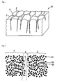
- Fig.1 is a perspective view showing schematically the cross section of the texture of a hydrogen storage material according to the present invention.
- a hydrogen storage material 10 comprising a plurality of column-like first regions 2 and second regions 4 present in the form of a network in between the first regions 2.
- the hydrogen storage material 10 is in the form of a film wherein the second region 4 extends to a thickness direction (the top and bottom directions of Fig.1).
- the hydrogen storage material 10 assumes the form of a film formed according to a gas phase synthesis.
- Fig.2 is a partially enlarged section view of Fig.1
- the first region 2 comprises at least one metal element 24 selected from the group consisting of Ti, Zr, Hf and Y present in an amorphous carbon structure wherein carbon atoms 20 are randomly bonded to each other.
- Amorphous carbon is called by various names such as non-crystalline carbon, diamond-like carbon, glassy carbon, etc. However, these terms are not clearly distinguished from each other.
- amorphous carbon is a solid wherein carbon atoms are bonded to each other in the form of a network, and it has no periodic atomic arrangement of a long distance as in the so-called crystal structure.
- Metal element 24 easily produces a hydride. It is believed that the metal element 24 can combine with a hydrogen atom 22 which penetrated into a hydrogen storage material 10 to form, for example, a metallic hydride or an interstitial hydride whereby a large amount of hydrogen is stored within the hydrogen storage material 10.
- This metal element is Ti, Zr, Hf or Y. They can be included singly or in a combination of two or more. It is preferable that the content of the metal element relative to the hydrogen storage material 10 is from 0.02 to 30 atomic %. When the content of the metal element is under 0.02 atomic %, the hydrogen storage material 10 can not store a satisfactory amount of hydrogen.
- the content of the metal element is from 1 to 15 atomic %.
- the second region 4 is composed of an amorphous carbon having a density lower than that of the first region 2. This amorphous carbon is as described with respect to the first region 2.
- the difference in density between the second region 4 and the first region 2 is not particularly restricted. However, it is preferable that the second region 4 has a density lower in a proportion of from 10 to 40 % than that of the first region 2. When this density difference is under 10 %, it is believed that the second region does not function as an adsorption /desorption site as described hereinafter, so that the repeating properties of hydrogen occlusion / release degrade.
- the density difference is in excess of 40 %, the proportion of a first region which becomes a hydrogen storage site is low so that the hydrogen storage amount decreases.
- the method of determining a difference in density between a first region and a second region includes a process of obtaining a difference in energy absorption in response to a difference of density according to EELS (Electron Energy Loss Spectroscopy).
- EELS Electro Energy Loss Spectroscopy
- the density of the entire hydrogen storage material (an average value of the densities of a first region and a second region) varies with the content of a metal element. For example, it is on the order of from 1.4 to 2.2 g/cm 3 in a metal element-free state. Further, the proportion of the volume of the second region relative to the first region present in the entire hydrogen storage material is not particularly restricted. When the thickness of the hydrogen storage material is on the order of 1 ⁇ m, the volume of a second region in the surface layer portion of the material is on the order of 20 % or less relative to that of the first region.
- the void between a first region 2 and a first region 2, that is, the width of a second region 4 in the left and right directions of Fig.2 is not particularly restricted but can be on the order of, for example, from 1 nm to several nm. Further, when the hydrogen storage material of the present invention is formed into a film according to a gas phase synthesis as described hereinafter, the more the thickness of the film, the larger the width of the second region.
- the second region 4 has a density lower than that of the first region 2.
- the hydrogen 22 occluded in a storage site in the vicinity of the metal element 24 is desorbed from this storage site to migrate within the hydrogen storage material, it is believed that it migrates through the second region 4 easy for it to move.
- the hydrogen storage site in the vicinity of the metal element 24 in the first region 2
- the absorption /release site the second region 4
- the change of carbon structure due to the repeating of a hydrogen occlusion / release process is difficult to occur.
- the repeated properties thus, do not deteriorate.
- the hydrogen atom is incorporated from the second region 4 into the hydrogen storage material due to capillary phenomenon whereby thermal and physical hydrogen absorption and desorption can be effected at low temperatures (on the order of 600 K).
- the present invention includes also a case where a void is present in place of the second region 4.
- a void is present, it is believed that the hydrogen stored in the storage site of the first region 2 migrates within the hydrogen storage material through the void easy for it to move whereby an adsorption / release process is effected.
- the width (diameter) of the void, and the volume proportion of the first region relative to the void are substantially the same as in the second region.
- the void width, and the volume percentage of the void relative to the first region tend to increase as compared with a case that a second region is present. It is believed that this tendency is attributable to the fact that according as the width between columns expands, the void is not completely filled with a network of carbon bond so that a clearance forms.
- the second region can be also present in combination with the void.
- the hydrogen storage material of the present invention is prepared in the form of a film, for example, according to a gas phase synthesis as described hereinafter, and a second region (void) extends to a thickness direction of the film, then the hydrogen atom is adsorbed and desorbed in the thickness direction of the film. Therefore, by providing a differential pressure on both sides of a flm, the hydrogen can be easily penetrated into the thickness direction of the film whereby the hydrogen occlusion reaction is accelerated. Further, by occluding hydrogen within a film in a pressurized atmosphere, the hydrogen occlusion reaction can be accelerated.
- a plurality of films can be also used in the form of a stack or a lamination.
- the column structure shown in Fig.1 produces due to the formation of a non uniform solid phase on a base plate from the gas phase when a subject (an amorphous carbon in the present invention) is formed into a film on the base plate according to a gas phase synthesis. That is, once a solid phase of a subject is nonuniformly formed on a base plate to produce an excessive portion of solid phase, a solid phase is subsequently formed predominantly on this portion so that a column structure grows.
- the temperature of a base plate is lowed when using a gas phase synthesis or process gas pressure is raised when using a sputtering process so as to decrease the mobility of an atom.
- the base plate temperature is set at a low value
- the thermal energy of a subject atom deposited on a base plate is absorbed by the base plate so that its mobility is decreased.
- the process gas pressure is set at a high value
- the subject atom collides against a process gas before reaching a base plate so that the proportion of losing energy is high.
- the gas phase synthesis used in the process for preparation of the present invention can be any physical vapor deposition (PVD) method.
- PVD physical vapor deposition
- a combination process of a PVD principle with a chemical deposition such as, for example, reactive sputtering, etc.
- the shape and type of a base materials when using a gas phase synthesis are not particularly restricted.
- a silicon (Si) base plate can be used.
- the target used in a gas phase synthesis one can use any source of carbon containing a metal element to form a film composed of an amorphous carbon.
- a calcined graphite can be used, and a chip of metal element can be disposed on or built in this calcined graphite can be used as a target described above.
- the base plate temperature is preferably 473 K or less, and more preferably ordinary temperature or less.
- the lower limit value of the base plate temperature is not particularly restricted.
- the base plate can be cooled with water to a temperature of the order of from 0 to 10 °C (from 273 to 283 K) or to a temperature of the order of a liquid nitrogen temperature (77 K). The point is, the base plate temperature can be determined according to performances of deposition apparatuses, production conditions, and the like.
- a process gas pressure of 1.33322 Pa or more it is necessary to use a process gas pressure of 1.33322 Pa or more. Then, the process gas is ionized in a sputtering apparatus, and collides against a target to sputter a target atom which is then deposited on a base plate.
- Ar is used as the process gas. If the process gas pressure is under 1.33322 Pa, a non-uniform solid phase does not thoroughly form on the base plate, and the density of a second region becomes high or the distance between first regions become small. Thus, the second region is difficult to function as an adsorption / desorption site so that the repeating properties of hydrogen occlusion /release are susceptible to deterioration.
- the process gas pressure is 1.99983 Pa or more. However, when the process gas pressure is too high, it is difficult to form a film. Therefore, it is preferred to use, for example, a process gas pressure not much exceeding about 6.6661 Pa.
- a magnetron sputtering apparatus was equipped with a Si base plate and a target.
- the target comprises a commercial disc-type calcined graphite as a carbon source, on the surface of which have been disposed a plurality of Ti, Zr, Hf or Y small pieces having a corner of 5 mm which arranged concentrically.
- the Si base plate was mounted on a copper-made base stand and the base plate was maintained at about 10°C(283K) by cooling the base stand with water.
- Ar was used as the process gas, and the gas pressure was 1.99983 Pa.
- a hydrogen storage material (sample) was prepared by forming an amorphous carbon film up to a thickness of 2 ⁇ m on the base plate.
- Ti small pieces were used, it was designated as working example 1.
- Y small pieces were used, it was designated as working example 2.
- Zr small pieces were used, it was designated as working example 3.
- Hf small pieces were used, it was designated as working example 4.
- the content of Ti(or Zr, Hf, Y) present in the hydrogen storage material was controlled by varying the distance of the small pieces from the center of the calcined graphite. In a word, the distribution of plasma density when sputtering is highest at a position remote by a given distance from the center of the calcined graphite. Thus, when the small pieces were disposed at the place nearest to this position, the content of Ti(or Zr, Hf, Y) is highest.
- Figs.3 to 6 show photographs of the texture of a film according to working example 1.
- Figs.3 and 5 are TEM (Transmission Electron Microscope) images as seen from the surface direction of the film.
- Fig. 4 is a TEM image as seen from the direction perpendicular to the film surface (the cross section of the film). In these figures, the white portion indicates a second region and the black portion a first region, respectively. These TEM images were photographed at an accelerated voltage of 200 kV with the use of a field emission transmission electron microscope (Type: Hf-2000) manufactured by Hitachi Co., Ltd.
- Type: Hf-2000 field emission transmission electron microscope
- Fig. 6 is an EF (Energy Filter) image showing a Ti distribution state in the observed zone of the same scale as in Fig. 5.
- the white portion is a region wherein Ti is present.
- EELS Electro Energy Loss Spectroscopy
- the density of a second region is about 10 % lower than that of a first region.
- the EF image an image obtained by the energy resolution, in a width of 3 eV, of an energy zone of from 13 eV to 28 eV was evaluated.
- the density of a second region is about 10 to 40 % lower than that of a first region.
- the texture photographs (TEM photographs of the plane and the cross section) of Figs. 3 and 4 were subjected to an image analysis. As a result, with respect to working example 1, it was estimated that the volume proportion of a second region present in the hydrogen storage material is about 7 %.
- Comparative example 3 is a sample wherein a calcined graphite by itself is used as the target, a mixed gas of 80 % of Ar and 20 % of methane is used as the process gas, and hydrogen is included at about 40 atomic % in the film formation.
- Comparative example 4 is a sample obtained by the film formation under the same conditions as in working example 1 with the exception that the Ti content of the hydrogen storage material is 35 atomic %.
- Comparative example 5 is a sample obtained by the film formation under the same conditions as in working example 1 with the exception that the base plate temperature is 600°C(873K).
- Comparative example 6 is a sample obtained by the film formation under the same conditions as in working example 1 with the exception that the process gas pressure is a lower pressure (0.66661 Pa).
- any of these samples was placed in a vacuum container which was then subjected to vacuum suction up to the extent of 0.1 Pa. Thereafter, it was exposed to a hydrogen gas at room temperature under 0.3 MPa to occlude hydrogen therein. After the exposure, the hydrogen occlusion amount of the sample was determined according to an ERDA (Elastic Recoil Detection Analysis) method using a Rutherford back scattering determination apparatus. The determination was carried out by irradiating a sample with a helium ion (He + ) beam at 2,300 keV, and then determining the spectrum at a scattering angle of 30°. This ERDA method is also called HFS (Hydrogen Forward Spectrometry). Then, this sample was heated up to 773 K and the release starting temperature of hydrogen was determined by means of a Thermal Desorption Spectroscopy (EMD-WA1400 manufactured by Electric Science Co., Ltd).
- EMD-WA1400 Thermal Desorption Spectroscopy
- the working examples illustrate that not only the initial hydrogen occlusion amount is high but also the hydrogen occlusion amount after the repeated occlusion / release process is high (more than 10 at %) so that the deterioration of the repeating properties of hydrogen occlusion / release can be suppressed Further, in the working examples, it is found that the release starting temperature of hydrogen is lower, ie., 600 K so that the hydrogen is easy to release.
- the hydrogen storage materials of the present invention comprise a first region composed primarily of an amorphous carbon containing at least one metal element selected from the group consisting of Ti, Zr, Hf and Y, and a second region composed primarily of an amorphous carbon having a density lower than that of the first region, they provide a high hydrogen occlusion amount per weight and excellent hydrogen occlusion / release properties, and further can suppress the deterioration of the repeating properties of hydrogen occlusion /release.
- the hydrogen storage materials of the present invention comprise a void present in an amorphous carbon containing at least one metal element selected from the group consisting of Ti, Zr, Hf and Y, they provide a high hydrogen occlusion amount per weight and excellent hydrogen occlusion / release properties, and further can suppress the deterioration of the repeated hydrogen occlusion / release properties
- the process for preparation of hydrogen storage materials comprises forming a film from an amorphous carbon containing at least one metal element selected from the group consisting of Ti, Zr, Hf and Y on the surface of a base material at a temperature of 773 K or less according to a gas phase synthesis, the hydrogen occlusion amount per weight is high and the hydrogen occlusion / release properties are excellent, and also the deterioration of the repeating properties of hydrogen occlusion / release can be suppressed.
- the process for the preparation of hydrogen storage materials comprises forming a film from an amorphous carbon containing at least one metal element selected from the group consisting of Ti, Zr, Hf and Y on the surface of a base material under a process gas pressure of 1.33322 Pa or more according to a sputtering process, the hydrogen occlusion amount per weight is high and the hydrogen occlusion / release properties are excellent, and also the deterioration of the repeating properties of hydrogen occlusion / release can be suppressed.
Landscapes
- Chemical & Material Sciences (AREA)
- Organic Chemistry (AREA)
- Engineering & Computer Science (AREA)
- Chemical Kinetics & Catalysis (AREA)
- Inorganic Chemistry (AREA)
- Combustion & Propulsion (AREA)
- Materials Engineering (AREA)
- Nanotechnology (AREA)
- Geology (AREA)
- General Life Sciences & Earth Sciences (AREA)
- Metallurgy (AREA)
- Environmental & Geological Engineering (AREA)
- Life Sciences & Earth Sciences (AREA)
- Mechanical Engineering (AREA)
- General Physics & Mathematics (AREA)
- Physics & Mathematics (AREA)
- Composite Materials (AREA)
- Condensed Matter Physics & Semiconductors (AREA)
- Crystallography & Structural Chemistry (AREA)
- Analytical Chemistry (AREA)
- Hydrogen, Water And Hydrids (AREA)
- Solid-Sorbent Or Filter-Aiding Compositions (AREA)
- Carbon And Carbon Compounds (AREA)
- Fuel Cell (AREA)
- Physical Vapour Deposition (AREA)
Abstract
Description
- The present invention relates to a hydrogen storage material comprising an amorphous carbon, and a process for preparation of the same.
- In recent years, for using a clean energy, public attention is attracted to a technology utilizing hydrogen in fuel battery and heat pump, and in the storage of a natural energy, etc. In these hydrogen utilizing technologies, hydrogen storage alloys are conventionally used in order to conduct the occlusion and release of hydrogen. However, these hydrogen storage alloys have drawbacks that they are heavy in weight, and when the occlusion / release process is repeated, material degradation occurs and exhibit decreased hydrogen storage capability (deterioration of the repeated properties).
- Under such circumstances, a technology has been recently studied which utilizes a carbon-type material such as carbon nanotube, graphite manofiber, etc. wherein hydrogen is occluded in a void caused from the crystal defect, layer structure etc. of the carbon structure. Particularly, attention is currently focused on amorphous carbon materials which are generally said to exhibit little deterioration of the repeated properties of the hydrogen occlusion / release as described above (for example, refer to Unexamined Japanese Patent Publications(Kokai) 2001-106516 and 2002-28483).
- However, even if these carbon materials are used, it must be said that the improvement of the repeated hydrogen occlusion / release properties are not still satisfactory. This is believed to be attributable to the fact that the hydrogen storage site (the site in which hydrogen is retained) and the adsorption / release site (the site in which hydrogen migration occurs with the desorption of hydrogen from the hydrogen storage site) are on the identical place, and therefore the carbon structure breaks down and changes due to the repeated occlusion / release process.
- The present invention intends to solve the above problems. It is an object of the present invention to provide hydrogen storage materials not only having a high hydrogen storage capability per weight but also exhibiting no deterioration of the properties when the occlusion and release process of hydrogen is repeated, and to provide a process for the preparation of such hydrogen storage materials.
- In order to attain the above object, the hydrogen storage materials of the present invention comprise a first region composed primarily of an amorphous carbon containing at least one metal element selected from the group consisting of Ti, Zr, Hf and Y, and a second region composed primarily of an amorphous carbon having a density lower than that of the first region.
- According to the present invention, it is believed that hydrogen is stored in the vicinity of a metal element such as Ti, Zr, Hf and Y etc. which easily produce a hydride, while the desorbed hydrogen migrates predominantly from a second region of lower density Thus, even if the occlusion and release process of hydrogen is repeated, the properties of the hydrogen storage materials do not deteriorate.
- Alternatively, the hydrogen storage materials of the present invention comprise a void present in an amorphous carbon containing at least one metal element selected from the group consisting of Ti, Zr, Hf and Y.
- According to the present invention, thus, it is believed that hydrogen is stored in the vicinity of a metal element such as Ti, Zr, Hf and Y etc. which easily produce a hydride, while the desorbed hydrogen is migratered predominantly through the void. Accordingly, even if the occlusion and release process of hydrogen is repeated, the properties of the hydrogen storage materials do not deteriorate.
- In the hydrogen storage materials, it is preferred that the content of the metal element is from 0,02 to 30 atomic %.
- It is preferable that the hydrogen storage materials are in the form of a film, and the second region or the void extends to a thickness direction of the film.
- A process for the preparation of hydrogen storage materials according to the present invention comprises providing a source of carbon containing at least one metal element selected from the group consisting of Ti, Zr, Hf and Y, and forming a film composed of an amorphous carbon containing said metal element on the surface of a base material at a temperature of 773 K or less according to a gas phase synthesis.
- Further, a process for the preparation of hydrogen storage materials according to the present invention comprises providing a source of carbon containing at least one metal element selected from the group consisting of Ti, Zr, Hf and Y, and forming a film composed of an amorphous carbon containing said metal element on the surface of a base material under a process gas pressure of 1.33322 Pa or more according to a sputtering process.
-
- Fig.1 is a perspective view showing the cross section of the texture of a hydrogen storage material according to the present invention.
- Fig.2 is a partially enlarged section view of Fig.1.
- Fig.3 is a view showing an image of the texture of a hydrogen storage material according to the present invention.
- Fig.4 is another view showing an image of the texture of a hydrogen storage material according to the present invention.
- Fig.5 is further another view showing an image of the texture of a hydrogen storage material according to the present invention.
- Fig.6 is furthermore another view showing an image of the texture of a hydrogen storage material according to the present invention.
- The following is a description with respect to one embodiment of hydrogen storage materials and processes for the preparation of the same according to the present invention.
- Fig.1 is a perspective view showing schematically the cross section of the texture of a hydrogen storage material according to the present invention. Referring to Fig.1, there is shown a
hydrogen storage material 10 comprising a plurality of column-likefirst regions 2 andsecond regions 4 present in the form of a network in between thefirst regions 2. In this embodiment, thehydrogen storage material 10 is in the form of a film wherein thesecond region 4 extends to a thickness direction (the top and bottom directions of Fig.1). According to the embodiment, thehydrogen storage material 10 assumes the form of a film formed according to a gas phase synthesis. - Fig.2 is a partially enlarged section view of Fig.1 Referring to Fig.2, the
first region 2 comprises at least onemetal element 24 selected from the group consisting of Ti, Zr, Hf and Y present in an amorphous carbon structure whereincarbon atoms 20 are randomly bonded to each other. Amorphous carbon is called by various names such as non-crystalline carbon, diamond-like carbon, glassy carbon, etc. However, these terms are not clearly distinguished from each other. Generally, amorphous carbon is a solid wherein carbon atoms are bonded to each other in the form of a network, and it has no periodic atomic arrangement of a long distance as in the so-called crystal structure. -
Metal element 24 easily produces a hydride. It is believed that themetal element 24 can combine with ahydrogen atom 22 which penetrated into ahydrogen storage material 10 to form, for example, a metallic hydride or an interstitial hydride whereby a large amount of hydrogen is stored within thehydrogen storage material 10. This metal element is Ti, Zr, Hf or Y. They can be included singly or in a combination of two or more. It is preferable that the content of the metal element relative to thehydrogen storage material 10 is from 0.02 to 30 atomic %. When the content of the metal element is under 0.02 atomic %, thehydrogen storage material 10 can not store a satisfactory amount of hydrogen. On the other hand, when the content is above 30 atomic %, a carbide or a carbide-like cluster is formed in between the metal element and carbon atom so that thehydrogen storage material 10 dose not function as an effective hydrogen storage site, or the formation of asecond region 4 as described hereinafter is adversely affected. More preferably, the content of the metal element is from 1 to 15 atomic %. - On the other hand, the
second region 4 is composed of an amorphous carbon having a density lower than that of thefirst region 2. This amorphous carbon is as described with respect to thefirst region 2. The difference in density between thesecond region 4 and thefirst region 2 is not particularly restricted. However, it is preferable that thesecond region 4 has a density lower in a proportion of from 10 to 40 % than that of thefirst region 2. When this density difference is under 10 %, it is believed that the second region does not function as an adsorption /desorption site as described hereinafter, so that the repeating properties of hydrogen occlusion / release degrade. On the other hand, when the density difference is in excess of 40 %, the proportion of a first region which becomes a hydrogen storage site is low so that the hydrogen storage amount decreases. - The method of determining a difference in density between a first region and a second region includes a process of obtaining a difference in energy absorption in response to a difference of density according to EELS (Electron Energy Loss Spectroscopy).
- The density of the entire hydrogen storage material (an average value of the densities of a first region and a second region) varies with the content of a metal element. For example, it is on the order of from 1.4 to 2.2 g/cm3 in a metal element-free state. Further, the proportion of the volume of the second region relative to the first region present in the entire hydrogen storage material is not particularly restricted. When the thickness of the hydrogen storage material is on the order of 1µm, the volume of a second region in the surface layer portion of the material is on the order of 20 % or less relative to that of the first region.
- The void between a
first region 2 and afirst region 2, that is, the width of asecond region 4 in the left and right directions of Fig.2 is not particularly restricted but can be on the order of, for example, from 1 nm to several nm. Further, when the hydrogen storage material of the present invention is formed into a film according to a gas phase synthesis as described hereinafter, the more the thickness of the film, the larger the width of the second region. - As stated above, the
second region 4 has a density lower than that of thefirst region 2. Thus, when thehydrogen 22 occluded in a storage site in the vicinity of themetal element 24 is desorbed from this storage site to migrate within the hydrogen storage material, it is believed that it migrates through thesecond region 4 easy for it to move. For this reason, it is considered that the hydrogen storage site (in the vicinity of themetal element 24 in the first region 2 ) differs from the absorption /release site (the second region 4 ) so that the change of carbon structure due to the repeating of a hydrogen occlusion / release process is difficult to occur. The repeated properties, thus, do not deteriorate. Further, the hydrogen atom is incorporated from thesecond region 4 into the hydrogen storage material due to capillary phenomenon whereby thermal and physical hydrogen absorption and desorption can be effected at low temperatures (on the order of 600 K). - In the above embodiment, we describe a case that a
second region 4 is lower in density than afirst region 2. However, the present invention includes also a case where a void is present in place of thesecond region 4. When a void is present, it is believed that the hydrogen stored in the storage site of thefirst region 2 migrates within the hydrogen storage material through the void easy for it to move whereby an adsorption / release process is effected. The width (diameter) of the void, and the volume proportion of the first region relative to the void are substantially the same as in the second region. However, the void width, and the volume percentage of the void relative to the first region tend to increase as compared with a case that a second region is present. It is believed that this tendency is attributable to the fact that according as the width between columns expands, the void is not completely filled with a network of carbon bond so that a clearance forms. Alternatively, the second region can be also present in combination with the void. - When the hydrogen storage material of the present invention is prepared in the form of a film, for example, according to a gas phase synthesis as described hereinafter, and a second region (void) extends to a thickness direction of the film, then the hydrogen atom is adsorbed and desorbed in the thickness direction of the film. Therefore, by providing a differential pressure on both sides of a flm, the hydrogen can be easily penetrated into the thickness direction of the film whereby the hydrogen occlusion reaction is accelerated. Further, by occluding hydrogen within a film in a pressurized atmosphere, the hydrogen occlusion reaction can be accelerated. When the hydrogen storage material is used in the form of a film, a plurality of films can be also used in the form of a stack or a lamination.
- Next, we will describe one embodiment of the processes for preparation of hydrogen storage materials to which the present invention relates. First, it is known that the column structure shown in Fig.1 produces due to the formation of a non uniform solid phase on a base plate from the gas phase when a subject (an amorphous carbon in the present invention) is formed into a film on the base plate according to a gas phase synthesis. That is, once a solid phase of a subject is nonuniformly formed on a base plate to produce an excessive portion of solid phase, a solid phase is subsequently formed predominantly on this portion so that a column structure grows.
- In the processes for preparation of the present invention, accordingly, it is essential to use a gas phase synthesis. Further, in order to develop this column structure, it is good to decrease the mobility of a subject atom deposited on a base plate. That is, when the mobility of a subject atom is high, a thermal motion is caused on a base plate, and some atoms formed, in a solid phase state, on the base plate are physically spattered so that the formation of a uniform solid phase is promoted. Thus it is difficult to form a non-uniform solid phase.
- In the processes for preparation of the present invention, the temperature of a base plate is lowed when using a gas phase synthesis or process gas pressure is raised when using a sputtering process so as to decrease the mobility of an atom. When the base plate temperature is set at a low value, the thermal energy of a subject atom deposited on a base plate is absorbed by the base plate so that its mobility is decreased. On the other hand, when the process gas pressure is set at a high value, the subject atom collides against a process gas before reaching a base plate so that the proportion of losing energy is high.
- The gas phase synthesis used in the process for preparation of the present invention can be any physical vapor deposition (PVD) method. For example, vacuum deposition, sputtering, ion plating, ion beam evaporation, etc. can be used. Further, a combination process of a PVD principle with a chemical deposition such as, for example, reactive sputtering, etc. can be also used. The shape and type of a base materials when using a gas phase synthesis are not particularly restricted. For example, a silicon (Si) base plate can be used. As the target used in a gas phase synthesis, one can use any source of carbon containing a metal element to form a film composed of an amorphous carbon. As such a carbon source, for example, a calcined graphite can be used, and a chip of metal element can be disposed on or built in this calcined graphite can be used as a target described above.
- According to a process for preparation of the first present invention, it is necessary to use a base plate temperature of 773 K or less in a gas phase synthesis. When the base plate temperature is in excess of 773 K, not only does the above column structure not satisfactorily grow but also the amorphous carbon can not form into a film. The base plate temperature is preferably 473 K or less, and more preferably ordinary temperature or less. The lower limit value of the base plate temperature is not particularly restricted. The base plate can be cooled with water to a temperature of the order of from 0 to 10 °C (from 273 to 283 K) or to a temperature of the order of a liquid nitrogen temperature (77 K). The point is, the base plate temperature can be determined according to performances of deposition apparatuses, production conditions, and the like.
- According to a process for preparation of the second present invention using a sputtering process, it is necessary to use a process gas pressure of 1.33322 Pa or more. Then, the process gas is ionized in a sputtering apparatus, and collides against a target to sputter a target atom which is then deposited on a base plate. For example, Ar is used as the process gas. If the process gas pressure is under 1.33322 Pa, a non-uniform solid phase does not thoroughly form on the base plate, and the density of a second region becomes high or the distance between first regions become small. Thus, the second region is difficult to function as an adsorption / desorption site so that the repeating properties of hydrogen occlusion /release are susceptible to deterioration. Preferably, the process gas pressure is 1.99983 Pa or more. However, when the process gas pressure is too high, it is difficult to form a film. Therefore, it is preferred to use, for example, a process gas pressure not much exceeding about 6.6661 Pa.
- A magnetron sputtering apparatus was equipped with a Si base plate and a target. The target comprises a commercial disc-type calcined graphite as a carbon source, on the surface of which have been disposed a plurality of Ti, Zr, Hf or Y small pieces having a corner of 5 mm which arranged concentrically. The Si base plate was mounted on a copper-made base stand and the base plate was maintained at about 10°C(283K) by cooling the base stand with water. Ar was used as the process gas, and the gas pressure was 1.99983 Pa. A hydrogen storage material (sample) was prepared by forming an amorphous carbon film up to a thickness of 2 µm on the base plate. In a case that Ti small pieces were used, it was designated as working example 1. In a case that Y small pieces were used, it was designated as working example 2. In a case that Zr small pieces were used, it was designated as working example 3. In a case that Hf small pieces were used, it was designated as working example 4. The content of Ti(or Zr, Hf, Y) present in the hydrogen storage material was controlled by varying the distance of the small pieces from the center of the calcined graphite. In a word, the distribution of plasma density when sputtering is highest at a position remote by a given distance from the center of the calcined graphite. Thus, when the small pieces were disposed at the place nearest to this position, the content of Ti(or Zr, Hf, Y) is highest.
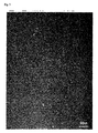
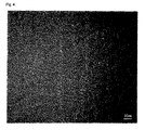
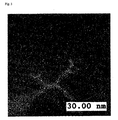
- Figs.3 to 6 show photographs of the texture of a film according to working example 1. Figs.3 and 5 are TEM (Transmission Electron Microscope) images as seen from the surface direction of the film. Fig. 4 is a TEM image as seen from the direction perpendicular to the film surface (the cross section of the film). In these figures, the white portion indicates a second region and the black portion a first region, respectively. These TEM images were photographed at an accelerated voltage of 200 kV with the use of a field emission transmission electron microscope (Type: Hf-2000) manufactured by Hitachi Co., Ltd.
- Fig. 6 is an EF (Energy Filter) image showing a Ti distribution state in the observed zone of the same scale as in Fig. 5. In Fig. 6, the white portion is a region wherein Ti is present. According to EELS (Electron Energy Loss Spectroscopy), a proportion of the density of a second region relative to that of a first region was obtained. The photographing and EELS analysis of the EF image were carried out with the use of an apparatus (Type: Gatan Imaging Filter (GIF) model 678) manufactured by GATAN.
- In the EELS determination, by obtaining a ratio of the spectrum intensity to the zero-loss spectrum intensity of the entire EELS, and also by obtaining a shift amount (on the order of~1eV) of the π+σ peak of carbon in a plasmon loss zone, it was estimated that the density of a second region is about 10 % lower than that of a first region. With respect to the EF image, an image obtained by the energy resolution, in a width of 3 eV, of an energy zone of from 13 eV to 28 eV was evaluated. As a result, it was estimated that the density of a second region is about 10 to 40 % lower than that of a first region. Further, the texture photographs (TEM photographs of the plane and the cross section) of Figs. 3 and 4 were subjected to an image analysis. As a result, with respect to working example 1, it was estimated that the volume proportion of a second region present in the hydrogen storage material is about 7 %.
- By comparison, a sample was obtained wherein a calcined graphite by itself is used as the target and Ti or Y is not included in the hydrogen storage material. This sample is designated as comparative example 1. Further, a sample having no column structure was also obtained wherein a calcined graphite by itself is used as the target and a bias voltage of 100 V direct current is applied to the base plate when sputtering. This sample is designated as comparative example 2. Comparative example 3 is a sample wherein a calcined graphite by itself is used as the target, a mixed gas of 80 % of Ar and 20 % of methane is used as the process gas, and hydrogen is included at about 40 atomic % in the film formation. Comparative example 4 is a sample obtained by the film formation under the same conditions as in working example 1 with the exception that the Ti content of the hydrogen storage material is 35 atomic %. Comparative example 5 is a sample obtained by the film formation under the same conditions as in working example 1 with the exception that the base plate temperature is 600°C(873K). Comparative example 6 is a sample obtained by the film formation under the same conditions as in working example 1 with the exception that the process gas pressure is a lower pressure (0.66661 Pa).
- Any of these samples was placed in a vacuum container which was then subjected to vacuum suction up to the extent of 0.1 Pa. Thereafter, it was exposed to a hydrogen gas at room temperature under 0.3 MPa to occlude hydrogen therein. After the exposure, the hydrogen occlusion amount of the sample was determined according to an ERDA (Elastic Recoil Detection Analysis) method using a Rutherford back scattering determination apparatus. The determination was carried out by irradiating a sample with a helium ion (He+) beam at 2,300 keV, and then determining the spectrum at a scattering angle of 30°. This ERDA method is also called HFS (Hydrogen Forward Spectrometry). Then, this sample was heated up to 773 K and the release starting temperature of hydrogen was determined by means of a Thermal Desorption Spectroscopy (EMD-WA1400 manufactured by Electric Science Co., Ltd).
- After the determination of the initial hydrogen occlusion amount as described above, 4 cycles of vacuum suction and exposure to hydrogen were likewise conducted. Thus, a total of 5 cycles of an occlusion / release process was repeated. After these five cycles, the hydrogen occlusion amount was determined according to an ERDA method. The results thus obtained are shown in the following table.
Table Element used Content (wt. %) Base plate temperature (K) Process gas pressure (Pa) Release starting temperature of hydrogen (K) Initial hydrogen occlusion amount (at %) Hydrogen occlusion amount after repeating (at %) Working example 1 Ti 12.5 283 1.99983 600 14.0 13.0 Working example 2 Y 3.0 283 1.99983 600 16.0 16.0 Working example 3 Zr 8.0 283 1.99983 600 13.6 13.2 Working example 4 Hf 26.0 283 1.99983 600 12.5 10.8 Comparative example 1 - - 283 1.99983 600 2.0 5.0 Comparative example 2 - - 283 1.99983 Not determined 0.0 0.0 Comparative example 3 - - 283 1,99983 850 40.0 0.0 Comparative example 4 Ti 35.0 283 1.99983 Not determined 0.2 0.1 Comparative example 5 Ti 12.5 850 1.99983 Not determined 0.0 0.0 Comparative example 6 Ti 12.5 283 0.66661 650 1.2 0.7 - As is obvious from the Table, the working examples illustrate that not only the initial hydrogen occlusion amount is high but also the hydrogen occlusion amount after the repeated occlusion / release process is high (more than 10 at %) so that the deterioration of the repeating properties of hydrogen occlusion / release can be suppressed Further, in the working examples, it is found that the release starting temperature of hydrogen is lower, ie., 600 K so that the hydrogen is easy to release.
- On the other hand, in case of comparative example 1 wherein Ti, Zr, Hf or Ni is not included in a film and comparative 2 wherein a column structure is not formed therein, both illustrate that not only the initial hydrogen occlusion amount but also the hydrogen occlusion amount after the repeated occlusion / release process is low. Further, in case of comparative example 3 wherein hydrogen is included in a film when formed, it illustrates that the hydrogen occlusion amount after the repeated occlusion /release process is likewise low. From these date, it is obvious that the present invention provides advantageous results by including Ti, Zr, Hf or Ni in a film and forming a column structure therein.
- In case of comparative example 4 wherein the content of Ti is 35 atomic %, it is shown that not only the initial hydrogen occlusion amount but also the hydrogen occlusion amount after the repeated occlusion / release process is low. In this comparative example 4, when XRD (X-ray diffraction) was carried out, it was found that the Ti incorporated in the film forms a carbide (TiC). In case of comparative example 5 wherein the base plate temperature in the film formation is 850 K and comparative example 6 wherein the process gas pressure is 0.6661 Pa, both illustrate that not only the initial hydrogen occlusion amount but also the hydrogen occlusion amount after the repeated occlusion / release process is low.
- As is obvious from the above, since the hydrogen storage materials of the present invention comprise a first region composed primarily of an amorphous carbon containing at least one metal element selected from the group consisting of Ti, Zr, Hf and Y, and a second region composed primarily of an amorphous carbon having a density lower than that of the first region, they provide a high hydrogen occlusion amount per weight and excellent hydrogen occlusion / release properties, and further can suppress the deterioration of the repeating properties of hydrogen occlusion /release.
- Further, since the hydrogen storage materials of the present invention comprise a void present in an amorphous carbon containing at least one metal element selected from the group consisting of Ti, Zr, Hf and Y, they provide a high hydrogen occlusion amount per weight and excellent hydrogen occlusion / release properties, and further can suppress the deterioration of the repeated hydrogen occlusion / release properties
- Further, since the process for preparation of hydrogen storage materials according to the present invention comprises forming a film from an amorphous carbon containing at least one metal element selected from the group consisting of Ti, Zr, Hf and Y on the surface of a base material at a temperature of 773 K or less according to a gas phase synthesis, the hydrogen occlusion amount per weight is high and the hydrogen occlusion / release properties are excellent, and also the deterioration of the repeating properties of hydrogen occlusion / release can be suppressed.
- Further, since the process for the preparation of hydrogen storage materials according to the present invention comprises forming a film from an amorphous carbon containing at least one metal element selected from the group consisting of Ti, Zr, Hf and Y on the surface of a base material under a process gas pressure of 1.33322 Pa or more according to a sputtering process, the hydrogen occlusion amount per weight is high and the hydrogen occlusion / release properties are excellent, and also the deterioration of the repeating properties of hydrogen occlusion / release can be suppressed.
Claims (6)
- A hydrogen storage material comprising a first region composed primarily of an amorphous carbon containing at least one metal element selected from the group consisting of Ti, Zr, Hf and Y, and a second region composed primarily of an amorphous carbon having a density lower than that of the first region.
- A hydrogen storage material comprising a void present in an amorphous carbon containing at least one metal element selected from the group consisting of Ti, Zr, Hf and Y.
- The hydrogen storage material of claim 1 or 2 wherein the content of the metal element is from 0.02 to 30 atomic %.
- The hydrogen storage material of any one of claims 1 to 3 which is in the form of a film, and wherein the second region or the void extends to a thickness direction of the film.
- A process for the preparation of hydrogen storage materials which comprises providing a source of carbon containing at least one metal element selected from the group consisting of Ti, Zr, Hf and Y, and forming a film composed of an amorphous carbon containing said metal element on the surface of a base material at a temperature of 773 K or less according to a gas phase synthesis.
- A process for the preparation of hydrogen storage materials which comprises providing a source of carbon containing at least one metal element selected from the group consisting of Ti, Zr, Hf and Y, and forming a film composed of an amorphous carbon containing said metal element on the surface of a base material under a process gas pressure of 1.33322 Pa or more according to a sputtering process.
Applications Claiming Priority (2)
| Application Number | Priority Date | Filing Date | Title |
|---|---|---|---|
| JP2003023697A JP4370373B2 (en) | 2003-01-31 | 2003-01-31 | Hydrogen storage material and manufacturing method thereof |
| PCT/JP2004/000564 WO2004067166A1 (en) | 2003-01-31 | 2004-01-22 | Hydrogen storage material and method for producing same |
Publications (2)
| Publication Number | Publication Date |
|---|---|
| EP1632285A1 true EP1632285A1 (en) | 2006-03-08 |
| EP1632285A4 EP1632285A4 (en) | 2011-04-20 |
Family
ID=32820734
Family Applications (1)
| Application Number | Title | Priority Date | Filing Date |
|---|---|---|---|
| EP04704364A Withdrawn EP1632285A4 (en) | 2003-01-31 | 2004-01-22 | HYDROGEN STORAGE MATERIAL AND PROCESS FOR PRODUCING THE SAME |
Country Status (7)
| Country | Link |
|---|---|
| US (1) | US8178471B2 (en) |
| EP (1) | EP1632285A4 (en) |
| JP (1) | JP4370373B2 (en) |
| KR (1) | KR100659143B1 (en) |
| CN (1) | CN100395016C (en) |
| CA (1) | CA2508562C (en) |
| WO (1) | WO2004067166A1 (en) |
Families Citing this family (7)
| Publication number | Priority date | Publication date | Assignee | Title |
|---|---|---|---|---|
| JP4370373B2 (en) | 2003-01-31 | 2009-11-25 | 独立行政法人科学技術振興機構 | Hydrogen storage material and manufacturing method thereof |
| WO2005083144A1 (en) * | 2004-02-27 | 2005-09-09 | Japan Science And Technology Agency | Carbonaceous thin film, process for producing the same and member utilizing the thin film |
| US8519489B2 (en) * | 2009-08-26 | 2013-08-27 | Indian Institute Of Technology Madras | Method and apparatus for tunable electrical conductivity |
| JP6482054B2 (en) * | 2014-03-25 | 2019-03-13 | 日産自動車株式会社 | Metal-supported carbon material and method for producing the same |
| CN112226737A (en) * | 2020-09-16 | 2021-01-15 | 上海晶维材料科技有限公司 | A method for improving the performance of titanium zirconium solid solution alloy target by rare earth element alloying |
| KR102660812B1 (en) * | 2021-11-25 | 2024-04-26 | 한국과학기술원 | REVERSIBLE HYDROGEN STORAGE OF AMORPHOUS C60 FULLERENE WITH CARBON DEFECT FACILITATED BY ATOMIC Pt-MEDIATED HYDROGEN SPILLOVER IN AMBIENT CONDITION |
| JP7875154B2 (en) * | 2023-04-27 | 2026-06-17 | 大同メタル工業株式会社 | Sliding member |
Family Cites Families (17)
| Publication number | Priority date | Publication date | Assignee | Title |
|---|---|---|---|---|
| US4503125A (en) * | 1979-10-01 | 1985-03-05 | Xebec, Inc. | Protective overcoating for magnetic recording discs and method for forming the same |
| US4844785A (en) * | 1984-03-27 | 1989-07-04 | Matsushita Electric Industrial Co., Ltd. | Method for deposition of hard carbon film |
| US5478456A (en) * | 1993-10-01 | 1995-12-26 | Minnesota Mining And Manufacturing Company | Sputtering target |
| USH1924H (en) * | 1998-09-15 | 2000-12-05 | The United States Of America As Represented By The Secretary Of The Air Force | Load-adaptive nanocrystalline carbon/amorphous diamond-like carbon composite and preparation method |
| AU6878100A (en) * | 1999-09-09 | 2001-04-10 | Sony Corporation | Carbonaceous material for hydrogen storage and method for preparing the same, and cell and fuel cell |
| JP2001106516A (en) | 1999-10-06 | 2001-04-17 | Toyota Central Res & Dev Lab Inc | Hydrogen storage material |
| JP2001200357A (en) * | 2000-01-19 | 2001-07-24 | Nippon Sheet Glass Co Ltd | Film forming apparatus and film forming method |
| CN1100154C (en) | 2000-01-20 | 2003-01-29 | 南开大学 | Hydrogen storage alloy/carbon nanometer tube composite hydrogen storage material |
| JP4730753B2 (en) * | 2000-03-23 | 2011-07-20 | 株式会社神戸製鋼所 | Diamond-like carbon hard multilayer film and members with excellent wear resistance and sliding resistance |
| JP2002028483A (en) | 2000-07-13 | 2002-01-29 | Toyota Central Res & Dev Lab Inc | Hydrogen gas storage material |
| US6596055B2 (en) * | 2000-11-22 | 2003-07-22 | Air Products And Chemicals, Inc. | Hydrogen storage using carbon-metal hybrid compositions |
| JP2002320848A (en) * | 2001-02-23 | 2002-11-05 | Honda Motor Co Ltd | Hydrogen storage material |
| JP2002361076A (en) * | 2001-06-06 | 2002-12-17 | Seiji Motojima | Hydrogen storage material and methods of producing and utilizing the same |
| JP2003013200A (en) | 2001-06-29 | 2003-01-15 | Mitsubishi Heavy Ind Ltd | Hard carbon film and method for producing the same |
| JP2003165701A (en) | 2001-11-27 | 2003-06-10 | Toyota Central Res & Dev Lab Inc | Hydrogen storage material and method for producing the same |
| JP2003321216A (en) | 2002-04-26 | 2003-11-11 | Hitachi Powdered Metals Co Ltd | Graphite-based hydrogen storage material and method for producing the same |
| JP4370373B2 (en) | 2003-01-31 | 2009-11-25 | 独立行政法人科学技術振興機構 | Hydrogen storage material and manufacturing method thereof |
-
2003
- 2003-01-31 JP JP2003023697A patent/JP4370373B2/en not_active Expired - Fee Related
-
2004
- 2004-01-22 US US10/538,470 patent/US8178471B2/en not_active Expired - Fee Related
- 2004-01-22 CN CNB2004800021568A patent/CN100395016C/en not_active Expired - Fee Related
- 2004-01-22 EP EP04704364A patent/EP1632285A4/en not_active Withdrawn
- 2004-01-22 KR KR1020057008886A patent/KR100659143B1/en not_active Expired - Fee Related
- 2004-01-22 CA CA2508562A patent/CA2508562C/en not_active Expired - Fee Related
- 2004-01-22 WO PCT/JP2004/000564 patent/WO2004067166A1/en not_active Ceased
Also Published As
| Publication number | Publication date |
|---|---|
| CN1735455A (en) | 2006-02-15 |
| US8178471B2 (en) | 2012-05-15 |
| CA2508562A1 (en) | 2004-08-12 |
| KR20050085030A (en) | 2005-08-29 |
| US20060014638A1 (en) | 2006-01-19 |
| KR100659143B1 (en) | 2006-12-19 |
| JP2004261632A (en) | 2004-09-24 |
| JP4370373B2 (en) | 2009-11-25 |
| CA2508562C (en) | 2010-03-23 |
| CN100395016C (en) | 2008-06-18 |
| WO2004067166A1 (en) | 2004-08-12 |
| EP1632285A4 (en) | 2011-04-20 |
Similar Documents
| Publication | Publication Date | Title |
|---|---|---|
| JP2844304B2 (en) | Plasma facing material | |
| US7413814B2 (en) | Multilayer getter structures and methods for making same | |
| Christmann et al. | Interaction of inert gases with a nickel (100) surface: I. Adsorption of xenon | |
| Ruckman et al. | Photoemission studies of carbon monoxide on tantalum-supported palladium thin films | |
| JPH10312973A (en) | Ti / TiN / TiN lower layer realizing aluminum interconnect with high {111} orientation | |
| US6585870B1 (en) | Physical vapor deposition targets having crystallographic orientations | |
| US8178471B2 (en) | Hydrogen storage materials and process for the preparation of the same | |
| Pick et al. | Uptake rates for hydrogen by niobium and tantalum: effect of thin metallic overlayers | |
| Oshima et al. | Solid-liquid phase transition of tin particles observed by UHV high resolution transmission electron microscopy: pseudo-crystalline phase | |
| EP0417802A1 (en) | Hydrogen storage body | |
| Wang et al. | Self-assembled Co nanorods in diamond-like carbon thin films synthesized by plasma-assisted magnetron sputtering | |
| Silverman et al. | Lateral interactions in the thermal desorption of H2 from clean Cu/Ni (110) alloy surfaces | |
| KR101290340B1 (en) | graphene manufacturing method using RF sputtering method | |
| WO2005083144A1 (en) | Carbonaceous thin film, process for producing the same and member utilizing the thin film | |
| Nepijko et al. | Transmission electron microscopy study of platinum clusters on Al 2 O 3/NiAl (110) under the influence of electron irradiation | |
| Shen et al. | Reactively sputtered WOxNy films | |
| Andersson et al. | Structure of Fe–Co/Pt (001) superlattices: a realization of tetragonal Fe–Co alloys | |
| Shern et al. | Effect of annealing of Ag ultrathin films on Co/Pt (111) surface | |
| Dinh et al. | GaAs nanostructures and films deposited by a Cu-vapor laser | |
| Pennemann et al. | On the catalytic oxidation of amorphous carbon by Pd and Pd Ag particles | |
| Dorey | Structures and properties of oxygen-aluminium vapour deposits | |
| US6666901B1 (en) | Thermal shock resistant quasicrystalline alloy target | |
| Bondarenko et al. | Influence of surface oxidation on the structure and properties of cold metal cathodes | |
| Lu et al. | Microstructure, stress and optical properties of Ge/C multilayers | |
| Simpson | Nickel-titanium-copper thin films by a DC sputtering system |
Legal Events
| Date | Code | Title | Description |
|---|---|---|---|
| PUAI | Public reference made under article 153(3) epc to a published international application that has entered the european phase |
Free format text: ORIGINAL CODE: 0009012 |
|
| 17P | Request for examination filed |
Effective date: 20050623 |
|
| AK | Designated contracting states |
Kind code of ref document: A1 Designated state(s): DE FR GB IT |
|
| DAX | Request for extension of the european patent (deleted) | ||
| RBV | Designated contracting states (corrected) |
Designated state(s): DE FR GB IT |
|
| A4 | Supplementary search report drawn up and despatched |
Effective date: 20110321 |
|
| RIC1 | Information provided on ipc code assigned before grant |
Ipc: C01B 3/00 20060101ALI20110315BHEP Ipc: C01B 6/02 20060101ALI20110315BHEP Ipc: B01J 20/20 20060101AFI20040813BHEP Ipc: C01B 31/00 20060101ALI20110315BHEP |
|
| 17Q | First examination report despatched |
Effective date: 20110819 |
|
| STAA | Information on the status of an ep patent application or granted ep patent |
Free format text: STATUS: THE APPLICATION IS DEEMED TO BE WITHDRAWN |
|
| 18D | Application deemed to be withdrawn |
Effective date: 20150408 |