EP1632123A1 - Lawn mower - Google Patents
Lawn mower Download PDFInfo
- Publication number
- EP1632123A1 EP1632123A1 EP05255387A EP05255387A EP1632123A1 EP 1632123 A1 EP1632123 A1 EP 1632123A1 EP 05255387 A EP05255387 A EP 05255387A EP 05255387 A EP05255387 A EP 05255387A EP 1632123 A1 EP1632123 A1 EP 1632123A1
- Authority
- EP
- European Patent Office
- Prior art keywords
- cutter housing
- wall
- cutter
- housing
- lawn mower
- Prior art date
- Legal status (The legal status is an assumption and is not a legal conclusion. Google has not performed a legal analysis and makes no representation as to the accuracy of the status listed.)
- Granted
Links
- 230000003014 reinforcing effect Effects 0.000 claims abstract description 24
- 229920003002 synthetic resin Polymers 0.000 claims abstract description 4
- 239000000057 synthetic resin Substances 0.000 claims abstract description 4
- 238000005452 bending Methods 0.000 abstract description 7
- 241001494496 Leersia Species 0.000 description 24
- 244000025254 Cannabis sativa Species 0.000 description 20
- 238000005520 cutting process Methods 0.000 description 4
- 229920005989 resin Polymers 0.000 description 4
- 239000011347 resin Substances 0.000 description 4
- 238000002347 injection Methods 0.000 description 3
- 239000007924 injection Substances 0.000 description 3
- 230000033001 locomotion Effects 0.000 description 3
- 230000013011 mating Effects 0.000 description 3
- 241000507379 Coleanthus subtilis Species 0.000 description 2
- 239000000463 material Substances 0.000 description 2
- 230000005540 biological transmission Effects 0.000 description 1
- 238000012423 maintenance Methods 0.000 description 1
- 238000000465 moulding Methods 0.000 description 1
- 239000011148 porous material Substances 0.000 description 1
Images





Classifications
-
- A—HUMAN NECESSITIES
- A01—AGRICULTURE; FORESTRY; ANIMAL HUSBANDRY; HUNTING; TRAPPING; FISHING
- A01D—HARVESTING; MOWING
- A01D34/00—Mowers; Mowing apparatus of harvesters
- A01D34/01—Mowers; Mowing apparatus of harvesters characterised by features relating to the type of cutting apparatus
- A01D34/412—Mowers; Mowing apparatus of harvesters characterised by features relating to the type of cutting apparatus having rotating cutters
- A01D34/63—Mowers; Mowing apparatus of harvesters characterised by features relating to the type of cutting apparatus having rotating cutters having cutters rotating about a vertical axis
- A01D34/81—Casings; Housings
-
- A—HUMAN NECESSITIES
- A01—AGRICULTURE; FORESTRY; ANIMAL HUSBANDRY; HUNTING; TRAPPING; FISHING
- A01D—HARVESTING; MOWING
- A01D2101/00—Lawn-mowers
-
- Y—GENERAL TAGGING OF NEW TECHNOLOGICAL DEVELOPMENTS; GENERAL TAGGING OF CROSS-SECTIONAL TECHNOLOGIES SPANNING OVER SEVERAL SECTIONS OF THE IPC; TECHNICAL SUBJECTS COVERED BY FORMER USPC CROSS-REFERENCE ART COLLECTIONS [XRACs] AND DIGESTS
- Y10—TECHNICAL SUBJECTS COVERED BY FORMER USPC
- Y10S—TECHNICAL SUBJECTS COVERED BY FORMER USPC CROSS-REFERENCE ART COLLECTIONS [XRACs] AND DIGESTS
- Y10S56/00—Harvesters
- Y10S56/20—Blades, reels and guards
Definitions
- This invention relates to a lawn mower in which a cutter housing made of resin is used, a cutter blade is rotated inside this cutter housing, and a grass lawn surface can be cut with this cutter blade.
- the lawn mower 250 of related art shown in Fig. 14 has an engine 252 mounted on the top of a cutter housing 251. As shown in Fig. 15, a cutter blade 254 is attached to the output shaft 253 of the engine 252. A handle 255 (see Fig. 14) extends rearward from the cutter housing 251. Front wheels 256, 256 and rear wheels 257, 257 are attached to the cutter housing 251. The lawn mower 250 travels on these front wheels 256, 256 and rear wheels 257, 257 and cuts grass with the cutter blade 254.
- Flange parts 258, 258 are formed on the sides of the cutter housing 251. These flange parts 258, 258 have multiple reinforcing ribs 259, whereby the impact-resistance of the left and right side faces of the cutter housing 251 is increased.
- a lawn mower has been awaited with which it is possible to increase the length-direction bending rigidity of the cutter housing and it is possible to increase the resistance to impacts from the sides of the cutter housing.
- the present invention provides a lawn mower having a cutter housing, a motive power source mounted on the cutter housing, and a cutter blade attached to the end of the output shaft of the motive power source horizontally and rotatably in a scroll part of the cutter housing, wherein the cutter housing is made of a synthetic resin and has side guard parts respectively on left and right peripheries of the scroll part, each of the side parts is made up of a substantially horizontal guard wall extending outward from the vicinity of a lower end of a side wall of the scroll part and in a front-rear direction, a vertical guard wall extending downward from the horizontal guard wall and in the front-rear direction, and a connecting rib connected between the side wall and the horizontal guard wall and extending in the front-rear direction, and by the side wall, the horizontal guard wall and the connecting rib a hollow reinforcing part is formed in the vicinity of the lower end of the side wall.
- a side guard part made up of a substantially horizontal guard wall extending outward from the lower end vicinity of the side wall of the scroll part and in the front-rear direction, a vertical guard wall extending downward from the horizontal guard wall and in the front-rear direction, and a connecting rib connected between the side wall and the horizontal guard wall and extending in the front-rear direction, a hollow reinforcing part constituted by the side wall, the horizontal guard wall and the connecting rib can be formed in the vicinity of the lower end of the side wall, the resistance of the cutter housing to impacts from the sides can be increased, and the length-direction bending rigidity of the cutter housing can also be increased. Thus, overall rigidity of the lawn mower can be obtained.
- gas is filled into the hollow reinforcing part which is closed.
- a lawn mower 10 constituting a preferred embodiment of the invention shown in Fig. 1 is of a self-propelling type.
- a cutter blade 14 for cutting grass is rotated by an engine 13, which is a motive power source. Cut grass is collected by being carried from a cutter housing 12 by a carrying draft into a grass bag 24.
- Rear wheels 17 are driven by the engine 13.
- the reference number 11 denotes a machine body; 16 front wheels; 18 handle stays; 19 a handle; 21 a handle cover extending across the handle 19; 22 a clutch lever for travel, which clutch-controls motive power transmission from the engine 13 to the rear wheels 17; 23 a grass cover; 25 a clutch lever for clutch-controlling rotational power to the cutter blade 14; 26 a lock lever; 27 a head cover; and 60 a lock mechanism.
- the clutch lever 25 is a lever that simultaneously performs an operation of applying a brake to the cutter blade 14 while stopping the driving of the cutter blade 14, and is sometimes called a BBC control lever because it controls a blade, a brake and a clutch (BBC).
- the engine 13 of the lawn mower 10 is mounted on the top of the cutter housing 12.
- the cutter blade 14 is attached to the output shaft 28 of the engine 13 by way of a clutch mechanism 40.
- the left and right front wheels 16 are disposed at side faces of the front part of the cutter housing 12, and the left and right rear wheels 17 are disposed at side faces of the rear part of the cutter housing 12.
- Left and right handle stays 18 are attached to the side faces of the rear part of the cutter housing 12.
- the handle 19 extends rearward from the rear parts of these handle stays 18, 18.
- the clutch lever 25 is mounted on this handle 19 and controls the clutch mechanism 40.
- the lock lever 26 is mounted in front of the clutch lever 25 and bars an engaging function of the clutch lever.
- the grass bag 24 is removably attached to a rear wall 31 of the cutter housing 12.
- a grass guard 23 is swingably attached to an upper part of the rear wall 31 of the cutter housing 12.
- the grass bag 24 is made of a porous material having air holes, not shown, through which the carrying draft can pass but grass cuttings cannot pass.
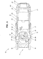
- the clutch mechanism 40 As shown in Fig. 3, with the engine 13 (see Fig. 2) started, the clutch mechanism 40 (see Fig. 2) is switched from an off state to an engaged state by a two-stage motion of shifting the clutch lever 25 to the handle 19 side and then shifting the lock lever 26 forward, to rotate the cutter blade 14, and the clutch lever for travel 22 is shifted to the handle 19 side to rotate the rear wheels 17, 17.
- the cutter blade 14 has blade parts 38, 38 on its leading sides in the rotation direction shown with the arrows A, A, and from these blade parts 38, 38 on its trailing sides in the rotation direction it has air-lifting parts 39, 39 formed so as to curve upward.
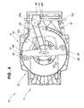
- Fig. 4 shows the underside of the lawn mower 10.
- the cutter blade 14 is covered by the cutter housing 12.
- the cut grass carrying passage 32 for guiding cut grass into the grass bag 24 (see Fig. 2) is formed in the cutter housing 12. This cut grass carrying passage 32 connects with the grass bag 24.
- the reference number 29 denotes a power-transmitting part (a belt); 33 a scroll part provided in the cutter housing 12 for rotatably receiving the cutter blade 14; 52 a drive pulley; 34 a clutch for travel; and 35 a rear wheel axle.
- the output of the engine 13 is transmitted from the drive pulley 52 of the output shaft 28 to a driven pulley 29a by the belt 29, and by way of the driven pulley 29a and the clutch for travel 34 the output of the engine 13 is transmitted to the rear wheel axle 35 and drives the rear wheels 17, 17 (see Fig. 3).
- FIG. 5 shows a mulching work state of the lawn mower.
- Mulching work (mulching mode) is a working mode in which two cutter blades are provided in the cutter housing, grass is cut with these cutter blades, and finely cut grass cuttings are dispersed on the lawn surface (ground surface) so that they are inconspicuous.
- Mulching work is an alternative mode of discharge work, discussed below.
- Discharge work is a working mode in which grass is cut with one cutter blade, and the cut grass is made to pass through the cut grass carrying passage and discharged to outside through the grass cover.
- Bagging work is a working mode in which grass is cut with one cutter blade and the cut grass is made to pass through the cut grass carrying passage and collected in the grass bag.
- the lawn mower 10 of this preferred embodiment is capable of mulching work, discharge work and bagging work (see Fig. 2).
- an upper cutter blade 15 for mulching work is fitted to the output shaft 28 of the engine 13 along with a cutter blade 14 for discharge work and bagging work, and a closing member (not shown) is placed in the cut grass carrying passage 32 (see Fig. 4) for performance of operations.
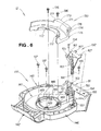
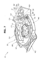
- Fig. 6 and Fig. 7 show a cutter housing 12 according to the illustrated embodiment of the invention in an upside-down state.
- the cutter housing 12 is made up of a housing proper 131 for receiving the cutter blade 14; a bottom member 132, attached to this housing proper 131, for forming the cut grass carrying passage 32 (see Fig. 4); and a scroll guide member 133, attached to the housing proper 131, for forming the scroll part 33 (see Fig. 4).
- This cutter housing 12 is made of a resin material.
- the bottom member 132 is attached to the housing proper 131 by fixing screws 134, 135.
- the scroll guide member 133 is co-fastened to the cutter housing 12 and the engine 13 (see Fig. 1) with fixing screws 136, 136.
- the reference numbers 137, 137 denote fixing screws for fixing the engine 13 to the cutter housing 12.
- the housing proper 131 has a housing concavity 141 forming the cut grass carrying passage 32 and the scroll part 33 shown in Fig. 4.
- a front guard part 142 is formed at the front of this housing concavity 141.
- a rear wall 31 is formed at the rear of the housing concavity 141.
- Left and right side guard parts 145, 146 are formed at the left and right sides of the housing concavity 141.
- the output shaft 28 of the engine 13 and the clutch mechanism 40 shown in Fig. 2 are passed through a top opening 147 formed in the center of the housing concavity 141.
- An engine mount part 148 for the engine 13 to be mounted to is formed around the top opening 147.
- the engine 13 is mounted to the engine mount part 148 using the fixing screws 136, 137 and a plurality of fixing holes 149 formed in the engine mount part 148.
- An inner mounting boss 151 for mounting the bottom member 132 to the housing proper 131 is formed in the housing concavity 141. Also, an outer mounting boss 152 for mounting the bottom member 132 to the housing proper 131 is formed on the right side guard part 146.
- Multiple internal pressure control holes 153 for controlling the internal pressure of the cut grass collecting unit 24 are formed in the left side of the rear wall 31.
- a cut grass carrying passage exit 154 is formed in the right side of the rear wall 31.
- Engaging holes 155, 155 for engaging with the bottom member 132 are also formed in the right side of the rear wall 31.
- the bottom member 132 has a body part 161 for forming the bottom of the cut grass carrying passage 32 (see Fig. 4); an entrance-side reinforced part 163 formed at the front of the body part 161 so that it forms a flange in the shape of an arc of the scroll part 33 (see Fig. 4) and completes a cut grass carrying passage entrance 162 (see Fig.
- an inner mounting part 165 formed at the inner end of this entrance-side reinforced part 163, to be fixed to the inner mounting boss 151; an outer mounting part 166, formed at the outer end of the entrance-side reinforced part 163, to be fixed to the outer mounting boss 152; and projections 167, 167, formed at the rear of the body part 161, to fit in the engaging holes 155, 155 formed in the rear wall 31.
- the entrance-side reinforced part 163 has the function of completing the vertical wall of the scroll part 33.
- the scroll guide member 133 has an arcuate scroll channel 171 through which an approximate sectional U-shape forming the scroll part 33 (see Fig. 4) continues.
- the scroll guide member 133 is co-fastened to the housing proper 131 along with the engine 13 through co-fastening parts 172, 172 formed at the inner periphery of this scroll channel 171.
- a flange part 173 formed on the outer periphery of the scroll channel 171 forms an arcuate flange of the scroll part 33.
- the flange part 173 has a boss part 174 formed at one end 176 of it.
- the boss part 174 is fitted (press-fitted) in the inner mounting part 165 of the bottom member 132.
- a carrying passage side face part 175 forming a part of a side face of the cut grass carrying passage 32 is formed at the end 176 of the scroll channel 171.
- the reference number 177 denotes the other end of the flange part 173.
- the scroll guide member 133 is positioned at the lowest position of the cut grass carrying passage entrance 162 of the cut grass carrying passage 32 and is formed in a shape continuous with the housing proper 131 at the vicinity of the maximum width of the cutter housing 12.
- the cutter housing 12 is divided into the housing proper 131, the bottom member 132 and the scroll guide member 133 like this, simplification of dies for molding the members constituting the cutter housing 12 is achieved and the manufacturability of the cutter housing 12 can be improved.
- the inner mounting part 165 of the bottom member 132 has a through hole 168 for a fixing screw 134 to pass through and a mating tubular part 169 for the boss part 174 of the scroll guide member 133 to mate with.
- the two members that are the bottom member 132 and the scroll guide member 133 can be supported on the one inner mounting boss 151.
- the entrance-side reinforced part 163 of the bottom member 132 and the scroll guide member 133 are assembled in a continuous arc shape so as to allow rotation of the cutter blade 14 (see Fig. 4).
- Fig. 10 shows a housing proper as seen from the underside of a cutter housing according to the illustrated embodiment of the invention.
- the cutter housing 12 has front wheel support parts 198, 198 for supporting the front wheels 16, 16 shown in Fig. 3 formed at its front end and rear wheel support parts 199, 199 for supporting the rear wheels 17, 17 formed at its rear end.
- the front wheel support parts 198, 198 and the rear wheel support parts 199, 199 contribute to an increase in the rigidity of the cutter housing 12.
- a hollow reinforcing part 191 is formed in the front-rear direction of the machine body 11 (see Fig. 2), and this increases the resistance of the cutter housing 12 to impacts from the side and the length-direction bending rigidity of the cutter housing 12. Consequently, when the machine body 11 (see Fig. 2) is turned during mowing work, even when an operation of pushing the handle 19 (see Fig. 2) down and lifting up the front wheels 16, 16 about the rear wheels 17, 17 as a pivot is carried out, bending of the cutter housing 12 is kept to a minimum.
- the right side guard 146 has a structure having a hollow reinforcing part 192 approximately symmetrical with the left side guard part 145, and a detailed description of it will be omitted.
- the reference numbers 197, 197 show gas injection holes for gas injection.
- the left side guard part 145 includes the hollow reinforcing part 191 and a vertical guard wall 195.
- the hollow reinforcing part 191 is made up of the side wall 193 of the scroll part 33 (see Fig. 10), an approximately horizontal guard wall 194 extending outward from the lower end vicinity of the side wall 193 and in the front-rear direction, and a connecting rib 196 interposed between the side wall 193 and the horizontal guard wall 194 and extending in the front-rear direction.
- the vertical guard wall 195 extends downward from the horizontal guard wall 194 and in the front-rear direction.
- a pipe-shaped reinforcing part 191 being constructed to include the vertical guard wall 195 like this, the protrusion of the left side guard part 145 can be made small, the cutter housing 12 (see Fig. 10) can be made slim, and the width of the lawn mower 10 (see Fig. 1) can be made small.
- the cutter housing 12 is a member made of a synthetic resin.
- This cutter housing 12 has side guard parts 145, 146 (see Fig. 10 for 146) on left and right peripheries of a scroll part 33, and each of the left and right side guard parts 145, 146 has an approximately horizontal guard wall 194 extending outward from the lower end vicinity of the side wall 193 of the scroll part 33 and in the front-rear direction, a vertical guard wall 195 extending downward from the horizontal guard wall 194 and in the front-rear direction, and a connecting rib 196 connecting together the side wall 193 and the horizontal guard wall 194 and extending in the front-rear direction, and the side wall 193, the horizontal guard wall 194 and the connecting rib 196 form a hollow reinforcing part 191 at the lower end vicinity of the side wall 193.
- the resistance of the cutter housing 12 to impacts from the side can be increased, and the length-direction bending rigidity of the cutter housing 12 can also be increased. As a result, it is possible to increase the overall rigidity of the lawn mower.
- hollow reinforcing parts 191, 192 were formed on left and right peripheries of the scroll part 33 on the cutter housing 12, as shown in Fig. 10, the invention is not limited to this, and alternatively a hollow reinforcing part may be formed on the front or the rear of the cutter housing, or a hollow reinforcing part may be formed continuously all the way around the cutter housing 12.
Landscapes
- Life Sciences & Earth Sciences (AREA)
- Environmental Sciences (AREA)
- Harvester Elements (AREA)
Abstract
Description
- This invention relates to a lawn mower in which a cutter housing made of resin is used, a cutter blade is rotated inside this cutter housing, and a grass lawn surface can be cut with this cutter blade.
- When work is carried out using a lawn mower, normally, it is carried out with all of four wheels mounted on a cutter housing in contact with the ground. However, sometimes, to mount or dismount a place where there is a step, or to shake cut grass adhered to parts inside the cutter housing off onto the ground surface, a movement of lifting the front wheels about the rear wheels as a pivot is carried out. When this movement is carried out, an external force tending to bend the cutter housing in the length direction acts.
- With respect to an external force of this kind, in a cutter housing made of resin, due to the rigidity and strength characteristics of the material, it is not possible to obtain adequate rigidity and strength.
- In this connection, a lawn mower in which reinforcing ribs are formed in a resin cutter housing to provide the cutter housing with the necessary rigidity has been proposed, for example in JP-UM-B-4-40433.
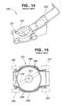
- This lawn mower of related art will now be described on the basis of Fig. 14 and Fig. 15 hereof.
- The
lawn mower 250 of related art shown in Fig. 14 has anengine 252 mounted on the top of acutter housing 251. As shown in Fig. 15, acutter blade 254 is attached to theoutput shaft 253 of theengine 252. A handle 255 (see Fig. 14) extends rearward from thecutter housing 251.Front wheels rear wheels cutter housing 251. Thelawn mower 250 travels on thesefront wheels rear wheels cutter blade 254.Flange parts cutter housing 251. Theseflange parts ribs 259, whereby the impact-resistance of the left and right side faces of thecutter housing 251 is increased. - However, in the
lawn mower 250, because the multiple reinforcingribs 259 are formed on theflange parts cutter housing 251, there has been the shortcoming that they make no contribution to the length-direction bending rigidity of thecutter housing 251. And it has also been the case that mud or cut grass enters between the reinforcingribs 259, and this mud or cut grass has to be removed every time mowing work is carried out, so that the ease of maintenance of thelawn mower 250 is reduced. - Accordingly, a lawn mower has been awaited with which it is possible to increase the length-direction bending rigidity of the cutter housing and it is possible to increase the resistance to impacts from the sides of the cutter housing.
- The present invention provides a lawn mower having a cutter housing, a motive power source mounted on the cutter housing, and a cutter blade attached to the end of the output shaft of the motive power source horizontally and rotatably in a scroll part of the cutter housing, wherein the cutter housing is made of a synthetic resin and has side guard parts respectively on left and right peripheries of the scroll part, each of the side parts is made up of a substantially horizontal guard wall extending outward from the vicinity of a lower end of a side wall of the scroll part and in a front-rear direction, a vertical guard wall extending downward from the horizontal guard wall and in the front-rear direction, and a connecting rib connected between the side wall and the horizontal guard wall and extending in the front-rear direction, and by the side wall, the horizontal guard wall and the connecting rib a hollow reinforcing part is formed in the vicinity of the lower end of the side wall.
- Because on the left and on the right of the cutter housing respectively there is formed a side guard part made up of a substantially horizontal guard wall extending outward from the lower end vicinity of the side wall of the scroll part and in the front-rear direction, a vertical guard wall extending downward from the horizontal guard wall and in the front-rear direction, and a connecting rib connected between the side wall and the horizontal guard wall and extending in the front-rear direction, a hollow reinforcing part constituted by the side wall, the horizontal guard wall and the connecting rib can be formed in the vicinity of the lower end of the side wall, the resistance of the cutter housing to impacts from the sides can be increased, and the length-direction bending rigidity of the cutter housing can also be increased. Thus, overall rigidity of the lawn mower can be obtained.
- Preferably gas is filled into the hollow reinforcing part which is closed.
- Certain preferred embodiments of the invention will now be described in detail, by way of example only, with reference to the accompanying drawings, in which:
- Fig. 1 is a perspective view of a lawn mower according to a preferred embodiment of the invention;
- Fig. 2 is a side view of the lawn mower shown in Fig. 1;
- Fig. 3 is a plan view of the lawn mower shown in Fig. 1;
- Fig. 4 is a view in the direction of the arrow 4 in Fig. 1;
- Fig. 5 is a side view showing a mulching work state of the lawn mower shown in Fig. 1;
- Fig. 6 is an exploded perspective view of a cutter housing according to the illustrated embodiment of the invention;
- Fig. 7 is a perspective view of the cutter housing shown in Fig. 6 in an assembled state;
- Fig. 8 is a sectional view taken along line 8-8 of Fig. 7;
- Fig. 9 is a view in the direction of arrow 9 of Fig. 7;
- Fig. 10 is a bottom view of a housing proper of a cutter housing according to the illustrated embodiment of the invention;
- Fig. 11 is a sectional view taken along line 11-11 of Fig. 10;
- Fig. 12 is a sectional view taken along line 12-12 of Fig. 10;
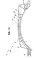
- Fig. 13 is a view showing a side guard part of a housing proper according to the illustrated embodiment of the invention;
- Fig. 14 is a perspective view showing a conventional lawn mower; and
- Fig. 15 is a bottom view of a cutter housing shown in Fig. 14.
- A
lawn mower 10 constituting a preferred embodiment of the invention shown in Fig. 1 is of a self-propelling type. Acutter blade 14 for cutting grass is rotated by anengine 13, which is a motive power source. Cut grass is collected by being carried from acutter housing 12 by a carrying draft into agrass bag 24.Rear wheels 17 are driven by theengine 13. - In the figure, the
reference number 11 denotes a machine body; 16 front wheels; 18 handle stays; 19 a handle; 21 a handle cover extending across thehandle 19; 22 a clutch lever for travel, which clutch-controls motive power transmission from theengine 13 to therear wheels 17; 23 a grass cover; 25 a clutch lever for clutch-controlling rotational power to thecutter blade 14; 26 a lock lever; 27 a head cover; and 60 a lock mechanism. - The
clutch lever 25 is a lever that simultaneously performs an operation of applying a brake to thecutter blade 14 while stopping the driving of thecutter blade 14, and is sometimes called a BBC control lever because it controls a blade, a brake and a clutch (BBC). - As shown in Fig. 2, the
engine 13 of thelawn mower 10 is mounted on the top of thecutter housing 12. Thecutter blade 14 is attached to theoutput shaft 28 of theengine 13 by way of aclutch mechanism 40. The left and rightfront wheels 16 are disposed at side faces of the front part of thecutter housing 12, and the left and rightrear wheels 17 are disposed at side faces of the rear part of thecutter housing 12. Left and right handle stays 18 are attached to the side faces of the rear part of thecutter housing 12. Thehandle 19 extends rearward from the rear parts of these handle stays 18, 18. Theclutch lever 25 is mounted on thishandle 19 and controls theclutch mechanism 40. Thelock lever 26 is mounted in front of theclutch lever 25 and bars an engaging function of the clutch lever. Thegrass bag 24 is removably attached to arear wall 31 of thecutter housing 12. Agrass guard 23 is swingably attached to an upper part of therear wall 31 of thecutter housing 12. - The
grass bag 24 is made of a porous material having air holes, not shown, through which the carrying draft can pass but grass cuttings cannot pass. - As shown in Fig. 3, with the engine 13 (see Fig. 2) started, the clutch mechanism 40 (see Fig. 2) is switched from an off state to an engaged state by a two-stage motion of shifting the
clutch lever 25 to thehandle 19 side and then shifting thelock lever 26 forward, to rotate thecutter blade 14, and the clutch lever fortravel 22 is shifted to thehandle 19 side to rotate therear wheels - The
cutter blade 14 hasblade parts blade parts parts - That is, as the
cutter blade 14 rotates, grass on the ground surface is caused to stand up by a negative pressure arising on the undersides of the air-liftingparts blade parts parts cutter blade 14, and with this swirling airflow as a carrying draft the grass cuttings are fed together with the carrying draft through a cutgrass carrying passage 32 into thegrass bag 24 as shown by the arrow B. - Fig. 4 shows the underside of the
lawn mower 10. - The
cutter blade 14 is covered by thecutter housing 12. The cutgrass carrying passage 32 for guiding cut grass into the grass bag 24 (see Fig. 2) is formed in thecutter housing 12. This cutgrass carrying passage 32 connects with thegrass bag 24. - The
reference number 29 denotes a power-transmitting part (a belt); 33 a scroll part provided in thecutter housing 12 for rotatably receiving thecutter blade 14; 52 a drive pulley; 34 a clutch for travel; and 35 a rear wheel axle. - In the
lawn mower 10, the output of theengine 13 is transmitted from thedrive pulley 52 of theoutput shaft 28 to a drivenpulley 29a by thebelt 29, and by way of the drivenpulley 29a and the clutch fortravel 34 the output of theengine 13 is transmitted to therear wheel axle 35 and drives therear wheels 17, 17 (see Fig. 3). - Fig. 5 shows a mulching work state of the lawn mower. Mulching work (mulching mode) is a working mode in which two cutter blades are provided in the cutter housing, grass is cut with these cutter blades, and finely cut grass cuttings are dispersed on the lawn surface (ground surface) so that they are inconspicuous. Mulching work is an alternative mode of discharge work, discussed below.
- Discharge work (discharge mode) is a working mode in which grass is cut with one cutter blade, and the cut grass is made to pass through the cut grass carrying passage and discharged to outside through the grass cover.
- Bagging work (bagging mode) is a working mode in which grass is cut with one cutter blade and the cut grass is made to pass through the cut grass carrying passage and collected in the grass bag.
- That is, the
lawn mower 10 of this preferred embodiment is capable of mulching work, discharge work and bagging work (see Fig. 2). When mulching work is to be done, anupper cutter blade 15 for mulching work is fitted to theoutput shaft 28 of theengine 13 along with acutter blade 14 for discharge work and bagging work, and a closing member (not shown) is placed in the cut grass carrying passage 32 (see Fig. 4) for performance of operations. - Fig. 6 and Fig. 7 show a
cutter housing 12 according to the illustrated embodiment of the invention in an upside-down state. - The
cutter housing 12 is made up of a housing proper 131 for receiving thecutter blade 14; abottom member 132, attached to this housing proper 131, for forming the cut grass carrying passage 32 (see Fig. 4); and ascroll guide member 133, attached to the housing proper 131, for forming the scroll part 33 (see Fig. 4). Thiscutter housing 12 is made of a resin material. - The
bottom member 132 is attached to the housing proper 131 by fixingscrews scroll guide member 133 is co-fastened to thecutter housing 12 and the engine 13 (see Fig. 1) with fixingscrews - The
reference numbers engine 13 to thecutter housing 12. - The housing proper 131 has a
housing concavity 141 forming the cutgrass carrying passage 32 and thescroll part 33 shown in Fig. 4. Afront guard part 142 is formed at the front of thishousing concavity 141. Arear wall 31 is formed at the rear of thehousing concavity 141. Left and rightside guard parts housing concavity 141. - The
output shaft 28 of theengine 13 and theclutch mechanism 40 shown in Fig. 2 are passed through atop opening 147 formed in the center of thehousing concavity 141. - An
engine mount part 148 for theengine 13 to be mounted to is formed around thetop opening 147. Theengine 13 is mounted to theengine mount part 148 using the fixing screws 136, 137 and a plurality of fixingholes 149 formed in theengine mount part 148. - An inner mounting
boss 151 for mounting thebottom member 132 to the housing proper 131 is formed in thehousing concavity 141. Also, an outer mountingboss 152 for mounting thebottom member 132 to the housing proper 131 is formed on the rightside guard part 146. - Multiple internal pressure control holes 153 for controlling the internal pressure of the cut grass collecting unit 24 (see Fig. 2) are formed in the left side of the
rear wall 31. A cut grass carrying passage exit 154 (exit-side opening) is formed in the right side of therear wall 31. Engagingholes bottom member 132 are also formed in the right side of therear wall 31. - The
bottom member 132 has abody part 161 for forming the bottom of the cut grass carrying passage 32 (see Fig. 4); an entrance-side reinforcedpart 163 formed at the front of thebody part 161 so that it forms a flange in the shape of an arc of the scroll part 33 (see Fig. 4) and completes a cut grass carrying passage entrance 162 (see Fig. 7); an inner mountingpart 165, formed at the inner end of this entrance-side reinforcedpart 163, to be fixed to the inner mountingboss 151; an outer mountingpart 166, formed at the outer end of the entrance-side reinforcedpart 163, to be fixed to the outer mountingboss 152; andprojections body part 161, to fit in the engagingholes rear wall 31. - The entrance-side reinforced
part 163 has the function of completing the vertical wall of thescroll part 33. - The
scroll guide member 133 has anarcuate scroll channel 171 through which an approximate sectional U-shape forming the scroll part 33 (see Fig. 4) continues. Thescroll guide member 133 is co-fastened to the housing proper 131 along with theengine 13 throughco-fastening parts scroll channel 171. Aflange part 173 formed on the outer periphery of thescroll channel 171 forms an arcuate flange of thescroll part 33. Theflange part 173 has aboss part 174 formed at oneend 176 of it. Theboss part 174 is fitted (press-fitted) in the inner mountingpart 165 of thebottom member 132. A carrying passage side facepart 175 forming a part of a side face of the cutgrass carrying passage 32 is formed at theend 176 of thescroll channel 171. - The
reference number 177 denotes the other end of theflange part 173. - Also, to obtain the ideal (desired) shape of the
scroll guide member 133, thescroll guide member 133 is positioned at the lowest position of the cut grass carryingpassage entrance 162 of the cutgrass carrying passage 32 and is formed in a shape continuous with the housing proper 131 at the vicinity of the maximum width of thecutter housing 12. - Because the
cutter housing 12 is divided into the housing proper 131, thebottom member 132 and thescroll guide member 133 like this, simplification of dies for molding the members constituting thecutter housing 12 is achieved and the manufacturability of thecutter housing 12 can be improved. - Because the
projections bottom member 132 are engaged with the engagingholes rear wall 31 of the housing proper 131, the ease of assembly of thebottom member 132 to the housing proper 131 is improved. - And because the
scroll guide member 133 is co-fastened to theengine 13 and the housing proper 131, notwithstanding the increase in the number of parts arising from the division of thecutter housing 12 into a plurality of members, as mentioned above, there is no increase in the number of fixing screws. - As shown in Fig. 8, the inner mounting
part 165 of thebottom member 132 has a throughhole 168 for a fixingscrew 134 to pass through and a matingtubular part 169 for theboss part 174 of thescroll guide member 133 to mate with. - As a result of the entrance-side reinforced
part 163 of thebottom member 132 being fixed to the housing proper 131 and theboss part 174 of thescroll guide member 133 being mated with the matingtubular part 169, the ease of assembly of thebottom member 132 and thescroll guide member 133 improves. - As shown in Fig. 9, by the inner mounting
part 165 of thebottom member 132 being fixed to the inner mountingboss 151 of the housing proper 131 and theboss part 174 of thescroll guide member 133 being fitted (press-fitted) into the mating tubular part 169 (see Fig. 8) of this inner mountingpart 165, the two members that are thebottom member 132 and thescroll guide member 133 can be supported on the one inner mountingboss 151. Also, the entrance-side reinforcedpart 163 of thebottom member 132 and thescroll guide member 133 are assembled in a continuous arc shape so as to allow rotation of the cutter blade 14 (see Fig. 4). - Fig. 10 shows a housing proper as seen from the underside of a cutter housing according to the illustrated embodiment of the invention.
- The
cutter housing 12 has frontwheel support parts front wheels wheel support parts rear wheels wheel support parts wheel support parts cutter housing 12. - Generally, to increase maneuverability (mowability) of the lawn mower 10 (see Fig. 2), it is necessary to make the width of the
machine body 11 narrow. In theside wall 193 part of thescroll part 33 there are few portions that contribute to the rigidity of thecutter housing 12, and there are few portions reinforcing or protecting thecutter housing 12. Therefore, there is a need to increase the rigidity of thecutter housing 12 without widening the width of the left and rightside guard parts machine body 11. - For the left
side guard part 145, gas injection is used. That is, a hollow reinforcingpart 191 is formed in the front-rear direction of the machine body 11 (see Fig. 2), and this increases the resistance of thecutter housing 12 to impacts from the side and the length-direction bending rigidity of thecutter housing 12. Consequently, when the machine body 11 (see Fig. 2) is turned during mowing work, even when an operation of pushing the handle 19 (see Fig. 2) down and lifting up thefront wheels rear wheels cutter housing 12 is kept to a minimum. - The
right side guard 146 has a structure having a hollow reinforcingpart 192 approximately symmetrical with the leftside guard part 145, and a detailed description of it will be omitted. Thereference numbers - As shown in Fig. 11, Fig. 12 and Fig. 13, the left
side guard part 145 includes the hollow reinforcingpart 191 and avertical guard wall 195. - The hollow reinforcing
part 191 is made up of theside wall 193 of the scroll part 33 (see Fig. 10), an approximatelyhorizontal guard wall 194 extending outward from the lower end vicinity of theside wall 193 and in the front-rear direction, and a connectingrib 196 interposed between theside wall 193 and thehorizontal guard wall 194 and extending in the front-rear direction. Thevertical guard wall 195 extends downward from thehorizontal guard wall 194 and in the front-rear direction. - By a pipe-shaped reinforcing
part 191 being constructed to include thevertical guard wall 195 like this, the protrusion of the leftside guard part 145 can be made small, the cutter housing 12 (see Fig. 10) can be made slim, and the width of the lawn mower 10 (see Fig. 1) can be made small. - As explained above, the
cutter housing 12 is a member made of a synthetic resin. Thiscutter housing 12 hasside guard parts 145, 146 (see Fig. 10 for 146) on left and right peripheries of ascroll part 33, and each of the left and rightside guard parts horizontal guard wall 194 extending outward from the lower end vicinity of theside wall 193 of thescroll part 33 and in the front-rear direction, avertical guard wall 195 extending downward from thehorizontal guard wall 194 and in the front-rear direction, and a connectingrib 196 connecting together theside wall 193 and thehorizontal guard wall 194 and extending in the front-rear direction, and theside wall 193, thehorizontal guard wall 194 and the connectingrib 196 form a hollow reinforcingpart 191 at the lower end vicinity of theside wall 193. - Consequently, the resistance of the
cutter housing 12 to impacts from the side can be increased, and the length-direction bending rigidity of thecutter housing 12 can also be increased. As a result, it is possible to increase the overall rigidity of the lawn mower. - Although, in the foregoing embodiment, an example was shown in which hollow reinforcing
parts scroll part 33 on thecutter housing 12, as shown in Fig. 10, the invention is not limited to this, and alternatively a hollow reinforcing part may be formed on the front or the rear of the cutter housing, or a hollow reinforcing part may be formed continuously all the way around thecutter housing 12.
Claims (4)
- A lawn mower comprising:a cutter housing (12);a motive power source (13) mounted on the cutter housing; anda cutter blade (14) attached to the end of the output shaft (28) of the motive power source substantially horizontally and rotatably inside a scroll part (33) of the cutter housing,wherein the cutter housing is made of a synthetic resin and has side guard parts (145, 146) on left and right peripheries of the scroll part, andcharacterised in that each of the side guard parts is made up of a substantially horizontal guard wall (194) extending outward from a lower end vicinity of a side wall (193) of the scroll part and in the front-rear direction, a substantially vertical guard wall (195) extending downward from the horizontal guard wall and in the front-rear direction, and a connecting rib (196) connected between the side wall and the horizontal guard wall and extending in the front-rear direction, andthe side wall, the horizontal guard wall and the connecting rib form a hollow reinforcing part (191) at the lower end vicinity of the side wall.
- The lawn mower of claim 1, wherein the hollow reinforcing part (191) is gas-injected.
- The lawn mower of claim 1 or 2, wherein the hollow reinforcing parts (191) extend from a wheel support part (198) of the cutter housing (12) in the front- rear direction, along the right and left peripheries of the scroll part (33) to a position beyond the rotational axis of the output shaft (28).
- The lawn mower of claim 1, 2 or 3, wherein the hollow reinforcing part (191) is of substantially tubular cylindrical cross-section.
Applications Claiming Priority (1)
| Application Number | Priority Date | Filing Date | Title |
|---|---|---|---|
| JP2004256004A JP4528068B2 (en) | 2004-09-02 | 2004-09-02 | Lawn mower |
Publications (2)
| Publication Number | Publication Date |
|---|---|
| EP1632123A1 true EP1632123A1 (en) | 2006-03-08 |
| EP1632123B1 EP1632123B1 (en) | 2007-07-04 |
Family
ID=35429326
Family Applications (1)
| Application Number | Title | Priority Date | Filing Date |
|---|---|---|---|
| EP05255387A Expired - Lifetime EP1632123B1 (en) | 2004-09-02 | 2005-09-02 | Lawn mower |
Country Status (6)
| Country | Link |
|---|---|
| US (1) | US7171799B2 (en) |
| EP (1) | EP1632123B1 (en) |
| JP (1) | JP4528068B2 (en) |
| CN (2) | CN100521909C (en) |
| DE (1) | DE602005001535T2 (en) |
| ES (1) | ES2288731T3 (en) |
Families Citing this family (18)
| Publication number | Priority date | Publication date | Assignee | Title |
|---|---|---|---|---|
| US8156722B2 (en) * | 2008-01-11 | 2012-04-17 | Kubota Corporation | Mower having a grass clippings guide and shield member |
| JP5371861B2 (en) * | 2010-03-30 | 2013-12-18 | 本田技研工業株式会社 | Walking type work machine |
| WO2012166026A1 (en) * | 2011-05-31 | 2012-12-06 | Husqvarna Ab | Front baffle assembly for a lawn mower |
| JP5955759B2 (en) * | 2012-12-19 | 2016-07-20 | 株式会社マキタ | Brush cutter |
| EP3179842A4 (en) | 2014-08-11 | 2018-04-18 | Briggs & Stratton Corporation | Mower deck insert |
| CN204616396U (en) * | 2014-12-30 | 2015-09-09 | 南京德朔实业有限公司 | mower and chassis thereof |
| DE202015103252U1 (en) | 2015-06-19 | 2016-09-20 | Dirk Tielbürger | Garden maintenance device in the form of a scarifier o. The like. Device |
| US11160205B2 (en) * | 2018-03-26 | 2021-11-02 | Honda Motor Co., Ltd. | Lawnmower mulch plug ramps to improve mulching performance |
| US11089726B2 (en) * | 2018-03-26 | 2021-08-17 | Honda Motor Co., Ltd. | Lawnmower mulch plug fixing method |
| US11140820B2 (en) | 2018-04-06 | 2021-10-12 | Lg Electronics Inc. | Lawn mower robot |
| EP3549423B1 (en) | 2018-04-06 | 2021-06-16 | Lg Electronics Inc. | Lawn mower robot |
| EP3549425B1 (en) | 2018-04-06 | 2021-08-04 | LG Electronics Inc. | Lawn mower robot |
| US11166409B2 (en) | 2018-04-06 | 2021-11-09 | Lg Electronics Inc. | Lawn mower robot |
| EP3549426B1 (en) | 2018-04-06 | 2021-09-08 | LG Electronics Inc. | Lawn mower robot |
| US11129330B2 (en) | 2018-04-06 | 2021-09-28 | Lg Electronics Inc. | Lawn mower robot |
| EP3560312B1 (en) | 2018-04-06 | 2021-10-20 | LG Electronics Inc. | Lawn mower robot |
| EP3549424B1 (en) | 2018-04-06 | 2022-01-05 | Lg Electronics Inc. | Lawn mower robot |
| CN112655355B (en) * | 2021-01-07 | 2024-04-26 | 绍兴市上虞冠业电器有限公司 | A lawn mower |
Citations (5)
| Publication number | Priority date | Publication date | Assignee | Title |
|---|---|---|---|---|
| FR2552202A1 (en) * | 1983-09-21 | 1985-03-22 | Wolf Outils | Casing structure, especially for a lawn mower |
| US4711077A (en) * | 1984-11-30 | 1987-12-08 | Honda Giken Kogyo Kabushiki Kaisha | Cutter housing for power-driven lawn mower |
| US4899526A (en) * | 1988-08-08 | 1990-02-13 | Savannah Plastics, Inc. | Mower deck construction and method for making same |
| JPH07298745A (en) * | 1994-05-09 | 1995-11-14 | Kubota Corp | Moor |
| DE10344578A1 (en) * | 2002-10-07 | 2004-04-15 | Valex S.P.A. | mowing machine |
Family Cites Families (9)
| Publication number | Priority date | Publication date | Assignee | Title |
|---|---|---|---|---|
| US3646739A (en) * | 1969-11-21 | 1972-03-07 | Outboard Marine Corp | Safety lawn mower |
| US4307563A (en) * | 1980-05-05 | 1981-12-29 | Outboard Marine Corporation | Filament trimmer mower |
| JPH0440433Y2 (en) * | 1985-12-12 | 1992-09-22 | ||
| JPS63123314A (en) * | 1986-11-14 | 1988-05-27 | 本田技研工業株式会社 | Lawn mower cutter housing structure |
| JPH06240433A (en) | 1993-02-16 | 1994-08-30 | Nisshin Steel Co Ltd | Multilayer al alloy coated steel sheet and its production |
| US5884466A (en) * | 1997-02-05 | 1999-03-23 | White Consolidated Industries, Inc. | Plastic deck liner for lawn mower |
| JP3224019B2 (en) * | 1997-05-20 | 2001-10-29 | 株式会社ダイフク | Plastic pallets |
| JP3771507B2 (en) * | 2002-03-26 | 2006-04-26 | 本田技研工業株式会社 | Lawn mower |
| US6735932B2 (en) * | 2002-05-23 | 2004-05-18 | Honda Giken Kogyo Kabushiki Kaisha | Variable mulching system for a lawnmower |
-
2004
- 2004-09-02 JP JP2004256004A patent/JP4528068B2/en not_active Expired - Fee Related
-
2005
- 2005-08-31 US US11/216,390 patent/US7171799B2/en not_active Expired - Lifetime
- 2005-09-01 CN CN200510098225.6A patent/CN100521909C/en not_active Expired - Fee Related
- 2005-09-01 CN CN200520118165.5U patent/CN2826951Y/en not_active Expired - Lifetime
- 2005-09-02 EP EP05255387A patent/EP1632123B1/en not_active Expired - Lifetime
- 2005-09-02 ES ES05255387T patent/ES2288731T3/en not_active Expired - Lifetime
- 2005-09-02 DE DE602005001535T patent/DE602005001535T2/en not_active Expired - Lifetime
Patent Citations (5)
| Publication number | Priority date | Publication date | Assignee | Title |
|---|---|---|---|---|
| FR2552202A1 (en) * | 1983-09-21 | 1985-03-22 | Wolf Outils | Casing structure, especially for a lawn mower |
| US4711077A (en) * | 1984-11-30 | 1987-12-08 | Honda Giken Kogyo Kabushiki Kaisha | Cutter housing for power-driven lawn mower |
| US4899526A (en) * | 1988-08-08 | 1990-02-13 | Savannah Plastics, Inc. | Mower deck construction and method for making same |
| JPH07298745A (en) * | 1994-05-09 | 1995-11-14 | Kubota Corp | Moor |
| DE10344578A1 (en) * | 2002-10-07 | 2004-04-15 | Valex S.P.A. | mowing machine |
Non-Patent Citations (1)
| Title |
|---|
| PATENT ABSTRACTS OF JAPAN vol. 1996, no. 03 29 March 1996 (1996-03-29) * |
Also Published As
| Publication number | Publication date |
|---|---|
| CN1742536A (en) | 2006-03-08 |
| US20060042219A1 (en) | 2006-03-02 |
| CN100521909C (en) | 2009-08-05 |
| DE602005001535T2 (en) | 2008-03-20 |
| EP1632123B1 (en) | 2007-07-04 |
| US7171799B2 (en) | 2007-02-06 |
| JP2006067919A (en) | 2006-03-16 |
| JP4528068B2 (en) | 2010-08-18 |
| CN2826951Y (en) | 2006-10-18 |
| ES2288731T3 (en) | 2008-01-16 |
| DE602005001535D1 (en) | 2007-08-16 |
Similar Documents
| Publication | Publication Date | Title |
|---|---|---|
| EP1632123B1 (en) | Lawn mower | |
| EP1637027B1 (en) | Lawn mower | |
| US8857145B2 (en) | Walk power mower with flow cutoff baffle carried by a side discharge chute | |
| US6490851B2 (en) | Housing structure for lawn mower | |
| US6705068B2 (en) | Lawn mower | |
| US10897845B2 (en) | Cutter housing assembly for a lawnmower, lawnmower having same, and convertible lawnmower | |
| US11044846B2 (en) | Cutter housing assembly for a lawnmower, lawnmower having same, and convertible lawnmower | |
| EP1637028B1 (en) | Lawn mower | |
| US7337598B2 (en) | Lawn mower | |
| CA2509556C (en) | Lawn mower | |
| EP1632125B1 (en) | Lawn mower | |
| US4716717A (en) | Power lawn mower | |
| CA2295677A1 (en) | Brush mower with deflection plate | |
| US11503762B2 (en) | Shutter assembly for a lawnmower, lawnmower having same, and convertible lawnmower | |
| JP7575930B2 (en) | Lawn mower | |
| JP2003052217A (en) | Traveling lawn mower |
Legal Events
| Date | Code | Title | Description |
|---|---|---|---|
| PUAI | Public reference made under article 153(3) epc to a published international application that has entered the european phase |
Free format text: ORIGINAL CODE: 0009012 |
|
| AK | Designated contracting states |
Kind code of ref document: A1 Designated state(s): AT BE BG CH CY CZ DE DK EE ES FI FR GB GR HU IE IS IT LI LT LU LV MC NL PL PT RO SE SI SK TR |
|
| AX | Request for extension of the european patent |
Extension state: AL BA HR MK YU |
|
| 17P | Request for examination filed |
Effective date: 20060808 |
|
| AKX | Designation fees paid |
Designated state(s): DE ES FR GB IT |
|
| GRAP | Despatch of communication of intention to grant a patent |
Free format text: ORIGINAL CODE: EPIDOSNIGR1 |
|
| GRAS | Grant fee paid |
Free format text: ORIGINAL CODE: EPIDOSNIGR3 |
|
| GRAA | (expected) grant |
Free format text: ORIGINAL CODE: 0009210 |
|
| AK | Designated contracting states |
Kind code of ref document: B1 Designated state(s): DE ES FR GB IT |
|
| REG | Reference to a national code |
Ref country code: GB Ref legal event code: FG4D |
|
| REF | Corresponds to: |
Ref document number: 602005001535 Country of ref document: DE Date of ref document: 20070816 Kind code of ref document: P |
|
| ET | Fr: translation filed | ||
| REG | Reference to a national code |
Ref country code: ES Ref legal event code: FG2A Ref document number: 2288731 Country of ref document: ES Kind code of ref document: T3 |
|
| PLBE | No opposition filed within time limit |
Free format text: ORIGINAL CODE: 0009261 |
|
| STAA | Information on the status of an ep patent application or granted ep patent |
Free format text: STATUS: NO OPPOSITION FILED WITHIN TIME LIMIT |
|
| 26N | No opposition filed |
Effective date: 20080407 |
|
| REG | Reference to a national code |
Ref country code: FR Ref legal event code: PLFP Year of fee payment: 12 |
|
| REG | Reference to a national code |
Ref country code: FR Ref legal event code: PLFP Year of fee payment: 13 |
|
| REG | Reference to a national code |
Ref country code: FR Ref legal event code: PLFP Year of fee payment: 14 |
|
| PGFP | Annual fee paid to national office [announced via postgrant information from national office to epo] |
Ref country code: IT Payment date: 20180919 Year of fee payment: 14 Ref country code: FR Payment date: 20180712 Year of fee payment: 14 Ref country code: DE Payment date: 20180821 Year of fee payment: 14 |
|
| PGFP | Annual fee paid to national office [announced via postgrant information from national office to epo] |
Ref country code: GB Payment date: 20180829 Year of fee payment: 14 |
|
| PGFP | Annual fee paid to national office [announced via postgrant information from national office to epo] |
Ref country code: ES Payment date: 20181001 Year of fee payment: 14 |
|
| REG | Reference to a national code |
Ref country code: DE Ref legal event code: R119 Ref document number: 602005001535 Country of ref document: DE |
|
| PG25 | Lapsed in a contracting state [announced via postgrant information from national office to epo] |
Ref country code: DE Free format text: LAPSE BECAUSE OF NON-PAYMENT OF DUE FEES Effective date: 20200401 |
|
| PG25 | Lapsed in a contracting state [announced via postgrant information from national office to epo] |
Ref country code: IT Free format text: LAPSE BECAUSE OF NON-PAYMENT OF DUE FEES Effective date: 20190902 |
|
| GBPC | Gb: european patent ceased through non-payment of renewal fee |
Effective date: 20190902 |
|
| PG25 | Lapsed in a contracting state [announced via postgrant information from national office to epo] |
Ref country code: FR Free format text: LAPSE BECAUSE OF NON-PAYMENT OF DUE FEES Effective date: 20190930 Ref country code: GB Free format text: LAPSE BECAUSE OF NON-PAYMENT OF DUE FEES Effective date: 20190902 |
|
| REG | Reference to a national code |
Ref country code: ES Ref legal event code: FD2A Effective date: 20210127 |
|
| PG25 | Lapsed in a contracting state [announced via postgrant information from national office to epo] |
Ref country code: ES Free format text: LAPSE BECAUSE OF NON-PAYMENT OF DUE FEES Effective date: 20190903 |