EP1632017B1 - Control device - Google Patents
Control device Download PDFInfo
- Publication number
- EP1632017B1 EP1632017B1 EP04730503A EP04730503A EP1632017B1 EP 1632017 B1 EP1632017 B1 EP 1632017B1 EP 04730503 A EP04730503 A EP 04730503A EP 04730503 A EP04730503 A EP 04730503A EP 1632017 B1 EP1632017 B1 EP 1632017B1
- Authority
- EP
- European Patent Office
- Prior art keywords
- control device
- voltage
- windings
- winding
- motor
- Prior art date
- Legal status (The legal status is an assumption and is not a legal conclusion. Google has not performed a legal analysis and makes no representation as to the accuracy of the status listed.)
- Expired - Lifetime
Links
Images

Classifications
-
- E—FIXED CONSTRUCTIONS
- E06—DOORS, WINDOWS, SHUTTERS, OR ROLLER BLINDS IN GENERAL; LADDERS
- E06B—FIXED OR MOVABLE CLOSURES FOR OPENINGS IN BUILDINGS, VEHICLES, FENCES OR LIKE ENCLOSURES IN GENERAL, e.g. DOORS, WINDOWS, BLINDS, GATES
- E06B9/00—Screening or protective devices for wall or similar openings, with or without operating or securing mechanisms; Closures of similar construction
- E06B9/56—Operating, guiding or securing devices or arrangements for roll-type closures; Spring drums; Tape drums; Counterweighting arrangements therefor
- E06B9/68—Operating devices or mechanisms, e.g. with electric drive
-
- H—ELECTRICITY
- H02—GENERATION; CONVERSION OR DISTRIBUTION OF ELECTRIC POWER
- H02P—CONTROL OR REGULATION OF ELECTRIC MOTORS, ELECTRIC GENERATORS OR DYNAMO-ELECTRIC CONVERTERS; CONTROLLING TRANSFORMERS, REACTORS OR CHOKE COILS
- H02P23/00—Arrangements or methods for the control of AC motors characterised by a control method other than vector control
- H02P23/24—Controlling the direction, e.g. clockwise or counterclockwise
Definitions
- the invention relates to a control device according to the preamble of claim 1.
- the direction of rotation detection of the AC blind motor in the idle state is carried out when applied to one of the lines AC voltage such that the triac is ignited only briefly. This is a short low-energy impulse to the engine, which is not enough to generate a rotary motion. However, this pulse temporarily induces a phase difference of the voltages across the two windings. From this phase difference, the direction of rotation of the AC blind motor can be determined.
- the disadvantage here is that the direction of rotation of the triac must be ignited briefly, the time over which the triac is ignited, must be specified exactly so that it does not lead to a switching on the AC blind motor. This requires an undesirable circuit complexity for the direction of rotation detection.
- a further disadvantage is that with this control device only a short time during the idle state of the AC blind motor, a direction of rotation detection is feasible.
- the inventive control device of an operable in two directions AC motor for a control system has a switch for switching on or off of the AC motor.
- a running direction can be predetermined by applying a mains voltage either to a first or a second winding of the AC motor. Each winding is associated with a circuit module with a given base load. The voltage at a first winding, to which the mains voltage is applied, is in phase with this mains voltage. The voltage at the second winding is impressed by a phase difference dependent on the circuit module with respect to the voltage at the first winding, if the mains voltage is not applied to the second winding.
- the running direction of the AC motor is determined from the phase difference of the voltages at both windings.
- the basic idea of the invention is that, when a mains voltage in the form of an alternating voltage is applied to one of the windings, the circuit modules assigned to the windings produce a phase difference of this alternating voltage relative to the voltage at the second winding, with the aid of which the direction of rotation of the alternating current motor can be continuously determined.
- a significant advantage of the invention is that when applied to a winding mains voltage continuously a phase difference of the voltages is obtained at the two windings, regardless of whether the triac forming the switch is ignited or not.
- the running direction of the AC motor can be detected in the idle state of the AC motor, that is, when still stationary adjusting system.
- control device also made by the user during the course of the control system running direction switching of the control system are recognized and reported immediately.
- the control system is initially stopped, so that then the user restarts the control system with a further input command. This ensures a controlled restart of the positioning system, from which the respective end position can be approached safely.
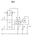
- FIG. 1 schematically shows an embodiment of a control device 1 of an AC motor for a not separately shown adjusting system.
- the adjusting system can in particular be formed by a roller shutter, an awning, a roller shutter, a blind, an interior roller blind or a screen.
- the adjusting system can be moved between an upper and lower end position.
- the AC motor is operated in two different directions.
- a switch is arranged, which is formed in the present case of a triac 5.
- a triac 5 In principle, a power transistor or the like can be used.
- a line 6, 7 is guided on one of the windings 2, 3 of the AC motor.
- a mains voltage in the form of an AC voltage is applied to one of the two lines 6, 7.
- FIG. 1 shown schematically by applying the mains voltage to the first line 6, a first direction of the AC motor is given, with which an upward movement of the control system is performed. Accordingly, a downward movement of the actuating system is generated in the voltage applied to the second line 7 mains voltage.
- the circuit modules are connected via a further resistor 15 and a zener diode 16 and a poled capacitor 17 in a symmetrical manner to the neutral conductor N, wherein the zener diode 16 is used to limit the voltage.
- the microcontroller 14 thus assumes a control and control function for the AC motor.
- the running direction of the AC motor is detected continuously.
- the phase difference between the voltages applied to the windings 2, 3 of the alternating-current motor is determined in the microcontroller 14.
- the phase of the mains voltage is the voltage at the winding 2 of the AC motor, which is connected directly to the line 6, impressed. This means that the voltage across the winding 2 is in phase with the mains voltage.
- phase shift is due to the fact that the winding module 3 associated circuit module forms a defined base load.
- the power supply capacitor 11 of the circuit module is the basic load essentially determining element.
- the phase of the voltage across the winding 3 is influenced such that it follows the phase of the winding 2 by a defined amount.
- the mains voltage is applied only to the line 7 of the control device 1 according to FIG. 1 connected.
- the signal state of the monitoring signal obtained thereby puts the control device 1 into a parameterization mode in which parameter values can generally be changed.
- position values of the AC motor in particular the end positions to be approached, are deleted.
- the deletion of the parameter values is preferably acknowledged with an acoustic signal.
- the running direction of the AC motor is continuously monitored. This can in particular be detected immediately when the user performs an external switching signal during the course of the AC motor direct switching, that is, the direction of the AC motor changes abruptly.
Landscapes
- Engineering & Computer Science (AREA)
- Structural Engineering (AREA)
- Power Engineering (AREA)
- Architecture (AREA)
- Civil Engineering (AREA)
- Control Of Ac Motors In General (AREA)
- Valve Device For Special Equipments (AREA)
- Massaging Devices (AREA)
- Iron Core Of Rotating Electric Machines (AREA)
- Stopping Of Electric Motors (AREA)
- Control Of Throttle Valves Provided In The Intake System Or In The Exhaust System (AREA)
- Operating, Guiding And Securing Of Roll- Type Closing Members (AREA)
Abstract
Description
Die Erfindung betrifft eine Steuereinrichtung gemäß dem Oberbegriff des Anspruchs 1.The invention relates to a control device according to the preamble of
Eine derartige Steuereinrichtung ist aus der
Mit dieser Steuereinrichtung soll ein sicheres Abschalten an den Endpositionen des AC-Jalousiemotors ohne zusätzliche mechanische Endschalter gewährleistet werden. Weiterhin darf der AC-Jalousiemotor nicht in Auf-Richtung gestartet werden, wenn er sich bereits in der oberen Endposition befindet. Dasselbe gilt sinngemäß für den in der unteren Endposition befindlichen AC-Jalousiemotor. In diesem Fall darf dieser nicht gestartet werden, wenn die Wechselspannung an der Leitung für die Abwärtsbewegung anliegt.This control device is to ensure a safe shutdown at the end positions of the AC blind motor without additional mechanical limit switch. Furthermore, the AC blind motor must not be started in the up direction when it is already in the upper end position. The same applies mutatis mutandis to the located in the lower end position AC blind motor. In this case, it must not be started when the AC voltage is applied to the line for the downward movement.
Der AC-Jalousiemotor dreht sich erst dann in Auf- oder Abwärts-Richtung, wenn der Schalter bildende Triac dauerhaft gezündet wird.The AC blind motor does not turn up or down until the switch forming triac is permanently ignited.
Zur Drehrichtungserkennung des AC-Jalousiemotors ist es wichtig zu erkennen, an welche der Leitungen die Wechselspannung angeschlossen wurde.To detect the direction of rotation of the AC blind motor, it is important to recognize to which of the lines the AC voltage was connected.
In Ruhestand des AC- Jalousie motors liegt die Wechselspannung am einer der beiden Leitugen, jedoch ist der Triac nicht gezündet. Da die Wicklungen des AC-Jalousiemotors über den Motorkondensator gekoppelt sind, liegt die Wechselspannung phasengleich an beiden Wicklungen.When the AC blind motor is retired, the AC voltage is applied to one of the two ducts, but the triac is not ignited. Since the windings of the AC blind motor are coupled via the motor capacitor, the alternating voltage is in phase on both windings.
Die Drehrichtungserkennung des AC-Jalousiemotors im Ruhezustand erfolgt bei an einer der Leitungen anliegenden Wechselspannung derart, dass der Triac nur kurzzeitig gezündet wird. Damit geht ein kurzer energiearmer Impuls zum Motor, der noch nicht zur Erzeugung einer Drehbewegung ausreicht. Jedoch wird durch diesen Impuls kurzzeitig eine Phasendifferenz der Spannungen an den beiden Wicklungen induziert. Aus dieser Phasendifferenz kann die Drehrichtung des AC-Jalousiemotors ermittelt werden.The direction of rotation detection of the AC blind motor in the idle state is carried out when applied to one of the lines AC voltage such that the triac is ignited only briefly. This is a short low-energy impulse to the engine, which is not enough to generate a rotary motion. However, this pulse temporarily induces a phase difference of the voltages across the two windings. From this phase difference, the direction of rotation of the AC blind motor can be determined.
Nachteilig hierbei ist, dass zur Drehrichtungserkennung der Triac kurzzeitig gezündet werden muss, wobei die Zeit, über welche der Triac gezündet ist, exakt vorgegeben werden muss, damit dieser nicht zu einem Einschalten des AC-Jalousiemotors führt. Dies bedingt einen unerwünschten Schaltungsaufwand für die Drehrichtungserkennung.The disadvantage here is that the direction of rotation of the triac must be ignited briefly, the time over which the triac is ignited, must be specified exactly so that it does not lead to a switching on the AC blind motor. This requires an undesirable circuit complexity for the direction of rotation detection.
Weiterhin ist nachteilig, dass mit dieser Steuereinrichtung nur kurzzeitig während des Ruhezustands des AC-Jalousiemotors eine Drehrichtungserkennung durchführbar ist.A further disadvantage is that with this control device only a short time during the idle state of the AC blind motor, a direction of rotation detection is feasible.
Aus der
Der Erfindung liegt die Aufgabe zugrunde, eine Steuereinrichtung der eingangs genannten Art so auszubilden, dass mit dieser eine zuverlässige, fortlaufende Drehrichtungserkennung eines Wechselstrommotors durchführbar ist.The invention has the object of providing a control device of the type mentioned in such a way that with this a reliable, continuous direction of rotation detection of an AC motor is feasible.
Zur Lösung dieser Aufgabe sind die Merkmale des Anspruchs 1 vorgesehen. Vorteilhafte Ausführungsformen und zweckmäßige Weiterbildungen der Erfindung sind in den Unteransprüchen beschrieben.To solve this problem, the features of
Die erfindungsgemäße Steuereinrichtung eines in zwei Laufrichtungen betreibbaren Wechselstrommotors für ein Stellsystem weist einen Schalter zum Ein-oder Ausschalten des Wechselstrommotors auf. Eine Laufrichtung ist vorgebbar, indem eine Netzspannung entweder eine an eine erste oder eine zweite Wicklung des Wechselstrommotors angelegt wird. Jeder Wicklung ist ein Schaltungsmodul mit einer vorgegebenen Grundlast zugeordnet. Die Spannung an einer ersten Wicklung, an der die Netzspannung anliegt, ist phasengleich zu dieser Netzspannung. Der Spannung an der zweiten Wicklung ist eine von dem Schaltungsmodul abhängige Phasendifferenz bezüglich der Spannung an der ersten Wicklung aufgeprägt, falls an die zweite Wicklung die Netzspannung nicht angelegt ist. In einer Auswerteeinheit wird aus der Phasendifferenz der Spannungen an beiden Wicklungen die Laufrichtung des Wechselstrommotors ermittelt.The inventive control device of an operable in two directions AC motor for a control system has a switch for switching on or off of the AC motor. A running direction can be predetermined by applying a mains voltage either to a first or a second winding of the AC motor. Each winding is associated with a circuit module with a given base load. The voltage at a first winding, to which the mains voltage is applied, is in phase with this mains voltage. The voltage at the second winding is impressed by a phase difference dependent on the circuit module with respect to the voltage at the first winding, if the mains voltage is not applied to the second winding. In an evaluation unit, the running direction of the AC motor is determined from the phase difference of the voltages at both windings.
Der Grundgedanke der Erfindung besteht darin, dass durch die den Wicklungen zugeordneten Schaltungsmodulen bei Anlegen einer Netzspannung in Form einer Wechselspannung an eine der Wicklungen eine Phasendifferenz dieser Wechselspannung zu der Spannung an der zweiten Wicklung entsteht, anhand derer die Laufrichtung des Wechselstrommotors fortlaufend ermittelbar ist.The basic idea of the invention is that, when a mains voltage in the form of an alternating voltage is applied to one of the windings, the circuit modules assigned to the windings produce a phase difference of this alternating voltage relative to the voltage at the second winding, with the aid of which the direction of rotation of the alternating current motor can be continuously determined.
Die Schaltungsmodule weisen dabei vorzugsweise jeweils ein kapazitives Schaltungselement auf, durch welches die Phasenverschiebung bewirkt wird. In einer besonders einfachen und kostengünstigen Ausführungsform besteht jedes Schaltungsmodul aus einem Netzteilkondensator sowie wenigstens einem Widerstand.The circuit modules preferably each have a capacitive circuit element, by which the phase shift is effected. In a particularly simple and inexpensive embodiment, each circuit module consists of a power supply capacitor and at least one resistor.
Bei Anlegen der Netzspannung an eine der Wicklungen wird die Phase der Netzspannung der Spannung an dieser Wicklung aufgeprägt. Durch die Grundlast des Schaltungsmoduls an der anderen Wicklung ist die Spannung an dieser Wicklung jedoch gegenüber der Netzspannung phasenverschoben.When the mains voltage is applied to one of the windings, the phase of the mains voltage is impressed on the voltage at this winding. However, due to the base load of the circuit module on the other winding, the voltage across this winding is out of phase with the line voltage.
Ein wesentlicher Vorteil der Erfindung besteht darin, dass bei an einer Wicklung angelegten Netzspannung fortdauernd eine Phasendifferenz der Spannungen an den beiden Wicklungen erhalten wird, und zwar unabhängig davon, ob der den Schalter bildende Triac gezündet ist oder nicht.A significant advantage of the invention is that when applied to a winding mains voltage continuously a phase difference of the voltages is obtained at the two windings, regardless of whether the triac forming the switch is ignited or not.
Damit wird eine fortlaufende, reproduzierbare Bestimmung der Laufrichtung des Wechselstrommotors ermöglicht. Insbesondere ist eine Laufrichtungsbestimmung sowohl im Ruhezustand des Wechselstrommotors, das heißt bei nicht gezündetem Triac, als auch während des Laufs des Wechselstrommotors möglich.This allows a continuous, reproducible determination of the direction of the AC motor. In particular, a direction determination is possible both in the resting state of the AC motor, that is, when the triac is not ignited, as well as during the running of the AC motor.
Weiterhin kann mit der erfindungsgemäßen Steuereinrichtung auch der Zustand erfasst werden, in welchem beide Wicklungen an die Netzspannung angeschlossen sind. In diesem Fall sind die Spannungen an den Wicklungen des Wechselstrommotors phasengleich. In dieser Beschaltung können beispielsweise Parameterwerte des Wechselstrommotors geändert oder insbesondere gelöscht werden. Durch die in der Auswerteeinheit durchgeführte Analyse des Vorzeichens der Phasendifferenz kann dieser Zustand von den beiden unterschiedlichen Laufrichtungen des Wechselstrommotors eindeutig unterschieden werden.Furthermore, the state in which both windings are connected to the mains voltage can also be detected with the control device according to the invention. In this case, the voltages on the windings of the AC motor are in phase. In this circuit, for example, parameter values of the AC motor can be changed or, in particular, deleted. By carrying out in the evaluation unit analysis of the sign of the phase difference, this state can be clearly distinguished from the two different directions of the AC motor.
Die erfindungsgemäße Steuereinrichtung kann generell für Stellsysteme wie zum Beispiel Rollläden, Markisen, Rolltore, Jalousien, Innenrollos oder Screens eingesetzt werden.The control device according to the invention can generally be used for positioning systems such as roller shutters, awnings, roller shutters, blinds, interior blinds or screens.
Mit der erfindungsgemäßen Steuereinrichtung kann im Ruhezustand des Wechselstrommotors, das heißt bei noch stillstehendem Stellsystem die Laufrichtung des Wechselstrommotors erfasst werden.With the control device according to the invention, the running direction of the AC motor can be detected in the idle state of the AC motor, that is, when still stationary adjusting system.
Weiterhin kann mit der erfindungsgemäßen Steuereinrichtung auch eine vom Benutzer während des Laufs des Stellsystems vorgenommene Laufrichtungsumschaltung des Stellsystems sofort erkannt und gemeldet werden. Zweckmäßigerweise wird in der Auswerteeinheit bei einer derartigen Direktumschaltung das Stellsystem zunächst gestoppt, so dass dann der Benutzer mit einem weiteren Eingabebefehl das Stellsystem neu startet. Dadurch wird ein kontrollierter Neuanlauf des Stellsystems, aus welchem heraus die jeweilige Endposition sicher angefahren werden kann, gewährleistet.Furthermore, with the control device according to the invention also made by the user during the course of the control system running direction switching of the control system are recognized and reported immediately. Appropriately, in the evaluation in such a direct switching, the control system is initially stopped, so that then the user restarts the control system with a further input command. This ensures a controlled restart of the positioning system, from which the respective end position can be approached safely.
Die Erfindung wird im Nachstehenden anhand der Zeichnungen erläutert. Es zeigen:
- Figur 1:
- Schematische Darstellung einer Steuereinrichtung eines Wechselstrommotors für ein Stellsystem.
- Figur 2:
- Phasenverlauf der Spannungen an den Wicklungen des Wechselstrommotors für eine erste Laufrichtung des Wechselstrommotors.
- Figur 3:
- Phasenverlauf der Spannungen an den Wicklungen des Wechselstrommotors für eine zweite Laufrichtung des Wechselstrommotors.
- Figur 4:
- Phasenverlauf der Spannungen an den Wicklungen des Wechselstrommotors bei gleichzeitig an beiden Wicklungen anliegender Netzspannung.
- FIG. 1:
- Schematic representation of a control device of an AC motor for a control system.
- FIG. 2:
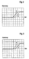
- Phase characteristic of the voltages on the windings of the AC motor for a first direction of the AC motor.
- FIG. 3:
- Phase characteristic of the voltages on the windings of the AC motor for a second direction of the AC motor.
- FIG. 4:
- Phase characteristic of the voltages on the windings of the AC motor with simultaneously applied to both windings mains voltage.
Generell kann das Stellsystem zwischen einer oberen und unteren Endposition verfahren werden. Zur Durchführung der Aufwärts- und Abwärtsbewegung des Stellsystems wird der Wechselstrommotor in zwei unterschiedlichen Laufrichtungen betrieben.In general, the adjusting system can be moved between an upper and lower end position. To perform the upward and downward movement of Stellstell the AC motor is operated in two different directions.
Wie aus
Zwischen den Wicklungen 2, 3 des Wechselstrommotors und einem Nullleiter N ist ein Schalter angeordnet, der im vorliegenden Fall von einem Triac 5 gebildet ist. Anstelle eines Triacs 5 ist prinzipiell auch ein Leistungstransistor oder dergleichen einsetzbar.Between the
Jeweils eine Leitung 6, 7 ist auf eine der Wicklungen 2, 3 des Wechselstrommotors geführt. Zur Vorgabe der Laufrichtung des Wechselstrommotors wird an eine der beiden Leitungen 6, 7 eine Netzspannung in Form einer Wechselspannung angelegt. Wie in
Bei abgetrenntem Nullleiter N ist der Triac 5 nicht gezündet, so dass sich der Wechselstrommotor im Ruhezustand befindet. Wird der Triac 5 gezündet, so dreht sich der Wechselstrommotor in der Laufrichtung, die durch das Anlegen der Netzspannung an eine der Leitungen 6, 7 vorgegeben ist.When disconnected neutral N of the
Jeder Wicklung 2, 3 des Wechselstrommotors ist ein Schaltungsmodul zugeordnet. Die Schaltungsmodule weisen einen identischen Aufbau auf. Das erste Schaltungsmodul, welches an die erste Wicklung 2 angeschlossen ist, besteht aus einem Netzteilkondensator 8 und zwei in Reihe geschalteten Widerständen 9, 10. Entsprechend weist auch das zweite Schaltungsmodul einen Netzteilkondensator 11 und zwei in Reihe geschaltete Widerstände 12, 13 auf.Each winding 2, 3 of the AC motor is associated with a circuit module. The circuit modules have an identical structure. The first circuit module, which is connected to the first winding 2, consists of a
Die Wicklungen 2, 3 und die zugeordneten Schaltungsmodule bilden zwei symmetrische Schaltungszweige, an welche der Triac 5 sowie eine Auswerteeinheit angeschlossen sind. Die Auswerteeinheit besteht im vorliegenden Fall aus einem Microcontroller 14. Jeweils von einem Widerstand 10, 13 eines Schaltungsmoduls ist eine Zuleitung auf jeweils einen Eingang des Microcontrollers 14 geführt.The
Die Schaltungsmodule sind über einen weiteren Widerstand 15 sowie eine Zenerdiode 16 und einen gepolten Kondensator 17 in symmetrischer Weise an den Nullleiter N angeschlossen, wobei die Zenerdiode 16 zur Spannungsbegrenzung dient.The circuit modules are connected via a
In dem Microcontroller 14 sind Parameterwerte zur Steuerung des Wechselstrommotors und damit des Stellsystems gespeichert. Hierzu gehören insbesondere Positionswerte wie die obere und untere Endposition des Stellsystems.In the
Der Microcontroller 14 übernimmt somit eine Kontroll- und Steuerfunktion für den Wechselstrommotor. Insbesondere wird in dem Microcontroller 14 die Laufrichtung des Wechselstrommotors fortlaufend erfasst.The
Zur Ermittlung der Laufrichtung wird in dem Microcontroller 14 die Phasendifferenz der an den Wicklungen 2, 3 des Wechselstrommotors anliegenden Spannungen bestimmt.In order to determine the direction of travel, the phase difference between the voltages applied to the
Zur Durchführung einer Aufwärtsbewegung des Stellsystems wird die Netzspannung nur an die Leitung 6 der Steuereinrichtung 1 gemäß
Die Phase der Netzspannung wird der Spannung an der Wicklung 2 des Wechselstrommotors, welche an die Leitung 6 unmittelbar angeschlossen ist, aufgeprägt. Dies bedeutet, dass die Spannung an der Wicklung 2 phasengleich mit der Netzspannung ist.The phase of the mains voltage is the voltage at the winding 2 of the AC motor, which is connected directly to the
Obwohl die zweite Wicklung 3 des Wechselstrommotors über den Motorkondensator 4 an die erste Wicklung 2 gekoppelt ist, ist die Spannung an der Wicklung 3 bezüglich der Spannung an der Wicklung 2 phasenverschoben.Although the second winding 3 of the AC motor is coupled to the first winding 2 via the motor capacitor 4, the voltage across the winding 3 is out of phase with respect to the voltage across the winding 2.
Diese Phasenverschiebung ist dadurch bedingt, dass das der Wicklung 3 zugeordnete Schaltungsmodul eine definierte Grundlast bildet. Im vorliegenden Fall ist der Netzteilkondensator 11 des Schaltungsmoduls das die Grundlast im Wesentlichen bestimmende Element. Durch dieses kapazitive Element wird die Phase der Spannung an der Wicklung 3 derart beeinflusst, dass diese der Phase an der Wicklung 2 um einen definierten Betrag nachläuft.This phase shift is due to the fact that the winding
Der Phasenverlauf der Spannungen an den Wicklungen 2 und 3 bei allein an der Leitung 6 anliegender Netzspannung ist in
Zur Durchführung einer Abwärtsbewegung des Schließsystems 1 wird die Netzspannung nur an die Leitung 7 der Steuereinrichtung 1 gemäß
In diesem Fall wird die Phase der Netzspannung der Spannung an der Wicklung 3 aufgeprägt, so dass diese phasengleich mit der Netzspannung ist.In this case, the phase of the mains voltage of the voltage is impressed on the winding 3, so that it is in phase with the mains voltage.
Demgegenüber ist die Spannung an der Wicklung 2 gegenüber der Netzspannung und damit gegenüber der Spannung an der Wicklung 3 phasenverschoben.In contrast, the voltage across the winding 2 with respect to the mains voltage and thus with respect to the voltage on the winding 3 is phase-shifted.
Diese Phasenverschiebung wird durch das der Wicklung 2 zugeordnete Schaltungsmodul, insbesondere durch den Netzteilkondensator 8 des Schaltungsmoduls bewirkt.This phase shift is caused by the winding module 2 associated circuit module, in particular by the
Der Phasenverlauf der Spannungen an den Wicklungen 2 und 3 bei allein an der Leitung 7 anliegender Netzspannung ist in
Da die Schaltungsmodule, welche den beiden Wicklungen 2 und 3 zugeordnet sind, identisch ausgebildet sind, sind die Beträge der Phasenverschiebungen der Spannungen an den Wicklungen 2 und 3 für die in den
In dem Microcontroller 14 erfolgt eine Generierung eines Überwachungssignals, indem das Vorzeichen der Phasenverschiebungen der Signale A und B ausgewertet wird.In the
Je nach Vorzeichen der Phasenverschiebung signalisieren zwei Signalzustände des Überwachungssignals die unterschiedlichen Laufrichtungen des Wechselstrommotors. Für den in
Schließlich kann das Überwachungssignal einen dritten Signalzustand einnehmen, der dem Wert Null der Phasenverschiebung zwischen den Spannungen an beiden Wicklungen 2, 3 entspricht.Finally, the monitoring signal can assume a third signal state, which corresponds to the value zero of the phase shift between the voltages at both
Dieser Signalzustand wird dann erhalten, wenn gleichzeitig an beide Leitungen 6, 7 die Netzspannung angelegt wird. In diesem Fall wird den Spannungen an beiden Wicklungen 2, 3 die Phase der Netzspannung aufgeprägt, so dass diese gleichphasig sind.This signal state is obtained when the mains voltage is simultaneously applied to both
Der dabei erhaltene Signalzustand des Überwachungssignals versetzt die Steuereinrichtung 1 in einen Parametriermodus, in dem allgemein Parameterwerte geändert werden können. Im vorliegenden Fall werden Positionswerte des Wechselstrommotors, insbesondere die anzufahrenden Endpositionen, gelöscht. Das Löschen der Parameterwerte wird vorzugsweise mit einem akustischen Signal quittiert.The signal state of the monitoring signal obtained thereby puts the
Die Bestimmung der Phasendifferenz der Spannungen an den beiden Wicklungen 2, 3 und damit die Generierung der Signalzustände des Überwachungssignals erfolgt kontinuierlich fortlaufend. Dabei erfolgt die Bestimmung der Phasendifferenzen insbesondere auch unabhängig davon, ob der Triac 5 gezündet ist oder nicht.The determination of the phase difference of the voltages at the two
Somit kann einerseits vor Anlauf des Wechselstrommotors, das heißt vor Zünden des Tricas die Phasendifferenz und damit die durch Anlegen der Netzspannung an eine der Leitungen 6 oder 7 vorgegebene Laufrichtung des Wechselstrommotors ermittelt werden.Thus, on the one hand before starting the AC motor, that is, before the ignition of the Trica, the phase difference and thus determined by applying the mains voltage to one of the
Andererseits wird auch während des Laufs des Wechselstrommotors die Laufrichtung des Wechselstrommotors fortlaufend überwacht. Damit kann insbesondere unmittelbar festgestellt werden, wenn der Benutzer durch eine externe Signaleingabe während des Laufs des Wechselstrommotors eine Direktumschaltung vornimmt, das heißt die Laufrichtung des Wechselstrommotors abrupt ändert.On the other hand, even during the running of the AC motor, the running direction of the AC motor is continuously monitored. This can in particular be detected immediately when the user performs an external switching signal during the course of the AC motor direct switching, that is, the direction of the AC motor changes abruptly.
Durch die fortlaufende Messung der Phasendifferenz der Spannungen an den Wicklungen 2 und 3 wird diese Direktumschaltung unmittelbar im Microcontroller 14 erfasst, so dass über diesen geeignete Maßnahmen eingeleitet werden. Vorzugsweise wird bei einer derartigen Direktumschaltung der Wechselstrommotor zunächst gestoppt, worauf der Benutzer mit einer zweiten Signaleingabe einen Neustart vornehmen kann. Durch diesen kontrollierten Neustart wird dann gewährleistet, dass der Wechselstrommotor entsprechend der vorgegebenen Laufrichtung des Wechselstrommotors in seine Endposition läuft.Due to the continuous measurement of the phase difference of the voltages on the
- (1)(1)
- Steuereinrichtungcontrol device
- (2)(2)
- Wicklungwinding
- (3)(3)
- Wicklungwinding
- (4)(4)
- Motorkondensatormotor capacitor
- (5)(5)
- Triactriac
- (6)(6)
- Leitungmanagement
- (7)(7)
- Leitungmanagement
- (8)(8th)
- NetzteilkondensatorPower supply capacitor
- (9)(9)
- Widerstandresistance
- (10)(10)
- Widerstandresistance
- (11)(11)
- NetzteilkondensatorPower supply capacitor
- (12)(12)
- Widerstandresistance
- (13)(13)
- Widerstandresistance
- (14)(14)
- Microcontrollermicrocontrollers
- (15)(15)
- Widerstandresistance
- (16)(16)
- ZenerdiodeZener diode
- (17)(17)
- Kondensatorcapacitor
- AA
- Spannung an Wicklung 2Voltage on winding 2
- BB
- Spannung an Wicklung 3Voltage on winding 3
- NN
- Nullleiterneutral
Claims (15)
- Control device of an alternating current motor, which is operable in two directions of running, for a setting system, with a switch for switching the alternating current motor on and off, wherein a direction of running is predeterminable in that a mains voltage is applied to either a first or a second winding of the alternating current motor, characterised in that a switching module with a predetermined base load is associated with each winding (2, 3), wherein the voltage at a first winding (2) to which the mains voltage is applied has the same phase as this mains voltage and wherein a phase difference, which is dependent on the switching module, with respect to the voltage at the first winding (2) is imposed on the voltage at the second winding (3) if the mains voltage is multiplied to the second winding (3) and the direction of running of the alternating current motor is determined in an evaluating unit from this phase difference of the voltages at the two windings (2, 3) regardless of whether or not the switch is triggered.
- Control device according to claim 1, characterised in that the two windings (2, 3) of the alternating current motor are of identical construction.
- Control device according to claim 1 or 2, characterised in that the switching modules associated with the windings (2, 3) are identical.
- Control device according to one of claims 1 to 3, characterised in that each switching module has a mains power supply capacitor (8, 11).
- Control device according to claim 4, characterised in that each switching module has at least one resistor (9 to 13) associated with the mains power supply capacitor (8, 11).
- Control device according to one of claims 1 to 5, characterised in that the windings (2, 3) form together with the switching modules two symmetrical switching branches with which the evaluating unit and the switch are connected.
- Control device according to claim 6, characterised in that each switching branch has a line (6, 7) for connection with the mains voltage.
- Control device according to one of claims 1 to 7, characterised in that the switch is formed by a triac (5).
- Control device according to one of claims 1 to 8, characterised in that the evaluating unit is formed by a microcontroller (14).
- Control device according to claim 9, characterised in that a feed line is led from each resistor (10, 13) of a switching module to an input of the microcontroller (14).
- Control device according to one of claims 1 to 10, characterised in that the mains voltage can be simultaneously applied to both windings (2, 3) of the alternating current motor so that the voltages at the windings (2, 3) are of the same phase.
- Control device according to claim 11, characterised in that when the mains voltage is applied simultaneously to the windings (2, 3) parameter values of the alternating current motor can be changed.
- Control device according to claim 12, characterised in that when mains voltage is applied simultaneously to the windings (2, 3) parameter values of the alternating current motor are erased.
- Control device according to one of claims 1 to 13, characterised in that different states of a monitoring signal are derived in the evaluating unit from the sign of the phase difference of the voltages at the two windings (2, 3).
- Control device according to one of claims 1 to 14, characterised in that the setting system is formed by a roller shutter, an awning, a roller door, a Venetian blind, an inside roller blind or a screen.
Priority Applications (1)
| Application Number | Priority Date | Filing Date | Title |
|---|---|---|---|
| PL04730503T PL1632017T3 (en) | 2003-06-06 | 2004-04-30 | Control device |
Applications Claiming Priority (2)
| Application Number | Priority Date | Filing Date | Title |
|---|---|---|---|
| DE20308840U DE20308840U1 (en) | 2003-06-06 | 2003-06-06 | control device |
| PCT/EP2004/004582 WO2004109903A1 (en) | 2003-06-06 | 2004-04-30 | Control device |
Publications (2)
| Publication Number | Publication Date |
|---|---|
| EP1632017A1 EP1632017A1 (en) | 2006-03-08 |
| EP1632017B1 true EP1632017B1 (en) | 2008-03-26 |
Family
ID=27771737
Family Applications (1)
| Application Number | Title | Priority Date | Filing Date |
|---|---|---|---|
| EP04730503A Expired - Lifetime EP1632017B1 (en) | 2003-06-06 | 2004-04-30 | Control device |
Country Status (8)
| Country | Link |
|---|---|
| EP (1) | EP1632017B1 (en) |
| AT (1) | ATE390753T1 (en) |
| DE (2) | DE20308840U1 (en) |
| DK (1) | DK1632017T3 (en) |
| ES (1) | ES2301985T3 (en) |
| NO (1) | NO331609B1 (en) |
| PL (1) | PL1632017T3 (en) |
| WO (1) | WO2004109903A1 (en) |
Cited By (1)
| Publication number | Priority date | Publication date | Assignee | Title |
|---|---|---|---|---|
| WO2024127247A1 (en) * | 2022-12-15 | 2024-06-20 | Master S.P.A. | Drive and control unit for the motor-driven displacement of sheets for pergolas and relative operation |
Families Citing this family (4)
| Publication number | Priority date | Publication date | Assignee | Title |
|---|---|---|---|---|
| DE10357312B4 (en) | 2003-12-09 | 2007-05-16 | Elero Gmbh Antriebstechnik | Device for operating a positioning system |
| FR2880216B1 (en) * | 2004-12-24 | 2007-04-20 | Deprat Jean Sa Sa | DEVICE AND METHOD FOR CONTROLLING AN ELECTRONIC LIMITER CAGE ENGINE |
| FR2886786B1 (en) * | 2005-06-01 | 2007-08-17 | Somfy Sas | ACTUATOR FOR MANEUVERING A SHUTTER AND METHOD FOR OPERATING SUCH ACTUATOR |
| DE102016125912B4 (en) | 2016-10-11 | 2023-11-02 | Dehn Se | Two-phase overvoltage protection arrangement for electric motor drives |
Family Cites Families (5)
| Publication number | Priority date | Publication date | Assignee | Title |
|---|---|---|---|---|
| US3993940A (en) * | 1974-12-26 | 1976-11-23 | Borg-Warner Corporation | Latching system for two-phase reversible motor |
| AU569646B2 (en) * | 1984-12-18 | 1988-02-11 | Toshiba, Kabushiki Kaisha | Detecting critical rotation speed of an induction motor |
| US4745347A (en) * | 1986-09-24 | 1988-05-17 | Pt Components, Inc. | Low cost instant reversing circuit |
| FR2717641B1 (en) * | 1994-03-16 | 1996-05-15 | Somfy | Device indicating the state of a single-phase asynchronous motor. |
| DE10044029B4 (en) | 2000-09-06 | 2014-03-20 | Beatrix Gross | Control arrangement of an AC Venetian blind motor or an AC tubular motor |
-
2003
- 2003-06-06 DE DE20308840U patent/DE20308840U1/en not_active Expired - Lifetime
-
2004
- 2004-04-30 AT AT04730503T patent/ATE390753T1/en active
- 2004-04-30 EP EP04730503A patent/EP1632017B1/en not_active Expired - Lifetime
- 2004-04-30 ES ES04730503T patent/ES2301985T3/en not_active Expired - Lifetime
- 2004-04-30 DE DE502004006673T patent/DE502004006673D1/en not_active Expired - Lifetime
- 2004-04-30 PL PL04730503T patent/PL1632017T3/en unknown
- 2004-04-30 WO PCT/EP2004/004582 patent/WO2004109903A1/en not_active Ceased
- 2004-04-30 DK DK04730503T patent/DK1632017T3/en active
-
2005
- 2005-12-23 NO NO20056150A patent/NO331609B1/en not_active IP Right Cessation
Cited By (1)
| Publication number | Priority date | Publication date | Assignee | Title |
|---|---|---|---|---|
| WO2024127247A1 (en) * | 2022-12-15 | 2024-06-20 | Master S.P.A. | Drive and control unit for the motor-driven displacement of sheets for pergolas and relative operation |
Also Published As
| Publication number | Publication date |
|---|---|
| PL1632017T3 (en) | 2008-11-28 |
| NO331609B1 (en) | 2012-02-06 |
| WO2004109903A8 (en) | 2005-03-17 |
| DK1632017T3 (en) | 2008-07-14 |
| NO20056150L (en) | 2005-12-23 |
| DE20308840U1 (en) | 2003-08-21 |
| ES2301985T3 (en) | 2008-07-01 |
| DE502004006673D1 (en) | 2008-05-08 |
| EP1632017A1 (en) | 2006-03-08 |
| ATE390753T1 (en) | 2008-04-15 |
| WO2004109903A1 (en) | 2004-12-16 |
Similar Documents
| Publication | Publication Date | Title |
|---|---|---|
| DE602005002889T2 (en) | A method of operating a shutter controlled and powered from a wire interface | |
| DE4123828C1 (en) | Contactless proximity switch for machine mounting - has standard connector for transmission of program data e.g. from EEPROM to set parameters of device | |
| DE2025743C3 (en) | Method and device for switching at least one alternating current consumer from one voltage or current source to another voltage or current source | |
| EP2409396B1 (en) | Correction of counting errors upon evaluation of current ripples in a dc motor | |
| EP1797634B1 (en) | Method and arrangement for controlling the electricity supply of an electronically commutated motor | |
| DE69914167T2 (en) | DEVICE FOR ACTUATING A TURN-OFF OR TURN-ON ELECTROMAGNET OF A CIRCUIT-BREAKER WITH LOCAL AND REMOTE CONTROL | |
| DE60017371T2 (en) | PROCESS AND DEVICE FOR PROGRAMMING A LOGIC UNIT BY SWITCHING | |
| EP2409397B1 (en) | Automatic detection of a mechanically commutated dc motor | |
| EP1490700A1 (en) | Circuit arrangement and method for testing an electric circuit | |
| DE102013218041A1 (en) | Method for operating an electric motor | |
| WO2004109903A1 (en) | Control device | |
| DE102018202784A1 (en) | Method for assigning operating parameters to local control units provided for controlling a door movement in a motor vehicle | |
| EP1186741A2 (en) | Control device of an AC motor for a blind or for a tubular AC motor | |
| EP0519089B1 (en) | Loading of operational parameters for a ready-for-use proximity switch | |
| DE10108975A1 (en) | Method for controlling an electric motor | |
| EP0650113A2 (en) | Method of paramatrisation of a digital voltage regulator, especially for controlling a transformer with a step switch | |
| DE60121499T2 (en) | Control for motorized dimming systems with perfected end stop | |
| EP1583214B1 (en) | Apparatus for operating a positioning system | |
| EP2564500B1 (en) | Switchless diac equivalent circuit | |
| DE3732214A1 (en) | IMMEDIATE SWITCHING SYSTEM FOR SINGLE-PHASE AC MOTOR | |
| DE2906937A1 (en) | CONTROL SYSTEM FOR THE CONTROL OF A DEVICE WITH A VARIETY OF MACHINE FUNCTIONS | |
| DE102021201359A1 (en) | SOFTSTART FOR ELECTRIC TOOLS WITH PUSH BUTTON SWITCH AND MECHANICAL DIRECTION SWITCH | |
| DE102020133519A1 (en) | CONTROL DEVICE FOR A ROTATING DEVICE, ROTATING DEVICE AND METHOD FOR CONTROLLING A ROTATING DEVICE | |
| DE10124877A1 (en) | Electronic stop detection for synchronous motors involves using change in switch-on duration and/or phase positions as criterion for detecting stop and switching off synchronous motor | |
| EP1215811B1 (en) | Method and device for monitoring stepper motors |
Legal Events
| Date | Code | Title | Description |
|---|---|---|---|
| PUAI | Public reference made under article 153(3) epc to a published international application that has entered the european phase |
Free format text: ORIGINAL CODE: 0009012 |
|
| 17P | Request for examination filed |
Effective date: 20051026 |
|
| AK | Designated contracting states |
Kind code of ref document: A1 Designated state(s): AT BE BG CH CY CZ DE DK EE ES FI FR GB GR HU IE IT LI LU MC NL PL PT RO SE SI SK TR |
|
| DAX | Request for extension of the european patent (deleted) | ||
| 17Q | First examination report despatched |
Effective date: 20070619 |
|
| GRAP | Despatch of communication of intention to grant a patent |
Free format text: ORIGINAL CODE: EPIDOSNIGR1 |
|
| GRAS | Grant fee paid |
Free format text: ORIGINAL CODE: EPIDOSNIGR3 |
|
| GRAA | (expected) grant |
Free format text: ORIGINAL CODE: 0009210 |
|
| RBV | Designated contracting states (corrected) |
Designated state(s): AT BE CH DE DK ES FI FR GB HU IT LI PL SE |
|
| AK | Designated contracting states |
Kind code of ref document: B1 Designated state(s): AT BE CH DE DK ES FI FR GB HU IT LI PL SE |
|
| REG | Reference to a national code |
Ref country code: GB Ref legal event code: FG4D Free format text: NOT ENGLISH |
|
| REG | Reference to a national code |
Ref country code: CH Ref legal event code: EP Ref country code: CH Ref legal event code: NV Representative=s name: ROTTMANN, ZIMMERMANN + PARTNER AG |
|
| REF | Corresponds to: |
Ref document number: 502004006673 Country of ref document: DE Date of ref document: 20080508 Kind code of ref document: P |
|
| REG | Reference to a national code |
Ref country code: SE Ref legal event code: TRGR |
|
| REG | Reference to a national code |
Ref country code: ES Ref legal event code: FG2A Ref document number: 2301985 Country of ref document: ES Kind code of ref document: T3 |
|
| REG | Reference to a national code |
Ref country code: DK Ref legal event code: T3 |
|
| REG | Reference to a national code |
Ref country code: HU Ref legal event code: AG4A Ref document number: E003157 Country of ref document: HU |
|
| REG | Reference to a national code |
Ref country code: PL Ref legal event code: T3 |
|
| ET | Fr: translation filed | ||
| PLBE | No opposition filed within time limit |
Free format text: ORIGINAL CODE: 0009261 |
|
| STAA | Information on the status of an ep patent application or granted ep patent |
Free format text: STATUS: NO OPPOSITION FILED WITHIN TIME LIMIT |
|
| 26N | No opposition filed |
Effective date: 20081230 |
|
| REG | Reference to a national code |
Ref country code: CH Ref legal event code: PFA Owner name: ELERO GMBH Free format text: ELERO GMBH#LINSENHOFER STRASSE 59-63#72660 BEUREN (DE) -TRANSFER TO- ELERO GMBH#LINSENHOFER STRASSE 59-63#72660 BEUREN (DE) |
|
| PGFP | Annual fee paid to national office [announced via postgrant information from national office to epo] |
Ref country code: ES Payment date: 20120425 Year of fee payment: 9 |
|
| PGFP | Annual fee paid to national office [announced via postgrant information from national office to epo] |
Ref country code: AT Payment date: 20120411 Year of fee payment: 9 |
|
| PGFP | Annual fee paid to national office [announced via postgrant information from national office to epo] |
Ref country code: GB Payment date: 20130418 Year of fee payment: 10 Ref country code: DE Payment date: 20130405 Year of fee payment: 10 Ref country code: BE Payment date: 20130418 Year of fee payment: 10 Ref country code: SE Payment date: 20130418 Year of fee payment: 10 Ref country code: DK Payment date: 20130418 Year of fee payment: 10 Ref country code: CH Payment date: 20130422 Year of fee payment: 10 |
|
| PGFP | Annual fee paid to national office [announced via postgrant information from national office to epo] |
Ref country code: HU Payment date: 20130430 Year of fee payment: 10 Ref country code: FI Payment date: 20130411 Year of fee payment: 10 Ref country code: PL Payment date: 20130404 Year of fee payment: 10 Ref country code: FR Payment date: 20130515 Year of fee payment: 10 Ref country code: IT Payment date: 20130429 Year of fee payment: 10 |
|
| REG | Reference to a national code |
Ref country code: DE Ref legal event code: R119 Ref document number: 502004006673 Country of ref document: DE |
|
| REG | Reference to a national code |
Ref country code: DK Ref legal event code: EBP Effective date: 20140430 |
|
| REG | Reference to a national code |
Ref country code: CH Ref legal event code: PL |
|
| REG | Reference to a national code |
Ref country code: AT Ref legal event code: MM01 Ref document number: 390753 Country of ref document: AT Kind code of ref document: T Effective date: 20140430 |
|
| GBPC | Gb: european patent ceased through non-payment of renewal fee |
Effective date: 20140430 |
|
| REG | Reference to a national code |
Ref country code: FR Ref legal event code: ST Effective date: 20141231 |
|
| REG | Reference to a national code |
Ref country code: DE Ref legal event code: R119 Ref document number: 502004006673 Country of ref document: DE Effective date: 20141101 |
|
| PG25 | Lapsed in a contracting state [announced via postgrant information from national office to epo] |
Ref country code: CH Free format text: LAPSE BECAUSE OF NON-PAYMENT OF DUE FEES Effective date: 20140430 Ref country code: LI Free format text: LAPSE BECAUSE OF NON-PAYMENT OF DUE FEES Effective date: 20140430 Ref country code: FI Free format text: LAPSE BECAUSE OF NON-PAYMENT OF DUE FEES Effective date: 20140430 Ref country code: SE Free format text: LAPSE BECAUSE OF NON-PAYMENT OF DUE FEES Effective date: 20140501 Ref country code: DE Free format text: LAPSE BECAUSE OF NON-PAYMENT OF DUE FEES Effective date: 20141101 Ref country code: GB Free format text: LAPSE BECAUSE OF NON-PAYMENT OF DUE FEES Effective date: 20140430 |
|
| REG | Reference to a national code |
Ref country code: SE Ref legal event code: EUG |
|
| PG25 | Lapsed in a contracting state [announced via postgrant information from national office to epo] |
Ref country code: FR Free format text: LAPSE BECAUSE OF NON-PAYMENT OF DUE FEES Effective date: 20140430 Ref country code: HU Free format text: LAPSE BECAUSE OF NON-PAYMENT OF DUE FEES Effective date: 20140501 Ref country code: AT Free format text: LAPSE BECAUSE OF NON-PAYMENT OF DUE FEES Effective date: 20140430 |
|
| PG25 | Lapsed in a contracting state [announced via postgrant information from national office to epo] |
Ref country code: IT Free format text: LAPSE BECAUSE OF NON-PAYMENT OF DUE FEES Effective date: 20140430 |
|
| PG25 | Lapsed in a contracting state [announced via postgrant information from national office to epo] |
Ref country code: DK Free format text: LAPSE BECAUSE OF NON-PAYMENT OF DUE FEES Effective date: 20140430 |
|
| REG | Reference to a national code |
Ref country code: PL Ref legal event code: LAPE |
|
| PG25 | Lapsed in a contracting state [announced via postgrant information from national office to epo] |
Ref country code: PL Free format text: LAPSE BECAUSE OF NON-PAYMENT OF DUE FEES Effective date: 20140430 |
|
| REG | Reference to a national code |
Ref country code: ES Ref legal event code: FD2A Effective date: 20151204 |
|
| PG25 | Lapsed in a contracting state [announced via postgrant information from national office to epo] |
Ref country code: ES Free format text: LAPSE BECAUSE OF NON-PAYMENT OF DUE FEES Effective date: 20140501 |
|
| PG25 | Lapsed in a contracting state [announced via postgrant information from national office to epo] |
Ref country code: BE Free format text: LAPSE BECAUSE OF NON-PAYMENT OF DUE FEES Effective date: 20140430 |
|
| P01 | Opt-out of the competence of the unified patent court (upc) registered |
Free format text: CASE NUMBER: UPC_APP_0011471_1632017/2025 Effective date: 20251029 |