EP1631213B1 - Stent positioning system - Google Patents
Stent positioning system Download PDFInfo
- Publication number
- EP1631213B1 EP1631213B1 EP04734483.3A EP04734483A EP1631213B1 EP 1631213 B1 EP1631213 B1 EP 1631213B1 EP 04734483 A EP04734483 A EP 04734483A EP 1631213 B1 EP1631213 B1 EP 1631213B1
- Authority
- EP
- European Patent Office
- Prior art keywords
- stent
- balloon
- blood vessel
- tube
- locator means
- Prior art date
- Legal status (The legal status is an assumption and is not a legal conclusion. Google has not performed a legal analysis and makes no representation as to the accuracy of the status listed.)
- Expired - Lifetime
Links
- 210000004204 blood vessel Anatomy 0.000 claims description 13
- 229920001971 elastomer Polymers 0.000 claims description 8
- 239000000806 elastomer Substances 0.000 claims description 8
- 230000004308 accommodation Effects 0.000 claims 3
- 238000009877 rendering Methods 0.000 claims 1
- 230000003902 lesion Effects 0.000 description 12
- 210000000709 aorta Anatomy 0.000 description 8
- 208000031481 Pathologic Constriction Diseases 0.000 description 6
- 208000037804 stenosis Diseases 0.000 description 6
- 238000000034 method Methods 0.000 description 5
- 210000001367 artery Anatomy 0.000 description 4
- 238000002513 implantation Methods 0.000 description 3
- 230000036262 stenosis Effects 0.000 description 3
- 208000007536 Thrombosis Diseases 0.000 description 2
- 208000014674 injury Diseases 0.000 description 2
- 230000008733 trauma Effects 0.000 description 2
- 208000027418 Wounds and injury Diseases 0.000 description 1
- 238000002399 angioplasty Methods 0.000 description 1
- 230000003143 atherosclerotic effect Effects 0.000 description 1
- 210000003445 biliary tract Anatomy 0.000 description 1
- 210000004351 coronary vessel Anatomy 0.000 description 1
- 230000004807 localization Effects 0.000 description 1
- 230000002093 peripheral effect Effects 0.000 description 1
- 230000002966 stenotic effect Effects 0.000 description 1
- 210000003462 vein Anatomy 0.000 description 1
Images

Classifications
-
- A—HUMAN NECESSITIES
- A61—MEDICAL OR VETERINARY SCIENCE; HYGIENE
- A61F—FILTERS IMPLANTABLE INTO BLOOD VESSELS; PROSTHESES; DEVICES PROVIDING PATENCY TO, OR PREVENTING COLLAPSING OF, TUBULAR STRUCTURES OF THE BODY, e.g. STENTS; ORTHOPAEDIC, NURSING OR CONTRACEPTIVE DEVICES; FOMENTATION; TREATMENT OR PROTECTION OF EYES OR EARS; BANDAGES, DRESSINGS OR ABSORBENT PADS; FIRST-AID KITS
- A61F2/00—Filters implantable into blood vessels; Prostheses, i.e. artificial substitutes or replacements for parts of the body; Appliances for connecting them with the body; Devices providing patency to, or preventing collapsing of, tubular structures of the body, e.g. stents
- A61F2/95—Instruments specially adapted for placement or removal of stents or stent-grafts
- A61F2/958—Inflatable balloons for placing stents or stent-grafts
-
- A—HUMAN NECESSITIES
- A61—MEDICAL OR VETERINARY SCIENCE; HYGIENE
- A61F—FILTERS IMPLANTABLE INTO BLOOD VESSELS; PROSTHESES; DEVICES PROVIDING PATENCY TO, OR PREVENTING COLLAPSING OF, TUBULAR STRUCTURES OF THE BODY, e.g. STENTS; ORTHOPAEDIC, NURSING OR CONTRACEPTIVE DEVICES; FOMENTATION; TREATMENT OR PROTECTION OF EYES OR EARS; BANDAGES, DRESSINGS OR ABSORBENT PADS; FIRST-AID KITS
- A61F2/00—Filters implantable into blood vessels; Prostheses, i.e. artificial substitutes or replacements for parts of the body; Appliances for connecting them with the body; Devices providing patency to, or preventing collapsing of, tubular structures of the body, e.g. stents
- A61F2/82—Devices providing patency to, or preventing collapsing of, tubular structures of the body, e.g. stents
- A61F2002/821—Ostial stents
Definitions
- the present invention relates to a stent positioning system, more specifically, to such a system for the treatment of aorto-ostial lesions.
- An ostial lesion is defined as one arising within 3 mm of the origin of a blood vessel.
- Aorto-ostial lesions are those which damage the ostium of the main blood vessels branching from the aorta.
- a serious difficulty in the implantation of a stent in an aorto-ostial location is the determination of the exact position where the stent is to be disposed. If the stent is placed too far inside the vessel, it misses the ostium and the tightest portion of the stenosis. Yet, if the stent is placed too proximally, it extends into the aorta and may be subject to trauma from the guiding catheter. The potentials of compromising the aortal lumen and increasing the dangers of stent thrombosis and re-stenosis, also exist.
- U.S. Patent Application 2002/0091434 A1 discloses an apparatus and method for positioning a stent, where the positional element is constituted by wire loops for frictional engagement with the walls to position the stent at the deployment site. Upon exiting the guiding catheter, the wire loops automatically expand and engage the artery walls.
- US Pat. No. 5,749,890 entitled "Method and system for stent placement in ostial lesions” discloses a stent delivery assembly and method for stent placement in an ostial lesion.
- the stent delivery system disclosed thereby comprises a break segment, which changes configuration to facilitate localization of the target ostium.
- WO9936015 entitled “Catheter and method of ostial stent placement” discloses a catheter with two balloons for placing a stent at the ostium or junction of a variety of bodily tissues, including the junction of any artery, and an aorta to afford improved treatment of stenotic lesions.
- WO 03/105695 discloses a stent comprising an expandable cylindrical section and a flaring section attached thereto at a plurality of fingers, wherein the fingers couple radial expansion of the cylindrical section with flaring of the flaring section.
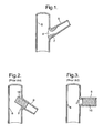
- Fig. 1 a typical ostial lesion, defined as a lesion arising within 3 mm of the origin of the blood vessel. More specifically, Fig. 1 illustrates an aorto-ostial atherosclerotic lesion, that produces a significant stenosis 2 at the ostium 4 of a coronary artery 6, where the artery branches off the aorta 8.
- Figs. 2 and 3 illustrate faulty prior art stent-to-vessel apposition.
- stent 10 is implanted in too proximal a location and is seen to project into aorta 8, where it is subject to trauma from the guiding catheter and is also liable to compromise the lumen of the aorta, increasing the danger of stent thrombosis and re-stenosis.
- Fig. 3 the stent is placed in too distal a location, missing the ostium 2 and the tightest portion of the stenosis.
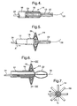
- the above-mentioned mishaps are avoided by the use of the stent positioning system of the present invention, a preferred embodiment of which is shown in Figs. 4 to 7 .
- the system is seen to consist of a guide tube 12, a locator 14, a sleeve having a first portion constituting an actuator 16, and a second portion 18 made of an elastomer. Portion 18 is provided with slots 20 extending in the longitudinal direction of the sleeve 18, possibly around its entire periphery.
- the system further includes a stent-expansion balloon 22 attached to the guide tube 12 and an inflation tube 24 through which balloon 22 can be inflated in order to expand the stent 10, indicated by dash-dotted lines in Fig. 4 .
- a thin special wire 26 passing through the system for the purpose per-se known.
- the actuator 16 When the actuator 16 is pushed in the direction of arrow A ( Fig. 5 ), the elastomer portion 18 of the sleeve will buckle and assume a substantially disk-like shape while forming a locator 14 having a plurality of fingers 28 in a star-like configuration ( Fig. 7 ).
- the balloon 22 Once the balloon 22 is accurately positioned in place by means of the locator 14, it is inflated (see Fig. 6 ), thereby expanding the stent 10.
- the remaining procedure is self-evident by men skilled in the art.
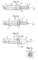
- the stent locator is in the form of a two-portion sleeve 30 made of an elastomer, which portions are advantageously separated by a weakened cross-section 31.
- the expansion balloon side of sleeve 30 is fixedly attached to the guide tube 12 and the other end of the sleeve 30 is attached to an actuator 32 in the form of a tube.
- actuator 32 When actuator 32 is pushed relative to guide tube 12 in the direction of arrow A, the elastomer sleeve 30 will buckle about its weakened cross-section 31, and assume a substantially disk-like shape, adapted to act as a stent locator 14 ( Fig. 9 ).
- the balloon 22 can be inflated ( Fig. 10 ) to expand the stent.
- a stent locator 14 in the form of a piece of wire 34, shown in Fig. 11 in its collapsed state.
- the piece of wire 34 is substantially U-shaped in its state of rest.
- the web of this U-shape passes through lateral holes 36 in the guide tube 12 and the two legs of the U are fixedly attached to the actuator 38 surrounding guide tube 12.
- actuator 38 When actuator 38 is pushed relative to guide tube 12 in the direction of arrow A ( Fig. 12 ), the U-shaped wire 34 is elastically deformed, as shown in Figs. 12 to 14 , increasing the length of the web, which can now act as a stent locator 14.
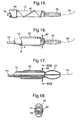
- FIG. 15 to 18 A further embodiment is illustrated in Figs. 15 to 18 .
- the sleeve 18 of Fig. 4 and sleeve 30 of Fig. 8 is replaced by a spring element 40 wound about the guide tube 12.
- the ends of the spring element 40 respectively, abut against, or are attached to, an actuator 42 and the end of the guide tube 12 close to the expansion balloon 22.
- the spring element 40 Upon sliding the actuator 42 in the direction of arrow A towards the expansion balloon 22 ( Fig. 16 ), the spring element 40 is compressed and forms loops ( Fig. 18 ), extending laterally from the axis of the expansion balloon 20 and stent (not shown) positioned thereon, so as to constitute an abutment for accurately locating the expandable stent mounted on the expansion balloon 22.
- the described stent positioning systems may be used for accurate stent implantation in any and all possible stenting locations, e.g., the aorta and all possible small or large branches arising from the aorta (coronary, carotid, subclavian, mesenteric, renal, iliac and other arteries), central and peripheral vein system (porto-caval stent etc.), biliary system, and tracheal location.
Landscapes
- Health & Medical Sciences (AREA)
- Engineering & Computer Science (AREA)
- Biomedical Technology (AREA)
- Cardiology (AREA)
- Oral & Maxillofacial Surgery (AREA)
- Transplantation (AREA)
- Heart & Thoracic Surgery (AREA)
- Vascular Medicine (AREA)
- Life Sciences & Earth Sciences (AREA)
- Animal Behavior & Ethology (AREA)
- General Health & Medical Sciences (AREA)
- Public Health (AREA)
- Veterinary Medicine (AREA)
- Media Introduction/Drainage Providing Device (AREA)
Description
- The present invention relates to a stent positioning system, more specifically, to such a system for the treatment of aorto-ostial lesions.
- An ostial lesion is defined as one arising within 3 mm of the origin of a blood vessel. Aorto-ostial lesions are those which damage the ostium of the main blood vessels branching from the aorta.
- The treatment of aorto-ostial lesions by conventional balloon angioplasty has shown a low success rate and a high incidence of re-stenosis. An attractive alternative for the treatment of this subset of lesions is coronary stenting.
- A serious difficulty in the implantation of a stent in an aorto-ostial location is the determination of the exact position where the stent is to be disposed. If the stent is placed too far inside the vessel, it misses the ostium and the tightest portion of the stenosis. Yet, if the stent is placed too proximally, it extends into the aorta and may be subject to trauma from the guiding catheter. The potentials of compromising the aortal lumen and increasing the dangers of stent thrombosis and re-stenosis, also exist.
-
U.S. Patent Application 2002/0091434 A1 discloses an apparatus and method for positioning a stent, where the positional element is constituted by wire loops for frictional engagement with the walls to position the stent at the deployment site. Upon exiting the guiding catheter, the wire loops automatically expand and engage the artery walls. -
US Pat. No. 5,749,890 (Shaknovich ) entitled "Method and system for stent placement in ostial lesions" discloses a stent delivery assembly and method for stent placement in an ostial lesion. In particular, the stent delivery system disclosed thereby comprises a break segment, which changes configuration to facilitate localization of the target ostium.
WO9936015 -
WO 03/105695 - It is thus one of the objects of the present invention to provide a stent delivery system that prevents both too distal and too proximal placement and implantation of the stent, i.e., a system that ensures proper stent-to-vessel apposition.
According to the invention, the above object is achieved by providing a stent positioning system according toclaims - The invention will now be described in connection with certain preferred embodiments with reference to the following illustrative figures, so that it may be more fully understood.
- With specific reference now to the figures in detail, it is stressed that the particulars shown are by way of example and for purposes of illustrative discussion of the preferred embodiments of the present invention only, and are presented in the cause of providing what is believed to be the most useful and readily understood description of the principles and conceptual aspects of the invention. In this regard, no attempt is made to show structural details of the invention in more detail than is necessary for a fundamental understanding of the invention, the description taken with the drawings making apparent to those skilled in the art how the several forms of the invention may be embodied in practice.
- In the drawings:
- Fig. 1
- illustrates a typical aorto-ostial lesion;
- Figs. 2 and 3
- illustrate two types of faulty prior art stent-to-vessel apposition;
- Figs. 4 and 5
- illustrate a preferred embodiment of the stent positioning system according to the present invention, in two different stages of use;
- Fig. 6
- is a cross-sectional view of the stent positioning system of
Fig. 5 , in a third stage of use; - Fig. 7
- is a cross-sectional view along line VII-VII of
Fig. 6 ; - Figs. 8 to 10
- illustrate a further embodiment of the stent positioning system according to the present invention, in three different stages of use;
- Figs. 11 to 13
- illustrate still a further embodiment of the stent positioning system according to the present invention, in three different stages of use;
- Fig. 14
- is a cross-sectional view along line XIV-XIV of
Fig. 13 ; - Figs. 15 and 16
- illustrate still a further embodiment of the stent positioning system according to the present invention, in two different stages of use;
- Fig. 17
- is a cross-sectional view of the stent positioning system of
Fig. 16 , in a third stage of use, and - Fig. 18
- is a cross-sectional view along line XVIII-XVIII of
Fig. 17 . - Referring now to the drawings, there is illustrated in
Fig. 1 a typical ostial lesion, defined as a lesion arising within 3 mm of the origin of the blood vessel. More specifically,Fig. 1 illustrates an aorto-ostial atherosclerotic lesion, that produces asignificant stenosis 2 at theostium 4 of acoronary artery 6, where the artery branches off theaorta 8. -
Figs. 2 and 3 illustrate faulty prior art stent-to-vessel apposition. InFig. 2 ,stent 10 is implanted in too proximal a location and is seen to project intoaorta 8, where it is subject to trauma from the guiding catheter and is also liable to compromise the lumen of the aorta, increasing the danger of stent thrombosis and re-stenosis. InFig. 3 , the stent is placed in too distal a location, missing theostium 2 and the tightest portion of the stenosis. - The above-mentioned mishaps are avoided by the use of the stent positioning system of the present invention, a preferred embodiment of which is shown in
Figs. 4 to 7 . The system is seen to consist of aguide tube 12, alocator 14, a sleeve having a first portion constituting anactuator 16, and asecond portion 18 made of an elastomer.Portion 18 is provided withslots 20 extending in the longitudinal direction of thesleeve 18, possibly around its entire periphery. The system further includes a stent-expansion balloon 22 attached to theguide tube 12 and aninflation tube 24 through whichballoon 22 can be inflated in order to expand thestent 10, indicated by dash-dotted lines inFig. 4 . Also seen in the Figures is a thinspecial wire 26 passing through the system for the purpose, per-se known. When theactuator 16 is pushed in the direction of arrow A (Fig. 5 ), theelastomer portion 18 of the sleeve will buckle and assume a substantially disk-like shape while forming alocator 14 having a plurality offingers 28 in a star-like configuration (Fig. 7 ). Once theballoon 22 is accurately positioned in place by means of thelocator 14, it is inflated (seeFig. 6 ), thereby expanding thestent 10. The remaining procedure is self-evident by men skilled in the art. - A variation of the above-described preferred embodiment is seen in
Figs. 8 to 10 . In this embodiment the stent locator is in the form of a two-portion sleeve 30 made of an elastomer, which portions are advantageously separated by a weakenedcross-section 31. The expansion balloon side ofsleeve 30 is fixedly attached to theguide tube 12 and the other end of thesleeve 30 is attached to anactuator 32 in the form of a tube. When actuator 32 is pushed relative to guidetube 12 in the direction of arrow A, theelastomer sleeve 30 will buckle about its weakenedcross-section 31, and assume a substantially disk-like shape, adapted to act as a stent locator 14 (Fig. 9 ). When the stent is in position, theballoon 22 can be inflated (Fig. 10 ) to expand the stent. - Turning now to
Figs. 11 to 14 , there is illustrated astent locator 14 in the form of a piece ofwire 34, shown inFig. 11 in its collapsed state. The piece ofwire 34 is substantially U-shaped in its state of rest. The web of this U-shape passes throughlateral holes 36 in theguide tube 12 and the two legs of the U are fixedly attached to theactuator 38surrounding guide tube 12. When actuator 38 is pushed relative to guidetube 12 in the direction of arrow A (Fig. 12 ), theU-shaped wire 34 is elastically deformed, as shown inFigs. 12 to 14 , increasing the length of the web, which can now act as astent locator 14. - A further embodiment is illustrated in
Figs. 15 to 18 . Accordingly, thesleeve 18 ofFig. 4 andsleeve 30 ofFig. 8 is replaced by aspring element 40 wound about theguide tube 12. The ends of thespring element 40 respectively, abut against, or are attached to, anactuator 42 and the end of theguide tube 12 close to theexpansion balloon 22. Upon sliding theactuator 42 in the direction of arrow A towards the expansion balloon 22 (Fig. 16 ), thespring element 40 is compressed and forms loops (Fig. 18 ), extending laterally from the axis of theexpansion balloon 20 and stent (not shown) positioned thereon, so as to constitute an abutment for accurately locating the expandable stent mounted on theexpansion balloon 22. - The described stent positioning systems may be used for accurate stent implantation in any and all possible stenting locations, e.g., the aorta and all possible small or large branches arising from the aorta (coronary, carotid, subclavian, mesenteric, renal, iliac and other arteries), central and peripheral vein system (porto-caval stent etc.), biliary system, and tracheal location.
- It will be evident to those skilled in the art that the invention is not limited to the details of the foregoing illustrated embodiments. The present embodiments are therefore to be considered in all respects as illustrative and not restrictive, the scope of the invention being indicated by the appended claims rather than by the foregoing description, and all changes which come within the meaning and range of equivalency of the claims are therefore intended to be embraced therein.
Claims (6)
- A stent positioning system, comprising:an inflatable balloon (22) for expanding a stent, said balloon, in its collapsed state, fitting into and being adapted to carry said stent in its pre-expanded condition;stent locator means (14) adapted for sliding accommodation in a guide catheter and adapted to change its shape prior to making contact with the interior wall surface of a major blood vessel in the ostial region of a smaller blood vessel branching off from said major vessel and prior to the expansion of said stent, andmechanical means (16) for changing the shape of said stent locator means;characterized in that:the change of shape enables said locator means to abut said interior wall surface, thereby ensuring correct apposition between the stent and the ostium of said smaller blood vessel;the mechanical means is constituted by an actuator tube (16) surrounding a guide tube (12); andthe stent locator means is in the form of a sleeve (18) made of an elastomer, the expansion balloon side of said sleeve being fixedly attached to the guide tube (12) and the other end of said sleeve being fixedly attached to the actuator tube (16).
- The system as claimed in claim 1, wherein said elastomer sleeve is provided with a plurality of longitudinal slots (20), wherein, when said actuator tube is pushed relative to said guide tube in the direction of said expansion balloon, the elastomer sleeve will buckle and form a plurality of fingers.
- The system as claimed in claim 1, wherein said elastomer sleeve is provided with a weakened cross-section (31) at about half its length, said weakened cross-section facilitating the buckling of said sleeve (30).
- A stent positioning system, comprising:an inflatable balloon (22) for expanding a stent, said balloon, in its collapsed state, fitting into and being adapted to carry said stent in its pre-expanded condition;stent locator means (14) adapted for sliding accommodation in a guide catheter and adapted to change its shape prior to making contact with the interior wall surface of a major blood vessel in the ostial region of a smaller blood vessel branching off from said major vessel and prior to the expansion of said stent; andmechanical means (32) for changing the shape of said stent locator means;
characterized in that:the change of shape enables said locator means to abut said interior wall surface, thereby ensuring correct apposition between the stent and the ostium of said smaller blood vessel;the mechanical means is constituted by an actuator tube (32) surrounding a guide tube (12); andthe stent locator means, in its state of rest, is in the form of a substantially U-shaped piece of wire, having a web and two legs, wherein, when said actuator tube is pushed relative to the guide tube in the direction of the inflatable balloon for the expansion of said stent, the U-shaped piece of wire is elastically deformed, substantially increasing the length of said web and thereby rendering it capable of abutting the interior wall surface of said major blood vessel. - The system as claimed in claim 4, wherein said web passes through a lateral hole (36) in the guide tube (12) and the two legs of which are each fixedly attached to an actuator tube (16) surrounding said guide tube (12).
- A stent positioning system, comprising:an inflatable balloon (22) for expanding a stent, said balloon, in its collapsed state, fitting into and being adapted to carry said stent in its pre-expanded condition;stent locator means (14) adapted for sliding accommodation in a guide catheter and adapted to change its shape prior to making contact with the interior wall surface of a major blood vessel in the ostial region of a smaller blood vessel branching off from said major vessel and prior to the expansion of said stent; andmechanical means (42) for changing the shape of said stent locator means;
characterized in that:the change of shape enables said locator means to abut said interior wall surface, thereby ensuring correct apposition between the stent and the ostium of said smaller blood vessel;the mechanical means is constituted by an actuator tube (42) surrounding a guide tube (12); andthe stent locator means is a spring element (40) wound about the tube (12) and having opposing ends that respectively, abut against, or are attached to, the actuator tube (42) and the end of the tube (12) close to the balloon (22);whereupon sliding the actuator (42) towards the expansion balloon (22) compresses the spring element (40) and forms loops that extend laterally from an axis of the balloon (20) and stent positioned thereon, so as to constitute an abutment for accurately locating the expandable stent mounted on the balloon.
Applications Claiming Priority (2)
| Application Number | Priority Date | Filing Date | Title |
|---|---|---|---|
| IL156115A IL156115A (en) | 2003-05-26 | 2003-05-26 | Stent positioning system |
| PCT/IL2004/000436 WO2004103216A1 (en) | 2003-05-26 | 2004-05-23 | Stent positioning system |
Publications (2)
| Publication Number | Publication Date |
|---|---|
| EP1631213A1 EP1631213A1 (en) | 2006-03-08 |
| EP1631213B1 true EP1631213B1 (en) | 2013-12-04 |
Family
ID=32587585
Family Applications (1)
| Application Number | Title | Priority Date | Filing Date |
|---|---|---|---|
| EP04734483.3A Expired - Lifetime EP1631213B1 (en) | 2003-05-26 | 2004-05-23 | Stent positioning system |
Country Status (5)
| Country | Link |
|---|---|
| US (1) | US20070156221A1 (en) |
| EP (1) | EP1631213B1 (en) |
| JP (1) | JP2006528901A (en) |
| IL (1) | IL156115A (en) |
| WO (1) | WO2004103216A1 (en) |
Families Citing this family (12)
| Publication number | Priority date | Publication date | Assignee | Title |
|---|---|---|---|---|
| US7780715B2 (en) | 2004-03-04 | 2010-08-24 | Y Med, Inc. | Vessel treatment devices |
| US9050437B2 (en) | 2004-03-04 | 2015-06-09 | YMED, Inc. | Positioning device for ostial lesions |
| US7766951B2 (en) | 2004-03-04 | 2010-08-03 | Y Med, Inc. | Vessel treatment devices |
| CA2626697A1 (en) * | 2005-09-30 | 2007-04-05 | Incept, Llc | Apparatus for locating an ostium of a vessel |
| US20070239252A1 (en) * | 2006-04-10 | 2007-10-11 | Medtronic Vascular, Inc. | A Mechanism to Ensure Placement of Ostial Renal Stents |
| US8486025B2 (en) | 2006-05-11 | 2013-07-16 | Ronald J. Solar | Systems and methods for treating a vessel using focused force |
| US7901378B2 (en) | 2006-05-11 | 2011-03-08 | Y-Med, Inc. | Systems and methods for treating a vessel using focused force |
| WO2009072122A1 (en) * | 2007-12-03 | 2009-06-11 | Medkardia Ltd. | Stent placement system |
| WO2010096570A2 (en) * | 2009-02-23 | 2010-08-26 | John To | Stent strut appositioner |
| US20100241069A1 (en) * | 2009-03-19 | 2010-09-23 | Abbott Cardiovascular Systems Inc. | Ostial lesion stent delivery system |
| US20150112301A1 (en) * | 2012-05-10 | 2015-04-23 | The Johns Hopkins University | Apparatus and method for endoluminal stent transit |
| JP6904385B2 (en) * | 2015-03-31 | 2021-07-14 | 日本ゼオン株式会社 | Stent delivery device |
Family Cites Families (19)
| Publication number | Priority date | Publication date | Assignee | Title |
|---|---|---|---|---|
| US3397699A (en) * | 1966-05-05 | 1968-08-20 | Gerald C. Kohl | Retaining catheter having resiliently biased wing flanges |
| JPS5727445Y2 (en) * | 1973-06-20 | 1982-06-15 | ||
| AU6287990A (en) * | 1989-08-18 | 1991-04-03 | Evi Corporation | Catheter atherotome |
| US5192286A (en) * | 1991-07-26 | 1993-03-09 | Regents Of The University Of California | Method and device for retrieving materials from body lumens |
| JPH08155036A (en) * | 1994-12-07 | 1996-06-18 | Unitika Ltd | Catheter for vascular cavity dilation |
| US5749890A (en) * | 1996-12-03 | 1998-05-12 | Shaknovich; Alexander | Method and system for stent placement in ostial lesions |
| ES2245386T3 (en) * | 1997-02-03 | 2006-01-01 | Cordis Corporation | VASCULAR FILTER |
| WO1999036015A1 (en) | 1998-01-16 | 1999-07-22 | Emory University | Catheter and method of ostial stent placement |
| US6651670B2 (en) * | 1998-02-13 | 2003-11-25 | Ventrica, Inc. | Delivering a conduit into a heart wall to place a coronary vessel in communication with a heart chamber and removing tissue from the vessel or heart wall to facilitate such communication |
| US6113579A (en) * | 1998-03-04 | 2000-09-05 | Scimed Life Systems, Inc. | Catheter tip designs and methods for improved stent crossing |
| US6517515B1 (en) * | 1998-03-04 | 2003-02-11 | Scimed Life Systems, Inc. | Catheter having variable size guide wire lumen |
| US6607520B2 (en) * | 1999-09-15 | 2003-08-19 | The General Hospital Corporation | Coiled ablation catheter system |
| US6425909B1 (en) * | 1999-11-04 | 2002-07-30 | Concentric Medical, Inc. | Methods and devices for filtering fluid flow through a body structure |
| US6652517B1 (en) * | 2000-04-25 | 2003-11-25 | Uab Research Foundation | Ablation catheter, system, and method of use thereof |
| US20020091434A1 (en) * | 2001-01-05 | 2002-07-11 | Chambers Jeffrey W. | Apparatus and method to position a stent |
| US6736839B2 (en) * | 2001-02-01 | 2004-05-18 | Charles Cummings | Medical device delivery system |
| DE10218427A1 (en) * | 2002-04-24 | 2003-11-06 | Biotronik Mess & Therapieg | Ablation device for cardiac tissue, in particular for creating a circular lesion around a vascular mouth in the heart |
| US20050288769A1 (en) * | 2002-06-13 | 2005-12-29 | Oren Globerman | Mechanical structures and implants using said structures |
| US7470247B2 (en) * | 2004-04-26 | 2008-12-30 | Gyrus Acmi, Inc. | Ureteral stent |
-
2003
- 2003-05-26 IL IL156115A patent/IL156115A/en not_active IP Right Cessation
-
2004
- 2004-05-23 EP EP04734483.3A patent/EP1631213B1/en not_active Expired - Lifetime
- 2004-05-23 WO PCT/IL2004/000436 patent/WO2004103216A1/en active Application Filing
- 2004-05-23 US US10/558,013 patent/US20070156221A1/en not_active Abandoned
- 2004-05-23 JP JP2006531003A patent/JP2006528901A/en active Pending
Also Published As
| Publication number | Publication date |
|---|---|
| IL156115A0 (en) | 2003-12-23 |
| WO2004103216A1 (en) | 2004-12-02 |
| EP1631213A1 (en) | 2006-03-08 |
| IL156115A (en) | 2009-12-24 |
| WO2004103216B1 (en) | 2004-12-23 |
| US20070156221A1 (en) | 2007-07-05 |
| JP2006528901A (en) | 2006-12-28 |
Similar Documents
| Publication | Publication Date | Title |
|---|---|---|
| EP0957818B1 (en) | Endoprosthesis for the treatment of blood-vessel bifurcation stenosis | |
| US6096073A (en) | Method of deploying a stent at a lesion site located at a bifurcation in a parent vessel | |
| US6254593B1 (en) | Bifurcated stent delivery system having retractable sheath | |
| CA2318314C (en) | Extendible stent apparatus | |
| US20020042650A1 (en) | Extendible stent apparatus | |
| US20050010278A1 (en) | Extendible stent apparatus | |
| EP1723931A2 (en) | Extendible stent apparatus and method for deploying the same | |
| US20040249434A1 (en) | Stent delivery for bifuricated vessels | |
| US20060173530A1 (en) | Flexible cells for interconnecting stent components | |
| EP1011528A1 (en) | Stents and stent delivery and dilatation system for bifurcation lesions | |
| WO2001045594A2 (en) | Stent and stent delivery assembly and method of use | |
| EP1631213B1 (en) | Stent positioning system | |
| AU766043B2 (en) | Differentially expanding stent and methods of use | |
| US20070288081A1 (en) | Stent delivery system having a stent stopper | |
| EP1237504A1 (en) | Catheter assembly for delivering stents | |
| AU781306B2 (en) | Bifurcated stent and stent delivery system | |
| EP1905398B1 (en) | Extendible stent apparatus | |
| AU739248B2 (en) | Treatment of blood-vessel bifurcation stenosis and purpose-built balloon system therefor |
Legal Events
| Date | Code | Title | Description |
|---|---|---|---|
| PUAI | Public reference made under article 153(3) epc to a published international application that has entered the european phase |
Free format text: ORIGINAL CODE: 0009012 |
|
| 17P | Request for examination filed |
Effective date: 20051223 |
|
| AK | Designated contracting states |
Kind code of ref document: A1 Designated state(s): AT BE BG CH CY CZ DE DK EE ES FI FR GB GR HU IE IT LI LU MC NL PL PT RO SE SI SK TR |
|
| DAX | Request for extension of the european patent (deleted) | ||
| 17Q | First examination report despatched |
Effective date: 20070912 |
|
| REG | Reference to a national code |
Ref country code: DE Ref legal event code: R079 Ref document number: 602004043932 Country of ref document: DE Free format text: PREVIOUS MAIN CLASS: A61F0002060000 Ipc: A61F0002958000 |
|
| GRAP | Despatch of communication of intention to grant a patent |
Free format text: ORIGINAL CODE: EPIDOSNIGR1 |
|
| RIC1 | Information provided on ipc code assigned before grant |
Ipc: A61F 2/958 20130101AFI20130618BHEP |
|
| INTG | Intention to grant announced |
Effective date: 20130719 |
|
| GRAS | Grant fee paid |
Free format text: ORIGINAL CODE: EPIDOSNIGR3 |
|
| GRAA | (expected) grant |
Free format text: ORIGINAL CODE: 0009210 |
|
| AK | Designated contracting states |
Kind code of ref document: B1 Designated state(s): AT BE BG CH CY CZ DE DK EE ES FI FR GB GR HU IE IT LI LU MC NL PL PT RO SE SI SK TR |
|
| REG | Reference to a national code |
Ref country code: GB Ref legal event code: FG4D |
|
| REG | Reference to a national code |
Ref country code: CH Ref legal event code: EP |
|
| REG | Reference to a national code |
Ref country code: AT Ref legal event code: REF Ref document number: 643209 Country of ref document: AT Kind code of ref document: T Effective date: 20140115 Ref country code: IE Ref legal event code: FG4D |
|
| REG | Reference to a national code |
Ref country code: DE Ref legal event code: R096 Ref document number: 602004043932 Country of ref document: DE Effective date: 20140130 |
|
| REG | Reference to a national code |
Ref country code: NL Ref legal event code: VDEP Effective date: 20131204 |
|
| REG | Reference to a national code |
Ref country code: AT Ref legal event code: MK05 Ref document number: 643209 Country of ref document: AT Kind code of ref document: T Effective date: 20131204 |
|
| PG25 | Lapsed in a contracting state [announced via postgrant information from national office to epo] |
Ref country code: SE Free format text: LAPSE BECAUSE OF FAILURE TO SUBMIT A TRANSLATION OF THE DESCRIPTION OR TO PAY THE FEE WITHIN THE PRESCRIBED TIME-LIMIT Effective date: 20131204 Ref country code: NL Free format text: LAPSE BECAUSE OF FAILURE TO SUBMIT A TRANSLATION OF THE DESCRIPTION OR TO PAY THE FEE WITHIN THE PRESCRIBED TIME-LIMIT Effective date: 20131204 Ref country code: FI Free format text: LAPSE BECAUSE OF FAILURE TO SUBMIT A TRANSLATION OF THE DESCRIPTION OR TO PAY THE FEE WITHIN THE PRESCRIBED TIME-LIMIT Effective date: 20131204 |
|
| PG25 | Lapsed in a contracting state [announced via postgrant information from national office to epo] |
Ref country code: AT Free format text: LAPSE BECAUSE OF FAILURE TO SUBMIT A TRANSLATION OF THE DESCRIPTION OR TO PAY THE FEE WITHIN THE PRESCRIBED TIME-LIMIT Effective date: 20131204 Ref country code: CY Free format text: LAPSE BECAUSE OF FAILURE TO SUBMIT A TRANSLATION OF THE DESCRIPTION OR TO PAY THE FEE WITHIN THE PRESCRIBED TIME-LIMIT Effective date: 20131204 |
|
| PG25 | Lapsed in a contracting state [announced via postgrant information from national office to epo] |
Ref country code: BE Free format text: LAPSE BECAUSE OF FAILURE TO SUBMIT A TRANSLATION OF THE DESCRIPTION OR TO PAY THE FEE WITHIN THE PRESCRIBED TIME-LIMIT Effective date: 20131204 Ref country code: EE Free format text: LAPSE BECAUSE OF FAILURE TO SUBMIT A TRANSLATION OF THE DESCRIPTION OR TO PAY THE FEE WITHIN THE PRESCRIBED TIME-LIMIT Effective date: 20131204 |
|
| PG25 | Lapsed in a contracting state [announced via postgrant information from national office to epo] |
Ref country code: CZ Free format text: LAPSE BECAUSE OF FAILURE TO SUBMIT A TRANSLATION OF THE DESCRIPTION OR TO PAY THE FEE WITHIN THE PRESCRIBED TIME-LIMIT Effective date: 20131204 Ref country code: PL Free format text: LAPSE BECAUSE OF FAILURE TO SUBMIT A TRANSLATION OF THE DESCRIPTION OR TO PAY THE FEE WITHIN THE PRESCRIBED TIME-LIMIT Effective date: 20131204 Ref country code: ES Free format text: LAPSE BECAUSE OF FAILURE TO SUBMIT A TRANSLATION OF THE DESCRIPTION OR TO PAY THE FEE WITHIN THE PRESCRIBED TIME-LIMIT Effective date: 20131204 Ref country code: RO Free format text: LAPSE BECAUSE OF FAILURE TO SUBMIT A TRANSLATION OF THE DESCRIPTION OR TO PAY THE FEE WITHIN THE PRESCRIBED TIME-LIMIT Effective date: 20131204 Ref country code: PT Free format text: LAPSE BECAUSE OF FAILURE TO SUBMIT A TRANSLATION OF THE DESCRIPTION OR TO PAY THE FEE WITHIN THE PRESCRIBED TIME-LIMIT Effective date: 20140404 Ref country code: SK Free format text: LAPSE BECAUSE OF FAILURE TO SUBMIT A TRANSLATION OF THE DESCRIPTION OR TO PAY THE FEE WITHIN THE PRESCRIBED TIME-LIMIT Effective date: 20131204 |
|
| REG | Reference to a national code |
Ref country code: DE Ref legal event code: R097 Ref document number: 602004043932 Country of ref document: DE |
|
| PLBE | No opposition filed within time limit |
Free format text: ORIGINAL CODE: 0009261 |
|
| STAA | Information on the status of an ep patent application or granted ep patent |
Free format text: STATUS: NO OPPOSITION FILED WITHIN TIME LIMIT |
|
| PG25 | Lapsed in a contracting state [announced via postgrant information from national office to epo] |
Ref country code: DK Free format text: LAPSE BECAUSE OF FAILURE TO SUBMIT A TRANSLATION OF THE DESCRIPTION OR TO PAY THE FEE WITHIN THE PRESCRIBED TIME-LIMIT Effective date: 20131204 |
|
| 26N | No opposition filed |
Effective date: 20140905 |
|
| REG | Reference to a national code |
Ref country code: DE Ref legal event code: R119 Ref document number: 602004043932 Country of ref document: DE |
|
| REG | Reference to a national code |
Ref country code: DE Ref legal event code: R097 Ref document number: 602004043932 Country of ref document: DE Effective date: 20140905 |
|
| PG25 | Lapsed in a contracting state [announced via postgrant information from national office to epo] |
Ref country code: LU Free format text: LAPSE BECAUSE OF FAILURE TO SUBMIT A TRANSLATION OF THE DESCRIPTION OR TO PAY THE FEE WITHIN THE PRESCRIBED TIME-LIMIT Effective date: 20140523 |
|
| REG | Reference to a national code |
Ref country code: CH Ref legal event code: PL |
|
| GBPC | Gb: european patent ceased through non-payment of renewal fee |
Effective date: 20140523 |
|
| PG25 | Lapsed in a contracting state [announced via postgrant information from national office to epo] |
Ref country code: CH Free format text: LAPSE BECAUSE OF NON-PAYMENT OF DUE FEES Effective date: 20140531 Ref country code: LI Free format text: LAPSE BECAUSE OF NON-PAYMENT OF DUE FEES Effective date: 20140531 Ref country code: MC Free format text: LAPSE BECAUSE OF FAILURE TO SUBMIT A TRANSLATION OF THE DESCRIPTION OR TO PAY THE FEE WITHIN THE PRESCRIBED TIME-LIMIT Effective date: 20131204 |
|
| REG | Reference to a national code |
Ref country code: IE Ref legal event code: MM4A |
|
| REG | Reference to a national code |
Ref country code: DE Ref legal event code: R119 Ref document number: 602004043932 Country of ref document: DE Effective date: 20141202 |
|
| PG25 | Lapsed in a contracting state [announced via postgrant information from national office to epo] |
Ref country code: SI Free format text: LAPSE BECAUSE OF FAILURE TO SUBMIT A TRANSLATION OF THE DESCRIPTION OR TO PAY THE FEE WITHIN THE PRESCRIBED TIME-LIMIT Effective date: 20131204 |
|
| REG | Reference to a national code |
Ref country code: FR Ref legal event code: ST Effective date: 20150130 |
|
| PG25 | Lapsed in a contracting state [announced via postgrant information from national office to epo] |
Ref country code: IE Free format text: LAPSE BECAUSE OF NON-PAYMENT OF DUE FEES Effective date: 20140523 Ref country code: DE Free format text: LAPSE BECAUSE OF NON-PAYMENT OF DUE FEES Effective date: 20141202 Ref country code: IT Free format text: LAPSE BECAUSE OF FAILURE TO SUBMIT A TRANSLATION OF THE DESCRIPTION OR TO PAY THE FEE WITHIN THE PRESCRIBED TIME-LIMIT Effective date: 20131204 |
|
| PG25 | Lapsed in a contracting state [announced via postgrant information from national office to epo] |
Ref country code: GB Free format text: LAPSE BECAUSE OF NON-PAYMENT OF DUE FEES Effective date: 20140523 Ref country code: FR Free format text: LAPSE BECAUSE OF NON-PAYMENT OF DUE FEES Effective date: 20140602 |
|
| PG25 | Lapsed in a contracting state [announced via postgrant information from national office to epo] |
Ref country code: BG Free format text: LAPSE BECAUSE OF FAILURE TO SUBMIT A TRANSLATION OF THE DESCRIPTION OR TO PAY THE FEE WITHIN THE PRESCRIBED TIME-LIMIT Effective date: 20131204 |
|
| PG25 | Lapsed in a contracting state [announced via postgrant information from national office to epo] |
Ref country code: GR Free format text: LAPSE BECAUSE OF FAILURE TO SUBMIT A TRANSLATION OF THE DESCRIPTION OR TO PAY THE FEE WITHIN THE PRESCRIBED TIME-LIMIT Effective date: 20140305 |
|
| PG25 | Lapsed in a contracting state [announced via postgrant information from national office to epo] |
Ref country code: TR Free format text: LAPSE BECAUSE OF FAILURE TO SUBMIT A TRANSLATION OF THE DESCRIPTION OR TO PAY THE FEE WITHIN THE PRESCRIBED TIME-LIMIT Effective date: 20131204 Ref country code: HU Free format text: LAPSE BECAUSE OF FAILURE TO SUBMIT A TRANSLATION OF THE DESCRIPTION OR TO PAY THE FEE WITHIN THE PRESCRIBED TIME-LIMIT; INVALID AB INITIO Effective date: 20040523 |