EP1631209B1 - Medical device using a coiled electrode - Google Patents
Medical device using a coiled electrode Download PDFInfo
- Publication number
- EP1631209B1 EP1631209B1 EP04733277A EP04733277A EP1631209B1 EP 1631209 B1 EP1631209 B1 EP 1631209B1 EP 04733277 A EP04733277 A EP 04733277A EP 04733277 A EP04733277 A EP 04733277A EP 1631209 B1 EP1631209 B1 EP 1631209B1
- Authority
- EP
- European Patent Office
- Prior art keywords
- medical device
- helices
- anchoring member
- bipolar electrode
- axis
- Prior art date
- Legal status (The legal status is an assumption and is not a legal conclusion. Google has not performed a legal analysis and makes no representation as to the accuracy of the status listed.)
- Expired - Lifetime
Links
- 210000000056 organ Anatomy 0.000 claims abstract description 29
- 238000004873 anchoring Methods 0.000 claims abstract description 24
- 238000010438 heat treatment Methods 0.000 claims abstract description 17
- 238000002679 ablation Methods 0.000 claims abstract description 6
- 230000003019 stabilising effect Effects 0.000 claims description 16
- 230000004913 activation Effects 0.000 claims description 12
- 230000006641 stabilisation Effects 0.000 claims description 4
- 238000000034 method Methods 0.000 abstract description 25
- 230000000087 stabilizing effect Effects 0.000 abstract description 13
- 230000006378 damage Effects 0.000 abstract description 10
- 206010028980 Neoplasm Diseases 0.000 description 26
- 238000001356 surgical procedure Methods 0.000 description 10
- 230000001173 tumoral effect Effects 0.000 description 9
- 210000001519 tissue Anatomy 0.000 description 7
- 239000012190 activator Substances 0.000 description 6
- 230000000694 effects Effects 0.000 description 6
- 238000007674 radiofrequency ablation Methods 0.000 description 6
- 201000011510 cancer Diseases 0.000 description 5
- 210000003734 kidney Anatomy 0.000 description 5
- 210000004072 lung Anatomy 0.000 description 5
- 210000002307 prostate Anatomy 0.000 description 5
- 210000000481 breast Anatomy 0.000 description 4
- 210000004100 adrenal gland Anatomy 0.000 description 3
- 210000004556 brain Anatomy 0.000 description 2
- 238000012544 monitoring process Methods 0.000 description 2
- 230000000149 penetrating effect Effects 0.000 description 2
- 230000035515 penetration Effects 0.000 description 2
- 206010039897 Sedation Diseases 0.000 description 1
- 230000005856 abnormality Effects 0.000 description 1
- 230000003213 activating effect Effects 0.000 description 1
- 238000002725 brachytherapy Methods 0.000 description 1
- 238000013153 catheter ablation Methods 0.000 description 1
- 238000002512 chemotherapy Methods 0.000 description 1
- 210000001072 colon Anatomy 0.000 description 1
- 230000018044 dehydration Effects 0.000 description 1
- 238000006297 dehydration reaction Methods 0.000 description 1
- 230000001419 dependent effect Effects 0.000 description 1
- 238000002697 interventional radiology Methods 0.000 description 1
- 238000002955 isolation Methods 0.000 description 1
- 230000003902 lesion Effects 0.000 description 1
- 210000004185 liver Anatomy 0.000 description 1
- 238000002690 local anesthesia Methods 0.000 description 1
- 238000005259 measurement Methods 0.000 description 1
- 210000000496 pancreas Anatomy 0.000 description 1
- 239000002245 particle Substances 0.000 description 1
- 230000000644 propagated effect Effects 0.000 description 1
- 230000005855 radiation Effects 0.000 description 1
- 230000002285 radioactive effect Effects 0.000 description 1
- 238000001959 radiotherapy Methods 0.000 description 1
- 230000036280 sedation Effects 0.000 description 1
- 238000002604 ultrasonography Methods 0.000 description 1
- XLYOFNOQVPJJNP-UHFFFAOYSA-N water Substances O XLYOFNOQVPJJNP-UHFFFAOYSA-N 0.000 description 1
Images


Classifications
-
- A—HUMAN NECESSITIES
- A61—MEDICAL OR VETERINARY SCIENCE; HYGIENE
- A61B—DIAGNOSIS; SURGERY; IDENTIFICATION
- A61B18/00—Surgical instruments, devices or methods for transferring non-mechanical forms of energy to or from the body
- A61B18/04—Surgical instruments, devices or methods for transferring non-mechanical forms of energy to or from the body by heating
- A61B18/12—Surgical instruments, devices or methods for transferring non-mechanical forms of energy to or from the body by heating by passing a current through the tissue to be heated, e.g. high-frequency current
- A61B18/14—Probes or electrodes therefor
- A61B18/1477—Needle-like probes
-
- A—HUMAN NECESSITIES
- A61—MEDICAL OR VETERINARY SCIENCE; HYGIENE
- A61B—DIAGNOSIS; SURGERY; IDENTIFICATION
- A61B18/00—Surgical instruments, devices or methods for transferring non-mechanical forms of energy to or from the body
- A61B2018/00053—Mechanical features of the instrument of device
- A61B2018/00273—Anchoring means for temporary attachment of a device to tissue
-
- A—HUMAN NECESSITIES
- A61—MEDICAL OR VETERINARY SCIENCE; HYGIENE
- A61B—DIAGNOSIS; SURGERY; IDENTIFICATION
- A61B18/00—Surgical instruments, devices or methods for transferring non-mechanical forms of energy to or from the body
- A61B18/04—Surgical instruments, devices or methods for transferring non-mechanical forms of energy to or from the body by heating
- A61B18/12—Surgical instruments, devices or methods for transferring non-mechanical forms of energy to or from the body by heating by passing a current through the tissue to be heated, e.g. high-frequency current
- A61B18/14—Probes or electrodes therefor
- A61B2018/1405—Electrodes having a specific shape
- A61B2018/1435—Spiral
-
- A—HUMAN NECESSITIES
- A61—MEDICAL OR VETERINARY SCIENCE; HYGIENE
- A61B—DIAGNOSIS; SURGERY; IDENTIFICATION
- A61B18/00—Surgical instruments, devices or methods for transferring non-mechanical forms of energy to or from the body
- A61B18/04—Surgical instruments, devices or methods for transferring non-mechanical forms of energy to or from the body by heating
- A61B18/12—Surgical instruments, devices or methods for transferring non-mechanical forms of energy to or from the body by heating by passing a current through the tissue to be heated, e.g. high-frequency current
- A61B18/14—Probes or electrodes therefor
- A61B2018/1467—Probes or electrodes therefor using more than two electrodes on a single probe
-
- A—HUMAN NECESSITIES
- A61—MEDICAL OR VETERINARY SCIENCE; HYGIENE
- A61B—DIAGNOSIS; SURGERY; IDENTIFICATION
- A61B34/00—Computer-aided surgery; Manipulators or robots specially adapted for use in surgery
- A61B34/20—Surgical navigation systems; Devices for tracking or guiding surgical instruments, e.g. for frameless stereotaxis
-
- A—HUMAN NECESSITIES
- A61—MEDICAL OR VETERINARY SCIENCE; HYGIENE
- A61B—DIAGNOSIS; SURGERY; IDENTIFICATION
- A61B34/00—Computer-aided surgery; Manipulators or robots specially adapted for use in surgery
- A61B34/30—Surgical robots
Definitions
- the present invention concerns the field of surgery, more particularly the field of cancer surgery and is related to a medical device or instrument.
- cancer cells first develop in a primary tumor site such as the breast, colon or lung, but then cells from these cancers can spread, or metastasize, to other parts of the body where they may form new tumors.
- a possible strategy for the treatment of cancer corresponds to a local treatment of the tumor, wherein cancer is attacked at a specific site.
- Different techniques have been developed on the basis of said strategy. Ablation surgery in order to remove tumors is certainly the most common local treatment used worldwide.
- other local treatment techniques also exist, among which is radiation therapy, wherein radioactive particles, seeds or rods implanted directly into a tumor are used. This type of radiation treatment is called brachytherapy.
- New local treatment techniques such as radio-frequency (RF) ablation procedure and other similar interventional radiology catheter ablation procedures reveal to be particularly promising for patients whose cancers cannot be treated surgically.
- RF radio-frequency
- the device used in the radiofrequency ablation technique generally comprises a needle which is placed through the skin and into the tumor.
- the needle is linked to a radiofrequency generator such that when a radiofrequency is sent through the needle, the needle is heated and destroys the tumor. This procedure is performed under conscious sedation and most patients can go home the same day.
- the present invention aims to provide a medical device or instrument and a process adapted for the ablation (i.e. destruction) by radiofrequency technique of a target volume, such as a tumor, located inside or at an anatomical organ such as prostate, kidney, adrenal glands, breast, lungs and pancreas, an even brain, which would not present the drawbacks of the solutions of the prior art.
- a target volume such as a tumor
- an anatomical organ such as prostate, kidney, adrenal glands, breast, lungs and pancreas
- the present invention aims to provide a device and a process which would ensure, in operating conditions, a total but specific destruction of a predetermined unsafe tissue volume inside or at said organ, while preserving the surrounding safe tissues.
- Another aim of the present invention is to provide a device and a process which could be used or carried out both easily and securely.
- the present invention is related to a medical device adapted for the ablation of a target volume inside an anatomical organ, said device comprising as elements a main body, stabilising means for stabilising the device relatively to the organ and heating means in the form, of a bipolar electrode comprising parts activatable by an external radiofrequency generator for heating said target volume, wherein said bipolar electrode comprises a first element having the form of a central anchoring member, and a second element having the form of at least two concentric helices of different predetermined diameter and of predetermined length, said helices surrounding the central anchoring member.
- said central anchoring member may take the form of a central needle or of an extremely thin helix.
- said helices are rigid i.e. said helices are not deformable by simple external manual pressure (not deformable by direct manipulation).
- the medical device can adopt at least one rest configuration wherein the bipolar electrode is unactivable and is folded-up inside the stabilising means and the main body, and at least one working configuration wherein the bipolar electrode protrudes outside the stabilisation means so as to deploy both the anchoring member and the helices, said helices thereby forming a cage-like structure around said anchoring member, with an internal face facing the central anchoring member and an external face oriented in an opposite manner (exposed to the environment), and wherein said bipolar electrode is activable so as to have a passive pole and an active pole.
- activation of the electrode the circulation inside said electrode of a current of electric or electromagnetic type from one area of said electrode which forms the first pole to another area of said electrode which forms the second pole.
- At least one of the helices is activatable independently from the others, only on its internal face, so as to form the first pole of the bipolar electrode, while the second pole of the bipolar electrode can be formed either by the central anchoring member or by the external face of the helix forming the active pole or by the external face of an helix of smaller diameter than the helix forming the active pole.
- At least one of the helices is activable independently from the others, on both its internal face and its external face, so as to form the first pole of the bipolar electrode, while the second pole of the bipolar electrode can be formed either by the central anchoring member or by a helix of smaller diameter than the helix forming the active pole.
- the helices of the medical device may be activatable at least on one fraction of their length, and possibly on their full length.
- the device according to the invention has the following degrees of freedom in a referential system (O,X,Y,Z) centred at the centre of the main body:
- the anchoring member of the bipolar electrode has one degree of freedom in a referential system (O,X,Y,Z) centred at the centre of the main body corresponding to a translation along the X axis, while the helices have two degrees of freedom each, one corresponding to a translation along the X axis, and the other to a rotation around the X axis.
- a referential system O,X,Y,Z
- any translation or rotational movement of the main body and of the stabilising means is blocked.
- the medical device of the invention is conceived such that the positioning of its different elements relatively to the target volume and relatively to each other and the activation state of said parts of the bipolar electrode are able to be controlled by controlling means.
- said controlling means comprise a robot.
- the present invention is also related to a surgical assembly comprising the medical device according to any one of the preceding claims, coupled to controlling means.
- said controlling means comprise a robot.
- the surgical assembly further comprises a 3D-navigation system.
- 3D-navigation system any device able to take 3D informations on the position in real time of an object such as a camera or ultrasound measurement device (echographic navigation system).
- controlling means also comprise a computer coupled to the robot via interfacing means such as an A/D converter.
- said assembly is linked to a fixed support such as a surgical table.
- the present disclosure also concerns a process for the destruction of a target volume inside an anatomical organ by radiofrequency ablation technique using the medical device or the surgical assembly disclosed hereabove.
- said process comprises the following steps:
- the present disclosure also concerns the use of said medical device or said surgical assembly for the treatment of a target volume inside an anatomical organ selected from the group consisting of kidneys" lungs, liver, breast, prostate and brain.
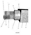
- Fig. 1 represents an overview of the medical device according to the present invention.
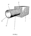
- Fig. 2 represents said medical device in rest configuration (pre-operative position with the electrode folded-up inside the main body of the device).
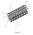
- Fig. 3a represents a detailed view of the bipolar electrode comprised in a device according to the invention, and including a needle shaped central pole and two cage-like helical poles.
- Fig 3b represents a front view of said cage-like helical poles.
- Fig. 4 represents the main body of a medical device provided with its stabilizing means, and shows the different degrees of freedom for said medical device.
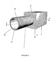
- Fig. 5 represents a medical device according to the invention, with its bipolar electrode in a first operating position, wherein the needle-like pole arranged inside a target volume and one helical pole deployed and arranged around said target,volume.
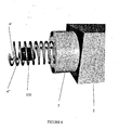
- Fig. 6 represents a medical device according to the invention, with its bipolar electrode in a second operating position, wherein two helical poles are deployed around said target volume.
- Fig. 7 illustrates an overview of a surgical system comprising the medical device according to the present invention which is linked to a robotic arm and controlling means, and is fixed via the robotic arm to a surgical table or floor.
- the medical device 1 comprises as elements a main body 2, stabilizing means 3, and a bipolar electrode 10.
- said device 1, as shown on Figure 7 is in fact part of an assembly comprising also controlling means.
- Said controlling means may advantageously comprise a robot supported by a robotic arm 6 and piloted by computerising means 7, for controlling the operating state of the device 1.
- the main body 2 and the stabilizing means 3 of the device 1 according to the invention have both a distal end, 20 and 30 respectively, and a proximal end 21 and 31 respectively.
- the main body 2 is attached by its distal end 20 to the proximal end 31 of the stabilizing device 3, while its proximal end 21 can be attached to the robotic arm 6 of a robot.
- the stabilizing means 3 is configured so as to allow its positioning at the outer surface of a target volume or organ in operating conditions, thereby contributing to the stabilisation of said target relatively to the device.
- the stabilising means 3 may have a hollow cylindrical shape, with its walls delimiting an internal cavity 33 and a more external cavity 32.
- the bipolar electrode 10, as further shown on Figure 1 comprises a central needle 5.
- the needle 5 of the electrode 10 has a distal end 51 in the form of a tip so as to be able to penetrate inside a target tissue volume in operating conditions.
- Said needle 5 has also a proximal end 52, by which the needle 5 of the electrode 10 may be linked to an external radio-frequency (RF) source or generator so as to constitute a passive pole of the electrode 10 that is to say in operating conditions an electric or electromagnetic current provided by the radiofrequency generator may flow towards it.
- RF radio-frequency
- the bipolar electrode 10 also comprises at least two helical or coiled elements 4' , 4"... which are concentric helices able to surround the needle 5 and to form a cage-like structure around said needle 5, when deployed according to a working configuration (see hereafter).
- Each of said helices is defined by its diameter D and its length L.
- Another feature characterizing an helix is its pitch P.
- the diameter D of all the helical elements 4', 4", ... are a multiple of a distance d, d being the diameter of the smallest helix, i.e. the distance between the smallest helical elements 4' and the main axis A of the needle 5.
- this distance d can be different depending on the embodiment of the medical device 1 and on the target organ (prostate, kidneys, breast, ...) to be treated and its anatomical features (size and shape, namely).
- Each of the helical elements 4', 4", ... of the electrode 10 has a distal end 41', 41", ... and a proximal end 42' , 42", ....
- the proximal ends 42', 42", ... are linked to the external radio frequency (RF) generator, while the distal ends 41', 41", ... are free.
- RF radio frequency
- an internal face 43' , 43", ... arranged towards the central needle 5 and an external face 44', 44", ... arranged towards the outside environment can be defined.
- only the internal faces 43', 43", ... of said helical elements are activatable separately and independently by the controlling means so that the internal face of one of said helices may constitute the first pole of the electrode 10, that is to say in operating conditions, an electric or electromagnetic current flows from it to the area of the bipolar electrode forming the second pole.
- each of the external faces 44', 44", ... of the helical elements 4' , 4", ... are susceptible to form the second pole of the electrode 10, so that in operating conditions an electric or electromagnetic current may flow from the first pole to the external face of one of the helices forming the second pole.
- the second pole of the bipolar electrode 10 may also be formed by the central needle 5.
- the helices are activable separately and independently by the controlling means on both their internal faces 43', 43", ... and their external faces 44', 44", ... so that one of said helix may constitute the first pole of the electrode 10, that is to say in operating conditions, an electric or electromagnetic current flows from it to the area of the bipolar electrode forming the second pole.
- the second pole may be formed either by another helix of smaller diameter than the helix forming the first pole, or by the central needle 5.
- composition of the helices is adapted according to the activation scheme to be achieved.
- the helices are entirely made of an adequate biocompatible and conducting metallic component.
- the helices are activable only on their internal face, only said internal face is made of such a metallic conducting component, while the external faces of the helices is made of an adequate biocompatible and isolating polymeric component.
- the helices are activatable either along their full length or only along at least one fraction of said length. It means that in the case wherein the helices are activatable only on one or more fractions of their length an adequate isolation pattern of the helices has to be provided.
- the device 1 may adopt at least one rest configuration as shown on Figure 2 , wherein, the bipolar electrode 10 (needle 5 + helices 4',4", ...) is folded up inside the main body 2 and the stabilising means 3 (bipolar electrode hidden from the outside environment) and wherein the bipolar electrode 10 cannot be activated (is unactivatable).
- the bipolar electrode 10 needle 5 + helices 4',4", Certainly is folded up inside the main body 2 and the stabilising means 3 (bipolar electrode hidden from the outside environment) and wherein the bipolar electrode 10 cannot be activated (is unactivatable).
- both the ends 41', 41", ... and 42', 42", ... of the helices 4',4", ... are folded up inside the stabilizing device 3 and main body 2.
- the medical device 1 in rest configuration, presents different degrees of freedom.
- the device 1 may also adopt at least one working configuration, wherein the bipolar electrode 10 (needle 5 and at least one helix 4') protrudes outside the stabilising means, beyond the distal end 30 of said stabilising means 3.
- the distal ends 41', 41", ... of the helical elements 4',4", ... can be deployed out from the stabilizing device 3, while the proximal ends 42', 42", ... of said helical elements remains inside the stabilizing device 3 and main body 2.
- the bipolar electrode 10 is activatable. It means that the bipolar electrode can be activated or not, depending on its activation state.
- the device 1 is such that only the bipolar electrode 10 is able to move, the needle 5 presenting one degree of freedom, which corresponds to a translation along the X axis, while the helices 4', 4", ... of the electrode 10 are able to perform a translation along the X axis and/or rotation around the X axis.
- the working configurations of the medical device 1 differ from each other at least by a different orientation of the bipolar electrode 10 that is to say of the needle 5 and/or of the helices 4',4", ..., relatively to the main body 2 in the referential system mentioned hereabove (see Figure 6 ).
- both movements allows in operating conditions the positioning of the helices 4', 4", ... of the electrode 10 around a target volume (target tumor or tumoral target region) with one unique entry point into the organ, following a corkscrew-like movement.
- the medical device 1 of the invention is conceived in such a manner that the movements of the main body 2 and of the stabilisation means 3 are locked before the needle 5 and the helices 4', 4" *... of the electrode 10 can move. It means that in working configuration, the main body 2 and the stabilising means 3 cannot move. In addition, it is also possible to lock the robotic arm 6 of the assembly.
- All these movements of the medical device 1 are done with a near millimeter precision, under the control of the controlling means.
- all these movements are done via the robotic arm 6 of a robot and by means of different activators and micro-activators.
- all the activators or micro-activators necessary for these movements can be placed in the main body 2 of-the device 1, or in the robotic arm 6 or somewhere else in the assembly itself.
- activators and micro-activators necessary for the described movements of the medical device 1 can be of several types, including electrostatic, magnetic, piezo-electric, thermic, shape memory allow (SMA), fluidic and electro-rheologic ones
- An important feature of the present device is the fact that the configuration the device 1, as well as the activation state of the bipolar electrode are contrallable by the controlling means.
- composition and dimensions of the different elements of the device 1 i.e. the main body 2, the stabilizing device 3, the needle 5 or other equivalent anchoring member and the helices 4', 4", ... of the electrode 10 are compatible with their technical use (the prostate, kidneys, adrenal glands, lungs, etc%), in particular in terms of biocompatibility, and can be easily adapted from the present description by the man skilled in the art.
- the anchoring member (needle 5) and the helices 4',4", ... always work together so as to form the bipolar electrode 10, with the electric or electromagnetic current flowing from the more external pole (the first pole) to the more internal pole (second pole) as defined hereabove.
- This movement of the current from the periphery to the center of the medical device allows a better control of the region to be destroyed by heating.
- the present apparatus and associated process thus prevent undesirable heating of the surrounding tissues located immediately outside the active helix.
- the controlling means and thus possibly the robot control the different elements of the device in such a manner that in the working configuration the needle 5 and the smallest helix 4' protrude outside the main body and stabilising means 3, the needle 5 penetrating inside the target volume 100 and the helix 4' wrapping said target volume 100, while helix 4" of greater diameter is folded up inside the main body 2 and stabilising means 3.
- the needle 5 operates as a second pole, while the internal face 43' of the smallest helix 4' operates as the first pole and the external face 44' of said helix 4' remains inactive i.e. is not activated by the RF external generator.
- the target volume 100 to be destroyed by heating is bigger than the diameter of the smallest helix 4'. Therefore, the controlling means and thus possibly the robot control the device in such a manner that the needle 5 as anchoring member and the helices 4', 4" protrude outside the main body 2 and stabilising means 3, the needle 5 and the helix 4' penetrating inside the' target volume 100 and the helix 4" wrapping said target volume 100.
- the second pole is the external face 44' of the smallest helix 4' and the first pole is the internal face 43" of the immediately bigger helix 4". (The other faces of the two helices 4' and 4", i.e. the internal face 43' of the smallest helix 4' and the external face 44" of the immediately biggest helix 4" are inactive, i.e. not activated by the external RF generator).
- the technical features of the device 1, and namely the number of helices 4' , 4" , 4"' , , 4"" , ... in the device 1, depend on the conception of said device 1 and can be adapted according to one or more target organs and their anatomical characteristics and specificities.
- the use of the device and assembly according to the invention can be done according to a process comprising the following steps, in the embodiment wherein the controlling means comprise a micro-robot.
- the robot orders the 3D navigation system to take informations such as images about the tumor and target organ. Said informations are treated by the robot (controlling means) so as to determine a surgical protocol (sequence in time of movements of the device 1, number of helices to be protruding, definition of the second and first poles, intensity and length of the activation of the electrode, ...) according to parameters including anatomical features (position, shape, size, ...) of the tumor and organ to be treated.
- a surgical protocol sequence in time of movements of the device 1, number of helices to be protruding, definition of the second and first poles, intensity and length of the activation of the electrode, .
- the surgeon introduces the medical device in rest configuration inside the patient using the 3D-navigation system which allows the monitoring in real time of the position of both the medical device and the target organ.
- the surgeon positions approximately the medical device relatively to the target organ and starts the automatic operating of the robot according to the predefined surgical protocol. The surgeon lets the robot operating but he has the possibility to monitor the whole surgical procedure through the navigation system.
- the robot Using its robotic arm 6 the robot readjust the position of the device, which is still in rest configuration, relatively to the target organ and namely the precise positionning of the stabilizing means 3 at the outer surface of the target organ so as to align the main axis X of the medical device 1 with the tumoral region 100 to be destroyed by heating.
- the stabilizing device 3 thus gives to the navigation system an important fixed point and allows an easier penetration of the electrode 10 into the patient's skin or organ's surface.
- the robot then orders the configuration change of the device into the working configuration, with the deployment of the needle 5 until it reaches the tumor or tumoral region center and the deployment of the smallest helix 4' in such a manner that said helix 4' may wrap the tumor or tumoral region 100 to be destroyed.
- the actuators responsible for this deployment and the degrees of freedom have been described above.
- the robot then activates the poles of the electrode 10 as described above in the first case.
- the robot orders the deployment of one or more additional helices 4"' , 4''', 4"", ... so as to completely wrap the tumoral region to be destroyed by heating.
- the activation of the helices is done as in the second case described above.
- the tumoral regions wrapped by the helical cage-like helices 4', 4" , 4"', ... of the electrode 10 are thus destroyed by heating, with no damage to surrounding tissues and only a few penetration points in the patient's skin or on the surface of the organ (the prostate, kidneys, adrenal glands, lungs, etc).
- the present device 1 thus requires a minimally invasive intervention.
- the robot 1 with its robotic arm 6 is provided with securing means activatable in case of abnormalities for interrupting the working of the robotic system so that the surgeon may continue manually the surgical procedure.
- the medical device of the present invention offers all the guarantees of security for the patient.
- the medical device 1 according to the present invention thus offer undeniable advantages over the state of the art.
Landscapes
- Health & Medical Sciences (AREA)
- Surgery (AREA)
- Engineering & Computer Science (AREA)
- Life Sciences & Earth Sciences (AREA)
- Biomedical Technology (AREA)
- Molecular Biology (AREA)
- Nuclear Medicine, Radiotherapy & Molecular Imaging (AREA)
- Plasma & Fusion (AREA)
- Physics & Mathematics (AREA)
- Heart & Thoracic Surgery (AREA)
- Medical Informatics (AREA)
- Otolaryngology (AREA)
- Animal Behavior & Ethology (AREA)
- General Health & Medical Sciences (AREA)
- Public Health (AREA)
- Veterinary Medicine (AREA)
- Surgical Instruments (AREA)
- Radiation-Therapy Devices (AREA)
Abstract
Description
- The present invention concerns the field of surgery, more particularly the field of cancer surgery and is related to a medical device or instrument.
- Most cancer cells first develop in a primary tumor site such as the breast, colon or lung, but then cells from these cancers can spread, or metastasize, to other parts of the body where they may form new tumors.
- A possible strategy for the treatment of cancer corresponds to a local treatment of the tumor, wherein cancer is attacked at a specific site. Different techniques have been developed on the basis of said strategy. Ablation surgery in order to remove tumors is certainly the most common local treatment used worldwide. However, other local treatment techniques also exist, among which is radiation therapy, wherein radioactive particles, seeds or rods implanted directly into a tumor are used. This type of radiation treatment is called brachytherapy.
- New local treatment techniques such as radio-frequency (RF) ablation procedure and other similar interventional radiology catheter ablation procedures reveal to be particularly promising for patients whose cancers cannot be treated surgically.
- The device used in the radiofrequency ablation technique generally comprises a needle which is placed through the skin and into the tumor. The needle is linked to a radiofrequency generator such that when a radiofrequency is sent through the needle, the needle is heated and destroys the tumor. This procedure is performed under conscious sedation and most patients can go home the same day.
- RF treatment presents several advantages:
- it is a new local treatment option for cancer;
- it is a minimally invasive method;
- its safety has been proven over many years in thousands of people;
- it is less risky and has fewer complications compared to surgery;
- generally, only local anesthesia is required;
- it may be done as an outpatient procedure, or shorten hospital stay;
- most patients can resume normal activities within a few days;
- it can be repeated if necessary;
- and it may be combined with other treatment options, such as chemotherapy.
- However, the capabilities of RF technique are nowadays limited as there is a real technical difficulty in controlling precisely the region to be destroyed with the existing RF devices. Indeed, the conception of said devices is such that the heating of the tissues tends to propagate beyond the tumour site. In some cases, cell's dehydration stops the heating propagation and then, the treatment's effectiveness. Currently, some cooled devices and expandable electrodes allows bigger regions to be destroyed. Then, increasing the destruction volume is possible, but the precise control of the destruction region becomes to be reached. This is important in some organs where the lesion of neighbour organs and structures, like important vessels, represents a real and still unsolved problem.
- Among the solutions proposed in the prior art in order to solve this problem, it has been suggested in document
US 5,507,743 to use a RF ablation device comprising a variable pitch helical electrode capable of wrapping the tumor. However, the use of said device presents a serious drawback from a practical point of view, as it is known that increasing the distance between the two poles of the electrode produces two undesirable effects. The first undesirable effect is that the physician must increase the RF generator power, so as to compensate the bigger distance to destroy. However, increasing the power heats the cells closer to the active electrode to temperatures as high as 90 or 100 Celsius degrees, dehydrating these cells and stopping the heating effect (the heating and consequently the destruction effect is propagated through the cell's water). The second undesirable effect is that more distant tissues are easily cooled by surrounding vessels, thereby increasing the risk of non destruction of all tumoral cells.US2002/0049439 discloses on RF ablation device with concentric helical electrodes. - In other words, there is still a need for a satisfying device which could be used in RF ablation techniques in order to destroy by heating a tumor site inside an organ.
- The present invention aims to provide a medical device or instrument and a process adapted for the ablation (i.e. destruction) by radiofrequency technique of a target volume, such as a tumor, located inside or at an anatomical organ such as prostate, kidney, adrenal glands, breast, lungs and pancreas, an even brain, which would not present the drawbacks of the solutions of the prior art.
- In particular, the present invention aims to provide a device and a process which would ensure, in operating conditions, a total but specific destruction of a predetermined unsafe tissue volume inside or at said organ, while preserving the surrounding safe tissues.
- Another aim of the present invention is to provide a device and a process which could be used or carried out both easily and securely.
- The invention is defined in appended
claim 1, preferred embodiments are described in the dependent claims. - The present invention is related to a medical device adapted for the ablation of a target volume inside an anatomical organ, said device comprising as elements a main body, stabilising means for stabilising the device relatively to the organ and heating means in the form, of a bipolar electrode comprising parts activatable by an external radiofrequency generator for heating said target volume, wherein said bipolar electrode comprises a first element having the form of a central anchoring member, and a second element having the form of at least two concentric helices of different predetermined diameter and of predetermined length, said helices surrounding the central anchoring member.
- Advantageously, said central anchoring member may take the form of a central needle or of an extremely thin helix.
- Preferably, said helices are rigid i.e. said helices are not deformable by simple external manual pressure (not deformable by direct manipulation).
- Preferably, the medical device can adopt at least one rest configuration wherein the bipolar electrode is unactivable and is folded-up inside the stabilising means and the main body, and at least one working configuration wherein the bipolar electrode protrudes outside the stabilisation means so as to deploy both the anchoring member and the helices, said helices thereby forming a cage-like structure around said anchoring member, with an internal face facing the central anchoring member and an external face oriented in an opposite manner (exposed to the environment), and wherein said bipolar electrode is activable so as to have a passive pole and an active pole.
- It is meant by "activation of the electrode" the circulation inside said electrode of a current of electric or electromagnetic type from one area of said electrode which forms the first pole to another area of said electrode which forms the second pole.
- According to a configuration not part of the invention, in the working configuration at least one of the helices is activatable independently from the others, only on its internal face, so as to form the first pole of the bipolar electrode, while the second pole of the bipolar electrode can be formed either by the central anchoring member or by the external face of the helix forming the active pole or by the external face of an helix of smaller diameter than the helix forming the active pole.
- According to the invention, in the working configuration at least one of the helices is activable independently from the others, on both its internal face and its external face, so as to form the first pole of the bipolar electrode, while the second pole of the bipolar electrode can be formed either by the central anchoring member or by a helix of smaller diameter than the helix forming the active pole.
- In the present invention, the helices of the medical device may be activatable at least on one fraction of their length, and possibly on their full length.
- Preferably, in the rest configuration, the device according to the invention has the following degrees of freedom in a referential system (O,X,Y,Z) centred at the centre of the main body:
- Rotation around the Z axis;
- Rotation around the Y axis;
- Translation along the X axis;
- Translation along the Y axis;
- Translation along the Z axis.
- Preferably, in the working configuration, the anchoring member of the bipolar electrode has one degree of freedom in a referential system (O,X,Y,Z) centred at the centre of the main body corresponding to a translation along the X axis, while the helices have two degrees of freedom each, one corresponding to a translation along the X axis, and the other to a rotation around the X axis.
- Preferably, in the working configuration any translation or rotational movement of the main body and of the stabilising means is blocked.
- Preferably, the medical device of the invention is conceived such that the positioning of its different elements relatively to the target volume and relatively to each other and the activation state of said parts of the bipolar electrode are able to be controlled by controlling means.
- Advantageously, said controlling means comprise a robot.
- The present invention is also related to a surgical assembly comprising the medical device according to any one of the preceding claims, coupled to controlling means.
- Preferably, said controlling means comprise a robot.
- Preferably, the surgical assembly further comprises a 3D-navigation system. It is meant by "3D-navigation system any device able to take 3D informations on the position in real time of an object such as a camera or ultrasound measurement device (echographic navigation system).
- Preferably the controlling means also comprise a computer coupled to the robot via interfacing means such as an A/D converter.
- Preferably, said assembly is linked to a fixed support such as a surgical table.
- Also described is a process for the destruction of a target volume inside an anatomical organ by radiofrequency ablation technique using the medical device or the surgical assembly as disclosed above, said process comprising the,following steps:
- determining parameters comprising at least the anatomical features (size, shape, position, ...) of the target volume to be treated;
- on the basis of said parameters, defining at least the number of helices to use in the bipolar electrode, the first and second poles of the bipolar electrode, the sequence of activation of the bipolar electrode, and the intensity and time of activation of said bipolar electrode;
- introducing said medical device inside the patient;
- once the target organ is reached, positioning the medical device relatively to the target volume;
- performing the treatment procedure of the target tumor following the predetermined parameters.
- The present disclosure also concerns a process for the destruction of a target volume inside an anatomical organ by radiofrequency ablation technique using the medical device or the surgical assembly disclosed hereabove.
- , Preferably, said process comprises the following steps:
- by means of the 3D navigation system,
- establishing a surgical protocol according to different parameters including the anatomical features of the target volume to be treated, said surgical protocol defining namely the sequence and type of movements of the medical device and of its different elements, the number of helices to use in the bipolar electrode, the definition of the first and second poles of the bipolar electrode, the sequence of activation of the bipolar electrode, the intensity and time of activation of said bipolar electrode;
- manually introducing said medical device inside the patient and approximately positioning said device relatively to the target volume;
- starting the automatic operating of the robot so as to perform the surgical procedure under automatic control following the pre-established surgical protocol;
- monitoring the surgical procedure and possibly restoring a manual control on the device, in case of security problems.
- The present disclosure also concerns the use of said medical device or said surgical assembly for the treatment of a target volume inside an anatomical organ selected from the group consisting of kidneys" lungs, liver, breast, prostate and brain.
-
Fig. 1 represents an overview of the medical device according to the present invention. -
Fig. 2 represents said medical device in rest configuration (pre-operative position with the electrode folded-up inside the main body of the device). -
Fig. 3a represents a detailed view of the bipolar electrode comprised in a device according to the invention, and including a needle shaped central pole and two cage-like helical poles. -
Fig 3b represents a front view of said cage-like helical poles. -
Fig. 4 represents the main body of a medical device provided with its stabilizing means, and shows the different degrees of freedom for said medical device. -
Fig. 5 represents a medical device according to the invention, with its bipolar electrode in a first operating position, wherein the needle-like pole arranged inside a target volume and one helical pole deployed and arranged around said target,volume. -
Fig. 6 represents a medical device according to the invention, with its bipolar electrode in a second operating position, wherein two helical poles are deployed around said target volume. -
Fig. 7 illustrates an overview of a surgical system comprising the medical device according to the present invention which is linked to a robotic arm and controlling means, and is fixed via the robotic arm to a surgical table or floor. - As illustrated on
Figure 1 , themedical device 1 according to the invention comprises as elements amain body 2, stabilizingmeans 3, and abipolar electrode 10. - Advantageously but not necessarily, said
device 1, as shown onFigure 7 , is in fact part of an assembly comprising also controlling means. Said controlling means may advantageously comprise a robot supported by arobotic arm 6 and piloted by computerisingmeans 7, for controlling the operating state of thedevice 1. - The
main body 2 and the stabilizingmeans 3 of thedevice 1 according to the invention have both a distal end, 20 and 30 respectively, and aproximal end - The
main body 2 is attached by itsdistal end 20 to theproximal end 31 of the stabilizingdevice 3, while itsproximal end 21 can be attached to therobotic arm 6 of a robot. - The stabilizing means 3 is configured so as to allow its positioning at the outer surface of a target volume or organ in operating conditions, thereby contributing to the stabilisation of said target relatively to the device. For example, as shown on
Figure 1 and more detailed onFigure 4 , the stabilising means 3 may have a hollow cylindrical shape, with its walls delimiting aninternal cavity 33 and a moreexternal cavity 32. - The
bipolar electrode 10, as further shown onFigure 1 , comprises acentral needle 5. Theneedle 5 of theelectrode 10 has adistal end 51 in the form of a tip so as to be able to penetrate inside a target tissue volume in operating conditions.Said needle 5 has also aproximal end 52, by which theneedle 5 of theelectrode 10 may be linked to an external radio-frequency (RF) source or generator so as to constitute a passive pole of theelectrode 10 that is to say in operating conditions an electric or electromagnetic current provided by the radiofrequency generator may flow towards it. - The
bipolar electrode 10 also comprises at least two helical orcoiled elements 4' , 4"... which are concentric helices able to surround theneedle 5 and to form a cage-like structure around saidneedle 5, when deployed according to a working configuration (see hereafter). Each of said helices is defined by its diameter D and its length L. Another feature characterizing an helix is its pitch P. - Preferably, the diameter D of all the
helical elements 4', 4", ... are a multiple of a distance d, d being the diameter of the smallest helix, i.e. the distance between the smallest helical elements 4' and the main axis A of theneedle 5. - According to the present invention, this distance d can be different depending on the embodiment of the
medical device 1 and on the target organ (prostate, kidneys, breast, ...) to be treated and its anatomical features (size and shape, namely). - Each of the
helical elements 4', 4", ... of theelectrode 10 has adistal end 41', 41", ... and aproximal end 42' , 42", .... The proximal ends 42', 42", ... are linked to the external radio frequency (RF) generator, while the distal ends 41', 41", ... are free. - As illustrated in
figure 3b , for each of saidhelical elements 4' , 4" ..., aninternal face 43' , 43", ... arranged towards thecentral needle 5 and anexternal face 44', 44", ... arranged towards the outside environment can be defined. - According to a first configuration not part of the invention, only the internal faces 43', 43", ... of said helical elements are activatable separately and independently by the controlling means so that the internal face of one of said helices may constitute the first pole of the
electrode 10, that is to say in operating conditions, an electric or electromagnetic current flows from it to the area of the bipolar electrode forming the second pole. - On the contrary, each of the external faces 44', 44", ... of the
helical elements 4' , 4", ... are susceptible to form the second pole of theelectrode 10, so that in operating conditions an electric or electromagnetic current may flow from the first pole to the external face of one of the helices forming the second pole. - In this first configuration, the second pole of the
bipolar electrode 10 may also be formed by thecentral needle 5. - According to the configuration according to the invention, the helices are activable separately and independently by the controlling means on both their
internal faces 43', 43", ... and theirexternal faces 44', 44", ... so that one of said helix may constitute the first pole of theelectrode 10, that is to say in operating conditions, an electric or electromagnetic current flows from it to the area of the bipolar electrode forming the second pole. - In said second embodiment, the second pole may be formed either by another helix of smaller diameter than the helix forming the first pole, or by the
central needle 5. - It should be noted that the composition of the helices is adapted according to the activation scheme to be achieved. For example, in the invention, wherein the the helices are activable on both faces, the helices are entirely made of an adequate biocompatible and conducting metallic component. Comparatively, in the first configuration not part of the invention, wherein the helices are activable only on their internal face, only said internal face is made of such a metallic conducting component, while the external faces of the helices is made of an adequate biocompatible and isolating polymeric component.
- It should be noted that in both configurations, the helices are activatable either along their full length or only along at least one fraction of said length. It means that in the case wherein the helices are activatable only on one or more fractions of their length an adequate isolation pattern of the helices has to be provided.
- According to the invention, the
device 1 may adopt at least one rest configuration as shown onFigure 2 , wherein, the bipolar electrode 10 (needle 5 +helices 4',4", ...) is folded up inside themain body 2 and the stabilising means 3 (bipolar electrode hidden from the outside environment) and wherein thebipolar electrode 10 cannot be activated (is unactivatable). - It means that in - said rest configuration, both the
ends 41', 41", ... and 42', 42", ... of thehelices 4',4", ... are folded up inside the stabilizingdevice 3 andmain body 2. - Moreover, in rest configuration, the
medical device 1 as a whole presents different degrees of freedom. - More precisely, as illustrated on
Figure 4 , in the referential system (O, X, Y, Z) centred at the centre O of themain body 2 of themedical device 1, the following degrees of freedom are associated to the medical device 1: - rotation around the Z axis;
- rotation around the Y axis;
- translation along the X axis;
- translation along the Y axis;
- translation along the Z axis.
- According to the invention, the
device 1 may also adopt at least one working configuration, wherein the bipolar electrode 10 (needle 5 and at least one helix 4') protrudes outside the stabilising means, beyond thedistal end 30 of said stabilising means 3. The distal ends 41', 41", ... of thehelical elements 4',4", ... can be deployed out from the stabilizingdevice 3, while the proximal ends 42', 42", ... of said helical elements remains inside the stabilizingdevice 3 andmain body 2. In addition, in working configuration thebipolar electrode 10 is activatable. It means that the bipolar electrode can be activated or not, depending on its activation state. - An example of such a working configuration is represented on
Figure 1 . - In said working configuration, the
device 1 is such that only thebipolar electrode 10 is able to move, theneedle 5 presenting one degree of freedom, which corresponds to a translation along the X axis, while thehelices 4', 4", ... of theelectrode 10 are able to perform a translation along the X axis and/or rotation around the X axis. - Therefore, the working configurations of the
medical device 1 differ from each other at least by a different orientation of thebipolar electrode 10 that is to say of theneedle 5 and/or of thehelices 4',4", ..., relatively to themain body 2 in the referential system mentioned hereabove (seeFigure 6 ). - It should be noted that the combination of both movements (translation + rotation around X axis) allows in operating conditions the positioning of the
helices 4', 4", ... of theelectrode 10 around a target volume (target tumor or tumoral target region) with one unique entry point into the organ, following a corkscrew-like movement. - It should also be noted that the
medical device 1 of the invention is conceived in such a manner that the movements of themain body 2 and of the stabilisation means 3 are locked before theneedle 5 and thehelices 4', 4" *... of theelectrode 10 can move. It means that in working configuration, themain body 2 and the stabilising means 3 cannot move. In addition, it is also possible to lock therobotic arm 6 of the assembly. - All these movements of the
medical device 1 are done with a near millimeter precision, under the control of the controlling means. - Advantageously, all these movements are done via the
robotic arm 6 of a robot and by means of different activators and micro-activators. - In this case, all the activators or micro-activators necessary for these movements can be placed in the
main body 2 of-thedevice 1, or in therobotic arm 6 or somewhere else in the assembly itself. - These activators and micro-activators necessary for the described movements of the
medical device 1 can be of several types, including electrostatic, magnetic, piezo-electric, thermic, shape memory allow (SMA), fluidic and electro-rheologic ones - An important feature of the present device is the fact that the configuration the
device 1, as well as the activation state of the bipolar electrode are contrallable by the controlling means. - Furthermore, it should be noted that the composition and dimensions of the different elements of the
device 1 i.e. themain body 2, the stabilizingdevice 3, theneedle 5 or other equivalent anchoring member and thehelices 4', 4", ... of theelectrode 10 are compatible with their technical use (the prostate, kidneys, adrenal glands, lungs, etc...), in particular in terms of biocompatibility, and can be easily adapted from the present description by the man skilled in the art. - In practice, the anchoring member (needle 5) and the
helices 4',4", ... always work together so as to form thebipolar electrode 10, with the electric or electromagnetic current flowing from the more external pole (the first pole) to the more internal pole (second pole) as defined hereabove. - This movement of the current from the periphery to the center of the medical device allows a better control of the region to be destroyed by heating. The present apparatus and associated process thus prevent undesirable heating of the surrounding tissues located immediately outside the active helix.
- In a first case, as illustrated in
figure 5 , wherein the target volume 100 (target tumor or tumoral region) is sufficiently small, the controlling means and thus possibly the robot, control the different elements of the device in such a manner that in the working configuration theneedle 5 and the smallest helix 4' protrude outside the main body and stabilising means 3, theneedle 5 penetrating inside thetarget volume 100 and the helix 4' wrapping saidtarget volume 100, whilehelix 4" of greater diameter is folded up inside themain body 2 and stabilising means 3. Theneedle 5 operates as a second pole, while the internal face 43' of the smallest helix 4' operates as the first pole and the external face 44' of said helix 4' remains inactive i.e. is not activated by the RF external generator. - In a second case, as illustrated in
figure 6 , thetarget volume 100 to be destroyed by heating is bigger than the diameter of the smallest helix 4'. Therefore, the controlling means and thus possibly the robot control the device in such a manner that theneedle 5 as anchoring member and thehelices 4', 4" protrude outside themain body 2 and stabilising means 3, theneedle 5 and the helix 4' penetrating inside the'target volume 100 and thehelix 4" wrapping saidtarget volume 100. The second pole is the external face 44' of the smallest helix 4' and the first pole is theinternal face 43" of the immediatelybigger helix 4". (The other faces of the twohelices 4' and 4", i.e. the internal face 43' of the smallest helix 4' and theexternal face 44" of the immediatelybiggest helix 4" are inactive, i.e. not activated by the external RF generator). - Similarly, if necessary, it is possible to destroy even
bigger target volumes 100 by deploying and activating through the controlling meansother helices 4"', 4""... , of bigger diameter as mentioned previously. So, the technical features of thedevice 1, and namely the number ofhelices 4' , 4" , 4"' , , 4"" , ... in thedevice 1, depend on the conception of saiddevice 1 and can be adapted according to one or more target organs and their anatomical characteristics and specificities. - It is thus possible to adapt the diameter of the helix to the volume of the target volume by selecting the appropriate external helix.
- In practice, the use of the device and assembly according to the invention can be done according to a process comprising the following steps, in the embodiment wherein the controlling means comprise a micro-robot.
- Before the surgery, the robot orders the 3D navigation system to take informations such as images about the tumor and target organ. Said informations are treated by the robot (controlling means) so as to determine a surgical protocol (sequence in time of movements of the
device 1, number of helices to be protruding, definition of the second and first poles, intensity and length of the activation of the electrode, ...) according to parameters including anatomical features (position, shape, size, ...) of the tumor and organ to be treated. - During the surgery, the surgeon introduces the medical device in rest configuration inside the patient using the 3D-navigation system which allows the monitoring in real time of the position of both the medical device and the target organ. Once the target organ is reached, the surgeon positions approximately the medical device relatively to the target organ and starts the automatic operating of the robot according to the predefined surgical protocol. The surgeon lets the robot operating but he has the possibility to monitor the whole surgical procedure through the navigation system.
- Using its
robotic arm 6 the robot readjust the position of the device, which is still in rest configuration, relatively to the target organ and namely the precise positionning of the stabilizingmeans 3 at the outer surface of the target organ so as to align the main axis X of themedical device 1 with thetumoral region 100 to be destroyed by heating. - The stabilizing
device 3 thus gives to the navigation system an important fixed point and allows an easier penetration of theelectrode 10 into the patient's skin or organ's surface. - The robot then orders the configuration change of the device into the working configuration, with the deployment of the
needle 5 until it reaches the tumor or tumoral region center and the deployment of the smallest helix 4' in such a manner that said helix 4' may wrap the tumor ortumoral region 100 to be destroyed. The actuators responsible for this deployment and the degrees of freedom have been described above. - The robot then activates the poles of the
electrode 10 as described above in the first case. - When the tumor or
tumoral region 100 is bigger than the diameter of the smallest helix 4', the robot orders the deployment of one or moreadditional helices 4"' , 4''', 4"", ... so as to completely wrap the tumoral region to be destroyed by heating. The activation of the helices is done as in the second case described above. - The tumoral regions wrapped by the helical cage-
like helices 4', 4" , 4"', ... of theelectrode 10 are thus destroyed by heating, with no damage to surrounding tissues and only a few penetration points in the patient's skin or on the surface of the organ (the prostate, kidneys, adrenal glands, lungs, etc...). Thepresent device 1 thus requires a minimally invasive intervention. - It should be noted that the
robot 1 with itsrobotic arm 6 is provided with securing means activatable in case of abnormalities for interrupting the working of the robotic system so that the surgeon may continue manually the surgical procedure. - In this manner, the medical device of the present invention offers all the guarantees of security for the patient.
- As illustrated hereabove, the
medical device 1 according to the present invention thus offer undeniable advantages over the state of the art.
Claims (13)
- A medical device (1) adapted for the ablation of a target volume inside an anatomical organ, said medical device (1) comprising as elements a main body (2), stabilising means (3) for stabilising the medical device relatively to the organ and heating means in the form of a bipolar electrode (10) comprising parts activable by an external radiofrequency generator for heating said target volume, wherein said bipolar electrode (10) comprises a first element having the form of a central anchoring member (5), and a second element having the form of at least two concentric rigid helices (4',4", ...) of different predetermined diameters (D) and predetermined length (L), said helices surrounding the central anchoring member (5) to form a cage-like structure around said anchoring member (5) when deployed according to a working configuration, one of the helices being activatable independently so as to form a first pole while a second pole is formed either by the central anchoring member or by the helix of smaller diameter than the helix forming the first pole.
- The medical device according to claim 1, wherein the central anchoring member is a central needle (5) .
- The medical device according to claim 1, wherein the central anchoring member is a central helix.
- The medical device according to any one of claims 1 to 3, wherein said medical device may adopt at least one rest configuration wherein the bipolar electrode (10) is unactivable and is folded-up inside the stabilising means (3) and the main body (2), and at least one working configuration wherein said bipolar electrode (10) is activable and protrudes outside the stabilisation means so as to deploy both the anchoring member (5) and the helices (4' , 4"), said helices forming a cage-like structure around said anchoring member (5), with an internal face facing the central anchoring member (5) and an external face oriented in an opposite manner.
- The medical device according to any one of the preceding claims, wherein the helices are activable at least on one fraction of their length.
- The medical device according to any one of the preceding claims, wherein the helices are activable on their full length.
- The medical device according to any one of the preceding claims, wherein in the rest configuration, said medical device (1) has the following degrees of freedom in a referential system (O,X,Y,Z) centred at the centre of the main body (2):- Rotation around the Z axis;- Rotation around the Y axis;- Translation along the X axis;- Translation along the Y axis;- Translation along the Z axis.
- The medical device according to any one of the preceding claims, wherein in the working configuration, the medical device is such that the anchoring member (5) of the bipolar electrode (10) has one degree of freedom in a referential system (O,X,Y,Z) centred at the centre of the main body (2) corresponding to a translation along the X axis, while the helices (4',4") have two degrees of freedom, one corresponding to a translation along the X axis, and the other to a rotation around the X axis.
- The medical device according to any one of the preceding claims, in the working configuration any translation or rotational movement of the main body (2) and of the stabilising means (3) is blocked.
- The medical device according to any one of the preceding claims being conceived such that the positioning of the different elements of said medical device relatively to the target volume and relatively to each other and the activation state of said parts of the bipolar electrode are able to be controlled by controlling means.
- The medical device according to claim 10 wherein the controlling means comprise a robot, preferably coupled to a 3D-navigation system and to a computer.
- A surgical assembly comprising the medical device according to any one of the preceding claims, coupled to controlling means, said controlling means, preferably comprising a robot.
- A surgical assembly according to claim 12, further comprising a 3D navigation system and/or a computer and/or interfacing means.
Applications Claiming Priority (2)
| Application Number | Priority Date | Filing Date | Title |
|---|---|---|---|
| US47108303P | 2003-05-16 | 2003-05-16 | |
| PCT/BE2004/000073 WO2004100812A1 (en) | 2003-05-16 | 2004-05-17 | Medical device using a coiled electrode |
Publications (3)
| Publication Number | Publication Date |
|---|---|
| EP1631209A1 EP1631209A1 (en) | 2006-03-08 |
| EP1631209B1 true EP1631209B1 (en) | 2009-03-25 |
| EP1631209B2 EP1631209B2 (en) | 2015-10-07 |
Family
ID=33452428
Family Applications (1)
| Application Number | Title | Priority Date | Filing Date |
|---|---|---|---|
| EP04733277.0A Expired - Lifetime EP1631209B2 (en) | 2003-05-16 | 2004-05-17 | Medical device using a coiled electrode |
Country Status (6)
| Country | Link |
|---|---|
| US (1) | US8317785B2 (en) |
| EP (1) | EP1631209B2 (en) |
| AT (1) | ATE426368T1 (en) |
| DE (1) | DE602004020217D1 (en) |
| ES (1) | ES2324613T5 (en) |
| WO (1) | WO2004100812A1 (en) |
Families Citing this family (33)
| Publication number | Priority date | Publication date | Assignee | Title |
|---|---|---|---|---|
| US6306132B1 (en) | 1999-06-17 | 2001-10-23 | Vivant Medical | Modular biopsy and microwave ablation needle delivery apparatus adapted to in situ assembly and method of use |
| US7197363B2 (en) | 2002-04-16 | 2007-03-27 | Vivant Medical, Inc. | Microwave antenna having a curved configuration |
| US6752767B2 (en) | 2002-04-16 | 2004-06-22 | Vivant Medical, Inc. | Localization element with energized tip |
| US9655676B2 (en) | 2003-05-16 | 2017-05-23 | Trod Medical | Method of percutaneous localized or focal treatment of prostate lesions using radio frequency |
| US7311703B2 (en) | 2003-07-18 | 2007-12-25 | Vivant Medical, Inc. | Devices and methods for cooling microwave antennas |
| DE102005062657A1 (en) | 2005-12-28 | 2007-07-12 | Osypka, Peter, Dr.-Ing. | Device for closing an opening located in a heart separation wall |
| DE102005062658B3 (en) * | 2005-12-28 | 2007-05-31 | Osypka, Peter, Dr.-Ing. | Device for occluding opening between two heart chambers formed by two overlapping tissue lobes in heart, has connecting mechanism which has screw catheter that dilates at its distal end and is movable into feed catheter |
| US8073551B2 (en) | 2006-04-04 | 2011-12-06 | University Health Network | Coil electrode apparatus for thermal therapy |
| US8068921B2 (en) | 2006-09-29 | 2011-11-29 | Vivant Medical, Inc. | Microwave antenna assembly and method of using the same |
| WO2009036457A1 (en) * | 2007-09-14 | 2009-03-19 | Lazure Technologies, Llc | Multi-layer electrode ablation probe and related methods |
| US8292880B2 (en) | 2007-11-27 | 2012-10-23 | Vivant Medical, Inc. | Targeted cooling of deployable microwave antenna |
| EP2320820B1 (en) * | 2008-05-16 | 2014-03-19 | Trod Medical | Percutaneous and laparoscopic surgical instrument |
| WO2012100355A1 (en) | 2011-01-30 | 2012-08-02 | University Health Network | Coil electrode for thermal therapy |
| EP2674109A1 (en) * | 2012-06-15 | 2013-12-18 | Endo Tools Therapeutics S.A. | Endoscopic surgical apparatus |
| US20140031715A1 (en) * | 2012-07-30 | 2014-01-30 | Michael David SHERAR | Coil electrode apparatus for thermal therapy for treating bone tissue |
| US10499980B2 (en) * | 2013-03-14 | 2019-12-10 | Spiration, Inc. | Flexible RF ablation needle |
| CN106028972A (en) * | 2014-03-12 | 2016-10-12 | 奥林巴斯株式会社 | Treatment device and treatment system |
| RU2628645C2 (en) * | 2015-12-08 | 2017-08-21 | Федеральное государственное бюджетное образовательное учреждение высшего образования "Санкт-Петербургский государственный университет" (СПбГУ) | Method for treatment of hormone-active tumours of adrenal glands |
| AU2017345734B2 (en) * | 2016-10-21 | 2023-04-13 | Mako Surgical Corp. | Systems and tools for use with surgical robotic manipulators |
| CN107495964A (en) * | 2017-09-15 | 2017-12-22 | 西安富德医疗电子有限公司 | Disposable medical spiral pin electrode |
| US20200038089A1 (en) * | 2018-07-31 | 2020-02-06 | Ethicon, Inc. | Tissue resection apparatus |
| CN111329579B (en) * | 2018-12-18 | 2022-10-04 | 上海蓝盎医学科技发展有限公司 | Multilayer concentric electrode |
| US10667855B1 (en) * | 2019-05-10 | 2020-06-02 | Trod Medical Us, Llc | Dual coil ablation devices |
| US11779394B2 (en) | 2020-01-30 | 2023-10-10 | Covidien Lp | Single-sided low profile end effector for bipolar pencil |
| US11596467B2 (en) | 2020-02-04 | 2023-03-07 | Covidien Lp | Articulating tip for bipolar pencil |
| US11944367B2 (en) | 2020-02-05 | 2024-04-02 | Covidien Lp | Electrosurgical device for cutting tissue |
| US11864815B2 (en) | 2020-02-06 | 2024-01-09 | Covidien Lp | Electrosurgical device for cutting tissue |
| US11864817B2 (en) | 2020-02-13 | 2024-01-09 | Covidien Lp | Low profile single pole tip for bipolar pencil |
| US11712285B2 (en) | 2020-04-23 | 2023-08-01 | Covidien Lp | Dual-threaded tensioning mechanism for bipolar pencil |
| US11648046B2 (en) | 2020-04-29 | 2023-05-16 | Covidien Lp | Electrosurgical instrument for cutting tissue |
| US11684413B2 (en) | 2020-05-22 | 2023-06-27 | Covidien Lp | Smoke mitigation assembly for bipolar pencil |
| US11864818B2 (en) | 2020-06-12 | 2024-01-09 | Covidien Lp | End effector assembly for bipolar pencil |
| CN116723805A (en) * | 2020-08-17 | 2023-09-08 | 普拉纳胸科公司 | Coring and truncation apparatus, systems and methods |
Family Cites Families (11)
| Publication number | Priority date | Publication date | Assignee | Title |
|---|---|---|---|---|
| US5921982A (en) * | 1993-07-30 | 1999-07-13 | Lesh; Michael D. | Systems and methods for ablating body tissue |
| US5507743A (en) | 1993-11-08 | 1996-04-16 | Zomed International | Coiled RF electrode treatment apparatus |
| US6641580B1 (en) * | 1993-11-08 | 2003-11-04 | Rita Medical Systems, Inc. | Infusion array ablation apparatus |
| US5676662A (en) * | 1995-03-17 | 1997-10-14 | Daig Corporation | Ablation catheter |
| US6165170A (en) * | 1998-01-29 | 2000-12-26 | International Business Machines Corporation | Laser dermablator and dermablation |
| FR2779339B1 (en) * | 1998-06-09 | 2000-10-13 | Integrated Surgical Systems Sa | MATCHING METHOD AND APPARATUS FOR ROBOTIC SURGERY, AND MATCHING DEVICE COMPRISING APPLICATION |
| US6537248B2 (en) * | 1998-07-07 | 2003-03-25 | Medtronic, Inc. | Helical needle apparatus for creating a virtual electrode used for the ablation of tissue |
| DE69917484T2 (en) | 1998-12-14 | 2005-05-12 | Tre Esse Progettazione Biomedica S.R.L. | CATHETER SYSTEM FOR CARRYING OUT INTRAMYOCARDIAL THERAPEUTIC TREATMENT |
| US6638275B1 (en) * | 2000-10-05 | 2003-10-28 | Medironic, Inc. | Bipolar ablation apparatus and method |
| US6497704B2 (en) † | 2001-04-04 | 2002-12-24 | Moshe Ein-Gal | Electrosurgical apparatus |
| US7879030B2 (en) * | 2005-07-27 | 2011-02-01 | St. Jude Medical, Atrial Fibrillation Division, Inc. | Multipolar, virtual-electrode catheter with at least one surface electrode and method for ablation |
-
2004
- 2004-05-17 ES ES04733277.0T patent/ES2324613T5/en not_active Expired - Lifetime
- 2004-05-17 WO PCT/BE2004/000073 patent/WO2004100812A1/en active Application Filing
- 2004-05-17 DE DE602004020217T patent/DE602004020217D1/en not_active Expired - Lifetime
- 2004-05-17 US US10/556,770 patent/US8317785B2/en active Active
- 2004-05-17 EP EP04733277.0A patent/EP1631209B2/en not_active Expired - Lifetime
- 2004-05-17 AT AT04733277T patent/ATE426368T1/en not_active IP Right Cessation
Also Published As
| Publication number | Publication date |
|---|---|
| US20070179494A1 (en) | 2007-08-02 |
| ES2324613T5 (en) | 2016-01-28 |
| US8317785B2 (en) | 2012-11-27 |
| DE602004020217D1 (en) | 2009-05-07 |
| EP1631209A1 (en) | 2006-03-08 |
| EP1631209B2 (en) | 2015-10-07 |
| ATE426368T1 (en) | 2009-04-15 |
| WO2004100812A1 (en) | 2004-11-25 |
| ES2324613T3 (en) | 2009-08-11 |
Similar Documents
| Publication | Publication Date | Title |
|---|---|---|
| EP1631209B1 (en) | Medical device using a coiled electrode | |
| US20200323588A1 (en) | Multiple Treatment Zone Ablation Probe | |
| US8753335B2 (en) | Therapeutic energy delivery device with rotational mechanism | |
| US20060069383A1 (en) | Guiding member for surgical instruments, surgical instruments, coupling and uses thereof | |
| US8880195B2 (en) | Transurethral systems and methods for ablation treatment of prostate tissue | |
| US5472441A (en) | Device for treating cancer and non-malignant tumors and methods | |
| JP2023171564A (en) | Ablation antenna device | |
| EP1960053B1 (en) | Radiation ablation tracking system | |
| US6659105B2 (en) | Tissue specimen isolating and damaging device and method | |
| US20150196743A1 (en) | Catheter based balloon for therapy modification and positioning of tissue | |
| US20070021743A1 (en) | Compressible/expandable hydrophilic ablation electrode | |
| CN110801282A (en) | Energy delivery system and use thereof | |
| US20040199179A1 (en) | Steerable ablation probe | |
| Pfannenstiel et al. | Shaping the future of microwave tumor ablation: a new direction in precision and control of device performance | |
| US20030120267A1 (en) | Percutaneous device for site specific delivery and method of use | |
| US20190201093A1 (en) | Systems and methods for energy delivery | |
| JP7458652B2 (en) | Apparatus and method for ablating biological tissue | |
| US20190053886A1 (en) | Methods and tools for treating diseased tissue | |
| Fuchshuber et al. | Ablative treatment of liver tumors | |
| Cho et al. | Advances in the Interventional Therapies for Hepatocellular Carcinoma |
Legal Events
| Date | Code | Title | Description |
|---|---|---|---|
| PUAI | Public reference made under article 153(3) epc to a published international application that has entered the european phase |
Free format text: ORIGINAL CODE: 0009012 |
|
| 17P | Request for examination filed |
Effective date: 20051216 |
|
| AK | Designated contracting states |
Kind code of ref document: A1 Designated state(s): AT BE BG CH CY CZ DE DK EE ES FI FR GB GR HU IE IT LI LU MC NL PL PT RO SE SI SK TR |
|
| 17Q | First examination report despatched |
Effective date: 20060626 |
|
| DAX | Request for extension of the european patent (deleted) | ||
| RAP1 | Party data changed (applicant data changed or rights of an application transferred) |
Owner name: UNIVERSITE DE FRANCHE-COMTE Owner name: TROD MEDICAL |
|
| RAP1 | Party data changed (applicant data changed or rights of an application transferred) |
Owner name: TROD MEDICAL |
|
| GRAP | Despatch of communication of intention to grant a patent |
Free format text: ORIGINAL CODE: EPIDOSNIGR1 |
|
| GRAS | Grant fee paid |
Free format text: ORIGINAL CODE: EPIDOSNIGR3 |
|
| GRAA | (expected) grant |
Free format text: ORIGINAL CODE: 0009210 |
|
| AK | Designated contracting states |
Kind code of ref document: B1 Designated state(s): AT BE BG CH CY CZ DE DK EE ES FI FR GB GR HU IE IT LI LU MC NL PL PT RO SE SI SK TR |
|
| REG | Reference to a national code |
Ref country code: GB Ref legal event code: FG4D |
|
| REG | Reference to a national code |
Ref country code: CH Ref legal event code: EP |
|
| REG | Reference to a national code |
Ref country code: IE Ref legal event code: FG4D |
|
| REF | Corresponds to: |
Ref document number: 602004020217 Country of ref document: DE Date of ref document: 20090507 Kind code of ref document: P |
|
| REG | Reference to a national code |
Ref country code: CH Ref legal event code: NV Representative=s name: HANS ULRICH SEIFERT SEIFERT & PARTNER |
|
| PG25 | Lapsed in a contracting state [announced via postgrant information from national office to epo] |
Ref country code: SI Free format text: LAPSE BECAUSE OF FAILURE TO SUBMIT A TRANSLATION OF THE DESCRIPTION OR TO PAY THE FEE WITHIN THE PRESCRIBED TIME-LIMIT Effective date: 20090325 Ref country code: FI Free format text: LAPSE BECAUSE OF FAILURE TO SUBMIT A TRANSLATION OF THE DESCRIPTION OR TO PAY THE FEE WITHIN THE PRESCRIBED TIME-LIMIT Effective date: 20090325 |
|
| REG | Reference to a national code |
Ref country code: ES Ref legal event code: FG2A Ref document number: 2324613 Country of ref document: ES Kind code of ref document: T3 |
|
| PG25 | Lapsed in a contracting state [announced via postgrant information from national office to epo] |
Ref country code: PL Free format text: LAPSE BECAUSE OF FAILURE TO SUBMIT A TRANSLATION OF THE DESCRIPTION OR TO PAY THE FEE WITHIN THE PRESCRIBED TIME-LIMIT Effective date: 20090325 Ref country code: AT Free format text: LAPSE BECAUSE OF FAILURE TO SUBMIT A TRANSLATION OF THE DESCRIPTION OR TO PAY THE FEE WITHIN THE PRESCRIBED TIME-LIMIT Effective date: 20090325 Ref country code: SE Free format text: LAPSE BECAUSE OF FAILURE TO SUBMIT A TRANSLATION OF THE DESCRIPTION OR TO PAY THE FEE WITHIN THE PRESCRIBED TIME-LIMIT Effective date: 20090625 |
|
| PG25 | Lapsed in a contracting state [announced via postgrant information from national office to epo] |
Ref country code: BE Free format text: LAPSE BECAUSE OF FAILURE TO SUBMIT A TRANSLATION OF THE DESCRIPTION OR TO PAY THE FEE WITHIN THE PRESCRIBED TIME-LIMIT Effective date: 20090325 |
|
| PG25 | Lapsed in a contracting state [announced via postgrant information from national office to epo] |
Ref country code: CZ Free format text: LAPSE BECAUSE OF FAILURE TO SUBMIT A TRANSLATION OF THE DESCRIPTION OR TO PAY THE FEE WITHIN THE PRESCRIBED TIME-LIMIT Effective date: 20090325 Ref country code: EE Free format text: LAPSE BECAUSE OF FAILURE TO SUBMIT A TRANSLATION OF THE DESCRIPTION OR TO PAY THE FEE WITHIN THE PRESCRIBED TIME-LIMIT Effective date: 20090325 Ref country code: PT Free format text: LAPSE BECAUSE OF FAILURE TO SUBMIT A TRANSLATION OF THE DESCRIPTION OR TO PAY THE FEE WITHIN THE PRESCRIBED TIME-LIMIT Effective date: 20090901 |
|
| PG25 | Lapsed in a contracting state [announced via postgrant information from national office to epo] |
Ref country code: RO Free format text: LAPSE BECAUSE OF FAILURE TO SUBMIT A TRANSLATION OF THE DESCRIPTION OR TO PAY THE FEE WITHIN THE PRESCRIBED TIME-LIMIT Effective date: 20090325 Ref country code: SK Free format text: LAPSE BECAUSE OF FAILURE TO SUBMIT A TRANSLATION OF THE DESCRIPTION OR TO PAY THE FEE WITHIN THE PRESCRIBED TIME-LIMIT Effective date: 20090325 |
|
| PG25 | Lapsed in a contracting state [announced via postgrant information from national office to epo] |
Ref country code: MC Free format text: LAPSE BECAUSE OF NON-PAYMENT OF DUE FEES Effective date: 20090531 |
|
| PLBI | Opposition filed |
Free format text: ORIGINAL CODE: 0009260 |
|
| PLAX | Notice of opposition and request to file observation + time limit sent |
Free format text: ORIGINAL CODE: EPIDOSNOBS2 |
|
| PG25 | Lapsed in a contracting state [announced via postgrant information from national office to epo] |
Ref country code: BG Free format text: LAPSE BECAUSE OF FAILURE TO SUBMIT A TRANSLATION OF THE DESCRIPTION OR TO PAY THE FEE WITHIN THE PRESCRIBED TIME-LIMIT Effective date: 20090625 Ref country code: DK Free format text: LAPSE BECAUSE OF FAILURE TO SUBMIT A TRANSLATION OF THE DESCRIPTION OR TO PAY THE FEE WITHIN THE PRESCRIBED TIME-LIMIT Effective date: 20090325 |
|
| 26 | Opposition filed |
Opponent name: EIN-GAL, MOSHE Effective date: 20091216 |
|
| PLAF | Information modified related to communication of a notice of opposition and request to file observations + time limit |
Free format text: ORIGINAL CODE: EPIDOSCOBS2 |
|
| NLR1 | Nl: opposition has been filed with the epo |
Opponent name: EIN-GAL, MOSHE |
|
| PG25 | Lapsed in a contracting state [announced via postgrant information from national office to epo] |
Ref country code: IE Free format text: LAPSE BECAUSE OF NON-PAYMENT OF DUE FEES Effective date: 20090517 |
|
| PLAF | Information modified related to communication of a notice of opposition and request to file observations + time limit |
Free format text: ORIGINAL CODE: EPIDOSCOBS2 |
|
| PLBB | Reply of patent proprietor to notice(s) of opposition received |
Free format text: ORIGINAL CODE: EPIDOSNOBS3 |
|
| PG25 | Lapsed in a contracting state [announced via postgrant information from national office to epo] |
Ref country code: GR Free format text: LAPSE BECAUSE OF FAILURE TO SUBMIT A TRANSLATION OF THE DESCRIPTION OR TO PAY THE FEE WITHIN THE PRESCRIBED TIME-LIMIT Effective date: 20090626 |
|
| PG25 | Lapsed in a contracting state [announced via postgrant information from national office to epo] |
Ref country code: HU Free format text: LAPSE BECAUSE OF FAILURE TO SUBMIT A TRANSLATION OF THE DESCRIPTION OR TO PAY THE FEE WITHIN THE PRESCRIBED TIME-LIMIT Effective date: 20090926 |
|
| APBM | Appeal reference recorded |
Free format text: ORIGINAL CODE: EPIDOSNREFNO |
|
| APBP | Date of receipt of notice of appeal recorded |
Free format text: ORIGINAL CODE: EPIDOSNNOA2O |
|
| PG25 | Lapsed in a contracting state [announced via postgrant information from national office to epo] |
Ref country code: TR Free format text: LAPSE BECAUSE OF FAILURE TO SUBMIT A TRANSLATION OF THE DESCRIPTION OR TO PAY THE FEE WITHIN THE PRESCRIBED TIME-LIMIT Effective date: 20090325 |
|
| APAH | Appeal reference modified |
Free format text: ORIGINAL CODE: EPIDOSCREFNO |
|
| APBQ | Date of receipt of statement of grounds of appeal recorded |
Free format text: ORIGINAL CODE: EPIDOSNNOA3O |
|
| APBM | Appeal reference recorded |
Free format text: ORIGINAL CODE: EPIDOSNREFNO |
|
| APBP | Date of receipt of notice of appeal recorded |
Free format text: ORIGINAL CODE: EPIDOSNNOA2O |
|
| PG25 | Lapsed in a contracting state [announced via postgrant information from national office to epo] |
Ref country code: CY Free format text: LAPSE BECAUSE OF FAILURE TO SUBMIT A TRANSLATION OF THE DESCRIPTION OR TO PAY THE FEE WITHIN THE PRESCRIBED TIME-LIMIT Effective date: 20090325 |
|
| RAP2 | Party data changed (patent owner data changed or rights of a patent transferred) |
Owner name: TROD MEDICAL |
|
| APBQ | Date of receipt of statement of grounds of appeal recorded |
Free format text: ORIGINAL CODE: EPIDOSNNOA3O |
|
| RAP2 | Party data changed (patent owner data changed or rights of a patent transferred) |
Owner name: TROD MEDICAL |
|
| APBU | Appeal procedure closed |
Free format text: ORIGINAL CODE: EPIDOSNNOA9O |
|
| PUAH | Patent maintained in amended form |
Free format text: ORIGINAL CODE: 0009272 |
|
| STAA | Information on the status of an ep patent application or granted ep patent |
Free format text: STATUS: PATENT MAINTAINED AS AMENDED |
|
| 27A | Patent maintained in amended form |
Effective date: 20151007 |
|
| AK | Designated contracting states |
Kind code of ref document: B2 Designated state(s): AT BE BG CH CY CZ DE DK EE ES FI FR GB GR HU IE IT LI LU MC NL PL PT RO SE SI SK TR |
|
| REG | Reference to a national code |
Ref country code: DE Ref legal event code: R102 Ref document number: 602004020217 Country of ref document: DE |
|
| REG | Reference to a national code |
Ref country code: CH Ref legal event code: AELC |
|
| REG | Reference to a national code |
Ref country code: ES Ref legal event code: DC2A Ref document number: 2324613 Country of ref document: ES Kind code of ref document: T5 Effective date: 20160128 |
|
| REG | Reference to a national code |
Ref country code: NL Ref legal event code: FP |
|
| REG | Reference to a national code |
Ref country code: FR Ref legal event code: PLFP Year of fee payment: 13 |
|
| REG | Reference to a national code |
Ref country code: FR Ref legal event code: PLFP Year of fee payment: 14 |
|
| REG | Reference to a national code |
Ref country code: FR Ref legal event code: PLFP Year of fee payment: 15 |
|
| PGFP | Annual fee paid to national office [announced via postgrant information from national office to epo] |
Ref country code: LU Payment date: 20181025 Year of fee payment: 15 |
|
| PGFP | Annual fee paid to national office [announced via postgrant information from national office to epo] |
Ref country code: NL Payment date: 20181026 Year of fee payment: 15 |
|
| REG | Reference to a national code |
Ref country code: CH Ref legal event code: PL |
|
| REG | Reference to a national code |
Ref country code: NL Ref legal event code: MM Effective date: 20190601 |
|
| PG25 | Lapsed in a contracting state [announced via postgrant information from national office to epo] |
Ref country code: LI Free format text: LAPSE BECAUSE OF NON-PAYMENT OF DUE FEES Effective date: 20190531 Ref country code: CH Free format text: LAPSE BECAUSE OF NON-PAYMENT OF DUE FEES Effective date: 20190531 |
|
| PG25 | Lapsed in a contracting state [announced via postgrant information from national office to epo] |
Ref country code: LU Free format text: LAPSE BECAUSE OF NON-PAYMENT OF DUE FEES Effective date: 20190517 |
|
| PG25 | Lapsed in a contracting state [announced via postgrant information from national office to epo] |
Ref country code: NL Free format text: LAPSE BECAUSE OF NON-PAYMENT OF DUE FEES Effective date: 20190601 |
|
| PGFP | Annual fee paid to national office [announced via postgrant information from national office to epo] |
Ref country code: FR Payment date: 20211129 Year of fee payment: 18 Ref country code: ES Payment date: 20211126 Year of fee payment: 18 Ref country code: GB Payment date: 20211129 Year of fee payment: 18 Ref country code: DE Payment date: 20211129 Year of fee payment: 18 |
|
| PGFP | Annual fee paid to national office [announced via postgrant information from national office to epo] |
Ref country code: IT Payment date: 20211129 Year of fee payment: 18 |
|
| REG | Reference to a national code |
Ref country code: DE Ref legal event code: R081 Ref document number: 602004020217 Country of ref document: DE Owner name: IME ACQUISITION SUB LLC, AUBURNDALE, US Free format text: FORMER OWNER: TROD MEDICAL, BESANCON, FR Ref country code: DE Ref legal event code: R081 Ref document number: 602004020217 Country of ref document: DE Owner name: TROD MEDICAL, BE Free format text: FORMER OWNER: TROD MEDICAL, BESANCON, FR |
|
| REG | Reference to a national code |
Ref country code: ES Ref legal event code: PC2A Owner name: IME ACQUISITION SUB LLC Effective date: 20220929 Ref country code: GB Ref legal event code: 732E Free format text: REGISTERED BETWEEN 20220908 AND 20220914 |
|
| REG | Reference to a national code |
Ref country code: DE Ref legal event code: R081 Ref document number: 602004020217 Country of ref document: DE Owner name: IME ACQUISITION SUB LLC, AUBURNDALE, US Free format text: FORMER OWNER: TROD MEDICAL, BRUESSEL, BE |
|
| REG | Reference to a national code |
Ref country code: DE Ref legal event code: R119 Ref document number: 602004020217 Country of ref document: DE |
|
| GBPC | Gb: european patent ceased through non-payment of renewal fee |
Effective date: 20220517 |
|
| PG25 | Lapsed in a contracting state [announced via postgrant information from national office to epo] |
Ref country code: FR Free format text: LAPSE BECAUSE OF NON-PAYMENT OF DUE FEES Effective date: 20220531 |
|
| PG25 | Lapsed in a contracting state [announced via postgrant information from national office to epo] |
Ref country code: GB Free format text: LAPSE BECAUSE OF NON-PAYMENT OF DUE FEES Effective date: 20220517 Ref country code: DE Free format text: LAPSE BECAUSE OF NON-PAYMENT OF DUE FEES Effective date: 20221201 |
|
| REG | Reference to a national code |
Ref country code: ES Ref legal event code: FD2A Effective date: 20230629 |
|
| PG25 | Lapsed in a contracting state [announced via postgrant information from national office to epo] |
Ref country code: IT Free format text: LAPSE BECAUSE OF NON-PAYMENT OF DUE FEES Effective date: 20220517 Ref country code: ES Free format text: LAPSE BECAUSE OF NON-PAYMENT OF DUE FEES Effective date: 20220518 |