EP1631121A1 - Elément chauffant infrarouge et chambre à vide avec chauffage de substrat, notemment pour installations de revêtement sous vide - Google Patents
Elément chauffant infrarouge et chambre à vide avec chauffage de substrat, notemment pour installations de revêtement sous vide Download PDFInfo
- Publication number
- EP1631121A1 EP1631121A1 EP04017775A EP04017775A EP1631121A1 EP 1631121 A1 EP1631121 A1 EP 1631121A1 EP 04017775 A EP04017775 A EP 04017775A EP 04017775 A EP04017775 A EP 04017775A EP 1631121 A1 EP1631121 A1 EP 1631121A1
- Authority
- EP
- European Patent Office
- Prior art keywords
- infrared
- substrate
- heating element
- infrared heating
- vacuum chamber
- Prior art date
- Legal status (The legal status is an assumption and is not a legal conclusion. Google has not performed a legal analysis and makes no representation as to the accuracy of the status listed.)
- Granted
Links
- 239000000758 substrate Substances 0.000 title claims abstract description 81
- 238000010438 heat treatment Methods 0.000 title claims abstract description 75
- 238000001771 vacuum deposition Methods 0.000 title claims description 5
- 229910052751 metal Inorganic materials 0.000 claims abstract description 15
- 239000002184 metal Substances 0.000 claims abstract description 15
- 230000005855 radiation Effects 0.000 claims description 32
- 238000009413 insulation Methods 0.000 claims description 9
- 229910044991 metal oxide Inorganic materials 0.000 claims description 6
- 150000004706 metal oxides Chemical class 0.000 claims description 6
- 229910010413 TiO 2 Inorganic materials 0.000 claims description 5
- 229910001026 inconel Inorganic materials 0.000 claims description 3
- 238000007750 plasma spraying Methods 0.000 claims description 3
- 230000001681 protective effect Effects 0.000 claims description 3
- 239000010935 stainless steel Substances 0.000 claims description 2
- 229910001220 stainless steel Inorganic materials 0.000 claims description 2
- 238000009434 installation Methods 0.000 claims 1
- 239000010410 layer Substances 0.000 description 16
- 238000000576 coating method Methods 0.000 description 6
- 238000000034 method Methods 0.000 description 5
- 239000011248 coating agent Substances 0.000 description 4
- 238000004544 sputter deposition Methods 0.000 description 4
- 239000000463 material Substances 0.000 description 3
- 239000002245 particle Substances 0.000 description 3
- WFKWXMTUELFFGS-UHFFFAOYSA-N tungsten Chemical compound [W] WFKWXMTUELFFGS-UHFFFAOYSA-N 0.000 description 3
- 229910052721 tungsten Inorganic materials 0.000 description 3
- 239000010937 tungsten Substances 0.000 description 3
- 210000002381 plasma Anatomy 0.000 description 2
- 239000007787 solid Substances 0.000 description 2
- 230000003595 spectral effect Effects 0.000 description 2
- 239000006004 Quartz sand Substances 0.000 description 1
- VYPSYNLAJGMNEJ-UHFFFAOYSA-N Silicium dioxide Chemical compound O=[Si]=O VYPSYNLAJGMNEJ-UHFFFAOYSA-N 0.000 description 1
- 238000005299 abrasion Methods 0.000 description 1
- 238000010521 absorption reaction Methods 0.000 description 1
- 229910045601 alloy Inorganic materials 0.000 description 1
- 239000000956 alloy Substances 0.000 description 1
- 238000005253 cladding Methods 0.000 description 1
- 230000001419 dependent effect Effects 0.000 description 1
- 238000011161 development Methods 0.000 description 1
- 230000018109 developmental process Effects 0.000 description 1
- 238000006073 displacement reaction Methods 0.000 description 1
- 239000007789 gas Substances 0.000 description 1
- 150000002500 ions Chemical class 0.000 description 1
- 239000002346 layers by function Substances 0.000 description 1
- 239000007788 liquid Substances 0.000 description 1
- 238000002844 melting Methods 0.000 description 1
- 230000008018 melting Effects 0.000 description 1
- 238000006748 scratching Methods 0.000 description 1
- 230000002393 scratching effect Effects 0.000 description 1
- 238000001228 spectrum Methods 0.000 description 1
- 238000005496 tempering Methods 0.000 description 1
- 230000008646 thermal stress Effects 0.000 description 1
Images
Classifications
-
- H—ELECTRICITY
- H01—ELECTRIC ELEMENTS
- H01L—SEMICONDUCTOR DEVICES NOT COVERED BY CLASS H10
- H01L21/00—Processes or apparatus adapted for the manufacture or treatment of semiconductor or solid state devices or of parts thereof
- H01L21/02—Manufacture or treatment of semiconductor devices or of parts thereof
- H01L21/04—Manufacture or treatment of semiconductor devices or of parts thereof the devices having potential barriers, e.g. a PN junction, depletion layer or carrier concentration layer
- H01L21/18—Manufacture or treatment of semiconductor devices or of parts thereof the devices having potential barriers, e.g. a PN junction, depletion layer or carrier concentration layer the devices having semiconductor bodies comprising elements of Group IV of the Periodic Table or AIIIBV compounds with or without impurities, e.g. doping materials
- H01L21/26—Bombardment with radiation
-
- H—ELECTRICITY
- H05—ELECTRIC TECHNIQUES NOT OTHERWISE PROVIDED FOR
- H05B—ELECTRIC HEATING; ELECTRIC LIGHT SOURCES NOT OTHERWISE PROVIDED FOR; CIRCUIT ARRANGEMENTS FOR ELECTRIC LIGHT SOURCES, IN GENERAL
- H05B3/00—Ohmic-resistance heating
- H05B3/40—Heating elements having the shape of rods or tubes
- H05B3/42—Heating elements having the shape of rods or tubes non-flexible
- H05B3/44—Heating elements having the shape of rods or tubes non-flexible heating conductor arranged within rods or tubes of insulating material
-
- H—ELECTRICITY
- H05—ELECTRIC TECHNIQUES NOT OTHERWISE PROVIDED FOR
- H05B—ELECTRIC HEATING; ELECTRIC LIGHT SOURCES NOT OTHERWISE PROVIDED FOR; CIRCUIT ARRANGEMENTS FOR ELECTRIC LIGHT SOURCES, IN GENERAL
- H05B3/00—Ohmic-resistance heating
- H05B3/0033—Heating devices using lamps
- H05B3/0038—Heating devices using lamps for industrial applications
Definitions
- the invention relates to an infrared heating element and a vacuum chamber with substrate heating, in particular for vacuum coating systems, according to the preamble of claim 1 or claim 10.
- a spatial heat transfer can be done by heat conduction, heat radiation and convection. While thermal conduction occurs through molecular collisions and thus requires a temperature gradient in matter, the heat flow is bound to macroscopic movements in liquids or gases whose heat content is transported to other locations.
- the thermal radiation is electromagnetic.
- the substrate can not be heated directly via heat conduction.
- the substrate may be mounted on a traveling substrate holder (carrier) that moves the substrate through various process chambers.
- a traveling substrate holder carrier
- a hot plate eg a BN resistor substrate heater
- secondary plasmas can form on the contacts under voltage, which can disturb the plasma discharge of the sputtering cathodes or can lead to flashovers. Particles that settle on the substrate can lead to so-called "pinholes" in that these particles fall off after coating from the substrate, or remain as a disruption in a functional layer on the substrate.
- the substrate can be transported not only lying on the substrate holder but also in a vertical position. It is used in a frame or frame and held by springs, the substrate carrier runs at the bottom of rollers and is magnetically held in position at the top. Such substrate transport is described for example in CH 691 680 A.
- the substrate it is also conceivable, particularly in the case of large-area substrates, for the substrate to be conveyed via a transport system of e.g. To transport rolls through the vacuum system. Also in this case, a heating of the substrate via heat conduction is not possible because the substrate is exposed.
- infrared radiation Due to its larger wavelength ( ⁇ > 0.75 ⁇ m), infrared radiation is much better absorbed by materials than radiation in the range of visible light (0.4 ⁇ m ⁇ ⁇ 0.75 ⁇ m). This absorption in the infrared is due to vibrations of the ions in the materials.
- temperature radiators are often used. Accordingly, infrared heaters are devices that emit heat radiation in the infrared region of the spectrum when exposed to heat. The problem with such thermal radiators is that in addition to the infrared radiation, radiation is always emitted in the visible range and in the ultraviolet range. As a result, the transmitted heat output is limited compared to the total radiated power.
- the object of the present invention is to provide an infrared heating element which, particularly in a vacuum, transfers heat very effectively by thermal radiation.
- a further object of the present invention is to provide a substrate heater, in particular for vacuum coating systems, which makes possible a very effective heating of a substrate by means of heat radiation. Effective in this context means that on the one hand, the ratio of total radiated energy to heat radiation energy, which is used for heating, is optimized, so losses are reduced. On the other hand, however, the temperature of the heating element should be kept low compared to the achieved temperature of the object to be heated.
- the infrared heating element consists of a heating source which is surrounded by a protective device, which is designed as a metal sheath pipe.
- the jacket tube is at least partially provided with an infrared-emitting layer.
- the enclosure of the heat source in the form of a metal jacket tube not only protects the heat source, it also causes a uniform heat distribution by heat conduction within the jacket tube.
- the fact that the jacket tube is at least partially provided with an infrared-emitting layer the effectiveness of the heat radiation is increased and the jacket temperature can be lowered while maintaining the radiated heat energy.
- the metal has an emissivity between 0.1 and 0.4 and the infrared-emitting layer has an emissivity of more than 0.7, preferably more than 0.8 and in particular more than 0.9.
- Such an infrared-emitting layer comes very close to a black emitter in its spectral energy distribution.
- the cladding tube itself then does not serve the heat radiation but heats up the infrared-emitting layer via heat conduction.
- the heating source is designed as resistance heating in the form of a heating wire of tungsten, for example.
- a heating wire of tungsten for example.
- stainless steel or the high-temperature resistant alloy Inconel® as the material for the metal jacket tube
- the use of a metal oxide is recommended for the infrared-emitting layer. These metal oxides are known as very good infrared emitters.
- TiO 2 is used as the metal oxide.
- Such a metal oxide layer is applied particularly well to the jacket tube by means of plasma spraying, but sputtering is also possible. Thus, thin, even layers of about 10nm thickness can be applied up to a few millimeters.
- the radiation characteristic of the infrared heating element can be influenced by the fact that only those areas of the jacket tube are provided with an infrared-emitting layer, which should contribute to the infrared radiation. Thus, certain solid angles are not exposed to intense infrared radiation, but only the emission of the sheath tube, which is lower in the infrared, than that of the infrared-emitting layer.
- the jacket tube direct energy radiation of the heat source is prevented in these solid angle ranges and a portion of this energy is used by heat conduction within the jacket tube for heating the infrared-emitting layer. This can further increase the efficiency of the infrared heating element.
- the vacuum chamber with substrate heating comprises a substrate and at least one heating element arranged adjacently thereto, which is embodied as an infrared heating element according to the invention, wherein the substrate and the infrared heating element are thermally decoupled.
- Thermal decoupling in this context means that as far as possible no heat conduction or convection occurs. This thermal decoupling ensures that the heating takes place exclusively via thermal radiation of the infrared heating element. Therefore, the heating of the substrate by infrared irradiation with the help of the infrared heating element is very effective. In addition, heating can be very targeted take place, since the substrate temperature is directly adjustable via the heating power of the infrared heating element.
- the substrate heater is isolated from the walls of the vacuum chamber by a thermal insulation device which is also thermally decoupled.
- a thermal insulation device which is also thermally decoupled.
- the at least one infrared heating element is arranged with its longitudinal axis aligned parallel to the substrate surface. This allows the substrate to be heated very effectively.
- the metal jacket tube of the at least one infrared heating element has an infrared-emitting layer with the shape of a cylinder longitudinal segment and this is arranged so that it faces the substrate. In this way, the heating takes place while reducing the losses, since only the substrate is exposed to intense infrared radiation.
- the number of infrared heating elements is selected so that depending on the substrate surface to be heated and the distance of the infrared heating elements and their size as uniform as possible infrared irradiation of the substrate takes place.
- the heating of the substrate is uniform and thus largely stress-free.
- the substrate must be mounted on a movable substrate holder (carrier), which moves the substrate through different process chambers.
- the substrate is connected to the substrate holder in a known manner.
- the substrate is also heated directly by heat radiation by the infrared heater. This can be done, for example, by transporting the substrate in a vertical position on the substrate holder.
- the substrate is then heated from both sides during transport through the system to ensure uniform heating. Only in the area of coating stations, the substrate is on one side of the coating side heated rear side, so that the temperature of the substrate does not decrease too much during the coating process.
- the substrate heater on the opposite side of the substrate holder relative to the substrate, or that the substrate holder has large openings or the like or is designed as a frame, so that a large-area and uniform heat radiation of the substrate from both sides of the substrate can.
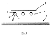
- a substrate heater comprises a substrate 1, three infrared heating elements 2 and a thermal insulation device 3.
- the infrared heating elements 2 are thermally decoupled between the substrate 1 and the thermal insulation device 3 at a distance of about 2 cm.
- the thermal insulation device 3 for thermal insulation of the vacuum chamber consists of a package of three successively arranged reflective radiant panels.
- the sheets have an emission coefficient of ⁇ ⁇ 0.1. By using these non-thermally contacting sheets in a vacuum, an exchange of thermal energy can only take place via thermal radiation.
- the heat radiation of the sheets is relatively low because of their low emission coefficient. If e.g. the first sheet of the thermal insulation device 3 heated by the infrared heaters 2 to about 500 ° C, the second radiation plate only has a temperature of about 400 ° C, while the chamber wall opposite last sheet only has a temperature of 300 ° C. ,
- the tungsten heating wires 4 are each enveloped by a compacted quartz sand filling 7 and jacket tubes 5 made of Inconel®.
- the jacket tubes 5 are electrically insulated from the respective Wolfram investigatingdrähten 4.
- the jacket tubes 5 are provided on their facing the substrate 1 surface with a TiO 2 layer 6 as an infrared-emitting layer.
- the TiO 2 layer 6 has a thickness of 100 ⁇ m and was applied to the jacket tube 5 by means of plasma spraying. However, the coating may also be applied by sputtering, in which case thinner layers in the range of 10 nm and more are preferred.
- jacket temperatures of about 600 ° C are required for substrate temperatures of more than 400 ° C.
- these jacket temperatures are far from the melting point of the metal shell 5 (about 1100 ° C). The jacket temperature can thus be lowered to uncritical temperatures with the substrate heater according to the invention and the losses in the case of substrate heating can be reduced by means of thermal radiation.
Landscapes
- Engineering & Computer Science (AREA)
- Physics & Mathematics (AREA)
- General Physics & Mathematics (AREA)
- Toxicology (AREA)
- High Energy & Nuclear Physics (AREA)
- Condensed Matter Physics & Semiconductors (AREA)
- Health & Medical Sciences (AREA)
- Manufacturing & Machinery (AREA)
- Computer Hardware Design (AREA)
- Microelectronics & Electronic Packaging (AREA)
- Power Engineering (AREA)
- Physical Vapour Deposition (AREA)
- Resistance Heating (AREA)
- Application Of Or Painting With Fluid Materials (AREA)
Priority Applications (8)
| Application Number | Priority Date | Filing Date | Title |
|---|---|---|---|
| EP04017775A EP1631121B1 (fr) | 2004-07-27 | 2004-07-27 | Elément chauffant infrarouge et chambre à vide avec chauffage de substrat, notemment pour installations de revêtement sous vide |
| DE502004005277T DE502004005277D1 (de) | 2004-07-27 | 2004-07-27 | Infrarotheizelement und Vakuumkammer mit Substratheizung, insbesondere für Vakuumbeschichtungsanlagen |
| AT04017775T ATE376343T1 (de) | 2004-07-27 | 2004-07-27 | Infrarotheizelement und vakuumkammer mit substratheizung, insbesondere für vakuumbeschichtungsanlagen |
| ES04017775T ES2294406T3 (es) | 2004-07-27 | 2004-07-27 | Elemento de calentamiento infrarrojo y camara de vacio con calentamiento de sustrato especialmente para instalaciones de revestimiento a vacio. |
| TW094111982A TWI299515B (en) | 2004-07-27 | 2005-04-15 | An infrared heating element and a substrate heater type vacuum chamber, particularly for vacuum coating facilities |
| JP2005131831A JP2006041478A (ja) | 2004-07-27 | 2005-04-28 | 赤外線加熱要素と、特に真空コーティング設備用の基板加熱器型真空チャンバ |
| KR1020050042402A KR100679679B1 (ko) | 2004-07-27 | 2005-05-20 | 적외선 가열기구 및 기지 가열기 형식의 진공 챔버 |
| CNA2005100871376A CN1738494A (zh) | 2004-07-27 | 2005-07-27 | 一种红外加热元件及衬底加热器型真空腔 |
Applications Claiming Priority (1)
| Application Number | Priority Date | Filing Date | Title |
|---|---|---|---|
| EP04017775A EP1631121B1 (fr) | 2004-07-27 | 2004-07-27 | Elément chauffant infrarouge et chambre à vide avec chauffage de substrat, notemment pour installations de revêtement sous vide |
Publications (2)
| Publication Number | Publication Date |
|---|---|
| EP1631121A1 true EP1631121A1 (fr) | 2006-03-01 |
| EP1631121B1 EP1631121B1 (fr) | 2007-10-17 |
Family
ID=34925954
Family Applications (1)
| Application Number | Title | Priority Date | Filing Date |
|---|---|---|---|
| EP04017775A Not-in-force EP1631121B1 (fr) | 2004-07-27 | 2004-07-27 | Elément chauffant infrarouge et chambre à vide avec chauffage de substrat, notemment pour installations de revêtement sous vide |
Country Status (8)
| Country | Link |
|---|---|
| EP (1) | EP1631121B1 (fr) |
| JP (1) | JP2006041478A (fr) |
| KR (1) | KR100679679B1 (fr) |
| CN (1) | CN1738494A (fr) |
| AT (1) | ATE376343T1 (fr) |
| DE (1) | DE502004005277D1 (fr) |
| ES (1) | ES2294406T3 (fr) |
| TW (1) | TWI299515B (fr) |
Families Citing this family (2)
| Publication number | Priority date | Publication date | Assignee | Title |
|---|---|---|---|---|
| JP2007218805A (ja) | 2006-02-17 | 2007-08-30 | Advantest Corp | 測定装置および測定方法 |
| TWI494174B (zh) * | 2012-05-16 | 2015-08-01 | Kern Energy Entpr Co Ltd | 基板表面處理設備 |
Citations (5)
| Publication number | Priority date | Publication date | Assignee | Title |
|---|---|---|---|---|
| US3562006A (en) * | 1967-05-24 | 1971-02-09 | Us Army | Infrared source |
| JPS63281181A (ja) * | 1987-05-14 | 1988-11-17 | Canon Inc | 定着装置 |
| JPH06134040A (ja) * | 1992-10-22 | 1994-05-17 | Katsuyoshi Inai | 遠赤外線放射電熱ヒータ |
| US5350927A (en) * | 1992-06-17 | 1994-09-27 | Mitech Scientific Corp. | Radiation emitting ceramic materials and devices containing same |
| US5915072A (en) * | 1997-04-30 | 1999-06-22 | Hill-Rom, Inc. | Infrared heater apparatus |
-
2004
- 2004-07-27 AT AT04017775T patent/ATE376343T1/de not_active IP Right Cessation
- 2004-07-27 ES ES04017775T patent/ES2294406T3/es active Active
- 2004-07-27 EP EP04017775A patent/EP1631121B1/fr not_active Not-in-force
- 2004-07-27 DE DE502004005277T patent/DE502004005277D1/de not_active Expired - Fee Related
-
2005
- 2005-04-15 TW TW094111982A patent/TWI299515B/zh active
- 2005-04-28 JP JP2005131831A patent/JP2006041478A/ja active Pending
- 2005-05-20 KR KR1020050042402A patent/KR100679679B1/ko not_active IP Right Cessation
- 2005-07-27 CN CNA2005100871376A patent/CN1738494A/zh active Pending
Patent Citations (5)
| Publication number | Priority date | Publication date | Assignee | Title |
|---|---|---|---|---|
| US3562006A (en) * | 1967-05-24 | 1971-02-09 | Us Army | Infrared source |
| JPS63281181A (ja) * | 1987-05-14 | 1988-11-17 | Canon Inc | 定着装置 |
| US5350927A (en) * | 1992-06-17 | 1994-09-27 | Mitech Scientific Corp. | Radiation emitting ceramic materials and devices containing same |
| JPH06134040A (ja) * | 1992-10-22 | 1994-05-17 | Katsuyoshi Inai | 遠赤外線放射電熱ヒータ |
| US5915072A (en) * | 1997-04-30 | 1999-06-22 | Hill-Rom, Inc. | Infrared heater apparatus |
Non-Patent Citations (3)
| Title |
|---|
| PATENT ABSTRACTS OF JAPAN vol. 013, no. 102 (P - 841) 10 March 1989 (1989-03-10) * |
| PATENT ABSTRACTS OF JAPAN vol. 013, no. 280 (E - 779) 27 June 1989 (1989-06-27) * |
| PATENT ABSTRACTS OF JAPAN vol. 018, no. 433 (C - 1237) 12 August 1994 (1994-08-12) * |
Also Published As
| Publication number | Publication date |
|---|---|
| EP1631121B1 (fr) | 2007-10-17 |
| KR100679679B1 (ko) | 2007-02-06 |
| CN1738494A (zh) | 2006-02-22 |
| KR20060048041A (ko) | 2006-05-18 |
| TWI299515B (en) | 2008-08-01 |
| TW200605181A (en) | 2006-02-01 |
| ATE376343T1 (de) | 2007-11-15 |
| JP2006041478A (ja) | 2006-02-09 |
| ES2294406T3 (es) | 2008-04-01 |
| DE502004005277D1 (de) | 2007-11-29 |
Similar Documents
| Publication | Publication Date | Title |
|---|---|---|
| DE10162276C5 (de) | Rohrförmiger Durchlauferhitzer und Heizplatte sowie Verfahren zu deren Herstellung | |
| DE19544525C2 (de) | Verfahren zur Wärmebehandlung eines Halbleiterkörpers | |
| EP3516925A1 (fr) | Radiateurs surfaciques à infrarouge | |
| WO2006125507A1 (fr) | Chauffage par rayonnement pour chauffer le materiau de construction dans un dispositif de frittage laser | |
| WO2010115558A1 (fr) | Procédé et système pour produire un objet revêtu par traitement thermique | |
| EP2529406B1 (fr) | Procédé de fabrication d'un objet revêtu par gravure de texture | |
| DE19938808A1 (de) | Verfahren und Vorrichtung zum homogenen Erwärmen von Gläsern und/oder Glaskeramiken mit Hilfe von IR-Strahlung | |
| EP3516680A1 (fr) | Émetteur de rayonnement infrarouge | |
| EP1277238B1 (fr) | Dispositif et procédé pour le recuit simultané de plusieurs produits fabriqués | |
| WO2000056675A1 (fr) | Procede et dispositif pour chauffer de maniere homogene des verres et/ou des vitroceramiques par rayons infrarouges | |
| DE3210676A1 (de) | Quarzlampen-strahlungsofen | |
| DE102018125304A1 (de) | Heizeinrichtung mit einem Infrarot-Flächenstrahler | |
| JP6820928B2 (ja) | Low−Eガラスの熱処理方法及びシステム | |
| DE4202944C2 (de) | Verfahren und Vorrichtung zum Erwärmen eines Materials | |
| EP1631121B1 (fr) | Elément chauffant infrarouge et chambre à vide avec chauffage de substrat, notemment pour installations de revêtement sous vide | |
| EP3436271B1 (fr) | Imprimante avec une unité de séchage à infrarouge | |
| EP2537175A1 (fr) | Dispositif de traitement thermique de substrats | |
| DE2710483A1 (de) | Verfahren zum niederschlagen einer schicht | |
| DE102016120536A1 (de) | Infrarotstrahler | |
| DE102017223592B4 (de) | System zur elektrisch entkoppelten, homogenen Temperierung einer Elektrode mittels Wärmeleitrohren sowie Bearbeitungsanlage mit einem solchen System | |
| DE1521175A1 (de) | Vorrichtung zur Verdampfung von Stoffen im Vakuum | |
| EP2026628B1 (fr) | Dispositif destiné au réchauffement d'une feuille | |
| DE102004046033B4 (de) | Energie sparende Heizeinrichtung | |
| WO2002024589A1 (fr) | Dispositif et procede pour assurer la relaxation de contraintes dans du verre, notamment au niveau de l'embase du col d'un cone de televiseur | |
| DE102012106325A1 (de) | Vorrichtung und Verfahren zum Aufheizen und Abkühlen einer Substratbehandlungsanlage |
Legal Events
| Date | Code | Title | Description |
|---|---|---|---|
| PUAI | Public reference made under article 153(3) epc to a published international application that has entered the european phase |
Free format text: ORIGINAL CODE: 0009012 |
|
| 17P | Request for examination filed |
Effective date: 20040727 |
|
| AK | Designated contracting states |
Kind code of ref document: A1 Designated state(s): AT BE BG CH CY CZ DE DK EE ES FI FR GB GR HU IE IT LI LU MC NL PL PT RO SE SI SK TR |
|
| AX | Request for extension of the european patent |
Extension state: AL HR LT LV MK |
|
| AKX | Designation fees paid |
Designated state(s): AT BE BG CH CY CZ DE DK EE ES FI FR GB GR HU IE IT LI LU MC NL PL PT RO SE SI SK TR |
|
| RAP1 | Party data changed (applicant data changed or rights of an application transferred) |
Owner name: APPLIED MATERIALS GMBH & CO. KG |
|
| GRAP | Despatch of communication of intention to grant a patent |
Free format text: ORIGINAL CODE: EPIDOSNIGR1 |
|
| GRAS | Grant fee paid |
Free format text: ORIGINAL CODE: EPIDOSNIGR3 |
|
| GRAA | (expected) grant |
Free format text: ORIGINAL CODE: 0009210 |
|
| AK | Designated contracting states |
Kind code of ref document: B1 Designated state(s): AT BE BG CH CY CZ DE DK EE ES FI FR GB GR HU IE IT LI LU MC NL PL PT RO SE SI SK TR |
|
| REG | Reference to a national code |
Ref country code: GB Ref legal event code: FG4D Free format text: NOT ENGLISH |
|
| REG | Reference to a national code |
Ref country code: CH Ref legal event code: EP |
|
| REG | Reference to a national code |
Ref country code: IE Ref legal event code: FG4D Free format text: LANGUAGE OF EP DOCUMENT: GERMAN |
|
| REF | Corresponds to: |
Ref document number: 502004005277 Country of ref document: DE Date of ref document: 20071129 Kind code of ref document: P |
|
| REG | Reference to a national code |
Ref country code: CH Ref legal event code: NV Representative=s name: TROESCH SCHEIDEGGER WERNER AG |
|
| ET | Fr: translation filed | ||
| REG | Reference to a national code |
Ref country code: GR Ref legal event code: EP Ref document number: 20070403809 Country of ref document: GR |
|
| REG | Reference to a national code |
Ref country code: ES Ref legal event code: FG2A Ref document number: 2294406 Country of ref document: ES Kind code of ref document: T3 |
|
| PG25 | Lapsed in a contracting state [announced via postgrant information from national office to epo] |
Ref country code: SE Free format text: LAPSE BECAUSE OF FAILURE TO SUBMIT A TRANSLATION OF THE DESCRIPTION OR TO PAY THE FEE WITHIN THE PRESCRIBED TIME-LIMIT Effective date: 20080117 |
|
| GBV | Gb: ep patent (uk) treated as always having been void in accordance with gb section 77(7)/1977 [no translation filed] | ||
| PG25 | Lapsed in a contracting state [announced via postgrant information from national office to epo] |
Ref country code: SI Free format text: LAPSE BECAUSE OF FAILURE TO SUBMIT A TRANSLATION OF THE DESCRIPTION OR TO PAY THE FEE WITHIN THE PRESCRIBED TIME-LIMIT Effective date: 20071017 Ref country code: PL Free format text: LAPSE BECAUSE OF FAILURE TO SUBMIT A TRANSLATION OF THE DESCRIPTION OR TO PAY THE FEE WITHIN THE PRESCRIBED TIME-LIMIT Effective date: 20071017 Ref country code: BG Free format text: LAPSE BECAUSE OF FAILURE TO SUBMIT A TRANSLATION OF THE DESCRIPTION OR TO PAY THE FEE WITHIN THE PRESCRIBED TIME-LIMIT Effective date: 20080117 Ref country code: PT Free format text: LAPSE BECAUSE OF FAILURE TO SUBMIT A TRANSLATION OF THE DESCRIPTION OR TO PAY THE FEE WITHIN THE PRESCRIBED TIME-LIMIT Effective date: 20080317 |
|
| REG | Reference to a national code |
Ref country code: IE Ref legal event code: FD4D |
|
| PG25 | Lapsed in a contracting state [announced via postgrant information from national office to epo] |
Ref country code: DK Free format text: LAPSE BECAUSE OF FAILURE TO SUBMIT A TRANSLATION OF THE DESCRIPTION OR TO PAY THE FEE WITHIN THE PRESCRIBED TIME-LIMIT Effective date: 20071017 Ref country code: CZ Free format text: LAPSE BECAUSE OF FAILURE TO SUBMIT A TRANSLATION OF THE DESCRIPTION OR TO PAY THE FEE WITHIN THE PRESCRIBED TIME-LIMIT Effective date: 20071017 |
|
| PGFP | Annual fee paid to national office [announced via postgrant information from national office to epo] |
Ref country code: CH Payment date: 20080620 Year of fee payment: 5 |
|
| PLBE | No opposition filed within time limit |
Free format text: ORIGINAL CODE: 0009261 |
|
| STAA | Information on the status of an ep patent application or granted ep patent |
Free format text: STATUS: NO OPPOSITION FILED WITHIN TIME LIMIT |
|
| PG25 | Lapsed in a contracting state [announced via postgrant information from national office to epo] |
Ref country code: RO Free format text: LAPSE BECAUSE OF FAILURE TO SUBMIT A TRANSLATION OF THE DESCRIPTION OR TO PAY THE FEE WITHIN THE PRESCRIBED TIME-LIMIT Effective date: 20071017 Ref country code: SK Free format text: LAPSE BECAUSE OF FAILURE TO SUBMIT A TRANSLATION OF THE DESCRIPTION OR TO PAY THE FEE WITHIN THE PRESCRIBED TIME-LIMIT Effective date: 20071017 |
|
| 26N | No opposition filed |
Effective date: 20080718 |
|
| PGFP | Annual fee paid to national office [announced via postgrant information from national office to epo] |
Ref country code: IT Payment date: 20080619 Year of fee payment: 5 |
|
| PG25 | Lapsed in a contracting state [announced via postgrant information from national office to epo] |
Ref country code: IE Free format text: LAPSE BECAUSE OF FAILURE TO SUBMIT A TRANSLATION OF THE DESCRIPTION OR TO PAY THE FEE WITHIN THE PRESCRIBED TIME-LIMIT Effective date: 20071017 |
|
| PGFP | Annual fee paid to national office [announced via postgrant information from national office to epo] |
Ref country code: DE Payment date: 20080623 Year of fee payment: 5 Ref country code: ES Payment date: 20080709 Year of fee payment: 5 |
|
| PG25 | Lapsed in a contracting state [announced via postgrant information from national office to epo] |
Ref country code: GB Free format text: LAPSE BECAUSE OF FAILURE TO SUBMIT A TRANSLATION OF THE DESCRIPTION OR TO PAY THE FEE WITHIN THE PRESCRIBED TIME-LIMIT Effective date: 20071017 |
|
| PGFP | Annual fee paid to national office [announced via postgrant information from national office to epo] |
Ref country code: FR Payment date: 20080613 Year of fee payment: 5 Ref country code: NL Payment date: 20080619 Year of fee payment: 5 |
|
| PG25 | Lapsed in a contracting state [announced via postgrant information from national office to epo] |
Ref country code: FI Free format text: LAPSE BECAUSE OF FAILURE TO SUBMIT A TRANSLATION OF THE DESCRIPTION OR TO PAY THE FEE WITHIN THE PRESCRIBED TIME-LIMIT Effective date: 20071017 |
|
| PG25 | Lapsed in a contracting state [announced via postgrant information from national office to epo] |
Ref country code: MC Free format text: LAPSE BECAUSE OF NON-PAYMENT OF DUE FEES Effective date: 20080731 |
|
| PG25 | Lapsed in a contracting state [announced via postgrant information from national office to epo] |
Ref country code: EE Free format text: LAPSE BECAUSE OF FAILURE TO SUBMIT A TRANSLATION OF THE DESCRIPTION OR TO PAY THE FEE WITHIN THE PRESCRIBED TIME-LIMIT Effective date: 20071017 |
|
| PGFP | Annual fee paid to national office [announced via postgrant information from national office to epo] |
Ref country code: GR Payment date: 20080620 Year of fee payment: 5 |
|
| PG25 | Lapsed in a contracting state [announced via postgrant information from national office to epo] |
Ref country code: CY Free format text: LAPSE BECAUSE OF FAILURE TO SUBMIT A TRANSLATION OF THE DESCRIPTION OR TO PAY THE FEE WITHIN THE PRESCRIBED TIME-LIMIT Effective date: 20071017 |
|
| PG25 | Lapsed in a contracting state [announced via postgrant information from national office to epo] |
Ref country code: AT Free format text: LAPSE BECAUSE OF NON-PAYMENT OF DUE FEES Effective date: 20080727 |
|
| REG | Reference to a national code |
Ref country code: CH Ref legal event code: PL |
|
| NLV4 | Nl: lapsed or anulled due to non-payment of the annual fee |
Effective date: 20100201 |
|
| REG | Reference to a national code |
Ref country code: FR Ref legal event code: ST Effective date: 20100331 |
|
| PG25 | Lapsed in a contracting state [announced via postgrant information from national office to epo] |
Ref country code: CH Free format text: LAPSE BECAUSE OF NON-PAYMENT OF DUE FEES Effective date: 20090731 Ref country code: LI Free format text: LAPSE BECAUSE OF NON-PAYMENT OF DUE FEES Effective date: 20090731 Ref country code: FR Free format text: LAPSE BECAUSE OF NON-PAYMENT OF DUE FEES Effective date: 20090731 |
|
| PG25 | Lapsed in a contracting state [announced via postgrant information from national office to epo] |
Ref country code: DE Free format text: LAPSE BECAUSE OF NON-PAYMENT OF DUE FEES Effective date: 20100202 |
|
| PG25 | Lapsed in a contracting state [announced via postgrant information from national office to epo] |
Ref country code: HU Free format text: LAPSE BECAUSE OF FAILURE TO SUBMIT A TRANSLATION OF THE DESCRIPTION OR TO PAY THE FEE WITHIN THE PRESCRIBED TIME-LIMIT Effective date: 20080418 Ref country code: BE Free format text: LAPSE BECAUSE OF NON-PAYMENT OF DUE FEES Effective date: 20080731 Ref country code: LU Free format text: LAPSE BECAUSE OF NON-PAYMENT OF DUE FEES Effective date: 20080727 |
|
| PG25 | Lapsed in a contracting state [announced via postgrant information from national office to epo] |
Ref country code: TR Free format text: LAPSE BECAUSE OF FAILURE TO SUBMIT A TRANSLATION OF THE DESCRIPTION OR TO PAY THE FEE WITHIN THE PRESCRIBED TIME-LIMIT Effective date: 20071017 |
|
| REG | Reference to a national code |
Ref country code: ES Ref legal event code: FD2A Effective date: 20090728 |
|
| PG25 | Lapsed in a contracting state [announced via postgrant information from national office to epo] |
Ref country code: GR Free format text: LAPSE BECAUSE OF NON-PAYMENT OF DUE FEES Effective date: 20100204 Ref country code: ES Free format text: LAPSE BECAUSE OF NON-PAYMENT OF DUE FEES Effective date: 20090728 |
|
| PG25 | Lapsed in a contracting state [announced via postgrant information from national office to epo] |
Ref country code: IT Free format text: LAPSE BECAUSE OF NON-PAYMENT OF DUE FEES Effective date: 20090727 |
|
| PG25 | Lapsed in a contracting state [announced via postgrant information from national office to epo] |
Ref country code: NL Free format text: LAPSE BECAUSE OF NON-PAYMENT OF DUE FEES Effective date: 20100201 |