EP1631017A1 - Handover method for mobile communication systems having overlapping area - Google Patents
Handover method for mobile communication systems having overlapping area Download PDFInfo
- Publication number
- EP1631017A1 EP1631017A1 EP05017634A EP05017634A EP1631017A1 EP 1631017 A1 EP1631017 A1 EP 1631017A1 EP 05017634 A EP05017634 A EP 05017634A EP 05017634 A EP05017634 A EP 05017634A EP 1631017 A1 EP1631017 A1 EP 1631017A1
- Authority
- EP
- European Patent Office
- Prior art keywords
- handover
- mobile terminal
- layer
- access
- overlapping area
- Prior art date
- Legal status (The legal status is an assumption and is not a legal conclusion. Google has not performed a legal analysis and makes no representation as to the accuracy of the status listed.)
- Granted
Links
Images



Classifications
-
- H—ELECTRICITY
- H04—ELECTRIC COMMUNICATION TECHNIQUE
- H04W—WIRELESS COMMUNICATION NETWORKS
- H04W36/00—Hand-off or reselection arrangements
- H04W36/0005—Control or signalling for completing the hand-off
- H04W36/0011—Control or signalling for completing the hand-off for data sessions of end-to-end connection
-
- H—ELECTRICITY
- H04—ELECTRIC COMMUNICATION TECHNIQUE
- H04W—WIRELESS COMMUNICATION NETWORKS
- H04W36/00—Hand-off or reselection arrangements
- H04W36/12—Reselecting a serving backbone network switching or routing node
- H04W36/125—Reselecting a serving backbone network switching or routing node involving different types of service backbones
-
- H—ELECTRICITY
- H04—ELECTRIC COMMUNICATION TECHNIQUE
- H04W—WIRELESS COMMUNICATION NETWORKS
- H04W80/00—Wireless network protocols or protocol adaptations to wireless operation
- H04W80/04—Network layer protocols, e.g. mobile IP [Internet Protocol]
-
- H—ELECTRICITY
- H04—ELECTRIC COMMUNICATION TECHNIQUE
- H04W—WIRELESS COMMUNICATION NETWORKS
- H04W36/00—Hand-off or reselection arrangements
- H04W36/12—Reselecting a serving backbone network switching or routing node
-
- H—ELECTRICITY
- H04—ELECTRIC COMMUNICATION TECHNIQUE
- H04W—WIRELESS COMMUNICATION NETWORKS
- H04W74/00—Wireless channel access
-
- H—ELECTRICITY
- H04—ELECTRIC COMMUNICATION TECHNIQUE
- H04W—WIRELESS COMMUNICATION NETWORKS
- H04W80/00—Wireless network protocols or protocol adaptations to wireless operation
Definitions
- the present invention relates to a handover method for an IP-based next generation mobile communication system network.
- IP Internet Protocol
- Layer 3 handover (handover for routing in the IP network) is important for proper operation, as is Layer 2 handover (handover between base stations in the wireless telephone network), both of which have attracted attention in conventional wireless telephone networks.
- FIG. 1 is a view for explaining a cell group for handover in the conventional next generation mobile communication system.
- the conventional next generation mobile communication system includes an access router 1 (AR 1) 10 and an access router 2 (AR2) 11 for routing in an IP network.
- the ARs 10 and 11 include a plurality of access points (APs), each of which controls one cell.
- Each AP provides services for a mobile terminal (MT) 13 located in a cell controlled by the AP.
- MT mobile terminal
- AR areas are divided in the same manner as AP groups are divided as shown by line 100 in FIG. 1. Accordingly, L2 handover between APs and L3 handover between ARs are performed at the same time.
- each of the ARs relates to an individual network constructed by binding a plurality of cells into a cell group.
- L2 handover is performed when the MT moves in each cell group, and the L2 handover of the APs and the L3 handover between the ARs are performed at the same time when the MT moves between cell groups.
- FIG. 2 is a flowchart showing the handover process in the conventional next generation mobile communication system.
- step 201 it is determined whether or not the mobile terminal 13 has left a predetermined AP area (step 202). Referring to FIG. 1, it is determined whether or not the MT 13 of an AP 101 has moved to another AP.
- step 203 it is determined whether or not the MT 13 has left an AR area. Referring to FIG. 1, it is determined whether or not the MT 13 of the AP 101 has moved to an AP 111 in another AR area.
- the MT 13 performs L3 handover between ARs and L2 handover between APs at the same time (step 205).
- step 204 If, however, it is determined that the MT 13 has not left the AR area in step 203 (i.e., if the MT 13 moves to another AP in the same AR area and not the AP 111 shown in FIG. 1), the L2 handover between APs is performed (step 204).
- the present invention has been made to solve the above-mentioned problems occurring in the prior art.
- An aspect of the present invention is to provide a handover method for a next generation mobile communication system having an overlapping area, that can reduce a packet drop rate and packet delay time caused by individually transmitting packets between two routers when L3 handover occurs.
- a handover method for an Internet protocol (IP)-based next generation mobile communication system including arranging at borders between access routers managing cell groups an overlapping area to which all of the neighboring access routers have access; and if a predetermined terminal enters the overlapping area, making Layer 3 handover (L3 handover) between the neighboring access routers performed with respect to the mobile terminal.
- IP Internet protocol
- a handover method for an Internet protocol (IP)-based next generation mobile communication system arranging at borders between access routers managing cell groups an overlapping area to which all of the neighboring access routers have access, the handover method including determining whether or not a predetermined mobile terminal goes into the overlapping area; starting a Layer 3 (L3) handover operation between the neighboring access routers as the mobile terminal goes into the overlapping area; if the Layer 3 handover operation between the neighboring access routers is completed, establishing a data path for the mobile terminal to pass through an access router after the Layer 3 handover; if the mobile terminal leaves a cell area including the mobile terminal , performing by the mobile terminal Layer 2 handover between cells and receiving by the mobile terminal data through a cell base station after the Layer 2 handover and an access router before the Layer 3 handover; and if the mobile terminal leaves a cell area including the mobile terminal, performing by the mobile terminal Layer 2 handover between cells and receiving by the mobile terminal data through a cell base station after the Layer 2 handover and an access router before the Layer 3 handover;
- FIG. 3 is a view for explaining an overlapping cell group in a next generation mobile communication system according to an embodiment of the present invention.
- the next generation mobile communication system includes an access router 1 (AR 1) 10 and an access router 2 (AR2) 11 for performing routing functions in the IP network.
- Each of the ARs 10 and 11 includes a plurality of access points (APs), each of which controls one cell.
- Each AP provides services for a mobile terminal (MT) 13 located in a cell controlled by the AP.
- MT mobile terminal
- an overlapping area between cells of the AR1 10 and cells of the AR2 11 is arranged at both sides of line 100 of FIG. 3 which divides the area of the AR1 10 and the area of the AR 2 11.
- access to all ARs e.g., the AR1 and the AR2
- access to at least two ARs is allowed according to the number of overlapping cell groups.
- APs in the overlapping area have interfaces for at least two ARs. Therefore, it is unnecessary to consider additional IP routing for uplink transmission, because uplink transmission can be achieved through either of the ARs.
- the L2 handover and the L3 handover are separated, such that the L3 handover may be performed in an overlapping area 300.
- the movement of the mobile terminal 13 is estimated to perform the L3 handover in the overlapping area 300.
- the L2 handover is independently performed from the L3 handover according to movement of the mobile terminal 13 between cells in the same manner as the conventional technique.
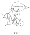
- FIG. 4 is a view for explaining handover in the next generation mobile communication system having the overlapping area according to the present invention.
- the next generation mobile communication system includes a home agent (HA) 400 for storing information regarding a position and a specific identifier (ID) of the mobile terminal, an IP backbone network 40 for IP communication, the AR 1 10 and the AR 2 11 which are connected to the IP backbone network 40, an AP 1 401 and an AP 2 402 which control cells belonging to the AR 1 10, an AP 3 403 and an AP 4 404 which control cells belonging to the AR 2 11, and the mobile terminal 13 which is moving to the AP 4 404 from the AP 1 401 through the AP 2 402 and the AP 3 403.
- HA home agent
- an overlapping area 42 in which the L3 handover is performed with respect to the AR 1 10 and the AR 2 11 exists between the AP 2 402 and the AP 3 403. In this overlapping area 42, it is possible to have access to both the AR 1 10 and the AR 2 11.
- the mobile terminal 13 When the mobile terminal 13 performs handover 41 to the AP 2 402 from the AP 1 401, since the mobile terminal 13 performs handover between APs belonging to the same AR, the mobile terminal 13 performs the L2 handover. In addition, if the mobile terminal 13 goes into the overlapping area 42 while moving to the AP 3 403 from the AP 2 402, the mobile terminal 13 performs the L3 handover.
- the L2 handover 41 between the AP 2 402 and the AP 3 403 in the overlapping area 42 is performed separately from the L3 handover.
- the AP 2 402 Since the overlapping area 42 is connected to the areas of both the AR 1 10 and the AR 2 11, the AP 2 402 having detected the movement for the mobile terminal 13 entering a corresponding sector of the AP 2 commands the L3 handover.
- the L3 handover occurs to the AR 2 11 from the AR 1 10 after the L2 handover to the AP 2 402 from the AP 1 401, and then, when the mobile terminal 13 enters the AP 3 403, the L2 handover occurs again.
- one AP is connected to at least two ARs, it is possible to solve overhead problems caused by the L3 handover simultaneously occurring with the L2 handover.
- the present invention it is possible to receive packets arriving at the AP 2 402 through the AR 1 10 without forwarding the packets to another router (e.g., AR2).
- another router e.g., AR2
- COA care-of-address
- the packets can be mapped with a previous link layer ID. Therefore, the AP can transmit the previous packets as is to the mobile terminal by adding only a few functions.
- packets to be transmitted to the mobile terminal 13 are forwarded to the AR 1 10, before the L3 handover, and forwarded to the AR 2 11 after the L3 handover.
- packets generated by the mobile terminal 13 performing handover can be routed to one of the AR 1 10 and the AR 2 11 because each AP has access to both the AR 1 10 and the AR 2 11 in the overlapping area (reference numeral 42).
- FIG. 5 is a flowchart showing the handover process in the next generation mobile communication system having the overlapping area according to an embodiment of the present invention.
- an AP having detected the movement of the mobile terminal commands the L3 handover between ARs (AR 1 ⁇ AR2) with respect to the corresponding mobile terminal, so that the L3 handover may start.
- AR 1 ⁇ AR2 ARs
- step 503 it is determined whether or not the mobile terminal left the current AP (AP 2) area (step 503). If the mobile terminal has left the AP area, the L2 handover between APs (AP 2 ⁇ AP 3) is performed independently from the L3 handover (step 509). Herein, data is transmitted to the mobile terminal from the AR 1 (because the L3 handover is not completed yet) through the AP2 (step 510).
- step 503 If the mobile terminal has not left the AP area (AP2) in step 503, data is transmitted to the mobile terminal from the AR 1 (because the L3 handover is not completed yet) through the AP 2 (step 504).
- step 504 data is transmitted to the mobile terminal from the AR 2 through the AP 2 (step 506). Thereafter, it is determined whether the mobile terminal has left the current AP (AP 2) area (step 507). If the mobile terminal has left the AP area, the L2 handover between APs (AP 2 ⁇ AP 3) is performed independently from the L3 handover (step 508). At this point, data is transmitted to the mobile terminal from the AR 2 through the AP 3 (step 512). If the mobile terminal has not left the AP area in step 507, the data transmission path (on which data is transmitted to the mobile terminal from the AR 2 through the AP 2) is maintained (step 506) until the mobile terminal leaves the AP area (step 507).
- step 511 If the L3 handover has been completed on the data transmission path in step 510(step 511), data is transmitted to the mobile terminal from the AR 2 through the AP 3 (step 512). If the L3 handover has not completed in step 511, the data transmission path (on which data are transmitted to the mobile terminal from the AR1 through the AP 3) is maintained (step 510) until the L3 handover is complete (step 511).
- L2 handover is performed when a mobile terminal moves between cells
- L3 handover is performed when a mobile terminal moves between cell groups.
- the conventional technique which allows simultaneous execution of the L2 handover and the L3 handover through the same signaling message, increases signaling message overhead, thereby increasing delay time.
- proper data transmission is not achieved until the L3 handover is completed, even after the L2 handover is completed in accordance with the execution of the L3 handover.
- the conventional technique requires a forwarding operation between routers for packets generated during the L3 handover.
- the present invention does not require the forwarding operation because it is possible to give access to access routers relating to the overlapping area in the overlapping area in which the L3 handover is performed.
- the method according to the present invention may be implemented by a computer program and stored on computer-readable recording media (CD-ROMs, RAMs, floppy disks, hard disks, magneto-optical disks, etc.).
- CD-ROMs compact discs
- RAMs random access memory
- floppy disks disks
- hard disks hard disks
- magneto-optical disks etc.
Landscapes
- Engineering & Computer Science (AREA)
- Computer Networks & Wireless Communication (AREA)
- Signal Processing (AREA)
- Mobile Radio Communication Systems (AREA)
Abstract
Description
- The present invention relates to a handover method for an IP-based next generation mobile communication system network.
- Next generation mobile communication system networks currently in development employ an integrated wireless telephone and Internet Protocol (IP) network. It is expected that the next-generation system will seamlessly integrate the wireless telephone network with the IP network.
- Accordingly, in the next generation mobile communication system networks, Layer 3 handover (handover for routing in the IP network) is important for proper operation, as is Layer 2 handover (handover between base stations in the wireless telephone network), both of which have attracted attention in conventional wireless telephone networks.
- FIG. 1 is a view for explaining a cell group for handover in the conventional next generation mobile communication system.
- The conventional next generation mobile communication system includes an access router 1 (AR 1) 10 and an access router 2 (AR2) 11 for routing in an IP network. The
ARs - In the conventional next generation mobile communication system, AR areas are divided in the same manner as AP groups are divided as shown by
line 100 in FIG. 1. Accordingly, L2 handover between APs and L3 handover between ARs are performed at the same time. - As described above, each of the ARs relates to an individual network constructed by binding a plurality of cells into a cell group. Herein, only L2 handover is performed when the MT moves in each cell group, and the L2 handover of the APs and the L3 handover between the ARs are performed at the same time when the MT moves between cell groups.
- FIG. 2 is a flowchart showing the handover process in the conventional next generation mobile communication system.
- If the
MT 13 moves (step 201), it is determined whether or not themobile terminal 13 has left a predetermined AP area (step 202). Referring to FIG. 1, it is determined whether or not theMT 13 of an AP 101 has moved to another AP. - Thereafter, if the
MT 13 has left the predetermined AP area, it is determined whether or not theMT 13 has left an AR area (step 203). Referring to FIG. 1, it is determined whether or not theMT 13 of the AP 101 has moved to an AP 111 in another AR area. - If it is determined that the
MT 13 has left the AR area in step 203 (i.e., if theMT 13 moves to theAP 111 shown in FIG. 1), theMT 13 performs L3 handover between ARs and L2 handover between APs at the same time (step 205). - If, however, it is determined that the
MT 13 has not left the AR area in step 203 (i.e., if theMT 13 moves to another AP in the same AR area and not theAP 111 shown in FIG. 1), the L2 handover between APs is performed (step 204). - When the above mobile IP technique is employed and the L2 handover and the L3 handover are performed at the same time, data is not transmitted until the L3 and L2 handover is complete since the L3 handover has signaling delay time longer than that of the L2 handover.
- Additionally, in the next generation mobile communication network, since each cell radius becomes smaller than a present cell radius according to increase of band frequency, handover occurs more frequently. In particular, if the L2 handover and the L3 handover are done repeatedly in overlapping areas where movement between areas frequently occurs, it is impossible to efficiently transmit data.
- In addition, since each handover is achieved through signaling messages over a radio link, such simultaneous support for both the L2 and L3 handover creates excessive in the signaling messages, and wasting radio resources.
- Accordingly, the present invention has been made to solve the above-mentioned problems occurring in the prior art.
- It is the object of the present invention to provide a handover method for a next generation mobile communication system having an overlapping area, that can reduce overheads of L3 handover and efficiently transmit data in an IP-based mobile communication network.
- This object is solved by the subject matter of the independent claims.
- Preferred embodiments are defined in the dependent claims.
- An aspect of the present invention is to provide a handover method for a next generation mobile communication system having an overlapping area, that can reduce a packet drop rate and packet delay time caused by individually transmitting packets between two routers when L3 handover occurs.
- To accomplish the above, there is provided a handover method for an Internet protocol (IP)-based next generation mobile communication system, the handover method including arranging at borders between access routers managing cell groups an overlapping area to which all of the neighboring access routers have access; and if a predetermined terminal enters the overlapping area, making Layer 3 handover (L3 handover) between the neighboring access routers performed with respect to the mobile terminal.
- According to another aspect of the present invention, there is provided a handover method for an Internet protocol (IP)-based next generation mobile communication system arranging at borders between access routers managing cell groups an overlapping area to which all of the neighboring access routers have access, the handover method including determining whether or not a predetermined mobile terminal goes into the overlapping area; starting a Layer 3 (L3) handover operation between the neighboring access routers as the mobile terminal goes into the overlapping area; if the Layer 3 handover operation between the neighboring access routers is completed, establishing a data path for the mobile terminal to pass through an access router after the Layer 3 handover; if the mobile terminal leaves a cell area including the mobile terminal , performing by the mobile terminal Layer 2 handover between cells and receiving by the mobile terminal data through a cell base station after the Layer 2 handover and an access router before the Layer 3 handover; and if the mobile terminal leaves a cell area including the mobile terminal, performing by the mobile terminal Layer 2 handover between cells and receiving by the mobile terminal data through a cell base station after the Layer 2 handover and an access router after the Layer 3 handover.
- The above object and other aspects, features and advantages of the present invention will be more apparent from the following detailed description taken in conjunction with the accompanying drawings, in which:
- FIG. 1 is a view for explaining a cell group for handover in a conventional next generation mobile communication system;
- FIG. 2 is a flowchart showing a handover process in a conventional next generation mobile communication system;
- FIG. 3 is a view showing an overlapping cell group in a next generation mobile communication system according to an embodiment of the present invention;
- FIG. 4 is a view for explaining handover in a next generation mobile communication system having an overlapping area according to an embodiment of the present invention; and
- FIG. 5 is a flowchart showing a handover process in a next generation mobile communication system having an overlapping area according to an embodiment of the present invention.
- Hereinafter, a preferred embodiment of the present invention will be described in detail with reference to the accompanying drawings. Note that the same or similar components in drawings are designated by the same reference numerals as far as possible although they are shown in different drawings. In the following description of the present invention, a detailed description of known functions and configurations incorporated herein will be omitted when it may make the subject matter of the present invention unclear.
- FIG. 3 is a view for explaining an overlapping cell group in a next generation mobile communication system according to an embodiment of the present invention.
- As shown in FIG. 3, the next generation mobile communication system includes an access router 1 (AR 1) 10 and an access router 2 (AR2) 11 for performing routing functions in the IP network. Each of the
ARs AR1 10 and cells of theAR2 11 is arranged at both sides ofline 100 of FIG. 3 which divides the area of theAR1 10 and the area of the AR 2 11. - As described above, according to an embodiment of the present invention, in sectors in the border of a cell group belonging to each AR, access to all ARs (e.g., the AR1 and the AR2) making the border is allowed. In certain cells, access to at least two ARs is allowed according to the number of overlapping cell groups. In addition, APs in the overlapping area have interfaces for at least two ARs. Therefore, it is unnecessary to consider additional IP routing for uplink transmission, because uplink transmission can be achieved through either of the ARs.
- In the conventional structure shown in FIG. 1, since both L2 handover and L3 handover are required for movement between cell groups, time is considerably delayed.
- According to an embodiment of the present invention, the L2 handover and the L3 handover are separated, such that the L3 handover may be performed in an
overlapping area 300. In other words, the movement of themobile terminal 13 is estimated to perform the L3 handover in theoverlapping area 300. The L2 handover is independently performed from the L3 handover according to movement of themobile terminal 13 between cells in the same manner as the conventional technique. - FIG. 4 is a view for explaining handover in the next generation mobile communication system having the overlapping area according to the present invention.
- As shown in FIG. 4, the next generation mobile communication system includes a home agent (HA) 400 for storing information regarding a position and a specific identifier (ID) of the mobile terminal, an
IP backbone network 40 for IP communication, the AR 1 10 and the AR 2 11 which are connected to theIP backbone network 40, an AP 1 401 and an AP 2 402 which control cells belonging to the AR 1 10, an AP 3 403 and an AP 4 404 which control cells belonging to the AR 2 11, and themobile terminal 13 which is moving to the AP 4 404 from the AP 1 401 through the AP 2 402 and the AP 3 403. - In addition, an
overlapping area 42 in which the L3 handover is performed with respect to the AR 1 10 and the AR 2 11 exists between the AP 2 402 and the AP 3 403. In thisoverlapping area 42, it is possible to have access to both the AR 1 10 and the AR 2 11. - Hereinafter, the handover operation where the
mobile terminal 13 is moving to the AP 4 404 from the AP 1 401 through the AP 2 402 and the AP 3 403 as shown in FIG.. 4, will be described. - When the
mobile terminal 13 performshandover 41 to the AP 2 402 from the AP 1 401, since themobile terminal 13 performs handover between APs belonging to the same AR, themobile terminal 13 performs the L2 handover. In addition, if themobile terminal 13 goes into theoverlapping area 42 while moving to the AP 3 403 from the AP 2 402, themobile terminal 13 performs the L3 handover. - At this time, the
L2 handover 41 between the AP 2 402 and the AP 3 403 in theoverlapping area 42 is performed separately from the L3 handover. - Since the
overlapping area 42 is connected to the areas of both the AR 1 10 and the AR 2 11, the AP 2 402 having detected the movement for themobile terminal 13 entering a corresponding sector of the AP 2 commands the L3 handover. In other words, the L3 handover occurs to the AR 2 11 from the AR 1 10 after the L2 handover to the AP 2 402 from the AP 1 401, and then, when themobile terminal 13 enters the AP 3 403, the L2 handover occurs again. In this case, since one AP is connected to at least two ARs, it is possible to solve overhead problems caused by the L3 handover simultaneously occurring with the L2 handover. - In addition, in the conventional technique without overlap of cell groups, a scheme of forwarding packets to a new AP from a previous AP has to be considered because the mobile terminal has to receive packets (generated during handover and remaining in queues instead of being served) from mutually different ARs.
- However, according to the present invention, it is possible to receive packets arriving at the AP 2 402 through the AR 1 10 without forwarding the packets to another router (e.g., AR2). Although a care-of-address (COA) of the packets changes in the IP layer, the packets can be mapped with a previous link layer ID. Therefore, the AP can transmit the previous packets as is to the mobile terminal by adding only a few functions.
- Hereinafter, the handover process discussed above will be described in chronological sequence. Since the
HA 400 is bound to one path, packets to be transmitted to themobile terminal 13, are forwarded to the AR 1 10, before the L3 handover, and forwarded to the AR 2 11 after the L3 handover. Herein, it is enough to deliver all packets received during the L3 handover to the APs (AP2 or AP3). In addition, packets generated by themobile terminal 13 performing handover can be routed to one of the AR 1 10 and the AR 2 11 because each AP has access to both the AR 1 10 and the AR 2 11 in the overlapping area (reference numeral 42). - FIG. 5 is a flowchart showing the handover process in the next generation mobile communication system having the overlapping area according to an embodiment of the present invention.
- It is assumed that the mobile terminal belongs to the AR 1 and the AP 2 and is moving to the AR 2 and the AP 3. In this situation, data is delivered to the mobile terminal from the AR 1 through the AP 2.
- If the mobile terminal moves to the overlapping area (step 501), an AP having detected the movement of the mobile terminal commands the L3 handover between ARs (AR 1 → AR2) with respect to the corresponding mobile terminal, so that the L3 handover may start. Although this shows a case in which an AP detects the mobile terminal movement to allow the L3 handover, it may be set in such a manner that the mobile terminal detects the movement through a pilot signal, and then, the L3 handover is performed.
- Then, it is determined whether or not the mobile terminal left the current AP (AP 2) area (step 503). If the mobile terminal has left the AP area, the L2 handover between APs (AP 2 → AP 3) is performed independently from the L3 handover (step 509). Herein, data is transmitted to the mobile terminal from the AR 1 (because the L3 handover is not completed yet) through the AP2 (step 510).
- If the mobile terminal has not left the AP area (AP2) in
step 503, data is transmitted to the mobile terminal from the AR 1 (because the L3 handover is not completed yet) through the AP 2 (step 504). - If the L3 handover has been completed on the data transmission path in
step 504, data is transmitted to the mobile terminal from the AR 2 through the AP 2 (step 506). Thereafter, it is determined whether the mobile terminal has left the current AP (AP 2) area (step 507). If the mobile terminal has left the AP area, the L2 handover between APs (AP 2 → AP 3) is performed independently from the L3 handover (step 508). At this point, data is transmitted to the mobile terminal from the AR 2 through the AP 3 (step 512). If the mobile terminal has not left the AP area instep 507, the data transmission path (on which data is transmitted to the mobile terminal from the AR 2 through the AP 2) is maintained (step 506) until the mobile terminal leaves the AP area (step 507). - If the L3 handover has been completed on the data transmission path in step 510(step 511), data is transmitted to the mobile terminal from the AR 2 through the AP 3 (step 512). If the L3 handover has not completed in
step 511, the data transmission path (on which data are transmitted to the mobile terminal from the AR1 through the AP 3) is maintained (step 510) until the L3 handover is complete (step 511). - As described above, when handover is performed in the next generation mobile communication system having an overlapping area according to an embodiment of the present invention, L2 handover is performed when a mobile terminal moves between cells, and L3 handover is performed when a mobile terminal moves between cell groups. In contrast, the conventional technique, which allows simultaneous execution of the L2 handover and the L3 handover through the same signaling message, increases signaling message overhead, thereby increasing delay time. In addition, proper data transmission is not achieved until the L3 handover is completed, even after the L2 handover is completed in accordance with the execution of the L3 handover. In addition, the conventional technique requires a forwarding operation between routers for packets generated during the L3 handover. However, the present invention does not require the forwarding operation because it is possible to give access to access routers relating to the overlapping area in the overlapping area in which the L3 handover is performed.
- As described above, according to the present invention, since L3 handover occurs in an overlapping area formed by overlapping cell groups, it is possible to reduce delay time due to L3 handover between cells.
- In addition, since it is unnecessary to individually transmit packets to two routers when L3 handover occurs, it is possible to reduce a packet drop rate and packet delay time.
- As described above, the method according to the present invention may be implemented by a computer program and stored on computer-readable recording media (CD-ROMs, RAMs, floppy disks, hard disks, magneto-optical disks, etc.).
- While the invention has been shown and described with reference to certain preferred embodiments thereof, it will be understood by those skilled in the art that various changes in form and details may be made therein without departing from the scope of the invention. Consequently, the scope of the invention should not be limited to the embodiments, but should be defined by the appended claims.
Claims (11)
- A handover method for an Internet protocol, IP, -based next generation mobile communication system, the handover method comprising the steps of:arranging at borders between access routers managing cell groups, an overlapping area to which all of the neighboring access routers have access; andif a predetermined terminal enters the overlapping area, performing Layer 3 handover, L3 handover, between the neighboring access routers with respect to the mobile terminal.
- The handover method as claimed in claim 1, wherein the mobile terminal independently performs Layer 2 handover, L2 hand over, according to movement between cells from execution of the Layer 3 handover.
- The handover method as claimed in claim 1 or 2, wherein, without a forwarding operation for packets generated during the Layer 3, the neighboring access routers have access to the mobile terminal and deliver the packets to the mobile terminal.
- The handover method as claimed in one of claims 1 to 3, wherein, in the step of performing the Layer 3 handover, the mobile terminal detects a pilot signal and determines movement according to the pilot signal.
- The handover method as claimed in one of claims 1 to 3, wherein, in the step of performing the Layer 3 handover, a base station of a cell including the mobile terminal detects movement of the mobile terminal.
- A handover method for an Internet protocol, IP, -based next generation mobile communication system arranging in borders between access routers managing cell groups an overlapping area to which all of the neighboring access routers have access, the handover method comprising the steps of:1) determining whether a predetermined mobile terminal goes into the overlapping area;2) starting a Layer 3, L3, handover operation between the neighboring access routers as the mobile terminal goes into the overlapping area;3) if the Layer 3 handover operation between the neighboring access routers is completed, establishing a data path for the mobile terminal to pass through an access router after the Layer 3 handover;4) if the mobile terminal leaves a cell area including the mobile terminal in steps 2) and 3), performing Layer 2 handover in the mobile terminal between cells and data through a cell base station to the mobile terminal after the Layer 2 handover and through an access router to the mobile terminal before the Layer 3 handover; and5) if the mobile terminal leaves the cell area including the mobile terminal after step 3), performing the Layer 2 handover in the mobile terminal between cells and receiving data through the cell base station to the mobile terminal after the Layer 2 handover and through an access router to the mobile terminal after the Layer 3 handover.
- The handover method as claimed in claim 6, wherein the mobile terminal has a path to both a cell base station before the Layer 2 handover and to an access router before the Layer 3 handover as a data path in steps 1) and 2).
- The handover method as claimed in claim 6 or 7, wherein base stations of cells including the overlapping area have access to the overlapping access routers.
- The handover method as claimed in one of claims 6 to 8, wherein, without a forwarding operation for packets generated during the Layer 3 handover between the neighboring access routers, the neighboring access routers have access to the mobile terminal and deliver the packets to the mobile terminal.
- The handover method as claimed in one of claims 6 to 9, wherein, in step 2), the mobile terminal detects a pilot signal and determines movement according to the pilot signal.
- The handover method as claimed in one of claims 6 to 9, wherein, in step 2), a base station of a cell including the mobile terminal determines movement of the mobile terminal.
Applications Claiming Priority (1)
| Application Number | Priority Date | Filing Date | Title |
|---|---|---|---|
| KR1020040068152A KR100678125B1 (en) | 2004-08-27 | 2004-08-27 | Handover Method in Next Generation Mobile Communication Systems with Overlap Area |
Publications (2)
| Publication Number | Publication Date |
|---|---|
| EP1631017A1 true EP1631017A1 (en) | 2006-03-01 |
| EP1631017B1 EP1631017B1 (en) | 2008-05-21 |
Family
ID=36605927
Family Applications (1)
| Application Number | Title | Priority Date | Filing Date |
|---|---|---|---|
| EP05017634A Expired - Lifetime EP1631017B1 (en) | 2004-08-27 | 2005-08-12 | Handover method for mobile communication systems having overlapping area |
Country Status (5)
| Country | Link |
|---|---|
| US (1) | US7353029B2 (en) |
| EP (1) | EP1631017B1 (en) |
| KR (1) | KR100678125B1 (en) |
| CN (1) | CN1750710B (en) |
| DE (1) | DE602005006915D1 (en) |
Cited By (2)
| Publication number | Priority date | Publication date | Assignee | Title |
|---|---|---|---|---|
| CN100405871C (en) * | 2006-04-30 | 2008-07-23 | 中国科学院计算技术研究所 | A Layer 3 Mobile Handover Implementation Method Based on Layer 2 Prediction and Triggering |
| CN100593929C (en) * | 2007-08-21 | 2010-03-10 | 中国科学院计算技术研究所 | A Mobile Handoff Method in Wireless Packet Network |
Families Citing this family (5)
| Publication number | Priority date | Publication date | Assignee | Title |
|---|---|---|---|---|
| KR100636318B1 (en) * | 2004-09-07 | 2006-10-18 | 삼성전자주식회사 | Address Ownership Authentication Method and System Using the COA Binding Protocol |
| US20060126563A1 (en) * | 2004-12-14 | 2006-06-15 | Sungsoo Kang | System and method of processing hand-off of mobile terminal |
| JP5029534B2 (en) * | 2008-08-15 | 2012-09-19 | 日本電気株式会社 | Wireless communication system, mobility management method, management apparatus, and base station apparatus |
| CN102612069B (en) * | 2011-01-24 | 2016-02-10 | 中兴通讯股份有限公司 | Based on the method that in the mobile communication system of IP carrying and system small area switches |
| CN112449380B (en) * | 2019-08-28 | 2024-08-23 | 深圳市优克联新技术有限公司 | Method, device, base station and storage medium for switching control |
Citations (4)
| Publication number | Priority date | Publication date | Assignee | Title |
|---|---|---|---|---|
| US20020141360A1 (en) * | 2001-04-02 | 2002-10-03 | Shinichi Baba | Soft handoff in IP-based CDMA networks by IP encapsulation |
| US20020168980A1 (en) * | 2001-05-11 | 2002-11-14 | Gwon Youngjune L. | Aggregation point prediction matching for coherent layer three signaling and fast IP mobility triggering |
| US20030104814A1 (en) * | 2001-11-30 | 2003-06-05 | Docomo Communications Laboratories Usa | Low latency mobile initiated tunneling handoff |
| US20030125027A1 (en) * | 2001-11-30 | 2003-07-03 | Docomo Communications Laboratories Usa Inc. | Low latency mobile initiated tunneling handoff |
Family Cites Families (12)
| Publication number | Priority date | Publication date | Assignee | Title |
|---|---|---|---|---|
| FI98976C (en) | 1994-07-11 | 1997-09-10 | Nokia Telecommunications Oy | Method for performing handover and cellular radio system |
| US6038449A (en) * | 1996-11-20 | 2000-03-14 | Telefonaktiebolaget L M Ericsson | Method and apparatus for inter-exchange hand-off taking into account the service capabilities of the candidate cell |
| GB9910115D0 (en) * | 1999-04-30 | 1999-06-30 | Nokia Telecommunications Oy | Handover in a communication system |
| US20020131386A1 (en) * | 2001-01-26 | 2002-09-19 | Docomo Communications Laboratories Usa, Inc. | Mobility prediction in wireless, mobile access digital networks |
| US7313628B2 (en) * | 2001-06-28 | 2007-12-25 | Nokia, Inc. | Protocol to determine optimal target access routers for seamless IP-level handover |
| US7532596B2 (en) * | 2002-04-26 | 2009-05-12 | Nokia Corporation | Optimized information transfer associated with relocation of an IP session in a mobile communications system |
| US7349390B2 (en) * | 2002-05-28 | 2008-03-25 | Ntt Docomo, Inc. | Packet transmission method and communication system |
| KR100526408B1 (en) * | 2002-10-07 | 2005-11-08 | (주)아이엠넷피아 | Method for fast-Handover using fast release message in based wireless LAN |
| US20040085957A1 (en) * | 2002-11-01 | 2004-05-06 | Sanjeev Verma | Apparatus and method for providing IP connectivity to mobile nodes during handover |
| JP4242666B2 (en) * | 2003-02-26 | 2009-03-25 | モトローラ・インコーポレイテッド | Wireless packet communication method and wireless packet communication system |
| US7069002B2 (en) * | 2003-06-30 | 2006-06-27 | Lucent Technologies Inc. | Message waiting indication operable to overcome a border condition between mobile switching centers |
| US7769378B2 (en) * | 2003-08-26 | 2010-08-03 | Motorola, Inc. | System and method to improve WLAN handover behavior at entry/exit points |
-
2004
- 2004-08-27 KR KR1020040068152A patent/KR100678125B1/en not_active Expired - Fee Related
-
2005
- 2005-07-08 US US11/177,037 patent/US7353029B2/en not_active Expired - Fee Related
- 2005-08-12 DE DE602005006915T patent/DE602005006915D1/en not_active Expired - Lifetime
- 2005-08-12 EP EP05017634A patent/EP1631017B1/en not_active Expired - Lifetime
- 2005-08-15 CN CN2005100919750A patent/CN1750710B/en not_active Expired - Fee Related
Patent Citations (4)
| Publication number | Priority date | Publication date | Assignee | Title |
|---|---|---|---|---|
| US20020141360A1 (en) * | 2001-04-02 | 2002-10-03 | Shinichi Baba | Soft handoff in IP-based CDMA networks by IP encapsulation |
| US20020168980A1 (en) * | 2001-05-11 | 2002-11-14 | Gwon Youngjune L. | Aggregation point prediction matching for coherent layer three signaling and fast IP mobility triggering |
| US20030104814A1 (en) * | 2001-11-30 | 2003-06-05 | Docomo Communications Laboratories Usa | Low latency mobile initiated tunneling handoff |
| US20030125027A1 (en) * | 2001-11-30 | 2003-07-03 | Docomo Communications Laboratories Usa Inc. | Low latency mobile initiated tunneling handoff |
Cited By (2)
| Publication number | Priority date | Publication date | Assignee | Title |
|---|---|---|---|---|
| CN100405871C (en) * | 2006-04-30 | 2008-07-23 | 中国科学院计算技术研究所 | A Layer 3 Mobile Handover Implementation Method Based on Layer 2 Prediction and Triggering |
| CN100593929C (en) * | 2007-08-21 | 2010-03-10 | 中国科学院计算技术研究所 | A Mobile Handoff Method in Wireless Packet Network |
Also Published As
| Publication number | Publication date |
|---|---|
| CN1750710A (en) | 2006-03-22 |
| DE602005006915D1 (en) | 2008-07-03 |
| US20060046722A1 (en) | 2006-03-02 |
| US7353029B2 (en) | 2008-04-01 |
| EP1631017B1 (en) | 2008-05-21 |
| KR100678125B1 (en) | 2007-02-02 |
| CN1750710B (en) | 2010-12-08 |
| KR20060019449A (en) | 2006-03-03 |
Similar Documents
| Publication | Publication Date | Title |
|---|---|---|
| US7068624B1 (en) | Wireless router and method for processing traffic in a wireless communications network | |
| EP1928133B1 (en) | Method of transmitting data in handover between base stations in wireless communication system | |
| KR101073621B1 (en) | Access network broadcast control-signaling channel | |
| US7065359B2 (en) | System and method for switching between base stations in a wireless communications system | |
| US7623863B2 (en) | System and method for adjusting connection parameters in a wireless network | |
| EP2914035B1 (en) | Base station handover method and system for communications system | |
| KR100600603B1 (en) | Recording medium storing handover method and method execution program for preventing packet loss in portable internet network | |
| KR101243730B1 (en) | Fast synchronised transparent handover method and system | |
| WO2000038465A1 (en) | Method and system for intersystem soft handoff | |
| WO2001099457A1 (en) | A method for performing a mobile user terminal route update in a telecommunication network operated based on the internet protocol | |
| US10433232B2 (en) | Internet protocol address preservation in mobile operator networks | |
| EP1983795A1 (en) | Method of performing vertical handover between different wireless networks | |
| Chekkouri et al. | Connected vehicles in an intelligent transport system | |
| EP1631017A1 (en) | Handover method for mobile communication systems having overlapping area | |
| KR101164807B1 (en) | A wireless communications system employing a network active set formed from base stations operable as primary and secondary agents | |
| US8311010B1 (en) | Data integrity negotiation schemes in wireless communication systems | |
| CN101909316B (en) | Operation maintenance method and system | |
| US7133385B2 (en) | Network directed intersystem handoff for 1xEVD0 | |
| US8442012B1 (en) | Selecting wireless access resources based on past wireless activity | |
| Netalkar et al. | Evaluation of network assisted handoffs in heterogeneous networks | |
| EP4265003A1 (en) | Handover | |
| US8223711B1 (en) | Efficient message delivery to wireless communication devices | |
| JP4864664B2 (en) | Wireless communication terminal and control method thereof | |
| JP2020014150A (en) | Wireless communication system, mobile station, server, and line selection method | |
| NISHIMURA et al. | Optimal-routed soft handover in IP-based mobile networks |
Legal Events
| Date | Code | Title | Description |
|---|---|---|---|
| PUAI | Public reference made under article 153(3) epc to a published international application that has entered the european phase |
Free format text: ORIGINAL CODE: 0009012 |
|
| 17P | Request for examination filed |
Effective date: 20050812 |
|
| AK | Designated contracting states |
Kind code of ref document: A1 Designated state(s): AT BE BG CH CY CZ DE DK EE ES FI FR GB GR HU IE IS IT LI LT LU LV MC NL PL PT RO SE SI SK TR |
|
| AX | Request for extension of the european patent |
Extension state: AL BA HR MK YU |
|
| AKX | Designation fees paid |
Designated state(s): DE FI FR GB IT SE |
|
| 17Q | First examination report despatched |
Effective date: 20060518 |
|
| GRAP | Despatch of communication of intention to grant a patent |
Free format text: ORIGINAL CODE: EPIDOSNIGR1 |
|
| GRAS | Grant fee paid |
Free format text: ORIGINAL CODE: EPIDOSNIGR3 |
|
| GRAA | (expected) grant |
Free format text: ORIGINAL CODE: 0009210 |
|
| AK | Designated contracting states |
Kind code of ref document: B1 Designated state(s): DE FI FR GB IT SE |
|
| REG | Reference to a national code |
Ref country code: GB Ref legal event code: FG4D |
|
| REF | Corresponds to: |
Ref document number: 602005006915 Country of ref document: DE Date of ref document: 20080703 Kind code of ref document: P |
|
| REG | Reference to a national code |
Ref country code: SE Ref legal event code: TRGR |
|
| PLBE | No opposition filed within time limit |
Free format text: ORIGINAL CODE: 0009261 |
|
| STAA | Information on the status of an ep patent application or granted ep patent |
Free format text: STATUS: NO OPPOSITION FILED WITHIN TIME LIMIT |
|
| 26N | No opposition filed |
Effective date: 20090224 |
|
| REG | Reference to a national code |
Ref country code: FR Ref legal event code: PLFP Year of fee payment: 12 |
|
| REG | Reference to a national code |
Ref country code: FR Ref legal event code: PLFP Year of fee payment: 13 |
|
| REG | Reference to a national code |
Ref country code: FR Ref legal event code: PLFP Year of fee payment: 14 |
|
| PGFP | Annual fee paid to national office [announced via postgrant information from national office to epo] |
Ref country code: IT Payment date: 20180816 Year of fee payment: 14 Ref country code: FR Payment date: 20180727 Year of fee payment: 14 Ref country code: DE Payment date: 20180725 Year of fee payment: 14 |
|
| PGFP | Annual fee paid to national office [announced via postgrant information from national office to epo] |
Ref country code: FI Payment date: 20180725 Year of fee payment: 14 Ref country code: SE Payment date: 20180726 Year of fee payment: 14 Ref country code: GB Payment date: 20180725 Year of fee payment: 14 |
|
| REG | Reference to a national code |
Ref country code: DE Ref legal event code: R119 Ref document number: 602005006915 Country of ref document: DE |
|
| REG | Reference to a national code |
Ref country code: FI Ref legal event code: MAE |
|
| REG | Reference to a national code |
Ref country code: SE Ref legal event code: EUG |
|
| GBPC | Gb: european patent ceased through non-payment of renewal fee |
Effective date: 20190812 |
|
| PG25 | Lapsed in a contracting state [announced via postgrant information from national office to epo] |
Ref country code: FI Free format text: LAPSE BECAUSE OF NON-PAYMENT OF DUE FEES Effective date: 20190812 Ref country code: SE Free format text: LAPSE BECAUSE OF NON-PAYMENT OF DUE FEES Effective date: 20190813 |
|
| PG25 | Lapsed in a contracting state [announced via postgrant information from national office to epo] |
Ref country code: FR Free format text: LAPSE BECAUSE OF NON-PAYMENT OF DUE FEES Effective date: 20190831 Ref country code: DE Free format text: LAPSE BECAUSE OF NON-PAYMENT OF DUE FEES Effective date: 20200303 |
|
| PG25 | Lapsed in a contracting state [announced via postgrant information from national office to epo] |
Ref country code: IT Free format text: LAPSE BECAUSE OF NON-PAYMENT OF DUE FEES Effective date: 20190812 Ref country code: GB Free format text: LAPSE BECAUSE OF NON-PAYMENT OF DUE FEES Effective date: 20190812 |