EP1630623B1 - Wet-type electrophotographic image forming apparatus and method for controlling collection of developer - Google Patents
Wet-type electrophotographic image forming apparatus and method for controlling collection of developer Download PDFInfo
- Publication number
- EP1630623B1 EP1630623B1 EP05255114A EP05255114A EP1630623B1 EP 1630623 B1 EP1630623 B1 EP 1630623B1 EP 05255114 A EP05255114 A EP 05255114A EP 05255114 A EP05255114 A EP 05255114A EP 1630623 B1 EP1630623 B1 EP 1630623B1
- Authority
- EP
- European Patent Office
- Prior art keywords
- developer
- pump
- development unit
- cartridge
- unit
- Prior art date
- Legal status (The legal status is an assumption and is not a legal conclusion. Google has not performed a legal analysis and makes no representation as to the accuracy of the status listed.)
- Expired - Lifetime
Links
Images


Classifications
-
- G—PHYSICS
- G03—PHOTOGRAPHY; CINEMATOGRAPHY; ANALOGOUS TECHNIQUES USING WAVES OTHER THAN OPTICAL WAVES; ELECTROGRAPHY; HOLOGRAPHY
- G03G—ELECTROGRAPHY; ELECTROPHOTOGRAPHY; MAGNETOGRAPHY
- G03G15/00—Apparatus for electrographic processes using a charge pattern
- G03G15/06—Apparatus for electrographic processes using a charge pattern for developing
- G03G15/10—Apparatus for electrographic processes using a charge pattern for developing using a liquid developer
- G03G15/104—Preparing, mixing, transporting or dispensing developer
-
- B—PERFORMING OPERATIONS; TRANSPORTING
- B41—PRINTING; LINING MACHINES; TYPEWRITERS; STAMPS
- B41J—TYPEWRITERS; SELECTIVE PRINTING MECHANISMS, i.e. MECHANISMS PRINTING OTHERWISE THAN FROM A FORME; CORRECTION OF TYPOGRAPHICAL ERRORS
- B41J2/00—Typewriters or selective printing mechanisms characterised by the printing or marking process for which they are designed
- B41J2/005—Typewriters or selective printing mechanisms characterised by the printing or marking process for which they are designed characterised by bringing liquid or particles selectively into contact with a printing material
- B41J2/01—Ink jet
- B41J2/17—Ink jet characterised by ink handling
- B41J2/175—Ink supply systems ; Circuit parts therefor
- B41J2/17503—Ink cartridges
- B41J2/1752—Mounting within the printer
- B41J2/17523—Ink connection
-
- G—PHYSICS
- G03—PHOTOGRAPHY; CINEMATOGRAPHY; ANALOGOUS TECHNIQUES USING WAVES OTHER THAN OPTICAL WAVES; ELECTROGRAPHY; HOLOGRAPHY
- G03G—ELECTROGRAPHY; ELECTROPHOTOGRAPHY; MAGNETOGRAPHY
- G03G15/00—Apparatus for electrographic processes using a charge pattern
- G03G15/06—Apparatus for electrographic processes using a charge pattern for developing
- G03G15/08—Apparatus for electrographic processes using a charge pattern for developing using a solid developer, e.g. powder developer
- G03G15/0806—Apparatus for electrographic processes using a charge pattern for developing using a solid developer, e.g. powder developer on a donor element, e.g. belt, roller
- G03G15/081—Apparatus for electrographic processes using a charge pattern for developing using a solid developer, e.g. powder developer on a donor element, e.g. belt, roller characterised by the developer handling means after the supply and before the regulating, e.g. means for preventing developer blocking
-
- G—PHYSICS
- G03—PHOTOGRAPHY; CINEMATOGRAPHY; ANALOGOUS TECHNIQUES USING WAVES OTHER THAN OPTICAL WAVES; ELECTROGRAPHY; HOLOGRAPHY
- G03G—ELECTROGRAPHY; ELECTROPHOTOGRAPHY; MAGNETOGRAPHY
- G03G15/00—Apparatus for electrographic processes using a charge pattern
- G03G15/06—Apparatus for electrographic processes using a charge pattern for developing
- G03G15/08—Apparatus for electrographic processes using a charge pattern for developing using a solid developer, e.g. powder developer
- G03G15/0822—Arrangements for preparing, mixing, supplying or dispensing developer
- G03G15/0848—Arrangements for testing or measuring developer properties or quality, e.g. charge, size, flowability
- G03G15/0856—Detection or control means for the developer level
-
- G—PHYSICS
- G03—PHOTOGRAPHY; CINEMATOGRAPHY; ANALOGOUS TECHNIQUES USING WAVES OTHER THAN OPTICAL WAVES; ELECTROGRAPHY; HOLOGRAPHY
- G03G—ELECTROGRAPHY; ELECTROPHOTOGRAPHY; MAGNETOGRAPHY
- G03G15/00—Apparatus for electrographic processes using a charge pattern
- G03G15/06—Apparatus for electrographic processes using a charge pattern for developing
- G03G15/08—Apparatus for electrographic processes using a charge pattern for developing using a solid developer, e.g. powder developer
- G03G15/0822—Arrangements for preparing, mixing, supplying or dispensing developer
- G03G15/0865—Arrangements for supplying new developer
- G03G15/0875—Arrangements for supplying new developer cartridges having a box like shape
Definitions
- the present invention generally relates to a wet-type electrophotographic image forming apparatus that uses a liquid developer. More particularly, but not exclusively, the present invention relates to a wet-type electrophotographic image forming apparatus having a system for collecting residual developer from a development unit into a developer cartridge and a method for controlling the amount of collected developer.
- electrophotographic image forming apparatus can be classified as either dry-type image forming apparatus that use a dry powder developer or wet-type image forming apparatus that use a liquid developer. Dry-type and wet-type image forming apparatus each have distinctive characteristics. Generally, wet-type image forming apparatus have better print quality, with higher definition and resolution, than dry-type image forming apparatus. As digital cameras have become more popular, the demand for color image forming apparatus has greatly increased. They have especially increased demand for printers that produce high resolution, natural-color, prints.
- FIG. 1 schematically illustrates a conventional wet-type electrophotographic image forming apparatus that provides and collects developer.
- a supply pump (not illustrated) starts to supply developer to a development unit 16 from a developer cartridge 15.
- the developer starts to collect naturally. That is, any excess developer returns to the developer cartridge 15 by exiting a developer outlet 17, entering into a drain 18, and flowing into the developer cartridge 15, due to gravity.
- the supply of developer by the supply pump and the natural collection of the developer occur concurrently. As a result, the development unit 16 maintains an adequate level of developer.
- a collection pump 12 When printing is terminated, or, when printing stops due to an error in the middle of the printing process, a collection pump 12 is activated to collect the developer and return the developer through connection tube 13. Since the natural collection of the developer continues to take place, the developer collects into the developer cartridge 15 more rapidly. After the collection of the residual developer is completed, the collection pump 12 is stopped and, thus, the developer collection is terminated.
- United States patent application publication number US 2004/0086291 A1 discloses a developing device for developing a latent image formed on an image carrier with a developing liquid and includes a liquid storing section for storing the liquid consisting of a developing substance and a carrier liquid.
- a developer carrier deposits the liquid feed from the liquid storing section thereon.
- a float type liquid level sensor senses a liquid level in the liquid storing section.
- the liquid level sensor includes a magnetic force generating member for generating a magnetic force, a magnetic force sensing device for sensing the magnetic force and floats moveable up and down in accordance with the liquid level in the liquid storing section a distance between the magnetic force generating member and the magnetic force sensing device varies in accordance with the movement of the floats, allowing the liquid level to be determined on the basis of the output of the magnetic force sensing device.
- An image forming apparatus including the developing device is also disclosed.
- US 6,120,977 B1 discloses a developing device wherein liquid developer is recovered into a developer reservoir via a drain connected to said reservoir.
- Embodiments of the present invention advantageously provide a wet-type electrophotographic image forming apparatus that is capable of adjusting the collection amount of developer that flows into a developer cartridge in the course of collecting the developer, and a method for controlling the collection amount of the developer.
- a wet-type electrophotographic image forming apparatus according to claim 1 and a method for collecting liquid developer according to claim 4.
- a method for collecting a developer remaining in a development unit into a developer cartridge in a wet-type electrophotographic image forming apparatus including the steps of turning on a pump to supply developer to the development unit, collecting developer remaining in the development unit in a natural manner, collecting developer in a compulsory manner, and controlling the amount of the compulsorily collected developer when a printing operation is terminated or an error occurs during the printing operation.
- the step of collecting the developer in a compulsory manner includes the steps of turning off a pump to stop developer supply to the development unit, and collecting the developer by rotating the pump in a backward direction.
- the step of collecting the developer remaining in the development unit in a compulsory manner preferably further includes the step of collecting the developer by adjusting the duty cycle of the pump. It is also preferable that the step of collecting the remaining developer further includes the step of stopping the pump from operating for a predetermined period after the developer supply is stopped.
- a wet-type electrophotographic image forming apparatus comprising: a development unit for developing an image on a photosensitive medium; a developer cartridge for supplying developer to the development unit; a drain providing a developer flow passage for allowing developer remaining in the development unit to be collected into the developer cartridge in a natural manner; a pump for collecting developer in the development unit into the developer cartridge in a forced manner; and a control unit for controlling the pump to prevent developer from overflowing during developer collection.
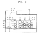
- FIG. 2 is a diagram illustrating the configuration of a wet-type electrophotographic image forming apparatus in accordance with an embodiment of the present invention.
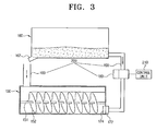
- FIG. 3 illustrates the main components of the wet-type electrophotographic image forming apparatus shown in FIG. 2 .
- the wet-type electrophotographic image forming apparatus includes a main body 110, a plurality of development units 160 for generating an image by supplying a developer to photosensitive medium 120, a plurality of developer cartridges 150 containing the developer, a plurality of developer collection units 200, and a control unit 210 ( FIG. 3 ).
- the main body 110 holds the development units 160, the developer cartridges 150, the developer collection units 200, and the control unit 210.
- the image forming apparatus also includes an intermediate transfer belt 175 and backup rollers 170 for transferring an image onto the intermediate transfer belt 175 from the photosensitive medium 120. Paper travels through the image forming apparatus along a printing paper transfer path P.
- the development unit 160 is placed above the developer cartridge 150 and generates an image by transferring developer to the photosensitive medium 120.
- the developer supplied to the development unit 160 from the developer cartridge 150 generates an image on the photosensitive medium 120, and residual developer is collected into the developer cartridge 150.
- At the bottom of the development unit 160 there is an outlet 162. Developer freely falls through the outlet 162 (by gravity) and is subsequently collected into the developer cartridges 150.
- the developer cartridge 150 is filled with developer.
- the developer cartridge 150 supplies developer to the development unit 160 and collects residual developer from the development unit 160.
- An agitator 152 rotating around a shaft 151 is installed inside the developer cartridge 150. The agitator 152 prevents the developer supplied to the development unit 160 from solidifying.
- the developer collection unit 200 is disposed between the development unit 160 and the developer cartridge 150, and collects residual developer in the development unit 160 into the developer cartridge 150.
- the developer collection unit 200 includes a drain 100, a pump 180 and a connection tube 190.
- the drain 100 is connected with the developer cartridge 150, and provides a natural collection passage where developer flowing out of the outlet 162 runs down to the drain 100 by free fall during the printing process.
- the connection tube 190 is connected with the development unit 160, the developer cartridge 150, and the pump 180.
- the connection tube 190 provides a passage for developer collected by the pump 180.
- a male fitting unit 172 and a female fitting unit 174 are disposed at the connection site between the connection tube 190 and the developer cartridge 150 to maintain a substantially fluid-tight seal.
- the pump 180 is connected with the connection tube 190 to cause developer to flow.
- the pump 180 can rotate in both forward and backward directions.
- the pump 180 supplies the developer from the developer cartridge 150 to the development unit 160 during the printing process.
- the pump 180 functions as a collection pump for collecting developer from the development unit 160 during the termination of a printing process. That is, the pump 180 rotates in a forward direction to supply developer to the development unit 160 from the developer cartridge 150 and, conversely, rotates in a backward direction to collect developer from the development unit 160 into the developer cartridge 150.
- An H-bridge circuit is preferably used to control the forward and backward rotations of the pump 180 with a single power source.
- the exemplary embodiment of the invention described herein uses a dual function pump (that is, the same pump is used to both supply and collect developer).
- Wet-type electrophotographic image forming apparatus are not limited to dual function pumps. It is possible to install separate supply and collection pumps, and use the control unit 210 to control the separate supply and collection pumps. With separate pumps, however, if the collection pump stops operating for any reason, such as by breaking, the supply pump continues to operate. Thus, the developer may overflow. Accordingly, it is preferable that one pump is used to both supply and collect developer.
- the control unit 210 controls the amount of developer to be collected into the developer cartridge 150 to prevent any overflow that may happen at the developer cartridge 150 during developer collection.
- the control unit 210 uses pulse width modulation (PWM) control to operate the pump.
- PWM pulse width modulation
- PWM is typically used to control motors and other power sources.
- PWM controls power by adjusting the duty cycle of a pulse signal and reduces unnecessary power consumption. For example, when a resistor is used to slow down the pumping speed of the pump 180, there is unnecessary power consumption.
- the use of a switching device for controlling the pumping speed through turning on and off the switching device controls the pumping speed without unnecessary power consumption.
- the ratio of 'ON' to 'OFF' is referred to as the duty cycle, and is commonly expressed as percentage (%).
- the pumping speed increases as the width of the 'ON' signal increases. Conversely, the pumping speed decreases as the width of 'ON' decreases.
- the control unit 210 limits the power supplied to the pump 180 and reduces unnecessary power consumption.
- the control unit 210 adjusts the duty cycle through PWM control, and, thus, adjusts the amount of the developer to be collected by the pump 180. As a result of this adjustment, the control unit 210 is capable of controlling the developer so that it does not overflow the drain 100 of the developer cartridge 150.
- FIG. 4 illustrates both the natural collection passage through which developer is naturally collected into the developer cartridge 150 and the forced collection passage through which developer is forcibly collected by the pump 180.
- Q1 is defined as the amount of developer that is naturally collected, that is, the amount of developer collected from the development unit 160 into the developer cartridge 150 through the outlet 162.
- Q1 is the amount of developer collected per unit time. Assuming that A is the cross-sectional area of the outlet 162 and v is the speed of the developer flowing out of the outlet 162, Q1 is determined by the following equation.
- Q ⁇ 1 v ⁇ A
- v ( 2 ⁇ gh ⁇ ) 1 / 2
- Equation 2 c ( 2 ⁇ gh ⁇ ) 1 / 2 ⁇ A
- Equation 4 ⁇ is a maximum capacity of the pump 180 per unit time, ⁇ is a control constant based on the driving force of the pump 180, and Pwm is a pumping speed factor.
- the control constant ⁇ is different depending on the pump type and specifications.
- Q3 has a predetermined constant value, which can be expressed by the following equation.
- Q ⁇ 3 ⁇
- Q3 should be greater than the added value of the Q1 and the Q2.
- This relationship can be defined according to Equations 3 to 5 and, expressed as follows. ⁇ > c ( 2 ⁇ gh ⁇ ) 1 / 2 ⁇ A + ⁇ ⁇ ⁇ ⁇ Pwm
- the pumping speed factor Pwm is determined as follows. Pwm ⁇ ⁇ - c ( 2 ⁇ gh ⁇ ) 1 / 2 ⁇ A / ⁇ ⁇ ⁇
- This Equation 7 represents the PWM determination equation.
- the duty cycle of the pump 180 for preventing overflow of developer at the drain 100 should be determined based on this PWM determination equation.
- the change in volume of developer due to temperature changes also need to be considered to accurately determine the PWM.
- the relationship between change in the volume of the fluid and change in temperature is proportional and can be expressed as ⁇ V ⁇ ⁇ T .
- the change in the volume of the fluid ⁇ V causes the height of the fluid to increase, and the height h measured from the top surface of the developer to the outlet 162 varies depending on the shape of a developing unit 160.
- the change in volume caused by temperature change gives rise to a change in height, that is, ⁇ h, between the top surface of the developer and the outlet.
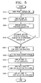
- the printing process starts when a user inputs a print instruction.
- the pump 180 is turned on, and developer starts to be supplied from the developer cartridge 150 to the development unit 160.
- the developer reaches a predetermined level of the development unit 160, natural developer collection is initiated at step S330. While the printing process continues, the developer supply executed by the pump 180 and the natural collection of developer through the outlet 162 occur simultaneously, so that the developer contained inside of the development unit 160 is maintained in an appropriate level.
- step S340 when the printing process is terminated or the printing process stops because of an error arising in the middle of the printing process, the pump 180 is turned off at step S350.
- the pump 180 is held in standby by being turned off for a predetermined time t at step S360. In this standby state, the natural collection of developer continues. Thus, the amount of developer contained inside the development unit 160 is reduced.
- the reason for placing the pump 180 in standby is to prevent an abrupt increase of developer flow into the developer cartridge 150 due to sudden collection of developer by the pump 180.
- the pump 180 rotates backward to proceed with forced collection of the developer into the developer cartridge 150 from the development unit 160 at step S370.
- the control unit 210 varies the duty cycle of the pump to allow developer remaining in the development unit 160 to be forcibly collected into the developer cartridge 150 without causing developer to overflow at the drain 100.
- the pump 180 is turned off at step S390, thus terminating developer collection.
- the amount of developer that is collected by the pump 180 is controlled to prevent a sudden collection of developer into the developer cartridge 150. As a result, it is possible to prevent overflow of developer caused by sudden collection of the developer. Accordingly, the disclosed wet-type electrophotographic image forming apparatus operates more stably.
Landscapes
- Physics & Mathematics (AREA)
- General Physics & Mathematics (AREA)
- Wet Developing In Electrophotography (AREA)
Description
- The present invention generally relates to a wet-type electrophotographic image forming apparatus that uses a liquid developer. More particularly, but not exclusively, the present invention relates to a wet-type electrophotographic image forming apparatus having a system for collecting residual developer from a development unit into a developer cartridge and a method for controlling the amount of collected developer.
- Generally, electrophotographic image forming apparatus can be classified as either dry-type image forming apparatus that use a dry powder developer or wet-type image forming apparatus that use a liquid developer. Dry-type and wet-type image forming apparatus each have distinctive characteristics. Generally, wet-type image forming apparatus have better print quality, with higher definition and resolution, than dry-type image forming apparatus. As digital cameras have become more popular, the demand for color image forming apparatus has greatly increased. They have especially increased demand for printers that produce high resolution, natural-color, prints.
- To produce a desired level of print quality with a wet-type image forming apparatus, it is necessary to provide a developing unit with a larger amount of developer than the amount actually required for printing. For this reason, excess, unused developer is collected and returned to a developer cartridge.
FIG. 1 schematically illustrates a conventional wet-type electrophotographic image forming apparatus that provides and collects developer. - In the apparatus shown in
FIG. 1 , when a user enters a printing instruction, a supply pump (not illustrated) starts to supply developer to adevelopment unit 16 from adeveloper cartridge 15. When thedevelopment unit 16 is filled with developer to a certain level, the developer starts to collect naturally. That is, any excess developer returns to thedeveloper cartridge 15 by exiting adeveloper outlet 17, entering into adrain 18, and flowing into thedeveloper cartridge 15, due to gravity. While printing continues, the supply of developer by the supply pump and the natural collection of the developer occur concurrently. As a result, thedevelopment unit 16 maintains an adequate level of developer. - When printing is terminated, or, when printing stops due to an error in the middle of the printing process, a
collection pump 12 is activated to collect the developer and return the developer throughconnection tube 13. Since the natural collection of the developer continues to take place, the developer collects into thedeveloper cartridge 15 more rapidly. After the collection of the residual developer is completed, thecollection pump 12 is stopped and, thus, the developer collection is terminated. - However, when the
collection pump 12 operates, developer is returned to the developer cartridge through bothdrain 18 andconnection tube 13. This simultaneous bi-directional inflow of the developer causes the level of developer contained within thedeveloper cartridge 15 to increase. This increased level of developer causes air within thedeveloper cartridge 15 to compress. The compressed air leaks out of thedrain 18, creating anairflow 20 in the opposite direction of developer flow. This causes the developer to overflow and contaminate various interior parts of the electrophotographic image forming apparatus. In addition to the contamination, the overflowing developer causes malfunctions. Furthermore, the overflowing developer may leak out of the apparatus, causing severe contamination outside of the apparatus. - United States patent application publication number
US 2004/0086291 A1 discloses a developing device for developing a latent image formed on an image carrier with a developing liquid and includes a liquid storing section for storing the liquid consisting of a developing substance and a carrier liquid. A developer carrier deposits the liquid feed from the liquid storing section thereon. A float type liquid level sensor senses a liquid level in the liquid storing section. The liquid level sensor includes a magnetic force generating member for generating a magnetic force, a magnetic force sensing device for sensing the magnetic force and floats moveable up and down in accordance with the liquid level in the liquid storing section a distance between the magnetic force generating member and the magnetic force sensing device varies in accordance with the movement of the floats, allowing the liquid level to be determined on the basis of the output of the magnetic force sensing device. An image forming apparatus including the developing device is also disclosed. -
US 6,120,977 B1 discloses a developing device wherein liquid developer is recovered into a developer reservoir via a drain connected to said reservoir. - Accordingly, there is a need for an improved apparatus for returning excess developer in a wet-type electrophotographic image forming apparatus, and a wet-type electrophotographic image forming apparatus employing the same.
- An aim of embodiments of the present invention is to address at least the above problems and/or disadvantages and to provide at least the advantages described below. Embodiments of the present invention advantageously provide a wet-type electrophotographic image forming apparatus that is capable of adjusting the collection amount of developer that flows into a developer cartridge in the course of collecting the developer, and a method for controlling the collection amount of the developer.
- In accordance with one aspect of the present invention, there is provided a wet-type electrophotographic image forming apparatus according to claim 1 and a method for collecting liquid developer according to claim 4.
- In accordance with another aspect of the present invention, there is provided a method for collecting a developer remaining in a development unit into a developer cartridge in a wet-type electrophotographic image forming apparatus, including the steps of turning on a pump to supply developer to the development unit, collecting developer remaining in the development unit in a natural manner, collecting developer in a compulsory manner, and controlling the amount of the compulsorily collected developer when a printing operation is terminated or an error occurs during the printing operation.
- Preferably, the step of collecting the developer in a compulsory manner includes the steps of turning off a pump to stop developer supply to the development unit, and collecting the developer by rotating the pump in a backward direction.
- The step of collecting the developer remaining in the development unit in a compulsory manner preferably further includes the step of collecting the developer by adjusting the duty cycle of the pump. It is also preferable that the step of collecting the remaining developer further includes the step of stopping the pump from operating for a predetermined period after the developer supply is stopped.
- In accordance with another aspect of the present invention, there is provided a wet-type electrophotographic image forming apparatus, comprising: a development unit for developing an image on a photosensitive medium; a developer cartridge for supplying developer to the development unit; a drain providing a developer flow passage for allowing developer remaining in the development unit to be collected into the developer cartridge in a natural manner; a pump for collecting developer in the development unit into the developer cartridge in a forced manner; and a control unit for controlling the pump to prevent developer from overflowing during developer collection.
- For a better understanding of the invention, and to show how embodiments of the same may be carried into effect, reference will now be made, by way of example, to the accompanying diagrammatic drawings in which:
-
FIG. 1 is a schematic view of a conventional wet-type electrophotographic image forming apparatus; -
FIG. 2 is a schematic view of a wet-type electrophotographic image forming apparatus in accordance with an embodiment of the present invention; -
FIGS. 3 and4 are schematic views of the main parts of the wet-type electrophotographic image forming apparatus as shown inFIG. 2 ; and -
FIG. 5 is a flowchart of the method of controlling the collection of developer in accordance with the embodiment of the present invention. - Throughout the drawings, the same drawing reference numerals will be understood to refer to the same elements, features, and structures.
- The matters defined in the description such as a detailed construction and elements are provided to assist in a comprehensive understanding of the embodiments of the invention.
- Accordingly, those of ordinary skill in the art will recognize that various changes and modifications of the embodiments described herein can be made without departing from the scope of the invention as defined by the claims. Also, descriptions of well-known functions and constructions are omitted for clarity and conciseness.
-
FIG. 2 is a diagram illustrating the configuration of a wet-type electrophotographic image forming apparatus in accordance with an embodiment of the present invention.FIG. 3 illustrates the main components of the wet-type electrophotographic image forming apparatus shown inFIG. 2 . - Referring to
FIG. 2 , the wet-type electrophotographic image forming apparatus includes amain body 110, a plurality ofdevelopment units 160 for generating an image by supplying a developer tophotosensitive medium 120, a plurality ofdeveloper cartridges 150 containing the developer, a plurality ofdeveloper collection units 200, and a control unit 210 (FIG. 3 ). Themain body 110 holds thedevelopment units 160, thedeveloper cartridges 150, thedeveloper collection units 200, and thecontrol unit 210. The image forming apparatus also includes anintermediate transfer belt 175 andbackup rollers 170 for transferring an image onto theintermediate transfer belt 175 from thephotosensitive medium 120. Paper travels through the image forming apparatus along a printing paper transfer path P. - Referring to
FIGS. 2 and3 , thedevelopment unit 160 is placed above thedeveloper cartridge 150 and generates an image by transferring developer to thephotosensitive medium 120. The developer supplied to thedevelopment unit 160 from thedeveloper cartridge 150 generates an image on thephotosensitive medium 120, and residual developer is collected into thedeveloper cartridge 150. At the bottom of thedevelopment unit 160, there is anoutlet 162. Developer freely falls through the outlet 162 (by gravity) and is subsequently collected into thedeveloper cartridges 150. - The
developer cartridge 150 is filled with developer. Thedeveloper cartridge 150 supplies developer to thedevelopment unit 160 and collects residual developer from thedevelopment unit 160. Anagitator 152 rotating around ashaft 151 is installed inside thedeveloper cartridge 150. Theagitator 152 prevents the developer supplied to thedevelopment unit 160 from solidifying. - The
developer collection unit 200 is disposed between thedevelopment unit 160 and thedeveloper cartridge 150, and collects residual developer in thedevelopment unit 160 into thedeveloper cartridge 150. Thedeveloper collection unit 200 includes adrain 100, apump 180 and aconnection tube 190. - The
drain 100 is connected with thedeveloper cartridge 150, and provides a natural collection passage where developer flowing out of theoutlet 162 runs down to thedrain 100 by free fall during the printing process. Theconnection tube 190 is connected with thedevelopment unit 160, thedeveloper cartridge 150, and thepump 180. Theconnection tube 190 provides a passage for developer collected by thepump 180. A malefitting unit 172 and a femalefitting unit 174 are disposed at the connection site between theconnection tube 190 and thedeveloper cartridge 150 to maintain a substantially fluid-tight seal. - The
pump 180 is connected with theconnection tube 190 to cause developer to flow. Preferably, thepump 180 can rotate in both forward and backward directions. As mentioned above, thepump 180 supplies the developer from thedeveloper cartridge 150 to thedevelopment unit 160 during the printing process. In addition, thepump 180 functions as a collection pump for collecting developer from thedevelopment unit 160 during the termination of a printing process. That is, thepump 180 rotates in a forward direction to supply developer to thedevelopment unit 160 from thedeveloper cartridge 150 and, conversely, rotates in a backward direction to collect developer from thedevelopment unit 160 into thedeveloper cartridge 150. An H-bridge circuit is preferably used to control the forward and backward rotations of thepump 180 with a single power source. - The exemplary embodiment of the invention described herein uses a dual function pump (that is, the same pump is used to both supply and collect developer). Wet-type electrophotographic image forming apparatus, however, are not limited to dual function pumps. It is possible to install separate supply and collection pumps, and use the
control unit 210 to control the separate supply and collection pumps. With separate pumps, however, if the collection pump stops operating for any reason, such as by breaking, the supply pump continues to operate. Thus, the developer may overflow. Accordingly, it is preferable that one pump is used to both supply and collect developer. - The
control unit 210 controls the amount of developer to be collected into thedeveloper cartridge 150 to prevent any overflow that may happen at thedeveloper cartridge 150 during developer collection. In particular, thecontrol unit 210 uses pulse width modulation (PWM) control to operate the pump. - PWM is typically used to control motors and other power sources. PWM controls power by adjusting the duty cycle of a pulse signal and reduces unnecessary power consumption. For example, when a resistor is used to slow down the pumping speed of the
pump 180, there is unnecessary power consumption. In contrast, the use of a switching device for controlling the pumping speed through turning on and off the switching device controls the pumping speed without unnecessary power consumption. The ratio of 'ON' to 'OFF' is referred to as the duty cycle, and is commonly expressed as percentage (%). The pumping speed increases as the width of the 'ON' signal increases. Conversely, the pumping speed decreases as the width of 'ON' decreases. Thus, by controlling the pulse width to control thepump 180, thecontrol unit 210 limits the power supplied to thepump 180 and reduces unnecessary power consumption. - In other words, PWM controls the pumping speed by controlling the duty cycle. Therefore, the
control unit 210 adjusts the duty cycle through PWM control, and, thus, adjusts the amount of the developer to be collected by thepump 180. As a result of this adjustment, thecontrol unit 210 is capable of controlling the developer so that it does not overflow thedrain 100 of thedeveloper cartridge 150. - With reference to
FIG. 4 , a method for setting the duty cycle for controlling the collection amount of the developer to prevent overflow of the developer at thedrain 100 will be described in detail.FIG. 4 illustrates both the natural collection passage through which developer is naturally collected into thedeveloper cartridge 150 and the forced collection passage through which developer is forcibly collected by thepump 180. - First, Q1 is defined as the amount of developer that is naturally collected, that is, the amount of developer collected from the
development unit 160 into thedeveloper cartridge 150 through theoutlet 162. In short, Q1 is the amount of developer collected per unit time. Assuming that A is the cross-sectional area of theoutlet 162 and v is the speed of the developer flowing out of theoutlet 162, Q1 is determined by the following equation.
- Assuming that h is the average height from the
outlet 162 to the top surface of the developer contained in thedevelopment unit 160, v can be obtained in accordance with Torricelli's theorem, which is defined as:
- This equation is theoretical. In reality, however, the outlet orifice has a certain friction. Hence, assuming that the efflux coefficient is c,

- The efflux coefficient is variable depending on the shape of an outlet. When the outlet has a circular shape, the efflux coefficient ranges from approximately 0.93 to approximately 0.98. Substituting Equation 2' into Equation 1, the following relationship is established as:

- Meanwhile, when it is assumed that the amount of developer collected into the
developer cartridge 150 per unit time by thepump 180 is expressed as Q2, the following equation is produced:
- In Equation 4, β is a maximum capacity of the
pump 180 per unit time, γ is a control constant based on the driving force of thepump 180, and Pwm is a pumping speed factor. The control constant γ is different depending on the pump type and specifications. - When the maximum amount of the developer that can flow into or flow out of the
developer cartridge 150 through thedrain 100 per unit time is assumed to be Q3, Q3 has a predetermined constant value, which can be expressed by the following equation.
- To prevent overflow of developer at the
drain 100, Q3 should be greater than the added value of the Q1 and the Q2. This relationship can be defined according to Equations 3 to 5 and, expressed as follows.
- As a result, the pumping speed factor Pwm is determined as follows.

- This Equation 7 represents the PWM determination equation. The duty cycle of the
pump 180 for preventing overflow of developer at thedrain 100 should be determined based on this PWM determination equation. - The change in volume of developer due to temperature changes also need to be considered to accurately determine the PWM. The relationship between change in the volume of the fluid and change in temperature is proportional and can be expressed as ΔV ∝ ΔT. The change in the volume of the fluid ΔV causes the height of the fluid to increase, and the height h measured from the top surface of the developer to the
outlet 162 varies depending on the shape of a developingunit 160. Hence, the change in volume caused by temperature change gives rise to a change in height, that is, Δh, between the top surface of the developer and the outlet. As a result, it is necessary to consider the shape of the development apparatus. - With reference to
FIGS. 3 to 5 , the operation of the disclosed exemplary embodiment wet-type electrophotographic image forming apparatus with the above-described configuration will be explained in detail. - At step S310, the printing process starts when a user inputs a print instruction. At step S320, the
pump 180 is turned on, and developer starts to be supplied from thedeveloper cartridge 150 to thedevelopment unit 160. At this time, when the developer reaches a predetermined level of thedevelopment unit 160, natural developer collection is initiated at step S330. While the printing process continues, the developer supply executed by thepump 180 and the natural collection of developer through theoutlet 162 occur simultaneously, so that the developer contained inside of thedevelopment unit 160 is maintained in an appropriate level. - As step S340, when the printing process is terminated or the printing process stops because of an error arising in the middle of the printing process, the
pump 180 is turned off at step S350. Thepump 180 is held in standby by being turned off for a predetermined time t at step S360. In this standby state, the natural collection of developer continues. Thus, the amount of developer contained inside thedevelopment unit 160 is reduced. The reason for placing thepump 180 in standby is to prevent an abrupt increase of developer flow into thedeveloper cartridge 150 due to sudden collection of developer by thepump 180. - When some amount of developer contained inside the
development unit 160 is collected through natural collection, thepump 180 rotates backward to proceed with forced collection of the developer into thedeveloper cartridge 150 from thedevelopment unit 160 at step S370. At step S380, thecontrol unit 210 varies the duty cycle of the pump to allow developer remaining in thedevelopment unit 160 to be forcibly collected into thedeveloper cartridge 150 without causing developer to overflow at thedrain 100. When all the developer is collected, thepump 180 is turned off at step S390, thus terminating developer collection. - As explained above, the amount of developer that is collected by the
pump 180 is controlled to prevent a sudden collection of developer into thedeveloper cartridge 150. As a result, it is possible to prevent overflow of developer caused by sudden collection of the developer. Accordingly, the disclosed wet-type electrophotographic image forming apparatus operates more stably.
Claims (8)
- A wet-type electrophotographic image forming apparatus, comprising:a development unit (160) for developing an image on a photosensitive medium (120);a developer cartridge (150) for supplying developer to the development unit (160) ;a developer collection unit (200) disposed between the development unit (160) and the developer cartridge (150) for collecting developer remaining within the development unit (160) into the developer cartridge (150); anda control unit (210) for controlling the amount of developer to be collected through the developer collection unit (200) to prevent an overflow of developer at the developer cartridge (150) while the developer is collected, the control unit (210) being operable to control the pump (180) by comparing the amount of forcibly collected developer with the amount of naturally collected developer; the developer collection unit (200) further comprisinga drain (100) connected with the developer cartridge 150 for providing a developer flow passage for allowing developer remaining in the development unit (160) to be collected into the developer cartridge (150) in a natural manner; anda pump (180) for collecting developer in the development unit (160) into the developer cartridge (150) in a forced manner, the development unit (160), the developer cartridge (150), and the pump (180) being connected by a connection tube (190).
- The wet-type electrophotographic image forming apparatus of claim 1,
wherein the pump (180) is operable to supply and collect the developer by a forward rotation and a backward rotation. - The wet-type electrophotographic image forming apparatus of claim 1 or 2,
wherein the control unit (210) is operable to control the pump using pulse width modulation (PWM). - A method for collecting developer remaining in a development unit (160) into a developer cartridge (150) in a wet-type electrophotographic image forming apparatus, the method comprising the steps of:turning on a pump (180) to supply developer to the development unit (160), the development unit (160), the developer cartridge (150), and the pump (180) being connected by tube (190);collecting developer remaining in the development unit (160) in a natural manner by allowing developer to flow out of the development unit (160) through an outlet (162), and collecting the developer into the developer cartridge (150) through a drain (100) connected with the developer cartridge (150),turning an said pump (180) to collect developer from development unit (160) into said developer cartridge (150) in a forced manner, and controlling the forced collection when a printing operation is terminated or an error occurs during the printing operation,wherein the step of controlling the forced collection to prevent developer from overflowing comprises comparing the amount of forcibly collected developer with the amount of naturally collected developer and controlling the pump accordingly.
- The method of claim 4, wherein the step of collecting the developer remaining in the development unit (160) in the forced manner comprises the sub-steps of:turning off a pump (180) to stop a developer supply to the development unit (160); andcollecting the developer by rotating the pump (180) in a backward direction.
- The method of claim 5, further comprising the sub-step of stopping the pump (180) from operating for a predetermined period after the developer supply is stopped.
- The method of claim 5 or 6, further comprising the sub-step of collecting the developer by adjusting a duty cycle of the pump (180).
- The method of claim 7, wherein the duty cycle of the pump (180) is adjusted based on the equation:

where η is the maximum amount of developer that can flow into or flow out of the developer cartridge (150) through the drain (100), c is the efflux coefficient for the drain, g is gravity, h is the height of developer in the development unit (160), A is the cross-sectional area of the outlet (162), β is a maximum capacity of the pump per unit time, γ is a control constant based on the driving force of the pump, and Pwm is a pumping speed factor.
Applications Claiming Priority (1)
| Application Number | Priority Date | Filing Date | Title |
|---|---|---|---|
| KR1020040067986A KR100555641B1 (en) | 2004-08-27 | 2004-08-27 | Wet electrophotographic image forming apparatus and developer collection control method |
Publications (2)
| Publication Number | Publication Date |
|---|---|
| EP1630623A1 EP1630623A1 (en) | 2006-03-01 |
| EP1630623B1 true EP1630623B1 (en) | 2008-05-14 |
Family
ID=36093340
Family Applications (1)
| Application Number | Title | Priority Date | Filing Date |
|---|---|---|---|
| EP05255114A Expired - Lifetime EP1630623B1 (en) | 2004-08-27 | 2005-08-18 | Wet-type electrophotographic image forming apparatus and method for controlling collection of developer |
Country Status (5)
| Country | Link |
|---|---|
| US (1) | US7412179B2 (en) |
| EP (1) | EP1630623B1 (en) |
| KR (1) | KR100555641B1 (en) |
| CN (1) | CN100422873C (en) |
| DE (1) | DE602005006681D1 (en) |
Families Citing this family (1)
| Publication number | Priority date | Publication date | Assignee | Title |
|---|---|---|---|---|
| US10216120B2 (en) * | 2015-10-29 | 2019-02-26 | Hp Indigo B.V. | Liquid electrophotographic printers |
Family Cites Families (11)
| Publication number | Priority date | Publication date | Assignee | Title |
|---|---|---|---|---|
| JP2804818B2 (en) | 1989-06-21 | 1998-09-30 | オリンパス光学工業株式会社 | Liquid developing device |
| JP2804788B2 (en) | 1989-06-29 | 1998-09-30 | オリンパス光学工業株式会社 | Liquid developing device |
| JPH0980909A (en) | 1995-09-12 | 1997-03-28 | Fujitsu Ltd | Developer discharge device of developing unit |
| JP3214404B2 (en) * | 1997-07-04 | 2001-10-02 | 岩崎通信機株式会社 | Wet plate making machine |
| KR100331311B1 (en) * | 1998-05-13 | 2002-05-09 | 윤종용 | Apparatus for cleaning carrier for liquid printer |
| JP2000010411A (en) * | 1998-06-19 | 2000-01-14 | Nec Niigata Ltd | Mechanism and method for stirring developer |
| KR100311024B1 (en) * | 1998-09-19 | 2002-08-27 | 삼성전자 주식회사 | Developer supply system of reversible pump and wet developing machine using the same |
| JP4038312B2 (en) * | 1999-10-26 | 2008-01-23 | 株式会社リコー | Wet image forming device |
| US6694112B2 (en) * | 2000-06-28 | 2004-02-17 | Ricoh Company, Ltd. | Developing device using a developing liquid including a rotatable agitator in a developing liquid reservoir and image forming apparatus including the same |
| JP2002023505A (en) * | 2000-07-06 | 2002-01-23 | Ricoh Co Ltd | Image forming device |
| KR100503808B1 (en) * | 2003-09-05 | 2005-07-26 | 삼성전자주식회사 | Developing apparatus for liquid type eletrophotographic image forming device |
-
2004
- 2004-08-27 KR KR1020040067986A patent/KR100555641B1/en not_active Expired - Fee Related
-
2005
- 2005-06-20 US US11/155,626 patent/US7412179B2/en not_active Expired - Fee Related
- 2005-08-18 EP EP05255114A patent/EP1630623B1/en not_active Expired - Lifetime
- 2005-08-18 DE DE602005006681T patent/DE602005006681D1/en not_active Expired - Fee Related
- 2005-08-18 CN CNB2005100924161A patent/CN100422873C/en not_active Expired - Fee Related
Also Published As
| Publication number | Publication date |
|---|---|
| EP1630623A1 (en) | 2006-03-01 |
| CN1740921A (en) | 2006-03-01 |
| CN100422873C (en) | 2008-10-01 |
| US7412179B2 (en) | 2008-08-12 |
| KR100555641B1 (en) | 2006-03-03 |
| DE602005006681D1 (en) | 2008-06-26 |
| US20060045553A1 (en) | 2006-03-02 |
Similar Documents
| Publication | Publication Date | Title |
|---|---|---|
| US8152293B2 (en) | Oil reservoir with float level sensor | |
| US7885565B2 (en) | Development device, image forming apparatus and image forming method | |
| US6625404B2 (en) | Apparatus for controlling the amount of developer material and toner concentration | |
| US8688012B2 (en) | Developing device and image forming apparatus | |
| US5353102A (en) | Two component developing apparatus in a printer | |
| JP2003167442A (en) | A toner recycling control method for electrophotographic equipment using a highly viscous liquid developer | |
| US7412179B2 (en) | Wet-type electrophotographic image forming apparatus and method for controlling collection of developer | |
| CN101373359A (en) | Developing device, developing method, and image forming device | |
| KR100461301B1 (en) | Wet electrophotographic image forming machine and method for recognizing life of a development cartrage thereof | |
| JP2000172076A (en) | Image forming device | |
| JP3971000B2 (en) | Developing device, developing method, and image forming apparatus | |
| JP2008033171A (en) | Toner storage container, developing device and image forming apparatus having them | |
| US7010251B2 (en) | Toner conveyance device and image forming apparatus equipped therewith | |
| KR100333817B1 (en) | Apparstus for delivering developer of a liquid electrophotographic color printer | |
| US7257354B2 (en) | Device and method for the replacement of out-of-date developer | |
| US20070253744A1 (en) | Device and method for the replacement of expired developer | |
| JP2009098294A (en) | Developing device, toner replenishing method thereof, and image forming apparatus including the same | |
| US6987935B2 (en) | Developer supply and recovery system used with wet electro-photographic image forming apparatus, and method thereof | |
| JP4040317B2 (en) | Developing device and image forming apparatus having the same | |
| JP5691277B2 (en) | Developing device and image forming apparatus | |
| JP5733613B2 (en) | Developing device and image forming apparatus | |
| JP2006208564A (en) | Developing device and image forming apparatus | |
| JP3872937B2 (en) | Developing device and image forming apparatus | |
| JP2007163546A (en) | Toner supply device and image forming apparatus | |
| WO1992003765A1 (en) | Liquid toner replenishment system |
Legal Events
| Date | Code | Title | Description |
|---|---|---|---|
| PUAI | Public reference made under article 153(3) epc to a published international application that has entered the european phase |
Free format text: ORIGINAL CODE: 0009012 |
|
| AK | Designated contracting states |
Kind code of ref document: A1 Designated state(s): AT BE BG CH CY CZ DE DK EE ES FI FR GB GR HU IE IS IT LI LT LU LV MC NL PL PT RO SE SI SK TR |
|
| AX | Request for extension of the european patent |
Extension state: AL BA HR MK YU |
|
| 17P | Request for examination filed |
Effective date: 20060203 |
|
| AKX | Designation fees paid |
Designated state(s): DE GB NL |
|
| 17Q | First examination report despatched |
Effective date: 20060410 |
|
| GRAP | Despatch of communication of intention to grant a patent |
Free format text: ORIGINAL CODE: EPIDOSNIGR1 |
|
| GRAS | Grant fee paid |
Free format text: ORIGINAL CODE: EPIDOSNIGR3 |
|
| GRAA | (expected) grant |
Free format text: ORIGINAL CODE: 0009210 |
|
| RAP1 | Party data changed (applicant data changed or rights of an application transferred) |
Owner name: SAMSUNG ELECTRONICS CO., LTD. |
|
| AK | Designated contracting states |
Kind code of ref document: B1 Designated state(s): DE GB NL |
|
| REG | Reference to a national code |
Ref country code: GB Ref legal event code: FG4D |
|
| REF | Corresponds to: |
Ref document number: 602005006681 Country of ref document: DE Date of ref document: 20080626 Kind code of ref document: P |
|
| PGFP | Annual fee paid to national office [announced via postgrant information from national office to epo] |
Ref country code: DE Payment date: 20080826 Year of fee payment: 4 |
|
| PGFP | Annual fee paid to national office [announced via postgrant information from national office to epo] |
Ref country code: NL Payment date: 20080831 Year of fee payment: 4 |
|
| PLBE | No opposition filed within time limit |
Free format text: ORIGINAL CODE: 0009261 |
|
| STAA | Information on the status of an ep patent application or granted ep patent |
Free format text: STATUS: NO OPPOSITION FILED WITHIN TIME LIMIT |
|
| 26N | No opposition filed |
Effective date: 20090217 |
|
| REG | Reference to a national code |
Ref country code: NL Ref legal event code: V1 Effective date: 20100301 |
|
| GBPC | Gb: european patent ceased through non-payment of renewal fee |
Effective date: 20090818 |
|
| PG25 | Lapsed in a contracting state [announced via postgrant information from national office to epo] |
Ref country code: NL Free format text: LAPSE BECAUSE OF NON-PAYMENT OF DUE FEES Effective date: 20100301 Ref country code: DE Free format text: LAPSE BECAUSE OF NON-PAYMENT OF DUE FEES Effective date: 20100302 |
|
| PG25 | Lapsed in a contracting state [announced via postgrant information from national office to epo] |
Ref country code: GB Free format text: LAPSE BECAUSE OF NON-PAYMENT OF DUE FEES Effective date: 20090818 |
|
| REG | Reference to a national code |
Ref country code: GB Ref legal event code: 732E Free format text: REGISTERED BETWEEN 20170406 AND 20170412 |