EP1630366A1 - Two-step roller cam follower having angled lock pin - Google Patents
Two-step roller cam follower having angled lock pin Download PDFInfo
- Publication number
- EP1630366A1 EP1630366A1 EP05076819A EP05076819A EP1630366A1 EP 1630366 A1 EP1630366 A1 EP 1630366A1 EP 05076819 A EP05076819 A EP 05076819A EP 05076819 A EP05076819 A EP 05076819A EP 1630366 A1 EP1630366 A1 EP 1630366A1
- Authority
- EP
- European Patent Office
- Prior art keywords
- latch pin
- slider
- roller
- shaft
- lift
- Prior art date
- Legal status (The legal status is an assumption and is not a legal conclusion. Google has not performed a legal analysis and makes no representation as to the accuracy of the status listed.)
- Withdrawn
Links
- 238000002485 combustion reaction Methods 0.000 claims description 6
- 238000005452 bending Methods 0.000 description 8
- 230000008901 benefit Effects 0.000 description 3
- 230000009849 deactivation Effects 0.000 description 3
- 239000000446 fuel Substances 0.000 description 3
- 239000003921 oil Substances 0.000 description 3
- 230000004913 activation Effects 0.000 description 2
- 230000000994 depressogenic effect Effects 0.000 description 2
- 238000010304 firing Methods 0.000 description 2
- 230000000712 assembly Effects 0.000 description 1
- 238000000429 assembly Methods 0.000 description 1
- 230000006835 compression Effects 0.000 description 1
- 238000007906 compression Methods 0.000 description 1
- 238000010276 construction Methods 0.000 description 1
- 230000006872 improvement Effects 0.000 description 1
- 230000002452 interceptive effect Effects 0.000 description 1
- 239000010687 lubricating oil Substances 0.000 description 1
- 230000009467 reduction Effects 0.000 description 1
- 230000003319 supportive effect Effects 0.000 description 1
Images

Classifications
-
- F—MECHANICAL ENGINEERING; LIGHTING; HEATING; WEAPONS; BLASTING
- F01—MACHINES OR ENGINES IN GENERAL; ENGINE PLANTS IN GENERAL; STEAM ENGINES
- F01L—CYCLICALLY OPERATING VALVES FOR MACHINES OR ENGINES
- F01L1/00—Valve-gear or valve arrangements, e.g. lift-valve gear
- F01L1/12—Transmitting gear between valve drive and valve
- F01L1/18—Rocking arms or levers
- F01L1/181—Centre pivot rocking arms
- F01L1/182—Centre pivot rocking arms the rocking arm being pivoted about an individual fulcrum, i.e. not about a common shaft
-
- F—MECHANICAL ENGINEERING; LIGHTING; HEATING; WEAPONS; BLASTING
- F01—MACHINES OR ENGINES IN GENERAL; ENGINE PLANTS IN GENERAL; STEAM ENGINES
- F01L—CYCLICALLY OPERATING VALVES FOR MACHINES OR ENGINES
- F01L1/00—Valve-gear or valve arrangements, e.g. lift-valve gear
- F01L1/12—Transmitting gear between valve drive and valve
- F01L1/18—Rocking arms or levers
-
- F—MECHANICAL ENGINEERING; LIGHTING; HEATING; WEAPONS; BLASTING
- F01—MACHINES OR ENGINES IN GENERAL; ENGINE PLANTS IN GENERAL; STEAM ENGINES
- F01L—CYCLICALLY OPERATING VALVES FOR MACHINES OR ENGINES
- F01L1/00—Valve-gear or valve arrangements, e.g. lift-valve gear
- F01L1/12—Transmitting gear between valve drive and valve
- F01L1/18—Rocking arms or levers
- F01L1/185—Overhead end-pivot rocking arms
-
- F—MECHANICAL ENGINEERING; LIGHTING; HEATING; WEAPONS; BLASTING
- F01—MACHINES OR ENGINES IN GENERAL; ENGINE PLANTS IN GENERAL; STEAM ENGINES
- F01L—CYCLICALLY OPERATING VALVES FOR MACHINES OR ENGINES
- F01L13/00—Modifications of valve-gear to facilitate reversing, braking, starting, changing compression ratio, or other specific operations
- F01L13/0015—Modifications of valve-gear to facilitate reversing, braking, starting, changing compression ratio, or other specific operations for optimising engine performances by modifying valve lift according to various working parameters, e.g. rotational speed, load, torque
- F01L13/0036—Modifications of valve-gear to facilitate reversing, braking, starting, changing compression ratio, or other specific operations for optimising engine performances by modifying valve lift according to various working parameters, e.g. rotational speed, load, torque the valves being driven by two or more cams with different shape, size or timing or a single cam profiled in axial and radial direction
-
- F—MECHANICAL ENGINEERING; LIGHTING; HEATING; WEAPONS; BLASTING
- F01—MACHINES OR ENGINES IN GENERAL; ENGINE PLANTS IN GENERAL; STEAM ENGINES
- F01L—CYCLICALLY OPERATING VALVES FOR MACHINES OR ENGINES
- F01L1/00—Valve-gear or valve arrangements, e.g. lift-valve gear
- F01L1/12—Transmitting gear between valve drive and valve
- F01L1/18—Rocking arms or levers
- F01L2001/186—Split rocking arms, e.g. rocker arms having two articulated parts and means for varying the relative position of these parts or for selectively connecting the parts to move in unison
-
- F—MECHANICAL ENGINEERING; LIGHTING; HEATING; WEAPONS; BLASTING
- F01—MACHINES OR ENGINES IN GENERAL; ENGINE PLANTS IN GENERAL; STEAM ENGINES
- F01L—CYCLICALLY OPERATING VALVES FOR MACHINES OR ENGINES
- F01L2305/00—Valve arrangements comprising rollers
- F01L2305/02—Mounting of rollers
Definitions
- the present invention relates to roller finger followers used for variable valve actuation in overhead cam type internal combustion engines, and more particularly to a roller finger follower wherein a locking pin is disposed at an angle to a radius of rotation of a slider arm pivotably mounted in a follower body.
- Roller Finger Followers are widely used in overhead cam internal combustion engines to sequentially open and close the cylinder intake and exhaust valves.
- the RFF serves to transfer and translate rotary motion of a cam shaft lobe into a pivotal motion of the RFF to thereby open and close an associated valve.
- valves may be opened to only a low lift position to conserve fuel, and that at times of high torque demand, the valves may be opened wider to a high lift position to admit more fuel. It is known in the art to accomplish this by de-activating a portion of the valve train or limiting the opening of one or more valves associated with pro-selected cylinders in any of various ways.
- One way is by providing a special two-step RFF having a variably latchable and de-latchable central slider arm which may be positioned for contact with a high lift lobe of the cam shaft.
- Such a two-step RFF typically is also configured with rollers disposed at each side of the slider arm for contact with low lift lobes of the cam shaft on either side of the high-lift lobe.
- the two-step RFF causes low lift of the associated valve when the slider arm of the RFF is in a de-latched or deactivated position, and high lift of the associated valve when the slider arm of the RFF is latched in an activated position to engage the high lift lobe of the cam shaft.
- One such two-step RFF known in the art comprises a generally elongate body having a pallet end in contact with an axially movable valve stem and an opposing socket end in contact with a stationary pivot such as, for example, a hydraulic lash adjuster (HLA).
- a moveable and therefore deactivatable high lift slider is positioned central to the RFF body. Rollers are rotatably mounted on each side of the slider on a non-rotatable shaft fixed to the body. The rollers ride on narrow bearings, as for example needle bearings. End washers are used to rotatably fix the rollers and bearings to the shaft and to restrain the rollers and bearings from moving laterally on the shaft.
- the width of the bearings in this prior art follower is limited to the width of the rollers themselves. Further, because the bearings are disposed outside the body side walls, the bearings are substantially shielded from flow of lubricating oil within the RFF body.
- roller finger follower Another prior art two-step roller finger follower is disclosed in US Patent No. 6,755,167 B2, issued June 29, 2004, the relevant disclosure of which is incorporated herein by reference.
- an elongate body having first and second side members defines coaxially disposed shaft orifices.
- a pallet end and a socket end interconnect with the first and second side members to define a central slider arm aperture and a latch pin channel.
- the socket end is adapted to mate with a mounting element such as an hydraulic lash adjuster, and the pallet end is adapted to mate with a valve stem, pintle, lifter, or the like.
- a slider arm for engaging a high-lift cam lobe is disposed in the slider arm aperture and has first and second ends, the first end of the slider arm being pivotally mounted to one end of the body and the second end defining a slider tip for engaging an activation/deactivation latch.
- the latch pin is slidably disposed in the latch pin channel, the latch pin having a nose section for selectively engaging the slider tip.
- a spool-shaped roller comprising a shaft and opposed roller elements fixedly attached to ends of the shaft is rotatably disposed in the shaft orifices, the roller being adapted to follow the surface motion of a low-lift cam lobes.
- the shaft is journalled in roller or needle bearings which extend between and through both the first and second shaft orifices, being thus exposed to normal copious oil flow through central regions of the RFF.
- a drawback of this prior art roller finger follower is that the axis of the locking pin intersects the axis of the pivot pin for the slider; i.e., the motion of the locking pin is along an extension of a pivot pin and slider tip radius.
- the motion of the slider tip is substantially orthogonal to the path of the locking pin.
- This relationship necessitates that the locking pin extend from its supporting bore in order to engage the slider tip, thereby engendering a bending moment on the locking pin.
- Providing acceptable support for such bending moment requires that the locking pin have a relatively long bore and large diameter, thus increasing undesirably the size of the follower body and hence the overall follower assembly.
- a further drawback of such a roller finger follower is that the locking pin can inadvertently engage the wrong side of the slider tip if the locking pin is commanded to move when the slider is fully depressed by the cam lobe, causing the follower to become locked in the full lost-motion position, which condition is highly undesirable.
- a pallet end and a socket end interconnect with the first and second side members to define a slider arm aperture and a latch pin channel
- the socket end is adapted to mate with a mounting element such as an hydraulic lash adjuster, and the pallet end is adapted to mate with a valve stem, pintle, lifter, or the like.
- a slider arm for engaging a high-lift cam lobe is disposed in the slider arm aperture and has first and second ends, the first end of the slider arm being pivotally mounted via a pin to the pallet end of the body and the second end defining a slider tip for engaging an activation/deactivation latch pin.
- the latch pin is slidably and at least partially disposed in the latch pin channel, the latch pin having a nose section for extending from the channel to selectively engage the slider tip.
- a spool-shaped roller comprising a shaft and opposed roller elements fixedly attached to the shaft is rotatably disposed in the shaft orifices, the rollers being adapted to follow the surface motion of a low-lift cam lobes.
- the shaft is journalled in roller or needle bearings which extend between and through both the first and second shaft orifices.
- the latch pin channel is formed in the follower body at an angle to the pivot pin axis (and hence to a radius of motion of the slider tip) of less than 180° such that the latch pin engages the slider tip non-orthogonally, which allows the force of the slider tip to be borne directly by a wall of the canted channel, thus eliminating any bending moment in the latch pin and permitting a reduction in latch pin diameter and length.
- the angle further prevents the latch pin from inadvertently engaging the slider tip when the slider is in full lost-motion position.
- Prior art RFF 10 and improved RFF 10' are shown.
- Prior art RFF 10 is configured substantially as shown in incorporated US Patent No. 6,755,167, the details of which need not be repeated here. Sufficient detail, however, is provided to appreciate the improvement and benefit afforded by improved RFF 10' in accordance with the invention.
- a roller finger follower such as RFF 10 or RFF 10' is intended for use with an internal combustion engine 11 comprising a camshaft configuration (shown in reference) having a central high-lift lobe flanked by a pair of low-lift lobes.
- the high lift lobe is either enabled, by latching of a central slider within the RFF, or disabled, by unlatching the central slider and allowing it to pivotably follow the high-lift lobe in lost motion.
- FIGS. 1 through 3 show RFF 10 and RFF 10' in longitudinal cross-section, some components and aspects are not shown, particularly those that are paired in the actual embodiments. Such pairings are indicated by *, and are fully disclosed in the incorporated reference.
- a pallet end 12,12' of RFF 10,10' is provided for engaging a valve stem (shown in reference) and socket end 14,14' of RFF 10,10' is provided for engaging a pivot point such as the hemispherical head of a hydraulic lash adjuster (shown in reference).
- RFF 10,10' includes body assembly 16,16', slider arm assembly 18,18', spool roller assembly 20,20', lost motion springs* 22,22', and latch assembly 24, 24'.
- Body assembly 16,16' includes elongate body 26,26' and roller bearings* 28,28' disposed in bearing orifices* 30,30'.
- Elongate body 26,26' includes a slider arm aperture 32,32' bounded by body side walls* 34,34' defining bearing orifices* 30,30' therethrough.
- the diameters of bearing orifices* 30,30' are sized to press-fittedly receive roller bearings* 28,28'.
- a cross-shaft 36,36' is rotatably disposed in bearings* 28,28' and is supportive of rollers* 38,38 on the ends thereof for following the low-lift cam lobes.
- Slider arm assembly 18,18' includes slider arm 40,40' and slider shaft 42,42', having axes 43,43', for pivotably attaching arm 40,40' to body 26,26'.
- Slider arm 40,40' defines slider surface 44,44' for following the high lift cam lobe, slider tip 46,46', and elongated roller shaft clearance aperture 48,48'.
- return spring 22' is a torsion spring, although other means of biasing slider arm 40', such as a compression spring may be employed as desired.
- latch pin axis 54 is substantially perpendicular to, and passes through, pivot pin axis 43.
- axis 54 lies on a radius 55 of the rotational arc of slider arm 40 (i.e, axis 54 forms an included angle 57 of 180° with an extension of radius 55), causing slider tip 46 to be traveling in a direction substantially orthogonal to axis 54 at the point of engagement with latch pin 52.
- latch pin axis 54' does not pass through pivot pin axis 43' and thus does not lie on a radius 55' of the rotational arc of slider arm 40' (i.e, axis 54' forms an included angle 57' of less than 180° with an extension of radius 55'), causing slider tip 46' to be traveling in a direction substantially non-orthogonal to axis 54' at the point of engagement with latch pin 52'.
- This relationship allows pin 52' to be fully supported by lip 56' during engagement by slider tip 46', thus eliminating any bending moment in nose portion 61' of latch pin 52' without interfering with the lost motion travel of slider tip 46'.
- An additional benefit of the just-described relationship is that pin 52' cannot inadvertently lock the slider in the full lost-motion position.
- RFF 10' is shown in lost-motion position.
- the outer end of slider 40' is formed as an arcuate surface 60 centered on pin axis 43', and tip 46' is placed low enough on surface 60 that latch pin 52' follows surface 60 throughout the motion of slider 40'.
- actuating latch pin 52' during the lost-motion cycle as by providing pressurized oil to chamber 62 via oil passage 64, cannot cause the latch pin to lock the slider tip in the lost-motion position; and further, when the pressure is removed and the slider is returned to the high-lift position by spring 22', the latch pin snaps automatically into the high-lift lock position as shown in FIG. 2.
Landscapes
- Engineering & Computer Science (AREA)
- Mechanical Engineering (AREA)
- General Engineering & Computer Science (AREA)
- Valve-Gear Or Valve Arrangements (AREA)
Abstract
Description
- The present invention relates to roller finger followers used for variable valve actuation in overhead cam type internal combustion engines, and more particularly to a roller finger follower wherein a locking pin is disposed at an angle to a radius of rotation of a slider arm pivotably mounted in a follower body.
- Roller Finger Followers (RFF) are widely used in overhead cam internal combustion engines to sequentially open and close the cylinder intake and exhaust valves. In a typical application, the RFF serves to transfer and translate rotary motion of a cam shaft lobe into a pivotal motion of the RFF to thereby open and close an associated valve.
- It is known that, for a portion of the duty cycle of a typical multiple-cylinder engine, the performance load can be met by a functionally smaller engine having fewer firing cylinders, and that at low-demand times fuel efficiency can be improved if one or more cylinders of a larger engine can be withdrawn from firing service. It is also known that at times of low torque demand, valves may be opened to only a low lift position to conserve fuel, and that at times of high torque demand, the valves may be opened wider to a high lift position to admit more fuel. It is known in the art to accomplish this by de-activating a portion of the valve train or limiting the opening of one or more valves associated with pro-selected cylinders in any of various ways. One way is by providing a special two-step RFF having a variably latchable and de-latchable central slider arm which may be positioned for contact with a high lift lobe of the cam shaft. Such a two-step RFF typically is also configured with rollers disposed at each side of the slider arm for contact with low lift lobes of the cam shaft on either side of the high-lift lobe. Thus, the two-step RFF causes low lift of the associated valve when the slider arm of the RFF is in a de-latched or deactivated position, and high lift of the associated valve when the slider arm of the RFF is latched in an activated position to engage the high lift lobe of the cam shaft.
- One such two-step RFF known in the art comprises a generally elongate body having a pallet end in contact with an axially movable valve stem and an opposing socket end in contact with a stationary pivot such as, for example, a hydraulic lash adjuster (HLA). A moveable and therefore deactivatable high lift slider is positioned central to the RFF body. Rollers are rotatably mounted on each side of the slider on a non-rotatable shaft fixed to the body. The rollers ride on narrow bearings, as for example needle bearings. End washers are used to rotatably fix the rollers and bearings to the shaft and to restrain the rollers and bearings from moving laterally on the shaft.
- The width of the bearings in this prior art follower is limited to the width of the rollers themselves. Further, because the bearings are disposed outside the body side walls, the bearings are substantially shielded from flow of lubricating oil within the RFF body.
- Another prior art two-step roller finger follower is disclosed in US Patent No. 6,755,167 B2, issued June 29, 2004, the relevant disclosure of which is incorporated herein by reference. In this roller finger follower, an elongate body having first and second side members defines coaxially disposed shaft orifices. A pallet end and a socket end interconnect with the first and second side members to define a central slider arm aperture and a latch pin channel. The socket end is adapted to mate with a mounting element such as an hydraulic lash adjuster, and the pallet end is adapted to mate with a valve stem, pintle, lifter, or the like. A slider arm for engaging a high-lift cam lobe is disposed in the slider arm aperture and has first and second ends, the first end of the slider arm being pivotally mounted to one end of the body and the second end defining a slider tip for engaging an activation/deactivation latch. The latch pin is slidably disposed in the latch pin channel, the latch pin having a nose section for selectively engaging the slider tip. A spool-shaped roller comprising a shaft and opposed roller elements fixedly attached to ends of the shaft is rotatably disposed in the shaft orifices, the roller being adapted to follow the surface motion of a low-lift cam lobes. Preferably, the shaft is journalled in roller or needle bearings which extend between and through both the first and second shaft orifices, being thus exposed to normal copious oil flow through central regions of the RFF.
- A drawback of this prior art roller finger follower is that the axis of the locking pin intersects the axis of the pivot pin for the slider; i.e., the motion of the locking pin is along an extension of a pivot pin and slider tip radius. Thus, the motion of the slider tip is substantially orthogonal to the path of the locking pin. This relationship necessitates that the locking pin extend from its supporting bore in order to engage the slider tip, thereby engendering a bending moment on the locking pin. Providing acceptable support for such bending moment requires that the locking pin have a relatively long bore and large diameter, thus increasing undesirably the size of the follower body and hence the overall follower assembly.
- A further drawback of such a roller finger follower is that the locking pin can inadvertently engage the wrong side of the slider tip if the locking pin is commanded to move when the slider is fully depressed by the cam lobe, causing the follower to become locked in the full lost-motion position, which condition is highly undesirable.
- It is a principal object of the present invention to eliminate the bending moment inherent in the prior art follower.
- It is also an object of the invention to prevent inadvertent locking of a follower in the full lost-motion position.
- Briefly described, a roller finger follower for use in conjunction with a cam shaft of an internal combustion engine comprises an elongate body having first and second side members defining coaxially disposed shaft orifices. A pallet end and a socket end interconnect with the first and second side members to define a slider arm aperture and a latch pin channel The socket end is adapted to mate with a mounting element such as an hydraulic lash adjuster, and the pallet end is adapted to mate with a valve stem, pintle, lifter, or the like.
- A slider arm for engaging a high-lift cam lobe is disposed in the slider arm aperture and has first and second ends, the first end of the slider arm being pivotally mounted via a pin to the pallet end of the body and the second end defining a slider tip for engaging an activation/deactivation latch pin. The latch pin is slidably and at least partially disposed in the latch pin channel, the latch pin having a nose section for extending from the channel to selectively engage the slider tip.
- A spool-shaped roller comprising a shaft and opposed roller elements fixedly attached to the shaft is rotatably disposed in the shaft orifices, the rollers being adapted to follow the surface motion of a low-lift cam lobes. Preferably, the shaft is journalled in roller or needle bearings which extend between and through both the first and second shaft orifices.
- The latch pin channel is formed in the follower body at an angle to the pivot pin axis (and hence to a radius of motion of the slider tip) of less than 180° such that the latch pin engages the slider tip non-orthogonally, which allows the force of the slider tip to be borne directly by a wall of the canted channel, thus eliminating any bending moment in the latch pin and permitting a reduction in latch pin diameter and length. The angle further prevents the latch pin from inadvertently engaging the slider tip when the slider is in full lost-motion position.
- The foregoing and other objects, features, and advantages of the invention, as well as presently preferred embodiments thereof, will become more apparent from a reading of the following description in connection with the accompanying drawings in which:
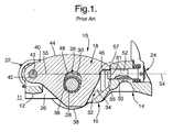
- FIG. 1 is a cross-sectional view of a prior art roller finger follower substantially as disclosed in US 6,755,167 B2, showing the slider tip engaged by the latch pin;
- FIG. 2 is a cross-sectional view of an improved roller finger follower in accordance with the invention, showing an angled latch pin channel and latch pin, wherein the slider tip is engaged by the latch pin in high-lift mode; and
- FIG. 3 is a cross-sectional view of the improved roller finger follower shown in FIG. 2, wherein the slider tip is disengaged from the latch pin in lost-motion (low-lift) mode.
- Referring to FIGS. 1 through 3,
prior art RFF 10 and improved RFF 10' are shown.Prior art RFF 10 is configured substantially as shown in incorporated US Patent No. 6,755,167, the details of which need not be repeated here. Sufficient detail, however, is provided to appreciate the improvement and benefit afforded by improved RFF 10' in accordance with the invention. - A roller finger follower such as
RFF 10 or RFF 10' is intended for use with aninternal combustion engine 11 comprising a camshaft configuration (shown in reference) having a central high-lift lobe flanked by a pair of low-lift lobes. The high lift lobe is either enabled, by latching of a central slider within the RFF, or disabled, by unlatching the central slider and allowing it to pivotably follow the high-lift lobe in lost motion. - As FIGS. 1 through 3
show RFF 10 and RFF 10' in longitudinal cross-section, some components and aspects are not shown, particularly those that are paired in the actual embodiments. Such pairings are indicated by *, and are fully disclosed in the incorporated reference. - For simplicity, the prior art and improved RFFs are discussed together in the following paragraphs wherein their construction is similar or identical. Following that, the novel differences are then disclosed independently.
- Referring to FIGS. 1 and 2, a
pallet end 12,12' ofRFF 10,10' is provided for engaging a valve stem (shown in reference) andsocket end 14,14' ofRFF 10,10' is provided for engaging a pivot point such as the hemispherical head of a hydraulic lash adjuster (shown in reference).RFF 10,10' includesbody assembly 16,16',slider arm assembly 18,18',spool roller assembly 20,20', lost motion springs* 22,22', andlatch assembly 24, 24'. -
Body assembly 16,16' includeselongate body 26,26' and roller bearings* 28,28' disposed in bearing orifices* 30,30'.Elongate body 26,26' includes aslider arm aperture 32,32' bounded by body side walls* 34,34' defining bearing orifices* 30,30' therethrough. The diameters of bearing orifices* 30,30' are sized to press-fittedly receive roller bearings* 28,28'. Across-shaft 36,36' is rotatably disposed in bearings* 28,28' and is supportive of rollers* 38,38 on the ends thereof for following the low-lift cam lobes. -
Slider arm assembly 18,18' includesslider arm 40,40' andslider shaft 42,42', havingaxes 43,43', for pivotably attachingarm 40,40' tobody 26,26'.Slider arm 40,40' definesslider surface 44,44' for following the high lift cam lobe,slider tip 46,46', and elongated rollershaft clearance aperture 48,48'. - In improved RFF 10' as shown in FIGS. 2 and 3, return spring 22' is a torsion spring, although other means of biasing slider arm 40', such as a compression spring may be employed as desired.
- The novel distinction between
prior art RFF 10 and improved RFF 10' lies in the orientation of theirrespective latching assemblies 24,24'.Socket end 14,14' ofbody 26,26' defines alatch channel 50,50' for receiving alatch pin 52,52'.Channel 50,50' andlatch pin 52,52' define alatch pin axis 54,54' and therefore a path along which the latch pin moves in engagingslider tip 46,46' to lock or unlock the slider between high and low lift positions. - In
prior art RFF 10,latch pin axis 54 is substantially perpendicular to, and passes through,pivot pin axis 43. Thusaxis 54 lies on aradius 55 of the rotational arc of slider arm 40 (i.e,axis 54 forms an includedangle 57 of 180° with an extension of radius 55), causingslider tip 46 to be traveling in a direction substantially orthogonal toaxis 54 at the point of engagement withlatch pin 52. - Because
pin 52 must extend fromchannel 50 to form such engagement, a bending moment is created innose portion 61 oflatch pin 52 about thedistal lip 56 ofchannel 50.Lip 56 cannot be extended to supportpin 52 and eliminate the bending moment because it would then interfere with the lost motion travel ofslider tip 46. As discussed previously, this relationship requires an undesirablylong channel 50 to supportpin 52 against the bending moment, and also allows forpin 52 to inadvertently engageslider tip 46 onsurface 44 when the locking pin is commanded to move outward after the slider is fully depressed by the associated cam lobe, thereby undesirably locking the slider tip in the fully-depressed valve-deactivation position (not shown). - Referring now to FIGS. 2 and 3, in improved RFF 10', latch pin axis 54' does not pass through pivot pin axis 43' and thus does not lie on a radius 55' of the rotational arc of slider arm 40' (i.e, axis 54' forms an included angle 57' of less than 180° with an extension of radius 55'), causing slider tip 46' to be traveling in a direction substantially non-orthogonal to axis 54' at the point of engagement with latch pin 52'. This relationship allows pin 52' to be fully supported by lip 56' during engagement by slider tip 46', thus eliminating any bending moment in nose portion 61' of latch pin 52' without interfering with the lost motion travel of slider tip 46'. An additional benefit of the just-described relationship is that pin 52' cannot inadvertently lock the slider in the full lost-motion position.
- Referring to FIG. 3, RFF 10' is shown in lost-motion position. Preferably, the outer end of slider 40' is formed as an
arcuate surface 60 centered on pin axis 43', and tip 46' is placed low enough onsurface 60 that latch pin 52' followssurface 60 throughout the motion of slider 40'. Thus, actuating latch pin 52' during the lost-motion cycle, as by providing pressurized oil tochamber 62 viaoil passage 64, cannot cause the latch pin to lock the slider tip in the lost-motion position; and further, when the pressure is removed and the slider is returned to the high-lift position by spring 22', the latch pin snaps automatically into the high-lift lock position as shown in FIG. 2. - As described above, the novel distinction of this invention lies in the orientation of
latch assembly 24 relative toslider assembly 18 and itspivotal axis 43. Therefore, while this invention has been described in reference to a spool type RFF, as shown in US Patent No. 6,755,167, the invention applies equally to other deactivation and multi-step RFFs including the prior art RFF having a non-rotatable roller shaft fixed to the body of the RFF, as described above. - While the invention has been described by reference to various specific embodiments, it should be understood that numerous changes may be made within the spirit and scope of the inventive concepts described. Accordingly, it is intended that the invention not be limited to the described embodiments, but will have full scope defined by the language of the following claims.
Claims (6)
- A roller finger follower (10') for use in conjunction with a cam shaft of an internal combustion engine, the camshaft having at least one first lobe and at least one second lobe, said roller finger follower comprising:a) an elongate body (16') including a first body end (12'), a second body end (14'), a slider arm aperture (32'), and a latch pin channel (50');b) a slider arm (40') disposed in said slider arm aperture (32') for engaging said first cam lobe and having a first end and a second end, said first end of said slider arm being mounted to said first body end for pivotal motion about a pivot axis (43'), and said second end of said slider arm defining a slider tip (46');c) at least one roller element (36', 38') rotatably associated with said elongate body for engaging said second cam lobe; andd) a latch pin (52') slidably disposed in said latch pin channel (50'), said latch pin having a latch pin axis (54') and having a nose section (61') for selectively engaging said slider tip (46'),
wherein an extension of a radius (55') of said slider arm (40') from said pivot axis (43') through said latch pin nose section (61') intersects said latch pin axis (54') at an included angle (57') of less than 180 degrees. - A roller finger follower (10') in accordance with Claim 1 wherein said first cam lobe is a high-lift lobe and said second cam lobe is a low-lift lobe.
- A roller finger follower (10') in accordance with Claim 1 wherein:said elongate body (16') further includes a first side member (34') and a second side member (34'), said side members defining coaxially disposed shaft orifices (30');said at least one roller element 36', 38') includes two rollers (38') operationally connected to a roller shaft (36'),wherein said roller shaft (36') is disposed in said shaft orifices (30').
- A roller finger follower (10') in accordance with Claim 3 wherein said roller shaft (36') is non-rotatably fixed to said elongate body (16').
- A roller finger follower (10') in accordance with Claim 3 wherein said roller shaft (36') is rotatably associated with said elongate body (16').
- An internal combustion engine (11) including a camshaft having high-lift and low-lift cam lobes, comprising a roller finger follower (10') for selectively adjusting the lift of an associated engine valve, wherein said roller finger follower includes,
an elongate body (16') having a first side member (34') and a second side member (34'), said members defining coaxially disposed shaft orifices (30'), a pallet end (12') and a socket end (14') interconnecting with said first and second side members to define a slider arm aperture (32'), and a latch pin channel (50'),
a slider arm (40') disposed in said slider arm aperture (50') for engaging said high-lift cam lobe and having a first end and a second end, said first end of said slider arm being mounted to said pallet end (12') of said body (16') for pivotal motion about a pivot axis (43'), and said second end defining a slider tip (46'),
a spool roller (36', 38') having a shaft (36') and at least one roller element (38') for engaging at least one of said low-lift cam lobes, said shaft (36') of said spool roller being disposed in said shaft orifices (30'), and
a latch pin (52') slidably disposed in said latch pin channel (50'), said latch pin having a latch pin axis (54') and having a nose section (61') for selectively engaging said slider tip (46'),
wherein an extension of a radius (55') of said slider arm (40') from said pivot axis (43') through said latch pin nose section (61') intersects said latch pin axis (54') at an included angle (57') of less than 180 degrees.
Applications Claiming Priority (1)
| Application Number | Priority Date | Filing Date | Title |
|---|---|---|---|
| US10/924,614 US6925978B1 (en) | 2004-08-24 | 2004-08-24 | Two-step roller finger cam follower having angled lock pin |
Publications (1)
| Publication Number | Publication Date |
|---|---|
| EP1630366A1 true EP1630366A1 (en) | 2006-03-01 |
Family
ID=34808742
Family Applications (1)
| Application Number | Title | Priority Date | Filing Date |
|---|---|---|---|
| EP05076819A Withdrawn EP1630366A1 (en) | 2004-08-24 | 2005-08-05 | Two-step roller cam follower having angled lock pin |
Country Status (2)
| Country | Link |
|---|---|
| US (1) | US6925978B1 (en) |
| EP (1) | EP1630366A1 (en) |
Cited By (9)
| Publication number | Priority date | Publication date | Assignee | Title |
|---|---|---|---|---|
| DE102006023772A1 (en) * | 2006-05-20 | 2007-11-22 | Schaeffler Kg | Switchable drag lever for a valve train of an internal combustion engine |
| DE102006046574A1 (en) * | 2006-09-30 | 2008-04-03 | Schaeffler Kg | Switched lever to operate motor valves has a lost motion coil spring, at the axis floating within drillings in inner/outer levers, with coils pressed against the axis |
| DE102006057894A1 (en) * | 2006-12-08 | 2008-06-12 | Schaeffler Kg | Switchable drag lever of a valve train of an internal combustion engine |
| DE102006057895A1 (en) * | 2006-12-08 | 2008-06-12 | Schaeffler Kg | Switchable drag lever of a valve train of an internal combustion engine |
| DE102006061296A1 (en) * | 2006-12-22 | 2008-06-26 | Schaeffler Kg | Switchable drag lever for a valve train of an internal combustion engine u. Method for mounting a switchable rocker arm |
| DE102009041367A1 (en) | 2009-09-11 | 2011-03-24 | Schaeffler Technologies Gmbh & Co. Kg | Assembly for valve train of internal combustion engine, comprises switching cam lever, which is fastened at end of head of supporting element by swiveling joint |
| DE102009041368A1 (en) | 2009-09-11 | 2011-03-24 | Schaeffler Technologies Gmbh & Co. Kg | Assembly for valve train of internal combustion engine, comprises switching cam lever, which is fastened at end of head of supporting element by swiveling joint |
| DE102010006420A1 (en) | 2010-02-01 | 2011-08-04 | Schaeffler Technologies GmbH & Co. KG, 91074 | Component for valve train of combustion engine, has rocker finger tied over pivot at end on head of support unit, which has switching rocker finger made from two arms |
| EP3536916A1 (en) * | 2018-03-07 | 2019-09-11 | OTICS Corporation | Variable valve mechanism of internal combustion engine |
Families Citing this family (22)
| Publication number | Priority date | Publication date | Assignee | Title |
|---|---|---|---|---|
| US7093572B2 (en) * | 2003-12-19 | 2006-08-22 | Delphi Technologies, Inc. | Roller finger follower assembly for valve deactivation |
| EP1725744B1 (en) | 2004-03-03 | 2008-05-28 | Timken US Corporation | Switching finger follower assembly |
| EP2317084A1 (en) * | 2005-09-16 | 2011-05-04 | Koyo Bearings USA, LLC | Switching finger follower assembly |
| US7278384B2 (en) * | 2005-09-30 | 2007-10-09 | Delphi Technologies, Inc. | Timing mechanism for a switchable two-step roller finger follower |
| DE102006013566A1 (en) * | 2006-03-24 | 2007-09-27 | Schaeffler Kg | Switchable lever for a valve drive of an internal combustion engine comprises an outer lever having a recess for an inner lever arranged on an axle which is arranged on one end of the outer lever |
| US8132551B2 (en) * | 2006-04-21 | 2012-03-13 | Schaeffler Kg | Switchable cam follower of a valve train assembly of an internal combustion engine |
| US7721694B2 (en) * | 2006-07-20 | 2010-05-25 | Delphi Technologies, Inc. | Lock pin retention plug for a two-step rocker arm assembly |
| US20080283003A1 (en) | 2007-05-16 | 2008-11-20 | Hendriksma Nick J | Two-step roller finger cam follower |
| US7798113B2 (en) * | 2007-06-20 | 2010-09-21 | Delphi Technologies, Inc. | Two-step roller finger cam follower assembly having a follower travel limiter |
| DE102007029465A1 (en) * | 2007-06-26 | 2009-01-08 | Schaeffler Kg | Switchable drag lever of a valve train of an internal combustion engine |
| KR100861306B1 (en) * | 2007-06-26 | 2008-10-01 | 주식회사 하이닉스반도체 | Wiring of a semiconductor device and its formation method |
| US20090126527A1 (en) * | 2007-11-21 | 2009-05-21 | Bauman William D | Bearing design for a roller finger follower |
| US9534511B2 (en) * | 2014-05-29 | 2017-01-03 | Delphi Technologies, Inc. | Switchable rocker arm with improved switching response time |
| CN104061039A (en) * | 2014-06-30 | 2014-09-24 | 绵阳富临精工机械股份有限公司 | Engine valve lift two-stage variable adjustment pressure lever assembly |
| USD833482S1 (en) | 2015-07-13 | 2018-11-13 | Eaton Corporation | Rocker arm |
| USD791190S1 (en) | 2015-07-13 | 2017-07-04 | Eaton Corporation | Rocker arm assembly |
| USD830414S1 (en) * | 2015-12-10 | 2018-10-09 | Eaton S.R.L. | Roller rocker arm of an engine |
| DE102015225727A1 (en) * | 2015-12-17 | 2017-07-06 | Bayerische Motoren Werke Aktiengesellschaft | Decompression device for a reciprocating internal combustion engine |
| JP6736484B2 (en) | 2017-01-10 | 2020-08-05 | 株式会社オティックス | Variable valve mechanism for internal combustion engine |
| US10054014B1 (en) | 2017-02-20 | 2018-08-21 | Delphi Technologies Ip Limited | Latching arrangement for switchable rocker arm |
| US10871087B2 (en) * | 2019-01-29 | 2020-12-22 | Delphi Technologies Ip Limited | Switchable rocker arm |
| US10900385B2 (en) | 2019-01-29 | 2021-01-26 | Delphi Technologies Ip Limited | Switchable rocker arm |
Citations (6)
| Publication number | Priority date | Publication date | Assignee | Title |
|---|---|---|---|---|
| US4612884A (en) * | 1984-07-24 | 1986-09-23 | Honda Giken Kogyo Kabushiki Kaisha | Valve operating and interrupting mechanism for internal combustion engine |
| EP0442460A1 (en) * | 1990-02-16 | 1991-08-21 | FERRARI S.p.A. | Variable timing system, particularly for an internal combustion engine |
| US5251586A (en) * | 1991-03-29 | 1993-10-12 | Fuji Jukogyo Kabushiki Kaisha | Valve mechanism for an internal combustion engine |
| US5544626A (en) * | 1995-03-09 | 1996-08-13 | Ford Motor Company | Finger follower rocker arm with engine valve deactivator |
| US20030111031A1 (en) * | 2001-12-17 | 2003-06-19 | Hendricksma Nick J. | Variable valve actuation assembly for an internal combustion engine |
| US20030159666A1 (en) * | 2002-02-26 | 2003-08-28 | Krieg John J. | Two-step roller finger cam follower having spool-shaped low-lift roller |
Family Cites Families (2)
| Publication number | Priority date | Publication date | Assignee | Title |
|---|---|---|---|---|
| US4611558A (en) * | 1984-10-12 | 1986-09-16 | Toyota Jidosha Kabushiki Kaisha | Valve actuating apparatus in internal combustion engine |
| US6318318B1 (en) * | 2001-05-15 | 2001-11-20 | Ford Global Technologies, Inc. | Rocker arm assembly |
-
2004
- 2004-08-24 US US10/924,614 patent/US6925978B1/en not_active Expired - Lifetime
-
2005
- 2005-08-05 EP EP05076819A patent/EP1630366A1/en not_active Withdrawn
Patent Citations (7)
| Publication number | Priority date | Publication date | Assignee | Title |
|---|---|---|---|---|
| US4612884A (en) * | 1984-07-24 | 1986-09-23 | Honda Giken Kogyo Kabushiki Kaisha | Valve operating and interrupting mechanism for internal combustion engine |
| EP0442460A1 (en) * | 1990-02-16 | 1991-08-21 | FERRARI S.p.A. | Variable timing system, particularly for an internal combustion engine |
| US5251586A (en) * | 1991-03-29 | 1993-10-12 | Fuji Jukogyo Kabushiki Kaisha | Valve mechanism for an internal combustion engine |
| US5544626A (en) * | 1995-03-09 | 1996-08-13 | Ford Motor Company | Finger follower rocker arm with engine valve deactivator |
| US20030111031A1 (en) * | 2001-12-17 | 2003-06-19 | Hendricksma Nick J. | Variable valve actuation assembly for an internal combustion engine |
| US20030159666A1 (en) * | 2002-02-26 | 2003-08-28 | Krieg John J. | Two-step roller finger cam follower having spool-shaped low-lift roller |
| US6755167B2 (en) | 2002-02-26 | 2004-06-29 | Delphi Technologies, Inc. | Two-step roller finger cam follower having spool-shaped low-lift roller |
Cited By (10)
| Publication number | Priority date | Publication date | Assignee | Title |
|---|---|---|---|---|
| DE102006023772A1 (en) * | 2006-05-20 | 2007-11-22 | Schaeffler Kg | Switchable drag lever for a valve train of an internal combustion engine |
| DE102006046574A1 (en) * | 2006-09-30 | 2008-04-03 | Schaeffler Kg | Switched lever to operate motor valves has a lost motion coil spring, at the axis floating within drillings in inner/outer levers, with coils pressed against the axis |
| DE102006046574B4 (en) * | 2006-09-30 | 2017-12-28 | Schaeffler Technologies AG & Co. KG | Switchable drag lever of a valve train of an internal combustion engine |
| DE102006057894A1 (en) * | 2006-12-08 | 2008-06-12 | Schaeffler Kg | Switchable drag lever of a valve train of an internal combustion engine |
| DE102006057895A1 (en) * | 2006-12-08 | 2008-06-12 | Schaeffler Kg | Switchable drag lever of a valve train of an internal combustion engine |
| DE102006061296A1 (en) * | 2006-12-22 | 2008-06-26 | Schaeffler Kg | Switchable drag lever for a valve train of an internal combustion engine u. Method for mounting a switchable rocker arm |
| DE102009041367A1 (en) | 2009-09-11 | 2011-03-24 | Schaeffler Technologies Gmbh & Co. Kg | Assembly for valve train of internal combustion engine, comprises switching cam lever, which is fastened at end of head of supporting element by swiveling joint |
| DE102009041368A1 (en) | 2009-09-11 | 2011-03-24 | Schaeffler Technologies Gmbh & Co. Kg | Assembly for valve train of internal combustion engine, comprises switching cam lever, which is fastened at end of head of supporting element by swiveling joint |
| DE102010006420A1 (en) | 2010-02-01 | 2011-08-04 | Schaeffler Technologies GmbH & Co. KG, 91074 | Component for valve train of combustion engine, has rocker finger tied over pivot at end on head of support unit, which has switching rocker finger made from two arms |
| EP3536916A1 (en) * | 2018-03-07 | 2019-09-11 | OTICS Corporation | Variable valve mechanism of internal combustion engine |
Also Published As
| Publication number | Publication date |
|---|---|
| US6925978B1 (en) | 2005-08-09 |
Similar Documents
| Publication | Publication Date | Title |
|---|---|---|
| US6925978B1 (en) | Two-step roller finger cam follower having angled lock pin | |
| US6668779B2 (en) | Two-step finger follower rocker arm assembly | |
| US6966291B1 (en) | Latch timing mechanism for a two-step roller finger cam follower | |
| US10196943B2 (en) | Valve train assembly | |
| US6615782B1 (en) | Two-step finger follower rocker arm | |
| US20080283003A1 (en) | Two-step roller finger cam follower | |
| US6691657B2 (en) | Two-step finger follower rocker arm | |
| US6668775B2 (en) | Lock-pin cartridge for a two-step finger follower rocker arm | |
| US7798113B2 (en) | Two-step roller finger cam follower assembly having a follower travel limiter | |
| US6997152B2 (en) | Lock-pin cartridge for a valve deactivation rocker arm assembly | |
| US20070193543A1 (en) | Valve deactivation device | |
| US20090223473A1 (en) | Rocker arm assembly | |
| JP2007526423A (en) | Switchable finger follower assembly | |
| CN115667676A (en) | rocker arm | |
| US20060102118A1 (en) | Valve-actuating for internal combustion engine | |
| KR20180041685A (en) | Switching rocker arms for internal exhaust gas recirculation | |
| EP1544423A2 (en) | Roller finger follower assembly for valve deactivation | |
| US20190085732A1 (en) | Switching rocker arm | |
| EP1934436B1 (en) | Switching finger follower assembly | |
| EP3628832A1 (en) | Switchable rocker arm |
Legal Events
| Date | Code | Title | Description |
|---|---|---|---|
| PUAI | Public reference made under article 153(3) epc to a published international application that has entered the european phase |
Free format text: ORIGINAL CODE: 0009012 |
|
| AK | Designated contracting states |
Kind code of ref document: A1 Designated state(s): AT BE BG CH CY CZ DE DK EE ES FI FR GB GR HU IE IS IT LI LT LU LV MC NL PL PT RO SE SI SK TR |
|
| AX | Request for extension of the european patent |
Extension state: AL BA HR MK YU |
|
| 17P | Request for examination filed |
Effective date: 20060901 |
|
| 17Q | First examination report despatched |
Effective date: 20061006 |
|
| AKX | Designation fees paid |
Designated state(s): AT BE BG CH CY CZ DE DK EE ES FI FR GB GR HU IE IS IT LI LT LU LV MC NL PL PT RO SE SI SK TR |
|
| STAA | Information on the status of an ep patent application or granted ep patent |
Free format text: STATUS: THE APPLICATION IS DEEMED TO BE WITHDRAWN |
|
| 18D | Application deemed to be withdrawn |
Effective date: 20081107 |