EP1630353A2 - Internally cooled gas turbine aerofoil - Google Patents
Internally cooled gas turbine aerofoil Download PDFInfo
- Publication number
- EP1630353A2 EP1630353A2 EP05255153A EP05255153A EP1630353A2 EP 1630353 A2 EP1630353 A2 EP 1630353A2 EP 05255153 A EP05255153 A EP 05255153A EP 05255153 A EP05255153 A EP 05255153A EP 1630353 A2 EP1630353 A2 EP 1630353A2
- Authority
- EP
- European Patent Office
- Prior art keywords
- aerofoil
- blade
- wall
- carrying members
- load carrying
- Prior art date
- Legal status (The legal status is an assumption and is not a legal conclusion. Google has not performed a legal analysis and makes no representation as to the accuracy of the status listed.)
- Granted
Links
- 238000001816 cooling Methods 0.000 claims abstract description 25
- 238000009826 distribution Methods 0.000 claims abstract description 9
- 238000012546 transfer Methods 0.000 claims abstract description 6
- 230000000630 rising effect Effects 0.000 claims description 2
- 238000013461 design Methods 0.000 description 16
- 239000002184 metal Substances 0.000 description 14
- 239000000463 material Substances 0.000 description 9
- 239000000919 ceramic Substances 0.000 description 7
- 239000012809 cooling fluid Substances 0.000 description 5
- 230000000694 effects Effects 0.000 description 5
- 238000004519 manufacturing process Methods 0.000 description 4
- 238000000034 method Methods 0.000 description 4
- XLYOFNOQVPJJNP-UHFFFAOYSA-N water Substances O XLYOFNOQVPJJNP-UHFFFAOYSA-N 0.000 description 3
- 230000002411 adverse Effects 0.000 description 2
- 230000009286 beneficial effect Effects 0.000 description 2
- 230000008901 benefit Effects 0.000 description 2
- 238000005266 casting Methods 0.000 description 2
- 239000002826 coolant Substances 0.000 description 2
- 238000005192 partition Methods 0.000 description 2
- 239000000956 alloy Substances 0.000 description 1
- 229910045601 alloy Inorganic materials 0.000 description 1
- 238000005452 bending Methods 0.000 description 1
- 238000004891 communication Methods 0.000 description 1
- 230000007423 decrease Effects 0.000 description 1
- 230000001419 dependent effect Effects 0.000 description 1
- 230000001627 detrimental effect Effects 0.000 description 1
- 238000011161 development Methods 0.000 description 1
- 230000018109 developmental process Effects 0.000 description 1
- 238000005516 engineering process Methods 0.000 description 1
- 238000000605 extraction Methods 0.000 description 1
- 238000005495 investment casting Methods 0.000 description 1
- 238000005259 measurement Methods 0.000 description 1
- 238000002844 melting Methods 0.000 description 1
- 230000008018 melting Effects 0.000 description 1
- 238000000465 moulding Methods 0.000 description 1
- 230000001105 regulatory effect Effects 0.000 description 1
- 238000004904 shortening Methods 0.000 description 1
- 239000007787 solid Substances 0.000 description 1
- 238000000638 solvent extraction Methods 0.000 description 1
- 238000003466 welding Methods 0.000 description 1
Images

Classifications
-
- F—MECHANICAL ENGINEERING; LIGHTING; HEATING; WEAPONS; BLASTING
- F01—MACHINES OR ENGINES IN GENERAL; ENGINE PLANTS IN GENERAL; STEAM ENGINES
- F01D—NON-POSITIVE DISPLACEMENT MACHINES OR ENGINES, e.g. STEAM TURBINES
- F01D5/00—Blades; Blade-carrying members; Heating, heat-insulating, cooling or antivibration means on the blades or the members
- F01D5/12—Blades
- F01D5/14—Form or construction
- F01D5/18—Hollow blades, i.e. blades with cooling or heating channels or cavities; Heating, heat-insulating or cooling means on blades
- F01D5/187—Convection cooling
- F01D5/188—Convection cooling with an insert in the blade cavity to guide the cooling fluid, e.g. forming a separation wall
-
- F—MECHANICAL ENGINEERING; LIGHTING; HEATING; WEAPONS; BLASTING
- F01—MACHINES OR ENGINES IN GENERAL; ENGINE PLANTS IN GENERAL; STEAM ENGINES
- F01D—NON-POSITIVE DISPLACEMENT MACHINES OR ENGINES, e.g. STEAM TURBINES
- F01D5/00—Blades; Blade-carrying members; Heating, heat-insulating, cooling or antivibration means on the blades or the members
- F01D5/12—Blades
- F01D5/14—Form or construction
- F01D5/147—Construction, i.e. structural features, e.g. of weight-saving hollow blades
-
- F—MECHANICAL ENGINEERING; LIGHTING; HEATING; WEAPONS; BLASTING
- F01—MACHINES OR ENGINES IN GENERAL; ENGINE PLANTS IN GENERAL; STEAM ENGINES
- F01D—NON-POSITIVE DISPLACEMENT MACHINES OR ENGINES, e.g. STEAM TURBINES
- F01D5/00—Blades; Blade-carrying members; Heating, heat-insulating, cooling or antivibration means on the blades or the members
- F01D5/12—Blades
- F01D5/14—Form or construction
- F01D5/18—Hollow blades, i.e. blades with cooling or heating channels or cavities; Heating, heat-insulating or cooling means on blades
-
- F—MECHANICAL ENGINEERING; LIGHTING; HEATING; WEAPONS; BLASTING
- F01—MACHINES OR ENGINES IN GENERAL; ENGINE PLANTS IN GENERAL; STEAM ENGINES
- F01D—NON-POSITIVE DISPLACEMENT MACHINES OR ENGINES, e.g. STEAM TURBINES
- F01D5/00—Blades; Blade-carrying members; Heating, heat-insulating, cooling or antivibration means on the blades or the members
- F01D5/12—Blades
- F01D5/14—Form or construction
- F01D5/18—Hollow blades, i.e. blades with cooling or heating channels or cavities; Heating, heat-insulating or cooling means on blades
- F01D5/186—Film cooling
-
- F—MECHANICAL ENGINEERING; LIGHTING; HEATING; WEAPONS; BLASTING
- F05—INDEXING SCHEMES RELATING TO ENGINES OR PUMPS IN VARIOUS SUBCLASSES OF CLASSES F01-F04
- F05D—INDEXING SCHEME FOR ASPECTS RELATING TO NON-POSITIVE-DISPLACEMENT MACHINES OR ENGINES, GAS-TURBINES OR JET-PROPULSION PLANTS
- F05D2260/00—Function
- F05D2260/20—Heat transfer, e.g. cooling
- F05D2260/231—Preventing heat transfer
-
- Y—GENERAL TAGGING OF NEW TECHNOLOGICAL DEVELOPMENTS; GENERAL TAGGING OF CROSS-SECTIONAL TECHNOLOGIES SPANNING OVER SEVERAL SECTIONS OF THE IPC; TECHNICAL SUBJECTS COVERED BY FORMER USPC CROSS-REFERENCE ART COLLECTIONS [XRACs] AND DIGESTS
- Y02—TECHNOLOGIES OR APPLICATIONS FOR MITIGATION OR ADAPTATION AGAINST CLIMATE CHANGE
- Y02T—CLIMATE CHANGE MITIGATION TECHNOLOGIES RELATED TO TRANSPORTATION
- Y02T50/00—Aeronautics or air transport
- Y02T50/60—Efficient propulsion technologies, e.g. for aircraft
Definitions
- the invention relates to internally cooled aerofoils.
- the surface temperature of the aerofoils in the high pressure turbine of a gas turbine engine can reach the melting point of the alloy of which they are constructed. Hence heat is extracted by passing cooling air through passages formed in the interior or in the walls of the aerofoil.
- Known methods of casting internally cooled turbine aerofoils use ceramic cores that have been manufactured in a die. Consequently the shapes of the internal webs that define the internal cooling passages are constrained by the requirements for die draw/withdrawal angles.
- the webs of the internal structure of aerofoils containing multiple cooling passages have been made thinner either in the middle or on one side of the blade, depending on the complexity of the die. Examples of internal structures of this kind are illustrated at Figures 1 and 2.
- Japanese Patent No JP 60135605 entitled “Turbine Blade Cooling” published in 1985 disclosed an internally cooled turbine blade in which rib walls partitioning flow passages in the interior of the blade are made into convex forms.
- This convex form reduces the cross-sectional area of the flow passage, compared to the same blade in which the partition walls are not convex, resulting in increased flow speed in the passage and increased coefficient of heat transfer by convection.
- the cross-section of the passages and therefore also the ribs is maintained constant over the length of the passages, ie the height of the blade regardless of the effect on mass distribution in the structure of the blade. Notwithstanding increased heat extraction, increased mass in a rotating component at high radius will adversely affect the creep resistance of the blade and this may be a limiting factor in blade life. This might be the case where engine weight is important as in an aircraft propulsion engine.
- Japanese Patent No JP 61205301 entitled “Gas Turbine Blade” teaches an arrangement to dissipate the unevenness in the temperature of a water cooled gas turbine blade in which the sectional area of the cooling passages is smaller in the mid-height part of the blade than in the root and tip regions.
- the partition walls between flow passages are provided with projecting parts, or ribs, to enhance heat transfer.
- Such an arrangement is designed only with regard to the distribution of temperature in the blade structure and the transfer of heat from the structure to the cooling fluid. It suffers a drawback of increased mass distribution in the structure of the blade especially towards the tip region which, as before, has an adverse effect on the creep-life of the blade.
- the design of the cross-section of a turbine blade is governed by the permitted stress in the material and by the size of the core passages required for cooling purposes.
- the operating temperatures of the blades dictate the need to cool them internally, in the case of aircraft propulsion engines that means using cooling air derived from the engine itself.
- system weight is not critical, such as in land-based or marine power systems, other heavier cooling such as water or steam may be used.
- cooling flow is detrimental to overall engine performance and to mitigate that the flow is regulated very carefully and material choice and internal blade design is very important.
- the blades glow red-hot during engine running they must retain sufficient strength to carry high centrifugal loads due to their rotation and the bending loads exerted by the force of the gas stream.
- creep life is a major factor dictating the finite useful life limit of a turbine blade.
- creep increases, or creep resistance decreases, with higher blade operating temperatures.
- weight is also important so a blade with poor weight distribution will exhibit increased creep shortening its useful life.
- a primary objective of the present invention is to balance these factors to the benefit of blade life.
- an internally cooled gas turbine aerofoil comprising foot adapted for mounting on a disc, and rising in a radial direction above said foot a hollow aerofoil profiled section consisting of an outer wall defining pressure and suction surfaces, wherein the outer wall is supported by an internal structure including load carrying members carried by or formed integrally with said foot that divide the interior cavity of the aerofoil section into a plurality of cooling passages, the dimensions of the internal structure are chosen with respect to inward heat flow during operation to tend to reduce heat transfer from the outer wall to the load carrying members and with respect to mass distribution in the structure to reduce centrifugal forces during operation.
- the load carrying members are thinnest adjacent the inner surfaces of the outer wall at least up to about mid-height of the blade and thickest about mid-way between the pressure and suction surfaces.
- FIG. 1 and 2 of the accompanying drawings illustrate mid-height cross-sections of two known turbine blade aerofoils.
- the turbine aerofoil generally indicated at 2, has internal cooling arrangements comprising a plurality of chambers formed by internal webs 4, 6 & 8 and connected in flow sequence by passages (not shown) located towards the base and tip of the aerofoil.
- passages not shown
- FIG. 1 and 2 of the accompanying drawings illustrate mid-height cross-sections of two known turbine blade aerofoils.
- the turbine aerofoil generally indicated at 2
- FIG. 1 and 2 of the accompanying drawings illustrate mid-height cross-sections of two known turbine blade aerofoils.
- the turbine aerofoil generally indicated at 2
- FIG. 1 and 2 of the accompanying drawings illustrate mid-height cross-sections of two known turbine blade aerofoils.
- FIG. 1 and 2 of the accompanying drawings illustrate mid-height cross-sections of two known turbine blade aerofoils.
- the turbine aerofoil generally indicated at
- Cooling fluid is employed to remove heat from the metal structure of the aerofoil through the surfaces over which it passes.
- the outer walls reach the highest temperatures and heat flows from them into the internal webs. Heat is lost from these webs according to, amongst other things, the excess temperature of the metal over the cooling fluid.
- the operational life of the metal structure is also dependent upon the time it spends at the highest temperatures.
- the invention is concerned with the use of air as the cooling fluid; although it is known, for example in land-based and marine propulsion engines, to use water and steam. The principles embodied by the present invention continue to apply in such circumstances.
- the thickest parts of the load carrying members comprising the internal structure are located about mid-way between the pressure and suction surfaces of the blade and up to about mid-height, and the said members are thinnest adjacent the inner surfaces of the outer wall. Consequently heat from the outer wall of the turbine blade flows into the internal support structure through the interface between them. Reduction of the area of this interface has the effect of reducing the amount of heat passing into the internal support structure.
- Detailed measurements of temperature distribution in the aerofoil internal support structure have indicated that the shape of the cold webs does not have a significant effect on the cooling efficiency of the system. That is, for a given cross-sectional area of a cooling passage, the perimeter (and hence hydraulic diameter) may change a little. However, reducing the mean temperature of the support structure significantly improves the creep life of the component.
- This design principle may be expressed as positioning more of the metal (or material) towards the centre of the cooled aerofoil structure relative to its periphery thus achieving a lower mean metal temperature. This increases cooling effectiveness for a given coolant condition / mass flow. In the described embodiments the creep life of the blades has been improved at the same operating temperature using the same cooled surface area, cooling passage cross-section area and cooling fluid velocity.
- a reduced mean metal temperature increases the load carrying capacity of the aerofoil structure.
- a blade structure designed according to this principle has a greater creep life.
- the same mean metal temperature may be obtained using less coolant flow, or the operating temperature may be increased for the same blade life.
- the cross-sections of the support members have a profile that is tapered towards the outer aerofoil wall.
- the support members are tapered towards the outer wall on both the pressure and suction sides of the aerofoil.
- the internal structure is reduced in mass towards the blade tip compared to the blade foot.
- foot is used here and in the claims as a generic reference to that portion of a blade by which it is carried in or attached to the circumference of the rotor disc.
- foot may be interpreted broadly for example as comprising a conventional fir-tree root, as in the example described below, as a root having a different profile form, or as a stub section by which the blade is welded to the disc periphery for instance by friction welding.
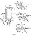
- FIG. 3 an internally cooled, shroudless gas turbine blade embodying the present invention is illustrated in perspective view together with three cross-section views at the root, mid-height and tip regions.
- the blade comprises an outer wall 10 of aerofoil-shaped profile, having pressure and suction surfaces 14, 16 as before.
- the root 24 is adapted for mounting on the periphery of a disc (not shown) in a slot of corresponding form.
- the fir-tree root is exemplary only and other root forms may be utilised as preferred.
- the aerofoil shaped section 20, the root 24 and the platform 22 are cast integrally using an investment casting process.
- the internal cooling passages 28, 30, 32 and 34 are formed using a complex, soluble ceramic core suspended inside the ceramic mould so that the spaces between the core parts form the members of the internal supporting structure.
- air entry orifices 36 are formed in a shank part 25 of root 24.
- the orifices 36 are formed in the base of the root section 24.
- the outer wall 10 is supported by an internal structure consisting of internal load carrying webs or members 36, 38 and 40 carried by, or preferably formed integrally with, the root 24. These webs may extend the full height of the blade integrally from the root 24 towards the tip of the blade. But because the mass of the blade is distributed over its height the supporting structure does not need to have as great a load carrying capacity at the tip as it does at the root. Thus the strength and therefore the dimensions of the individual members 36, 38, 40 of the supporting structure may be reduced from blade root to blade tip. Typically the full dimensions of the load carrying members 36, 38, 40 are maintained form the root up to about half the height of the blade and tapered from about mid-height in the radial direction. In the illustrated example this will be apparent by comparing the dimension in the cross-sections included in Figure 3. The dimensions of members 36, 38, 40 are substantially the same in the root section A and the mid section B. But, by comparison the same members have reduced dimensions in tip section C.
- the dimensions of the load carrying members 36, 38, 40 are tapered in the radial direction from about the root section C. In that case the dimensions of the members progressively reduces with height and are less in the mid section, and further reduced in the tip section.
- the support members 36, 38, 40 contact the inner surface of the outer wall 10 along their length, ie the height of the blade, and divide the interior of the aerofoil into the cooling chambers 28, 30, 32, 34.
- the dimensions of the members 36, 38, 40 are thinnest adjacent the inner surfaces 42, 44 of the suction and pressure surfaces 14, 16 respectively, and are thickest towards the centre region of the aerofoil approximately mid-way between the pressure and suction surfaces.
- the load carrying members 36, 38, 40 each have a straight-sided profile in which reach their thinnest or narrowest points adjacent the inner surfaces of the outer wall 10.
- the cross-section areas of the cooling passages 28, 30, 32, 34 remain substantially constant with radial height above the root portion.
- the cross-section dimensions of a turbine blade generally reduce with increasing radial height above the platform, and in this' instance the reduction is achieved through reduction in the dimensions of the metal parts, especially the support members 36, 38, 40.
- Advantage may be taken in this arrangement to increase the area in a given cooling arrangement of the inner surface 42, 44 of the outer wall 10 exposed to the cooling air thereby contributing, amongst other factors, to improving the efficiency with which heat can be removed from the hot external wall 10.
- the load carrying members may have a curved, blended profile towards their thinnest points adjacent the inner surfaces of the outer wall.
- the dimension of the centre region of one or more of the members may be increased to accommodate extra-thick portions, which extend the full height of the webs.
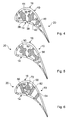
- One such portion is depicted at 46 towards the middle of the cross-section of the web 38 in Figure 4 representing a cross-section in a lower part of a blade between the root and mid-height sections corresponding to the sections A and B in Figure 3.
- the web is wider, that is lengthened in the chordal direction in the centre of the blade in order to increase its load-carrying capacity.
- the shape of the widened part of such a web may be chosen for best effect in the particular aerofoil design, the shape of the webs is not a feature of the invention itself.
- the important element is that a greater proportion of the mass of the web is positioned away from the hot external wall 10 by extra material added at the coldest part of the web to increase the beneficial effect of cooler load-carrying metal.
- the example of Figure 5 comprises three webs 50, 52 and 54 arranged much as in the previous design of Figure 3.
- the central parts are enlarged to increase their load ⁇ carrying capacity to the extent that two adjacent webs 52 and 54 touch.
- the central parts may be enlarged until they merge, depending on manufacturing constraints, to form an integral connecting the two adjacent webs.
- the material is distributed to ensure that the "width" of the cold webs are wider away from the external walls and thinner on the external walls.
- the cool material is distributed more effectively by having an additional cold web.
- the internal structure comprises parallel-sided internal webs 60, 62 and 64 located in the same positions as before.
- An additional load-carrying member 66 which extends form the root section towards the aerofoil tip, is disposed in the coolest part of the aerofoil interior.
- the member 66 is linked to the adjacent webs 60, 62 by walls 68, 70 and to the outer wall by a further wall 72 to ensure that load is transferred between said additional web 66 and the rest of the aerofoil.
- three linking walls are shown for illustrative purposes only. It may be appropriate to use one or more of these to link to one or more of the external surfaces and/or one or more of the internal cold webs.
- the webs may be formed with an enlarged central region, as previously described above.
Landscapes
- Engineering & Computer Science (AREA)
- Mechanical Engineering (AREA)
- General Engineering & Computer Science (AREA)
- Architecture (AREA)
- Turbine Rotor Nozzle Sealing (AREA)
Abstract
Description
- The invention relates to internally cooled aerofoils.
- In particular it concerns the design of the internal structure of an internally cooled turbine aerofoil for a gas turbine propulsion engine.
- The surface temperature of the aerofoils in the high pressure turbine of a gas turbine engine can reach the melting point of the alloy of which they are constructed. Hence heat is extracted by passing cooling air through passages formed in the interior or in the walls of the aerofoil. Known methods of casting internally cooled turbine aerofoils use ceramic cores that have been manufactured in a die. Consequently the shapes of the internal webs that define the internal cooling passages are constrained by the requirements for die draw/withdrawal angles. The webs of the internal structure of aerofoils containing multiple cooling passages have been made thinner either in the middle or on one side of the blade, depending on the complexity of the die. Examples of internal structures of this kind are illustrated at Figures 1 and 2.
- These designs suffer a drawback in that the shape of the internal webs forming the internal support structure for the aerofoil outer wall have been optimised for the ease of manufacture of the ceramic core or the aerofoil rather than for maximum aerofoil life.
- Japanese Patent No JP 60135605 entitled "Turbine Blade Cooling" published in 1985 disclosed an internally cooled turbine blade in which rib walls partitioning flow passages in the interior of the blade are made into convex forms. This convex form reduces the cross-sectional area of the flow passage, compared to the same blade in which the partition walls are not convex, resulting in increased flow speed in the passage and increased coefficient of heat transfer by convection. The cross-section of the passages and therefore also the ribs is maintained constant over the length of the passages, ie the height of the blade regardless of the effect on mass distribution in the structure of the blade. Notwithstanding increased heat extraction, increased mass in a rotating component at high radius will adversely affect the creep resistance of the blade and this may be a limiting factor in blade life. This might be the case where engine weight is important as in an aircraft propulsion engine.
- Japanese Patent No JP 61205301 entitled "Gas Turbine Blade" teaches an arrangement to dissipate the unevenness in the temperature of a water cooled gas turbine blade in which the sectional area of the cooling passages is smaller in the mid-height part of the blade than in the root and tip regions. In addition the partition walls between flow passages are provided with projecting parts, or ribs, to enhance heat transfer. Such an arrangement is designed only with regard to the distribution of temperature in the blade structure and the transfer of heat from the structure to the cooling fluid. It suffers a drawback of increased mass distribution in the structure of the blade especially towards the tip region which, as before, has an adverse effect on the creep-life of the blade.
- The design of the cross-section of a turbine blade, that is the internal structure inside the envelope of the outer wall, is governed by the permitted stress in the material and by the size of the core passages required for cooling purposes. The operating temperatures of the blades dictate the need to cool them internally, in the case of aircraft propulsion engines that means using cooling air derived from the engine itself. Where system weight is not critical, such as in land-based or marine power systems, other heavier cooling such as water or steam may be used. However, cooling flow is detrimental to overall engine performance and to mitigate that the flow is regulated very carefully and material choice and internal blade design is very important. Although the blades glow red-hot during engine running they must retain sufficient strength to carry high centrifugal loads due to their rotation and the bending loads exerted by the force of the gas stream. Over a period of time in use the length of a turbine blade slowly but inevitably increases ― a phenomenon known as creep. Thus, creep life is a major factor dictating the finite useful life limit of a turbine blade. Generally creep increases, or creep resistance decreases, with higher blade operating temperatures. But at a given operating temperature weight is also important so a blade with poor weight distribution will exhibit increased creep shortening its useful life. A primary objective of the present invention is to balance these factors to the benefit of blade life.
- According to the invention an internally cooled gas turbine aerofoil comprising foot adapted for mounting on a disc, and rising in a radial direction above said foot a hollow aerofoil profiled section consisting of an outer wall defining pressure and suction surfaces, wherein the outer wall is supported by an internal structure including load carrying members carried by or formed integrally with said foot that divide the interior cavity of the aerofoil section into a plurality of cooling passages, the dimensions of the internal structure are chosen with respect to inward heat flow during operation to tend to reduce heat transfer from the outer wall to the load carrying members and with respect to mass distribution in the structure to reduce centrifugal forces during operation.
- Preferably the load carrying members are thinnest adjacent the inner surfaces of the outer wall at least up to about mid-height of the blade and thickest about mid-way between the pressure and suction surfaces.
- The invention and how it may be carried into practice will now be described, by way of example, with reference to the accompanying drawings, in which:
- Figures 1 and 2 show two alternative cross-sections of the internal structure of a known internally cooled aerofoil designed according to prior art principles;
- Figure 3 shows a perspective view of a shroudless turbine blade according to the invention together with views of a root cross-section, a mid-height cross-section and a tip cross-section; and
- Figures 4, 5 and 6 show root cross-sections of further examples of turbine blade according to the invention.
- Referring now to the drawings where, in all figures, like parts carry like references Figures 1 and 2 of the accompanying drawings illustrate mid-height cross-sections of two known turbine blade aerofoils. The turbine aerofoil generally indicated at 2, has internal cooling arrangements comprising a plurality of chambers formed by
internal webs 4, 6 & 8 and connected in flow sequence by passages (not shown) located towards the base and tip of the aerofoil. In the casting process all of these passages and chambers are represented by solid parts of a ceramic die used to form them. - Clearly the integrity of the internal structure left when the ceramic die is removed is critical to aerofoil life. The remaining metal forms the internal support structure for the aerofoil
outer wall 10. A variety of reasons, for example: ease of manufacture of the ceramic core, and limitations in the die moulding process, have had a strong influence on the design of the support structure rather than designing for maximum aerofoil life. The operating temperature profile through the aerofoil has a strong influence on aerofoil life so hitherto achievement of maximum aerofoil life has been achieved incidentally rather than being built into the aerofoil design. - Cooling fluid is employed to remove heat from the metal structure of the aerofoil through the surfaces over which it passes. The outer walls reach the highest temperatures and heat flows from them into the internal webs. Heat is lost from these webs according to, amongst other things, the excess temperature of the metal over the cooling fluid.
- However, the operational life of the metal structure is also dependent upon the time it spends at the highest temperatures. Principally, but not exclusively, the invention is concerned with the use of air as the cooling fluid; although it is known, for example in land-based and marine propulsion engines, to use water and steam. The principles embodied by the present invention continue to apply in such circumstances.
- In such known designs most of the metal of the
webs external surface 10 of the aerofoil. That is, in Figures 1 and 2 theinternal webs internal surface 12 of theouter wall 10. In the aerofoil of Figure 1 thewebs pressure surface 14. In the aerofoil of Figure 2 thewebs suction surfaces - These known blade designs have an inherent drawback in that the distribution of metal in the internal support structure does not achieve the lowest possible mean temperature of the blade material. As a result the aerofoil creep life is not as great as it could be because heat from the aerofoil walls passes into the load bearing structure before being extracted by the cooling air. It is an objective of the present invention to overcome this drawback by providing for an internal aerofoil support structure that lowers the mean temperature of the metal and thereby increases the life of the aerofoil.
- In shrouded turbine arrangements forces generated by the mass of the shrouds carried by the tips of the turbine blades has to be reacted by the internal structure and transferred through the blade roots to the disc. The structure thus has to be sufficiently strong to carry these loads. In shroudless blade designs it is generally unnecessary to have such a massive internal structure, because shroud loads are absent, so that it may be reduced and redistributed with beneficial effect.
- With reference to the remaining figures of the drawings, according to the present invention the thickest parts of the load carrying members comprising the internal structure are located about mid-way between the pressure and suction surfaces of the blade and up to about mid-height, and the said members are thinnest adjacent the inner surfaces of the outer wall. Consequently heat from the outer wall of the turbine blade flows into the internal support structure through the interface between them. Reduction of the area of this interface has the effect of reducing the amount of heat passing into the internal support structure. Detailed measurements of temperature distribution in the aerofoil internal support structure have indicated that the shape of the cold webs does not have a significant effect on the cooling efficiency of the system. That is, for a given cross-sectional area of a cooling passage, the perimeter (and hence hydraulic diameter) may change a little. However, reducing the mean temperature of the support structure significantly improves the creep life of the component.
- It is an objective of the present invention to adopt as a design principle the proposition that material in an aerofoil blade may be better used by distributing it in such a way as to reduce mean metal temperature. Recent advances in manufacturing techniques, for example soluble core technology, have made it possible to relax the hitherto rigid requirement for draw/withdrawal angles.
- This design principle may be expressed as positioning more of the metal (or material) towards the centre of the cooled aerofoil structure relative to its periphery thus achieving a lower mean metal temperature. This increases cooling effectiveness for a given coolant condition / mass flow. In the described embodiments the creep life of the blades has been improved at the same operating temperature using the same cooled surface area, cooling passage cross-section area and cooling fluid velocity.
- A reduced mean metal temperature increases the load carrying capacity of the aerofoil structure. In particular a blade structure designed according to this principle has a greater creep life. Alternatively the same mean metal temperature may be obtained using less coolant flow, or the operating temperature may be increased for the same blade life.
- In one form of the invention illustrated in the remaining figures of the drawings the cross-sections of the support members have a profile that is tapered towards the outer aerofoil wall. The support members are tapered towards the outer wall on both the pressure and suction sides of the aerofoil. Also the internal structure is reduced in mass towards the blade tip compared to the blade foot. The term foot is used here and in the claims as a generic reference to that portion of a blade by which it is carried in or attached to the circumference of the rotor disc. Thus, foot may be interpreted broadly for example as comprising a conventional fir-tree root, as in the example described below, as a root having a different profile form, or as a stub section by which the blade is welded to the disc periphery for instance by friction welding.
- Referring now in particular to Figure 3 an internally cooled, shroudless gas turbine blade embodying the present invention is illustrated in perspective view together with three cross-section views at the root, mid-height and tip regions. The blade comprises an
outer wall 10 of aerofoil-shaped profile, having pressure and suction surfaces 14, 16 as before. An aerofoil section of the blade, generally indicated at 20, rises in a radial direction from ablade platform 22 and a firtree-shapedroot 24. Theroot 24 is adapted for mounting on the periphery of a disc (not shown) in a slot of corresponding form. The fir-tree root is exemplary only and other root forms may be utilised as preferred. - The aerofoil shaped
section 20, theroot 24 and theplatform 22 are cast integrally using an investment casting process. Theinternal cooling passages internal passages shank part 25 ofroot 24. In a modified design (not shown) theorifices 36 are formed in the base of theroot section 24. - The
outer wall 10 is supported by an internal structure consisting of internal load carrying webs ormembers root 24. These webs may extend the full height of the blade integrally from theroot 24 towards the tip of the blade. But because the mass of the blade is distributed over its height the supporting structure does not need to have as great a load carrying capacity at the tip as it does at the root. Thus the strength and therefore the dimensions of theindividual members load carrying members members - In another example, not shown, the dimensions of the
load carrying members - The
support members outer wall 10 along their length, ie the height of the blade, and divide the interior of the aerofoil into the coolingchambers members inner surfaces - As illustrated the
load carrying members outer wall 10. The cross-section areas of thecooling passages support members - Advantage may be taken in this arrangement to increase the area in a given cooling arrangement of the
inner surface outer wall 10 exposed to the cooling air thereby contributing, amongst other factors, to improving the efficiency with which heat can be removed from the hotexternal wall 10. - In an alternative arrangement instead of the straight profile of the internal structure in Figure 3 the load carrying members may have a curved, blended profile towards their thinnest points adjacent the inner surfaces of the outer wall.
- If necessary as part of the structural design of the internal webs, in order to increase their load carrying capacity the dimension of the centre region of one or more of the members may be increased to accommodate extra-thick portions, which extend the full height of the webs. One such portion is depicted at 46 towards the middle of the cross-section of the
web 38 in Figure 4 representing a cross-section in a lower part of a blade between the root and mid-height sections corresponding to the sections A and B in Figure 3. The web is wider, that is lengthened in the chordal direction in the centre of the blade in order to increase its load-carrying capacity. The shape of the widened part of such a web may be chosen for best effect in the particular aerofoil design, the shape of the webs is not a feature of the invention itself. The important element is that a greater proportion of the mass of the web is positioned away from the hotexternal wall 10 by extra material added at the coldest part of the web to increase the beneficial effect of cooler load-carrying metal. - Further examples of internal cooling designs are illustrated by the cross-sections shown in Figures 4, 5 and 6. In both of these further developments material is also added to the cooler, central parts of the webs.
- The example of Figure 5 comprises three
webs adjacent webs - In another example shown in Figure 6 the cool material is distributed more effectively by having an additional cold web. As shown in Figure 6 the internal structure comprises parallel-sided
internal webs member 66, which extends form the root section towards the aerofoil tip, is disposed in the coolest part of the aerofoil interior. Themember 66 is linked to theadjacent webs walls further wall 72 to ensure that load is transferred between saidadditional web 66 and the rest of the aerofoil. In Figure 6, three linking walls are shown for illustrative purposes only. It may be appropriate to use one or more of these to link to one or more of the external surfaces and/or one or more of the internal cold webs. Also the webs may be formed with an enlarged central region, as previously described above.
Claims (8)
- An internally cooled gas turbine aerofoil comprising a foot (24) adapted for mounting on a disc, and rising in a radial direction above said foot (24) a hollow aerofoil profiled section (20) consisting of an outer wall (10) defining pressure and suction surfaces (14,16), wherein the outer wall (10) is supported by an internal structure including load carrying members (36,38,40) carried by or formed integrally with said foot (24) that divide the interior cavity of the aerofoil section into a plurality of cooling passages (28,30,32,34), characterised in that the dimensions of the internal support structure including the load carrying members (36,38,40) are chosen with respect to inward heat flow during operation to tend to reduce heat transfer from the outer wall (10) to the load carrying members (36,38,40) and with respect to mass distribution in the structure to reduce centrifugal forces during operation.
- An internally cooled aerofoil as claimed in claim 1 further characterised in that said load carrying members (36,38,40) are thinnest adjacent the inner surfaces (42,44) of the outer wall (10) at least up to about mid-height of the blade (20) and thickest about mid-way between the pressure and suction surfaces (14,16).
- An internally cooled aerofoil as claimed in claim 2 further characterised in that the load carrying members (36,38,40) have a straight-sided profile towards their thinnest points adjacent the inner surfaces (14,16) of the outer wall (10).
- An internally cooled aerofoil as claimed in claim 2 further characterised in that the load carrying members (36,38,40) have a curved, blended profile towards their thinnest points adjacent the inner surfaces. (14,16) of the outer wall (10).
- An internally cooled aerofoil as claimed in claim 2 further characterised in that the cross-section area of the cooling passages (28,30,32,34) remains substantially constant with radial height above the foot (24).
- An internally cooled aerofoil as claimed in claim 2 further characterised in that the dimensions of the load carrying members (36,38,40) are tapered from about mid-height in the radial direction.
- An internally cooled aerofoil as claimed in claim 2 further characterised in that the dimensions of the load carrying members (36,38,40) are tapered in the radial direction from about the foot (24).
- An internally cooled aerofoil as claimed in claim 1 wherein the blade comprises a shroudless turbine blade.
Applications Claiming Priority (1)
| Application Number | Priority Date | Filing Date | Title |
|---|---|---|---|
| GBGB0418906.4A GB0418906D0 (en) | 2004-08-25 | 2004-08-25 | Internally cooled aerofoils |
Publications (3)
| Publication Number | Publication Date |
|---|---|
| EP1630353A2 true EP1630353A2 (en) | 2006-03-01 |
| EP1630353A3 EP1630353A3 (en) | 2009-10-21 |
| EP1630353B1 EP1630353B1 (en) | 2012-12-26 |
Family
ID=33104575
Family Applications (1)
| Application Number | Title | Priority Date | Filing Date |
|---|---|---|---|
| EP05255153A Ceased EP1630353B1 (en) | 2004-08-25 | 2005-08-22 | Internally cooled gas turbine aerofoil |
Country Status (3)
| Country | Link |
|---|---|
| US (1) | US8052389B2 (en) |
| EP (1) | EP1630353B1 (en) |
| GB (1) | GB0418906D0 (en) |
Cited By (7)
| Publication number | Priority date | Publication date | Assignee | Title |
|---|---|---|---|---|
| EP2136034A3 (en) * | 2008-06-17 | 2013-04-03 | Rolls-Royce plc | A cooling arrangement |
| US8419366B2 (en) | 2008-08-22 | 2013-04-16 | Rolls-Royce Plc | Blade |
| US8523523B2 (en) | 2009-06-01 | 2013-09-03 | Rolls-Royce Plc | Cooling arrangements |
| WO2013181132A1 (en) * | 2012-05-31 | 2013-12-05 | General Electric Company | Airfoil cooling circuit and corresponding airfoil |
| WO2014123994A1 (en) * | 2013-02-06 | 2014-08-14 | Siemens Energy, Inc. | Component having cooling channel with hourglass cross section and corresponding turbine airfoil component |
| US9017027B2 (en) | 2011-01-06 | 2015-04-28 | Siemens Energy, Inc. | Component having cooling channel with hourglass cross section |
| EP2933435A1 (en) * | 2014-04-15 | 2015-10-21 | Siemens Aktiengesellschaft | Turbine blade and corresponding turbine |
Families Citing this family (23)
| Publication number | Priority date | Publication date | Assignee | Title |
|---|---|---|---|---|
| US8231330B1 (en) * | 2009-05-15 | 2012-07-31 | Florida Turbine Technologies, Inc. | Turbine blade with film cooling slots |
| US8066485B1 (en) * | 2009-05-15 | 2011-11-29 | Florida Turbine Technologies, Inc. | Turbine blade with tip section cooling |
| US8562286B2 (en) * | 2010-04-06 | 2013-10-22 | United Technologies Corporation | Dead ended bulbed rib geometry for a gas turbine engine |
| US9404369B2 (en) * | 2012-04-24 | 2016-08-02 | United Technologies Corporation | Airfoil having minimum distance ribs |
| US9267381B2 (en) | 2012-09-28 | 2016-02-23 | Honeywell International Inc. | Cooled turbine airfoil structures |
| US10156359B2 (en) | 2012-12-28 | 2018-12-18 | United Technologies Corporation | Gas turbine engine component having vascular engineered lattice structure |
| US10018052B2 (en) | 2012-12-28 | 2018-07-10 | United Technologies Corporation | Gas turbine engine component having engineered vascular structure |
| US9057276B2 (en) * | 2013-02-06 | 2015-06-16 | Siemens Aktiengesellschaft | Twisted gas turbine engine airfoil having a twisted rib |
| US9835035B2 (en) * | 2013-03-12 | 2017-12-05 | Howmet Corporation | Cast-in cooling features especially for turbine airfoils |
| US9879547B2 (en) | 2013-12-30 | 2018-01-30 | General Electric Company | Interior cooling circuits in turbine blades |
| US10094287B2 (en) | 2015-02-10 | 2018-10-09 | United Technologies Corporation | Gas turbine engine component with vascular cooling scheme |
| US10077664B2 (en) | 2015-12-07 | 2018-09-18 | United Technologies Corporation | Gas turbine engine component having engineered vascular structure |
| US10221694B2 (en) | 2016-02-17 | 2019-03-05 | United Technologies Corporation | Gas turbine engine component having vascular engineered lattice structure |
| US10119406B2 (en) * | 2016-05-12 | 2018-11-06 | General Electric Company | Blade with stress-reducing bulbous projection at turn opening of coolant passages |
| US10830049B2 (en) * | 2017-05-02 | 2020-11-10 | Raytheon Technologies Corporation | Leading edge hybrid cavities and cores for airfoils of gas turbine engine |
| US10626733B2 (en) * | 2017-10-03 | 2020-04-21 | United Technologies Corporation | Airfoil having internal hybrid cooling cavities |
| US10704398B2 (en) * | 2017-10-03 | 2020-07-07 | Raytheon Technologies Corporation | Airfoil having internal hybrid cooling cavities |
| US10633980B2 (en) * | 2017-10-03 | 2020-04-28 | United Technologies Coproration | Airfoil having internal hybrid cooling cavities |
| US10626734B2 (en) | 2017-10-03 | 2020-04-21 | United Technologies Corporation | Airfoil having internal hybrid cooling cavities |
| US10774653B2 (en) | 2018-12-11 | 2020-09-15 | Raytheon Technologies Corporation | Composite gas turbine engine component with lattice structure |
| US11111857B2 (en) | 2019-07-18 | 2021-09-07 | Raytheon Technologies Corporation | Hourglass airfoil cooling configuration |
| US11480059B2 (en) * | 2019-08-20 | 2022-10-25 | Raytheon Technologies Corporation | Airfoil with rib having connector arms |
| DE102019125779B4 (en) * | 2019-09-25 | 2024-03-21 | Man Energy Solutions Se | Blade of a turbomachine |
Citations (5)
| Publication number | Priority date | Publication date | Assignee | Title |
|---|---|---|---|---|
| US3921271A (en) | 1973-01-02 | 1975-11-25 | Gen Electric | Air-cooled turbine blade and method of making same |
| JPS60135605A (en) | 1983-12-22 | 1985-07-19 | Toshiba Corp | Turbine cooling blade |
| JPS61205301A (en) | 1985-03-06 | 1986-09-11 | Hitachi Ltd | Gas turbine blade |
| EP0926313A1 (en) | 1997-06-13 | 1999-06-30 | Mitsubishi Heavy Industries, Ltd. | Structure and method for holding inserts for stationary blades of gas turbine |
| EP0990771A1 (en) | 1998-09-28 | 2000-04-05 | General Electric Company | Trapped insert turbine airfoil |
Family Cites Families (12)
| Publication number | Priority date | Publication date | Assignee | Title |
|---|---|---|---|---|
| GB731161A (en) | 1952-02-11 | 1955-06-01 | Parsons & Marine Eng Turbine | Improvements in or relating to the sweat-cooling of components, e.g., for gas turbines |
| US2991973A (en) * | 1954-10-18 | 1961-07-11 | Parsons & Marine Eng Turbine | Cooling of bodies subject to a hot gas stream |
| GB778672A (en) | 1954-10-18 | 1957-07-10 | Parsons & Marine Eng Turbine | Improvements in and relating to the cooling of bodies subject to a hot gas stream, for example turbine blades |
| US3067982A (en) * | 1958-08-25 | 1962-12-11 | California Inst Res Found | Porous wall turbine blades and method of manufacture |
| FR2672338B1 (en) * | 1991-02-06 | 1993-04-16 | Snecma | TURBINE BLADE PROVIDED WITH A COOLING SYSTEM. |
| US5971708A (en) * | 1997-12-31 | 1999-10-26 | General Electric Company | Branch cooled turbine airfoil |
| US6126396A (en) * | 1998-12-09 | 2000-10-03 | General Electric Company | AFT flowing serpentine airfoil cooling circuit with side wall impingement cooling chambers |
| EP1188500B1 (en) * | 2000-09-14 | 2006-08-16 | Siemens Aktiengesellschaft | Apparatus and method for producing a turbine blade and turbine blade |
| GB0127902D0 (en) * | 2001-11-21 | 2002-01-16 | Rolls Royce Plc | Gas turbine engine aerofoil |
| US6672836B2 (en) * | 2001-12-11 | 2004-01-06 | United Technologies Corporation | Coolable rotor blade for an industrial gas turbine engine |
| DE10333304A1 (en) | 2003-07-15 | 2005-02-03 | Rolls-Royce Deutschland Ltd & Co Kg | Air-cooled gas turbine compressor blade has partition air passage with thickened blade material around the passage |
| US6955523B2 (en) * | 2003-08-08 | 2005-10-18 | Siemens Westinghouse Power Corporation | Cooling system for a turbine vane |
-
2004
- 2004-08-25 GB GBGB0418906.4A patent/GB0418906D0/en not_active Ceased
-
2005
- 2005-08-22 US US11/207,869 patent/US8052389B2/en not_active Expired - Fee Related
- 2005-08-22 EP EP05255153A patent/EP1630353B1/en not_active Ceased
Patent Citations (5)
| Publication number | Priority date | Publication date | Assignee | Title |
|---|---|---|---|---|
| US3921271A (en) | 1973-01-02 | 1975-11-25 | Gen Electric | Air-cooled turbine blade and method of making same |
| JPS60135605A (en) | 1983-12-22 | 1985-07-19 | Toshiba Corp | Turbine cooling blade |
| JPS61205301A (en) | 1985-03-06 | 1986-09-11 | Hitachi Ltd | Gas turbine blade |
| EP0926313A1 (en) | 1997-06-13 | 1999-06-30 | Mitsubishi Heavy Industries, Ltd. | Structure and method for holding inserts for stationary blades of gas turbine |
| EP0990771A1 (en) | 1998-09-28 | 2000-04-05 | General Electric Company | Trapped insert turbine airfoil |
Cited By (13)
| Publication number | Priority date | Publication date | Assignee | Title |
|---|---|---|---|---|
| EP2136034A3 (en) * | 2008-06-17 | 2013-04-03 | Rolls-Royce plc | A cooling arrangement |
| US8419366B2 (en) | 2008-08-22 | 2013-04-16 | Rolls-Royce Plc | Blade |
| US8523523B2 (en) | 2009-06-01 | 2013-09-03 | Rolls-Royce Plc | Cooling arrangements |
| EP2258925A3 (en) * | 2009-06-01 | 2013-12-11 | Rolls-Royce plc | Cooling arrangements |
| US9017027B2 (en) | 2011-01-06 | 2015-04-28 | Siemens Energy, Inc. | Component having cooling channel with hourglass cross section |
| WO2013181132A1 (en) * | 2012-05-31 | 2013-12-05 | General Electric Company | Airfoil cooling circuit and corresponding airfoil |
| CN104603399A (en) * | 2012-05-31 | 2015-05-06 | 通用电气公司 | Airfoil cooling circuit and corresponding airfoil |
| JP2015518937A (en) * | 2012-05-31 | 2015-07-06 | ゼネラル・エレクトリック・カンパニイ | Blade cooling circuit |
| WO2014123994A1 (en) * | 2013-02-06 | 2014-08-14 | Siemens Energy, Inc. | Component having cooling channel with hourglass cross section and corresponding turbine airfoil component |
| RU2629790C2 (en) * | 2013-02-06 | 2017-09-04 | Сименс Энерджи, Инк. | Part, containing cooling channels with hour glass cross-section and relevant part of aerofoil turbine profile |
| EP3767074A1 (en) * | 2013-02-06 | 2021-01-20 | Siemens Energy, Inc. | Turbine airfoil component and components |
| EP2933435A1 (en) * | 2014-04-15 | 2015-10-21 | Siemens Aktiengesellschaft | Turbine blade and corresponding turbine |
| WO2015158514A1 (en) | 2014-04-15 | 2015-10-22 | Siemens Aktiengesellschaft | Turbine blade and turbine |
Also Published As
| Publication number | Publication date |
|---|---|
| EP1630353A3 (en) | 2009-10-21 |
| US8052389B2 (en) | 2011-11-08 |
| US20070286729A1 (en) | 2007-12-13 |
| GB0418906D0 (en) | 2004-09-29 |
| EP1630353B1 (en) | 2012-12-26 |
Similar Documents
| Publication | Publication Date | Title |
|---|---|---|
| EP1630353B1 (en) | Internally cooled gas turbine aerofoil | |
| EP0887513B1 (en) | Turbine blade | |
| EP1630354B1 (en) | Cooled gas turbine aerofoil | |
| US7497664B2 (en) | Methods and apparatus for reducing vibrations induced to airfoils | |
| US5975850A (en) | Turbulated cooling passages for turbine blades | |
| US8162617B1 (en) | Turbine blade with spar and shell | |
| US8348612B2 (en) | Turbine blade tip shroud | |
| US20190178088A1 (en) | Turbine blade cooling system with lower turning vane bank | |
| US7946816B2 (en) | Turbine blade tip shroud | |
| US20080260538A1 (en) | Spar and shell constructed turbine blade | |
| JP4731238B2 (en) | Apparatus for cooling a gas turbine engine rotor blade | |
| JP7130753B2 (en) | Gas turbine blade and manufacturing method thereof | |
| US7946817B2 (en) | Turbine blade tip shroud | |
| EP2567070B1 (en) | Light weight shroud fin for a rotor blade | |
| US20090180895A1 (en) | Turbine blade tip shroud | |
| EP1068428A1 (en) | Apparatus for cooling a gas turbine airfoil and method of making same | |
| JP2003184574A (en) | Component wall with intermittent ribbed heat transfer surface | |
| EP1365108A2 (en) | Blade for a gas turbine engine and method for manufacturing such blade | |
| EP1106280B1 (en) | Core to control turbine bucket wall thickness and method | |
| US20090180894A1 (en) | Turbine blade tip shroud | |
| EP1234949B1 (en) | Cooling air inlet configuration for a blade root | |
| US8251658B1 (en) | Tip cap for turbine rotor blade | |
| JP2002512334A (en) | Turbine blade | |
| JPH0571305A (en) | Platform assembly installing rotor blade to rotor disk | |
| US7967565B1 (en) | Low cooling flow turbine blade |
Legal Events
| Date | Code | Title | Description |
|---|---|---|---|
| PUAI | Public reference made under article 153(3) epc to a published international application that has entered the european phase |
Free format text: ORIGINAL CODE: 0009012 |
|
| AK | Designated contracting states |
Kind code of ref document: A2 Designated state(s): AT BE BG CH CY CZ DE DK EE ES FI FR GB GR HU IE IS IT LI LT LU LV MC NL PL PT RO SE SI SK TR |
|
| AX | Request for extension of the european patent |
Extension state: AL BA HR MK YU |
|
| PUAL | Search report despatched |
Free format text: ORIGINAL CODE: 0009013 |
|
| AK | Designated contracting states |
Kind code of ref document: A3 Designated state(s): AT BE BG CH CY CZ DE DK EE ES FI FR GB GR HU IE IS IT LI LT LU LV MC NL PL PT RO SE SI SK TR |
|
| AX | Request for extension of the european patent |
Extension state: AL BA HR MK YU |
|
| RIC1 | Information provided on ipc code assigned before grant |
Ipc: F01D 5/14 20060101ALI20090917BHEP Ipc: F01D 5/18 20060101AFI20051121BHEP |
|
| 17P | Request for examination filed |
Effective date: 20091019 |
|
| 17Q | First examination report despatched |
Effective date: 20091117 |
|
| AKX | Designation fees paid |
Designated state(s): DE FR GB |
|
| GRAP | Despatch of communication of intention to grant a patent |
Free format text: ORIGINAL CODE: EPIDOSNIGR1 |
|
| GRAS | Grant fee paid |
Free format text: ORIGINAL CODE: EPIDOSNIGR3 |
|
| GRAA | (expected) grant |
Free format text: ORIGINAL CODE: 0009210 |
|
| AK | Designated contracting states |
Kind code of ref document: B1 Designated state(s): DE FR GB |
|
| REG | Reference to a national code |
Ref country code: GB Ref legal event code: FG4D |
|
| REG | Reference to a national code |
Ref country code: DE Ref legal event code: R096 Ref document number: 602005037575 Country of ref document: DE Effective date: 20130228 |
|
| PLBE | No opposition filed within time limit |
Free format text: ORIGINAL CODE: 0009261 |
|
| STAA | Information on the status of an ep patent application or granted ep patent |
Free format text: STATUS: NO OPPOSITION FILED WITHIN TIME LIMIT |
|
| 26N | No opposition filed |
Effective date: 20130927 |
|
| REG | Reference to a national code |
Ref country code: DE Ref legal event code: R097 Ref document number: 602005037575 Country of ref document: DE Effective date: 20130927 |
|
| REG | Reference to a national code |
Ref country code: FR Ref legal event code: PLFP Year of fee payment: 12 |
|
| REG | Reference to a national code |
Ref country code: FR Ref legal event code: CA Effective date: 20170517 |
|
| REG | Reference to a national code |
Ref country code: FR Ref legal event code: PLFP Year of fee payment: 13 |
|
| REG | Reference to a national code |
Ref country code: FR Ref legal event code: PLFP Year of fee payment: 14 |
|
| PGFP | Annual fee paid to national office [announced via postgrant information from national office to epo] |
Ref country code: DE Payment date: 20201029 Year of fee payment: 16 |
|
| REG | Reference to a national code |
Ref country code: DE Ref legal event code: R119 Ref document number: 602005037575 Country of ref document: DE |
|
| PG25 | Lapsed in a contracting state [announced via postgrant information from national office to epo] |
Ref country code: DE Free format text: LAPSE BECAUSE OF NON-PAYMENT OF DUE FEES Effective date: 20220301 |
|
| PGFP | Annual fee paid to national office [announced via postgrant information from national office to epo] |
Ref country code: GB Payment date: 20220823 Year of fee payment: 18 |
|
| PGFP | Annual fee paid to national office [announced via postgrant information from national office to epo] |
Ref country code: FR Payment date: 20220824 Year of fee payment: 18 |
|
| P01 | Opt-out of the competence of the unified patent court (upc) registered |
Effective date: 20230528 |
|
| GBPC | Gb: european patent ceased through non-payment of renewal fee |
Effective date: 20230822 |
|
| PG25 | Lapsed in a contracting state [announced via postgrant information from national office to epo] |
Ref country code: GB Free format text: LAPSE BECAUSE OF NON-PAYMENT OF DUE FEES Effective date: 20230822 |
|
| PG25 | Lapsed in a contracting state [announced via postgrant information from national office to epo] |
Ref country code: GB Free format text: LAPSE BECAUSE OF NON-PAYMENT OF DUE FEES Effective date: 20230822 Ref country code: FR Free format text: LAPSE BECAUSE OF NON-PAYMENT OF DUE FEES Effective date: 20230831 |