EP1630103A1 - Bottle crate - Google Patents
Bottle crate Download PDFInfo
- Publication number
- EP1630103A1 EP1630103A1 EP04077416A EP04077416A EP1630103A1 EP 1630103 A1 EP1630103 A1 EP 1630103A1 EP 04077416 A EP04077416 A EP 04077416A EP 04077416 A EP04077416 A EP 04077416A EP 1630103 A1 EP1630103 A1 EP 1630103A1
- Authority
- EP
- European Patent Office
- Prior art keywords
- crate
- bottles
- pillars
- bottle
- elements
- Prior art date
- Legal status (The legal status is an assumption and is not a legal conclusion. Google has not performed a legal analysis and makes no representation as to the accuracy of the status listed.)
- Withdrawn
Links
- 239000000969 carrier Substances 0.000 claims description 10
- 239000000463 material Substances 0.000 claims description 8
- 229920003023 plastic Polymers 0.000 claims description 4
- 239000004033 plastic Substances 0.000 claims description 4
- 230000003014 reinforcing effect Effects 0.000 claims description 3
- 239000004698 Polyethylene Substances 0.000 claims description 2
- -1 polyethylene Polymers 0.000 claims description 2
- 229920000573 polyethylene Polymers 0.000 claims description 2
- 238000003780 insertion Methods 0.000 description 7
- 230000037431 insertion Effects 0.000 description 7
- 230000008901 benefit Effects 0.000 description 6
- 230000001154 acute effect Effects 0.000 description 3
- 229920001903 high density polyethylene Polymers 0.000 description 2
- 239000004700 high-density polyethylene Substances 0.000 description 2
- 238000001746 injection moulding Methods 0.000 description 2
- 229910052751 metal Inorganic materials 0.000 description 2
- 239000002184 metal Substances 0.000 description 2
- 229910000831 Steel Inorganic materials 0.000 description 1
- 238000007792 addition Methods 0.000 description 1
- 238000004026 adhesive bonding Methods 0.000 description 1
- 239000004411 aluminium Substances 0.000 description 1
- 229910052782 aluminium Inorganic materials 0.000 description 1
- XAGFODPZIPBFFR-UHFFFAOYSA-N aluminium Chemical compound [Al] XAGFODPZIPBFFR-UHFFFAOYSA-N 0.000 description 1
- 235000013405 beer Nutrition 0.000 description 1
- 238000005452 bending Methods 0.000 description 1
- 229910010293 ceramic material Inorganic materials 0.000 description 1
- 239000011521 glass Substances 0.000 description 1
- 150000002739 metals Chemical class 0.000 description 1
- 238000012986 modification Methods 0.000 description 1
- 230000004048 modification Effects 0.000 description 1
- 238000005192 partition Methods 0.000 description 1
- 239000010959 steel Substances 0.000 description 1
- XLYOFNOQVPJJNP-UHFFFAOYSA-N water Substances O XLYOFNOQVPJJNP-UHFFFAOYSA-N 0.000 description 1
- 238000003466 welding Methods 0.000 description 1
Images
Classifications
-
- B—PERFORMING OPERATIONS; TRANSPORTING
- B65—CONVEYING; PACKING; STORING; HANDLING THIN OR FILAMENTARY MATERIAL
- B65D—CONTAINERS FOR STORAGE OR TRANSPORT OF ARTICLES OR MATERIALS, e.g. BAGS, BARRELS, BOTTLES, BOXES, CANS, CARTONS, CRATES, DRUMS, JARS, TANKS, HOPPERS, FORWARDING CONTAINERS; ACCESSORIES, CLOSURES, OR FITTINGS THEREFOR; PACKAGING ELEMENTS; PACKAGES
- B65D1/00—Rigid or semi-rigid containers having bodies formed in one piece, e.g. by casting metallic material, by moulding plastics, by blowing vitreous material, by throwing ceramic material, by moulding pulped fibrous material or by deep-drawing operations performed on sheet material
- B65D1/22—Boxes or like containers with side walls of substantial depth for enclosing contents
- B65D1/24—Boxes or like containers with side walls of substantial depth for enclosing contents with moulded compartments or partitions
- B65D1/243—Crates for bottles or like containers
-
- B—PERFORMING OPERATIONS; TRANSPORTING
- B65—CONVEYING; PACKING; STORING; HANDLING THIN OR FILAMENTARY MATERIAL
- B65D—CONTAINERS FOR STORAGE OR TRANSPORT OF ARTICLES OR MATERIALS, e.g. BAGS, BARRELS, BOTTLES, BOXES, CANS, CARTONS, CRATES, DRUMS, JARS, TANKS, HOPPERS, FORWARDING CONTAINERS; ACCESSORIES, CLOSURES, OR FITTINGS THEREFOR; PACKAGING ELEMENTS; PACKAGES
- B65D2501/00—Containers having bodies formed in one piece
- B65D2501/24—Boxes or like containers with moulded compartments or partitions
- B65D2501/24006—Details relating to bottle crates
- B65D2501/24012—Materials
- B65D2501/24019—Mainly plastics
-
- B—PERFORMING OPERATIONS; TRANSPORTING
- B65—CONVEYING; PACKING; STORING; HANDLING THIN OR FILAMENTARY MATERIAL
- B65D—CONTAINERS FOR STORAGE OR TRANSPORT OF ARTICLES OR MATERIALS, e.g. BAGS, BARRELS, BOTTLES, BOXES, CANS, CARTONS, CRATES, DRUMS, JARS, TANKS, HOPPERS, FORWARDING CONTAINERS; ACCESSORIES, CLOSURES, OR FITTINGS THEREFOR; PACKAGING ELEMENTS; PACKAGES
- B65D2501/00—Containers having bodies formed in one piece
- B65D2501/24—Boxes or like containers with moulded compartments or partitions
- B65D2501/24006—Details relating to bottle crates
- B65D2501/24012—Materials
- B65D2501/24025—Mainly metal
-
- B—PERFORMING OPERATIONS; TRANSPORTING
- B65—CONVEYING; PACKING; STORING; HANDLING THIN OR FILAMENTARY MATERIAL
- B65D—CONTAINERS FOR STORAGE OR TRANSPORT OF ARTICLES OR MATERIALS, e.g. BAGS, BARRELS, BOTTLES, BOXES, CANS, CARTONS, CRATES, DRUMS, JARS, TANKS, HOPPERS, FORWARDING CONTAINERS; ACCESSORIES, CLOSURES, OR FITTINGS THEREFOR; PACKAGING ELEMENTS; PACKAGES
- B65D2501/00—Containers having bodies formed in one piece
- B65D2501/24—Boxes or like containers with moulded compartments or partitions
- B65D2501/24006—Details relating to bottle crates
- B65D2501/2405—Construction
- B65D2501/24063—Construction of the walls
- B65D2501/2407—Apertured
-
- B—PERFORMING OPERATIONS; TRANSPORTING
- B65—CONVEYING; PACKING; STORING; HANDLING THIN OR FILAMENTARY MATERIAL
- B65D—CONTAINERS FOR STORAGE OR TRANSPORT OF ARTICLES OR MATERIALS, e.g. BAGS, BARRELS, BOTTLES, BOXES, CANS, CARTONS, CRATES, DRUMS, JARS, TANKS, HOPPERS, FORWARDING CONTAINERS; ACCESSORIES, CLOSURES, OR FITTINGS THEREFOR; PACKAGING ELEMENTS; PACKAGES
- B65D2501/00—Containers having bodies formed in one piece
- B65D2501/24—Boxes or like containers with moulded compartments or partitions
- B65D2501/24006—Details relating to bottle crates
- B65D2501/24197—Arrangements for locating the bottles
- B65D2501/24203—Construction of locating arrangements
- B65D2501/24235—Pillars
- B65D2501/24254—Pillars of star-like cross-section
-
- B—PERFORMING OPERATIONS; TRANSPORTING
- B65—CONVEYING; PACKING; STORING; HANDLING THIN OR FILAMENTARY MATERIAL
- B65D—CONTAINERS FOR STORAGE OR TRANSPORT OF ARTICLES OR MATERIALS, e.g. BAGS, BARRELS, BOTTLES, BOXES, CANS, CARTONS, CRATES, DRUMS, JARS, TANKS, HOPPERS, FORWARDING CONTAINERS; ACCESSORIES, CLOSURES, OR FITTINGS THEREFOR; PACKAGING ELEMENTS; PACKAGES
- B65D2501/00—Containers having bodies formed in one piece
- B65D2501/24—Boxes or like containers with moulded compartments or partitions
- B65D2501/24006—Details relating to bottle crates
- B65D2501/24197—Arrangements for locating the bottles
- B65D2501/24292—Means for locking the bottles in place
- B65D2501/24305—Resilient
-
- B—PERFORMING OPERATIONS; TRANSPORTING
- B65—CONVEYING; PACKING; STORING; HANDLING THIN OR FILAMENTARY MATERIAL
- B65D—CONTAINERS FOR STORAGE OR TRANSPORT OF ARTICLES OR MATERIALS, e.g. BAGS, BARRELS, BOTTLES, BOXES, CANS, CARTONS, CRATES, DRUMS, JARS, TANKS, HOPPERS, FORWARDING CONTAINERS; ACCESSORIES, CLOSURES, OR FITTINGS THEREFOR; PACKAGING ELEMENTS; PACKAGES
- B65D2501/00—Containers having bodies formed in one piece
- B65D2501/24—Boxes or like containers with moulded compartments or partitions
- B65D2501/24006—Details relating to bottle crates
- B65D2501/24197—Arrangements for locating the bottles
- B65D2501/24324—Means for accommodating grouped bottles, e.g. in a wrapper
-
- B—PERFORMING OPERATIONS; TRANSPORTING
- B65—CONVEYING; PACKING; STORING; HANDLING THIN OR FILAMENTARY MATERIAL
- B65D—CONTAINERS FOR STORAGE OR TRANSPORT OF ARTICLES OR MATERIALS, e.g. BAGS, BARRELS, BOTTLES, BOXES, CANS, CARTONS, CRATES, DRUMS, JARS, TANKS, HOPPERS, FORWARDING CONTAINERS; ACCESSORIES, CLOSURES, OR FITTINGS THEREFOR; PACKAGING ELEMENTS; PACKAGES
- B65D2501/00—Containers having bodies formed in one piece
- B65D2501/24—Boxes or like containers with moulded compartments or partitions
- B65D2501/24006—Details relating to bottle crates
- B65D2501/24764—Reinforcements
- B65D2501/2477—Parts reinforced
-
- B—PERFORMING OPERATIONS; TRANSPORTING
- B65—CONVEYING; PACKING; STORING; HANDLING THIN OR FILAMENTARY MATERIAL
- B65D—CONTAINERS FOR STORAGE OR TRANSPORT OF ARTICLES OR MATERIALS, e.g. BAGS, BARRELS, BOTTLES, BOXES, CANS, CARTONS, CRATES, DRUMS, JARS, TANKS, HOPPERS, FORWARDING CONTAINERS; ACCESSORIES, CLOSURES, OR FITTINGS THEREFOR; PACKAGING ELEMENTS; PACKAGES
- B65D2501/00—Containers having bodies formed in one piece
- B65D2501/24—Boxes or like containers with moulded compartments or partitions
- B65D2501/24006—Details relating to bottle crates
- B65D2501/24764—Reinforcements
- B65D2501/24789—Means used for reinforcing
- B65D2501/24796—Plain integral ribs
Definitions
- the present invention relates to a crate or similar container for storing and/or transporting bottles and similar articles. More in particular, the present invention relates to a crate comprising a base, side walls, and positioning elements defming bottle positions.
- Bottle crates typically have 12 or 24 bottle positions defmed by partitions and/or other dividing elements, for example pillars.
- a crate provided with such pillars also called “cones” or “pinnacles” (German: Pinolen) is disclosed in, for example, British Patent GB 758 517 (Turner).
- the pillars which extend from the base of the crate in a direction parallel to the side walls, that is vertically if the base is horizontal, each define four bottle positions and assist in the insertion of the bottles into the crate.
- bottles may rattle during transport.
- the fit of the bottles in a crate is relatively loose, allowing the bottles to move and rattle.
- This is in particular a problem when the labels of the bottles should be facing a certain way (for example facing a transparent area of a side wall) to be visible from outside the crate.
- the rattling may cause the bottles to rotate, thus turning the label away from the desired direction.
- German Patent Application DE 38 06 924 Theysohn
- German Patent Application DE 38 06 924 Theysohn
- spring elements are mounted near the base of the pillars, while the pillars are rigid. It has been found that this design allows very little variation in bottle size, bottles that are slightly larger than the standard size are difficult to insert and may even get stuck. As tolerances may vary between bottle manufacturers and suppliers, this is clearly undesirable.
- the present invention provides a crate for bottles, the crate comprising a base and side walls extending from the base, wherein pillars extending from the base defme bottle positions, characterized in that the pillars are constituted by sets of elongate elements separated by slots, each element having a projection facing a bottle position for resiliently pressing against a bottle.
- the projections provide a certain resilience and are capable of taking up a certain variation in dimensions.
- the slots separating the elements allow the individual elements to bend slightly, thus providing an additional resilience not provided by the pillars of the Prior Art.
- the pillars of the present invention therefore present a combined resilience which offers an improved capability of accommodating bottles of varying dimensions.
- the projections are arranged near the top of each elongate element. This allows the greatest length of each elongate element to contribute to the resilience of the structure.
- the projections may be mounted at a relatively small distance from the top of the elements, it is further preferred that they are mounted substantially at the top, thus providing both maximum resilience and a guiding surface for the bottles when they are being inserted.
- a projection extends at an acute angle relative to the associated element, substantially in the direction of insertion of the bottles. This downward angle of the projection facilitates the insertion of the bottles.
- the slots which provide the spacing between adjacent elements of the same pillar may extend over a certain distance, from the top of the pillar to approximately half the length of the pillar. In this way, a resilient structure is provided. It is preferred, however, that the slots extend from the top of the element to the base of the crate, that is, over the full height of the element. This allows the slots to be used for additional purposes, such as the insertion of walls of bottle carriers such as "six-packs".
- the crate of the present invention may advantageously be designed for accommodating bottle carriers. That is, the inner dimensions of the crate may be chosen such that bottle carriers, such as “six-packs" and/or "four-packs", can be accommodated.
- the slots in the pillars may be dimensioned such that they can accommodate the walls of the bottle carriers.
- bottle carriers are made of carton.
- the slots should be wide enough to accept two adjacent carrier walls, that is, two layers of carton. To accommodate bottle carriers, it is not necessary for the slots to extend to the base of the crate as suitable cut-outs may be made in those carriers, but such slots would be preferred as they allow a simpler carrier design.
- a pillar element may be constituted by a substantially flat, strip-like resilient part.
- flat elements may be too flexible and may be relatively easily damaged.
- each element is provided with a reinforcing rib.
- Such a rib which may extend substantially perpendicularly to the flat part of the element, provides protection against damage. A proper dimensioning of the rib allows the resilience of the element to be carefully controlled.
- each element is preferably provided with one rib facing away from the respective bottle position, it is possible to provide two or more ribs per element, for example arranged in parallel.
- the pillars may be integrally formed with the crate. However, it is also possible to form the pillars separately and then mount them in the crate. In such embodiments, it is preferred that the pillars are removably mounted in the crate. This offers the advantage of being able to replace damaged pillars.
- a single pillar may comprise two elements, each element being provided with one or two projections.
- each of the two elements has two (or more) projections
- each of the four bottle positions typically defmed by a pillar has at least one associated projection.
- a pillar is constituted by four elongate elements, each element having at least one projection. In this way, each of the four bottle positions typically defmed by a pillar has at least one associated element with at least one projection, thus maximizing the resilience provided for each bottle position.
- further resilient projections are arranged at the walls. These further resilient projections may assist in positioning and clamping the bottles accommodated in the crate.
- the crate may be made from various materials, for example metal. It is preferred, however, that the crate of the present invention is manufactured from a plastics material, preferably polyethylene.
- the crate may be integrally produced by, for example, injection moulding.
- the present invention further provides a pillar for use in the crate defined above, and a crate wherein bottle carriers containing bottles are accommodated.
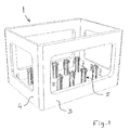
- the bottle crate 1 shown merely by way of non-limiting example in Fig. 1 comprises a base 2 and upstanding side walls, the first side walls 3 being longer than the second side walls 4.
- the side walls 3 and 4 have large openings through which the contents of the crate are visible.
- Pillars 5 are also upstanding from the base 2, extending substantially perpendicularly to the base.
- the pillars 5 serve to define bottle positions and to hold the bottles in those positions.
- the pillars 5 may assist in guiding the bottles into their positions.
- each pillar 5 of the present invention has projections (8 in Fig. 3) which press against the inserted bottles so as to hold them in place and to prevent any rattling or turning of the bottles.
- the crate is further provided with additional projections 10 which also press against the inserted bottles.
- additional projections 10 which also press against the inserted bottles.
- the projection 10 being arranged approximately halfway between two pillars 5, or at the corners of the crate, halfway between a pillar 5 and the other side wall.
- the projections 10 are shown to be arranged at an acute angle relative to the side walls, pointing towards the base 2.
- each pillar 5 consists of four elongate elements 6 which leave slots or gaps 7 between them.
- Each element 6 faces a bottle position.
- each element 6 is provided with a projection 8 which is arranged at an acute angle at the top of the respective element, pointing essentially towards the corresponding bottle position.
- the projections 8 are relatively flexible and are able to bend when a bottle is placed in the crate, thus exerting pressure on the bottles. When no bottles are present, the projections 8 protrude into the space which may be taken up by bottles.
- not only the projections 8 but also the elongate elements 6 may bend when a bottle is placed in the crate.
- This additional resilience has the advantage that the pillar 5 is able to flex more than conventional pillars, thus facilitating the insertion of bottles in the crate.
- a further advantage is that the bending, and the corresponding forces, is distributed over the projection 8 and the element 6, thus distributing the forces involved. As a result, the projection is less likely to break, thus prolonging the active service life of the crate.
- each element 6 is further provided with a reinforcing rib 9.
- the ribs 9 serve to provide additional structural strength.
- the design of the ribs allows the flexibility of the elements 6 to be controlled.
- the slots 7 serve two purposes: they allow the elements 6 to bend backwards (that is, towards the middle of the pillar), and they may accommodate the wall(s) of a bottle carrier, such as a "six-pack" or a "four-pack".
- a bottle carrier such as a "six-pack" or a "four-pack".
- each slots extends over the full height of each element 6, from its top to the base 2. This allows a maximum flexibility of the elements 6 and provides a minimum obstruction for any bottle carrier walls.
- the slots do not extend to the base 2 and may, for example, extend only from the top of the elements to approximately halfway down the elements.
- the elements 6 of the pillars 5 may be integrally formed with the (base 2 of) the crate.
- the pillars are made separately and then mounted on the base of the crate. This has the advantage that the mould for producing the crate is simplified.
- the separately produced pillars are removably mounted in the crate. This has the significant advantage of being able to replace damaged pillars.
- the pillars may be fixed to the crate by, for example, a screw thread or a snap-fit mechanism. If the pillars are separately produced but not removable, they may be attached to the crate by welding or gluing.
- the height of the pillars 5 may be chosen freely. In the embodiment of Fig. 2 the pillars reach at least to half the height of the straight part of the bottles. This embodiment allows an easy insertion and removal of the bottles.
- the pillars 5 and their projections 8 may advantageously be used to hold down the bottles, as is schematically illustrated in Fig. 4.
- the height of the element 6 is chosen such that its projection 8 extends towards the narrower section of the bottle 20, above the straight part of the bottle (the other elements of the pillar are not shown in Fig. 4 for the sake of clarity of the illustration).
- the crate 1 is preferably manufactured by injection moulding. Although the crate 1 may be produced as a single piece (that is, integrally), it may also be composed of separately produced parts. For example, the pillars 5 may be produced separately, and may be removably mounted in the crate, as mentioned above. This provides the possibility of replacing the pillars if they are damaged.
- the material of the crate is preferably a plastic material, such as HDPE (High Density PolyEthylene) or a similar material. It is, however, also possible to use other materials, such as metals (steel, aluminium, etc.).
- a plastic material such as HDPE (High Density PolyEthylene) or a similar material. It is, however, also possible to use other materials, such as metals (steel, aluminium, etc.).
- the present invention is based upon the insight that more flexible pillars allow bottles of a larger range of dimensions to be suitable clamped so as to prevent rattling.
- the present invention benefits from the further insight that flexible pillars may be achieved by providing a set of substantially resilient elements which together constitute a pillar.
- the crate of the present invention is suitable for storing and/or transporting glass bottles (such as beer bottles, water bottles and wine bottles), plastic bottles, bottles made of other materials (such as ceramic materials), and other containers.
- glass bottles such as beer bottles, water bottles and wine bottles
- plastic bottles such as plastic bottles
- bottles made of other materials such as ceramic materials
Landscapes
- Engineering & Computer Science (AREA)
- Ceramic Engineering (AREA)
- Mechanical Engineering (AREA)
- Details Of Rigid Or Semi-Rigid Containers (AREA)
Abstract
Description
- The present invention relates to a crate or similar container for storing and/or transporting bottles and similar articles. More in particular, the present invention relates to a crate comprising a base, side walls, and positioning elements defming bottle positions.
- Crates for storing and/or transporting bottles and similar articles are well known. Bottle crates typically have 12 or 24 bottle positions defmed by partitions and/or other dividing elements, for example pillars. A crate provided with such pillars, also called "cones" or "pinnacles" (German: Pinolen) is disclosed in, for example, British Patent GB 758 517 (Turner). The pillars, which extend from the base of the crate in a direction parallel to the side walls, that is vertically if the base is horizontal, each define four bottle positions and assist in the insertion of the bottles into the crate.
- It is well known that bottles may rattle during transport. As there must be sufficient spacing between the bottles and the pillars (or other dividers) to allow for variances in the dimensions of the bottles and the crate, and to allow an easy insertion and removal of the bottles, the fit of the bottles in a crate is relatively loose, allowing the bottles to move and rattle. This is in particular a problem when the labels of the bottles should be facing a certain way (for example facing a transparent area of a side wall) to be visible from outside the crate. The rattling may cause the bottles to rotate, thus turning the label away from the desired direction.
- To better hold the bottles while maintaining sufficient spacings, it has been proposed in German Patent Application DE 38 06 924 (Theysohn) to provide the pillars with spring elements which press against the bottles. These known spring elements are mounted near the base of the pillars, while the pillars are rigid. It has been found that this design allows very little variation in bottle size, bottles that are slightly larger than the standard size are difficult to insert and may even get stuck. As tolerances may vary between bottle manufacturers and suppliers, this is clearly undesirable.
- It is therefore an object of the present invention to overcome these and other problems of the Prior Art and to provide a bottle crate that allows a more effective clamping of bottles while allowing significant variations in relative bottle dimensions.
- Accordingly, the present invention provides a crate for bottles, the crate comprising a base and side walls extending from the base, wherein pillars extending from the base defme bottle positions, characterized in that the pillars are constituted by sets of elongate elements separated by slots, each element having a projection facing a bottle position for resiliently pressing against a bottle.
- By providing elongate elements that together constitute pillars, a much more flexible structure is obtained. The projections provide a certain resilience and are capable of taking up a certain variation in dimensions. The slots separating the elements allow the individual elements to bend slightly, thus providing an additional resilience not provided by the pillars of the Prior Art. The pillars of the present invention therefore present a combined resilience which offers an improved capability of accommodating bottles of varying dimensions.
- It is preferred that the projections are arranged near the top of each elongate element. This allows the greatest length of each elongate element to contribute to the resilience of the structure. Although the projections may be mounted at a relatively small distance from the top of the elements, it is further preferred that they are mounted substantially at the top, thus providing both maximum resilience and a guiding surface for the bottles when they are being inserted.
- It is further preferred that a projection extends at an acute angle relative to the associated element, substantially in the direction of insertion of the bottles. This downward angle of the projection facilitates the insertion of the bottles.
- The slots which provide the spacing between adjacent elements of the same pillar may extend over a certain distance, from the top of the pillar to approximately half the length of the pillar. In this way, a resilient structure is provided. It is preferred, however, that the slots extend from the top of the element to the base of the crate, that is, over the full height of the element. This allows the slots to be used for additional purposes, such as the insertion of walls of bottle carriers such as "six-packs".
- It is noted that US 4,071,162 (Schoeller) discloses bottle positioning pillars that consist of clusters of segments separated by gaps extending to the bottom of the crate. However, these known pillars are not resilient and the problem of rattling bottles is not addressed in said document.
- As mentioned above, the crate of the present invention may advantageously be designed for accommodating bottle carriers. That is, the inner dimensions of the crate may be chosen such that bottle carriers, such as "six-packs" and/or "four-packs", can be accommodated. In addition, the slots in the pillars may be dimensioned such that they can accommodate the walls of the bottle carriers. Typically, such bottle carriers are made of carton. The slots should be wide enough to accept two adjacent carrier walls, that is, two layers of carton. To accommodate bottle carriers, it is not necessary for the slots to extend to the base of the crate as suitable cut-outs may be made in those carriers, but such slots would be preferred as they allow a simpler carrier design.
- A pillar element may be constituted by a substantially flat, strip-like resilient part. However, such flat elements may be too flexible and may be relatively easily damaged. It is therefore preferred that each element is provided with a reinforcing rib. Such a rib, which may extend substantially perpendicularly to the flat part of the element, provides protection against damage. A proper dimensioning of the rib allows the resilience of the element to be carefully controlled. Although each element is preferably provided with one rib facing away from the respective bottle position, it is possible to provide two or more ribs per element, for example arranged in parallel.
- The pillars may be integrally formed with the crate. However, it is also possible to form the pillars separately and then mount them in the crate. In such embodiments, it is preferred that the pillars are removably mounted in the crate. This offers the advantage of being able to replace damaged pillars.
- A single pillar may comprise two elements, each element being provided with one or two projections. In case each of the two elements has two (or more) projections, each of the four bottle positions typically defmed by a pillar has at least one associated projection. However, it is preferred that a pillar is constituted by four elongate elements, each element having at least one projection. In this way, each of the four bottle positions typically defmed by a pillar has at least one associated element with at least one projection, thus maximizing the resilience provided for each bottle position.
- In an advantageous embodiment, further resilient projections are arranged at the walls. These further resilient projections may assist in positioning and clamping the bottles accommodated in the crate.
- The crate may be made from various materials, for example metal. It is preferred, however, that the crate of the present invention is manufactured from a plastics material, preferably polyethylene. The crate may be integrally produced by, for example, injection moulding.
- The present invention further provides a pillar for use in the crate defined above, and a crate wherein bottle carriers containing bottles are accommodated.
- The present invention will further be explained below with reference to exemplary embodiments illustrated in the accompanying drawings, in which:
- Fig. 1 schematically shows, in perspective, an embodiment of a crate according to the present invention.
- Fig. 2 schematically shows, in perspective, part of the embodiment of Fig. 1 in which two bottles have been inserted.
- Fig. 3 schematically shows, in perspective, part of the embodiment of Figs. 1 and 2 in more detail.
- Fig. 4 schematically shows, in side view, a bottle being held in the crate of the present invention.
- The bottle crate 1 shown merely by way of non-limiting example in Fig. 1 comprises a
base 2 and upstanding side walls, the first side walls 3 being longer than thesecond side walls 4. In the embodiment shown, theside walls 3 and 4 have large openings through which the contents of the crate are visible. -
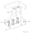
Pillars 5 are also upstanding from thebase 2, extending substantially perpendicularly to the base. Thepillars 5 serve to define bottle positions and to hold the bottles in those positions. In addition, thepillars 5 may assist in guiding the bottles into their positions. - In the partially cross-sectional view of Fig. 2 part of the crate 1 of Fig. 1 is shown in more detail. Two
bottles 20 are shown to take up bottle positions defined by thepillars 5. As will be shown in more detail in Fig. 3, eachpillar 5 of the present invention has projections (8 in Fig. 3) which press against the inserted bottles so as to hold them in place and to prevent any rattling or turning of the bottles. - In the embodiment shown in Fig. 2, the crate is further provided with
additional projections 10 which also press against the inserted bottles. Of the bottle positions bordering the side walls, there is preferably oneprojection 10 facing each position, theprojection 10 being arranged approximately halfway between twopillars 5, or at the corners of the crate, halfway between apillar 5 and the other side wall. Of course it is possible to provide two ormore projections 10 per bottle position. Theprojections 10 are shown to be arranged at an acute angle relative to the side walls, pointing towards thebase 2. - A
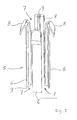
pillar 5 according to the present invention is shown in more detail in Fig. 3. In the embodiment shown, eachpillar 5 consists of fourelongate elements 6 which leave slots orgaps 7 between them. Eachelement 6 faces a bottle position. In addition, eachelement 6 is provided with aprojection 8 which is arranged at an acute angle at the top of the respective element, pointing essentially towards the corresponding bottle position. - The
projections 8 are relatively flexible and are able to bend when a bottle is placed in the crate, thus exerting pressure on the bottles. When no bottles are present, theprojections 8 protrude into the space which may be taken up by bottles. In accordance with the present invention, not only theprojections 8 but also theelongate elements 6 may bend when a bottle is placed in the crate. This additional resilience has the advantage that thepillar 5 is able to flex more than conventional pillars, thus facilitating the insertion of bottles in the crate. A further advantage is that the bending, and the corresponding forces, is distributed over theprojection 8 and theelement 6, thus distributing the forces involved. As a result, the projection is less likely to break, thus prolonging the active service life of the crate. - In the embodiment shown, each
element 6 is further provided with a reinforcingrib 9. Therib 9, which is arranged on the side of the element facing away from theprojection 8, extends over substantially the full height of each element. Theribs 9 serve to provide additional structural strength. In addition, the design of the ribs allows the flexibility of theelements 6 to be controlled. - The
slots 7 serve two purposes: they allow theelements 6 to bend backwards (that is, towards the middle of the pillar), and they may accommodate the wall(s) of a bottle carrier, such as a "six-pack" or a "four-pack". In the embodiment shown, each slots extends over the full height of eachelement 6, from its top to thebase 2. This allows a maximum flexibility of theelements 6 and provides a minimum obstruction for any bottle carrier walls. However, embodiments can be envisaged in which the slots do not extend to thebase 2 and may, for example, extend only from the top of the elements to approximately halfway down the elements. - The
elements 6 of thepillars 5 may be integrally formed with the (base 2 of) the crate. In an advantageous further embodiment, however, the pillars are made separately and then mounted on the base of the crate. This has the advantage that the mould for producing the crate is simplified. In a still further embodiment the separately produced pillars are removably mounted in the crate. This has the significant advantage of being able to replace damaged pillars. The pillars may be fixed to the crate by, for example, a screw thread or a snap-fit mechanism. If the pillars are separately produced but not removable, they may be attached to the crate by welding or gluing. - The height of the
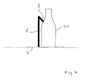
pillars 5 may be chosen freely. In the embodiment of Fig. 2 the pillars reach at least to half the height of the straight part of the bottles. This embodiment allows an easy insertion and removal of the bottles. However, thepillars 5 and theirprojections 8 may advantageously be used to hold down the bottles, as is schematically illustrated in Fig. 4. There, the height of theelement 6 is chosen such that itsprojection 8 extends towards the narrower section of thebottle 20, above the straight part of the bottle (the other elements of the pillar are not shown in Fig. 4 for the sake of clarity of the illustration). By making theelements 6 higher than the substantially straight part of the bottle, the bottle is held down and any undesired upward movement of the bottle is prevented. In this way, an additional protection against rattling is achieved. - The crate 1 is preferably manufactured by injection moulding. Although the crate 1 may be produced as a single piece (that is, integrally), it may also be composed of separately produced parts. For example, the
pillars 5 may be produced separately, and may be removably mounted in the crate, as mentioned above. This provides the possibility of replacing the pillars if they are damaged. - The material of the crate is preferably a plastic material, such as HDPE (High Density PolyEthylene) or a similar material. It is, however, also possible to use other materials, such as metals (steel, aluminium, etc.).
- The present invention is based upon the insight that more flexible pillars allow bottles of a larger range of dimensions to be suitable clamped so as to prevent rattling. The present invention benefits from the further insight that flexible pillars may be achieved by providing a set of substantially resilient elements which together constitute a pillar.
- The crate of the present invention is suitable for storing and/or transporting glass bottles (such as beer bottles, water bottles and wine bottles), plastic bottles, bottles made of other materials (such as ceramic materials), and other containers.
- It will be understood by those skilled in the art that the present invention is not limited to the embodiments illustrated above and that many modifications and additions may be made without departing from the scope of the invention as defined in the appending claims.
Claims (10)
- A crate (1) for bottles (20), the crate comprising a base (2) and side walls (3, 4) extending from the base, wherein pillars (5) extending from the base define bottle positions, characterized in that the pillars (5) are constituted by sets of elongate elements (6) separated by slots (7), each element having a projection (8) facing a bottle position for resiliently pressing against a bottle.
- The crate according to claim 1, wherein a projection (8) is arranged near the top of each elongate element (6), preferably at the top.
- The crate according to claim 1 or 2, wherein the slots (7) extend to the base (2) of the crate.
- The crate according to any of the preceding claims, which is designed for accommodating bottle carriers, each pillar (5) preferably being constituted by four elongate elements (6).
- The crate according to any of the preceding claims, wherein each element (6) is provided with a reinforcing rib (9).
- The crate according to any of the preceding claims, wherein the pillars (5) are removably mounted in the crate.
- The crate according to any of the preceding claims, wherein further resilient projections (10) are arranged at the walls (3, 4).
- The crate according to any of the preceding claims, manufactured from a plastic material, preferably polyethylene.
- The crate according to any of the preceding claims, wherein bottle carriers (10, 11) containing bottles are accommodated.
- A pillar (5) for use in the crate (1) according to any of the preceding claims.
Priority Applications (1)
| Application Number | Priority Date | Filing Date | Title |
|---|---|---|---|
| EP04077416A EP1630103A1 (en) | 2004-08-26 | 2004-08-26 | Bottle crate |
Applications Claiming Priority (1)
| Application Number | Priority Date | Filing Date | Title |
|---|---|---|---|
| EP04077416A EP1630103A1 (en) | 2004-08-26 | 2004-08-26 | Bottle crate |
Publications (1)
| Publication Number | Publication Date |
|---|---|
| EP1630103A1 true EP1630103A1 (en) | 2006-03-01 |
Family
ID=34928477
Family Applications (1)
| Application Number | Title | Priority Date | Filing Date |
|---|---|---|---|
| EP04077416A Withdrawn EP1630103A1 (en) | 2004-08-26 | 2004-08-26 | Bottle crate |
Country Status (1)
| Country | Link |
|---|---|
| EP (1) | EP1630103A1 (en) |
Cited By (3)
| Publication number | Priority date | Publication date | Assignee | Title |
|---|---|---|---|---|
| EP2236428A1 (en) | 2009-03-31 | 2010-10-06 | DW Plastics N.V. | Bottle crate with central carrier handle, central carrier handle and method of manufacturing a bottle crate with central carrier handle |
| EP2311741A1 (en) * | 2009-10-15 | 2011-04-20 | Schoeller Arca Systems GmbH | Plastic container |
| EP4434906A1 (en) * | 2023-03-24 | 2024-09-25 | Oberland M & V GmbH | Bottle crate and container carrier |
Citations (5)
| Publication number | Priority date | Publication date | Assignee | Title |
|---|---|---|---|---|
| DE2848373A1 (en) * | 1978-11-08 | 1980-05-22 | Spumalit Anstalt | Plastics bottle crate construction - has spacers shaped to allow carrying individual bottles and sets of bottles held in bottle carriers |
| US4538742A (en) * | 1982-05-13 | 1985-09-03 | Prodel Ulrich H | Plastic bottle case and bottle packaging with such case |
| DE3801224A1 (en) * | 1987-09-28 | 1989-04-13 | Schoeller & Co Ag A | Bottle crate |
| EP0714833A1 (en) * | 1994-12-01 | 1996-06-05 | The Coca-Cola Company | Container for bottles or cans |
| US5964343A (en) * | 1995-11-28 | 1999-10-12 | Steiner Technology Gmbh | Carrying plate for beverage cans |
-
2004
- 2004-08-26 EP EP04077416A patent/EP1630103A1/en not_active Withdrawn
Patent Citations (5)
| Publication number | Priority date | Publication date | Assignee | Title |
|---|---|---|---|---|
| DE2848373A1 (en) * | 1978-11-08 | 1980-05-22 | Spumalit Anstalt | Plastics bottle crate construction - has spacers shaped to allow carrying individual bottles and sets of bottles held in bottle carriers |
| US4538742A (en) * | 1982-05-13 | 1985-09-03 | Prodel Ulrich H | Plastic bottle case and bottle packaging with such case |
| DE3801224A1 (en) * | 1987-09-28 | 1989-04-13 | Schoeller & Co Ag A | Bottle crate |
| EP0714833A1 (en) * | 1994-12-01 | 1996-06-05 | The Coca-Cola Company | Container for bottles or cans |
| US5964343A (en) * | 1995-11-28 | 1999-10-12 | Steiner Technology Gmbh | Carrying plate for beverage cans |
Cited By (4)
| Publication number | Priority date | Publication date | Assignee | Title |
|---|---|---|---|---|
| EP2236428A1 (en) | 2009-03-31 | 2010-10-06 | DW Plastics N.V. | Bottle crate with central carrier handle, central carrier handle and method of manufacturing a bottle crate with central carrier handle |
| EP2676891A2 (en) | 2009-03-31 | 2013-12-25 | D W Plastics N.V. | Bottle crate with central carrier handle, central carrier handle and method of manufacturing a bottle crate with central carrier handle. |
| EP2311741A1 (en) * | 2009-10-15 | 2011-04-20 | Schoeller Arca Systems GmbH | Plastic container |
| EP4434906A1 (en) * | 2023-03-24 | 2024-09-25 | Oberland M & V GmbH | Bottle crate and container carrier |
Similar Documents
| Publication | Publication Date | Title |
|---|---|---|
| US5823376A (en) | Nestable crate for beverage bottles | |
| EP3412594B1 (en) | Container carrier | |
| US6047844A (en) | Nestable crate for beverage bottles | |
| EP2239202B1 (en) | Low depth stackable tray | |
| US20100132311A1 (en) | Crate for containers | |
| EP2090516A1 (en) | Crate for Containers | |
| CA2513041C (en) | Stacking crate | |
| HU219151B (en) | Tray for filling bottles | |
| US20050230281A1 (en) | Nestable crate for containers | |
| AU2017204287B2 (en) | Nesting Container Carrier | |
| EP1630103A1 (en) | Bottle crate | |
| KR200476256Y1 (en) | Vessel for transporting plate-shaped articles | |
| EP0322152B1 (en) | A crate | |
| JP3220792U (en) | Heat insulation container | |
| EP4298023B1 (en) | Multipurpose bottle crate | |
| US3531014A (en) | Carrying case for bottles | |
| US20250153313A1 (en) | Workpiece carrier frame and workpiece carrier frame system | |
| JP4736638B2 (en) | Cup holder device | |
| JP5165512B2 (en) | Fruit packaging container | |
| EP1520791B1 (en) | Crate for bottle carriers | |
| JP2010064761A (en) | Fruit packaging container | |
| JP7634879B2 (en) | Tray/lid and storage unit | |
| JP3655458B2 (en) | Bobbin holding plate | |
| SK111596A3 (en) | Container system for documents | |
| CA1312311C (en) | Bottle tray |
Legal Events
| Date | Code | Title | Description |
|---|---|---|---|
| PUAI | Public reference made under article 153(3) epc to a published international application that has entered the european phase |
Free format text: ORIGINAL CODE: 0009012 |
|
| AK | Designated contracting states |
Kind code of ref document: A1 Designated state(s): AT BE BG CH CY CZ DE DK EE ES FI FR GB GR HU IE IT LI LU MC NL PL PT RO SE SI SK TR |
|
| AX | Request for extension of the european patent |
Extension state: AL HR LT LV MK |
|
| 17P | Request for examination filed |
Effective date: 20060901 |
|
| AKX | Designation fees paid |
Designated state(s): AT BE BG CH CY CZ DE DK EE ES FI FR GB GR HU IE IT LI LU MC NL PL PT RO SE SI SK TR |
|
| 17Q | First examination report despatched |
Effective date: 20070125 |
|
| STAA | Information on the status of an ep patent application or granted ep patent |
Free format text: STATUS: THE APPLICATION IS DEEMED TO BE WITHDRAWN |
|
| 18D | Application deemed to be withdrawn |
Effective date: 20070807 |