EP1630045A1 - Occupant protection system including an airbag and a curtain sheet - Google Patents
Occupant protection system including an airbag and a curtain sheet Download PDFInfo
- Publication number
- EP1630045A1 EP1630045A1 EP05014879A EP05014879A EP1630045A1 EP 1630045 A1 EP1630045 A1 EP 1630045A1 EP 05014879 A EP05014879 A EP 05014879A EP 05014879 A EP05014879 A EP 05014879A EP 1630045 A1 EP1630045 A1 EP 1630045A1
- Authority
- EP
- European Patent Office
- Prior art keywords
- curtain sheet
- air bag
- occupant
- protection system
- rope
- Prior art date
- Legal status (The legal status is an assumption and is not a legal conclusion. Google has not performed a legal analysis and makes no representation as to the accuracy of the status listed.)
- Withdrawn
Links
- 230000004913 activation Effects 0.000 description 2
- 239000005357 flat glass Substances 0.000 description 1
- 238000003780 insertion Methods 0.000 description 1
- 230000037431 insertion Effects 0.000 description 1
- 238000000034 method Methods 0.000 description 1
- 239000011347 resin Substances 0.000 description 1
- 229920005989 resin Polymers 0.000 description 1
- 230000000717 retained effect Effects 0.000 description 1
- 238000005096 rolling process Methods 0.000 description 1
Images


Classifications
-
- B—PERFORMING OPERATIONS; TRANSPORTING
- B60—VEHICLES IN GENERAL
- B60R—VEHICLES, VEHICLE FITTINGS, OR VEHICLE PARTS, NOT OTHERWISE PROVIDED FOR
- B60R21/00—Arrangements or fittings on vehicles for protecting or preventing injuries to occupants or pedestrians in case of accidents or other traffic risks
- B60R21/02—Occupant safety arrangements or fittings, e.g. crash pads
- B60R21/16—Inflatable occupant restraints or confinements designed to inflate upon impact or impending impact, e.g. air bags
- B60R21/23—Inflatable members
- B60R21/231—Inflatable members characterised by their shape, construction or spatial configuration
- B60R21/2334—Expansion control features
- B60R21/2338—Tethers
-
- B—PERFORMING OPERATIONS; TRANSPORTING
- B60—VEHICLES IN GENERAL
- B60R—VEHICLES, VEHICLE FITTINGS, OR VEHICLE PARTS, NOT OTHERWISE PROVIDED FOR
- B60R21/00—Arrangements or fittings on vehicles for protecting or preventing injuries to occupants or pedestrians in case of accidents or other traffic risks
- B60R21/02—Occupant safety arrangements or fittings, e.g. crash pads
- B60R21/06—Safety nets, transparent sheets, curtains, or the like, e.g. between occupants and glass
- B60R21/08—Safety nets, transparent sheets, curtains, or the like, e.g. between occupants and glass automatically movable from an inoperative to an operative position, e.g. in a collision
-
- B—PERFORMING OPERATIONS; TRANSPORTING
- B60—VEHICLES IN GENERAL
- B60R—VEHICLES, VEHICLE FITTINGS, OR VEHICLE PARTS, NOT OTHERWISE PROVIDED FOR
- B60R21/00—Arrangements or fittings on vehicles for protecting or preventing injuries to occupants or pedestrians in case of accidents or other traffic risks
- B60R2021/0002—Type of accident
- B60R2021/0006—Lateral collision
-
- B—PERFORMING OPERATIONS; TRANSPORTING
- B60—VEHICLES IN GENERAL
- B60R—VEHICLES, VEHICLE FITTINGS, OR VEHICLE PARTS, NOT OTHERWISE PROVIDED FOR
- B60R21/00—Arrangements or fittings on vehicles for protecting or preventing injuries to occupants or pedestrians in case of accidents or other traffic risks
- B60R2021/0002—Type of accident
- B60R2021/0018—Roll-over
-
- B—PERFORMING OPERATIONS; TRANSPORTING
- B60—VEHICLES IN GENERAL
- B60R—VEHICLES, VEHICLE FITTINGS, OR VEHICLE PARTS, NOT OTHERWISE PROVIDED FOR
- B60R21/00—Arrangements or fittings on vehicles for protecting or preventing injuries to occupants or pedestrians in case of accidents or other traffic risks
- B60R21/02—Occupant safety arrangements or fittings, e.g. crash pads
- B60R21/16—Inflatable occupant restraints or confinements designed to inflate upon impact or impending impact, e.g. air bags
- B60R21/23—Inflatable members
- B60R21/231—Inflatable members characterised by their shape, construction or spatial configuration
- B60R21/2334—Expansion control features
- B60R21/2338—Tethers
- B60R2021/23386—External tether means
-
- B—PERFORMING OPERATIONS; TRANSPORTING
- B60—VEHICLES IN GENERAL
- B60R—VEHICLES, VEHICLE FITTINGS, OR VEHICLE PARTS, NOT OTHERWISE PROVIDED FOR
- B60R21/00—Arrangements or fittings on vehicles for protecting or preventing injuries to occupants or pedestrians in case of accidents or other traffic risks
- B60R21/02—Occupant safety arrangements or fittings, e.g. crash pads
- B60R21/16—Inflatable occupant restraints or confinements designed to inflate upon impact or impending impact, e.g. air bags
- B60R21/23—Inflatable members
- B60R21/231—Inflatable members characterised by their shape, construction or spatial configuration
- B60R21/23138—Inflatable members characterised by their shape, construction or spatial configuration specially adapted for side protection
-
- B—PERFORMING OPERATIONS; TRANSPORTING
- B60—VEHICLES IN GENERAL
- B60R—VEHICLES, VEHICLE FITTINGS, OR VEHICLE PARTS, NOT OTHERWISE PROVIDED FOR
- B60R21/00—Arrangements or fittings on vehicles for protecting or preventing injuries to occupants or pedestrians in case of accidents or other traffic risks
- B60R21/02—Occupant safety arrangements or fittings, e.g. crash pads
- B60R21/16—Inflatable occupant restraints or confinements designed to inflate upon impact or impending impact, e.g. air bags
- B60R21/23—Inflatable members
- B60R21/231—Inflatable members characterised by their shape, construction or spatial configuration
- B60R21/232—Curtain-type airbags deploying mainly in a vertical direction from their top edge
Definitions
- the present invention relates to an occupant protection system that protects an occupant of a vehicle when the vehicle is involved in a side collision or turns on its side.
- side air bag devices and curtain air bag devices are known as occupant protection systems that protect an occupant by preventing the occupant from hitting a side door when a vehicle is involved in a side collision or turns on its side (for example, see JP-A-10-175499 (Patent Document 1) and JP-A-2000-62562 (Patent Document 2)).
- the turning on the side includes rollovers.
- An object of the present invention is to provide an occupant protection system that can effectively protect an occupant with a side air bag device and a curtain sheet, for example, in the event of a side collision or turning on the side and that can be stored in a reduced space of a vehicle.
- An occupant protection system of the present invention includes a side air bag that is inflated beside an occupant of a vehicle, and a curtain sheet that is normally out of a position such as to cover a window beside a seat and that is stretched to cover the window from a cabin side of the vehicle in an emergency.
- the side air bag is inflated beside at least a part between the hip and head of the occupant.
- the curtain sheet is secured at an upper side to a chassis above the window, and is stretched to cover the window by being pulled at a lower side by a pulling means.
- a linear member is mounted along the lower side of the curtain sheet, and is fixed at one end to the chassis, and the pulling means pulls the other end of the linear member.
- the pulling means has a stopper means for preventing a retractive movement after pulling.
- the curtain sheet is placed between the side air bag and the window in a state in which the side air bag is completely inflated and the curtain sheet is completely stretched.
- the curtain sheet When a vehicle having the occupant protection system of the present invention is involved in a side collision or turns on its side, the curtain sheet is stretched along the window beside the seat, and the side air bag is inflated on a cabin side of the curtain sheet.
- the inflated side air bag receives the occupant, and absorbs an impact. Even when the window is open or broken, the curtain sheet prevents the side air bag from moving out of the window, and therefore, the impact can be absorbed sufficiently.
- the stretched curtain sheet also serves to retain the occupant inside the cabin of the vehicle.
- the occupant protection system of the present invention does not adopt a curtain air bag device, but adopts the curtain sheet. This can make the storage space in the vehicle smaller than when the curtain air bag device is adopted.
- the side air bag be inflated beside at least a part between the hip and head of the occupant.
- Such a side air bag receives almost the entire side portion of the body of the occupant sitting on the seat, and sufficiently protects the occupant.
- the curtain sheet may be secured at the upper side to the chassis above the window, and may be stretched to cover the window by being pulled at the lower side by a pulling means.
- a pulling means When the curtain sheet is thus pulled by the pulling means, it can be quickly stretched even when slipping on, for example, a pillar of the chassis.
- a linear member be provided along the lower side of the curtain sheet, and be fixed at one end to the chassis, and the pulling means pulls the other end of the linear member.
- the linear member can stretch the curtain sheet so that the lower side has a sufficient tensile force (so that the lower side is tightly stretched).
- the pulling means has a stopper means for preventing a retractive movement after pulling, the stretched curtain sheet is held under high tension, and can extremely reliably receive the side air bag and the occupant for a long period.
- a seat 10 in the car includes a seat cushion 11, a seat back 12, and a headrest 13.
- a shoulder anchor is provided on a B-pillar 16, and a shoulder belt is hung on the shoulder anchor.
- the shoulder belt is attached to a buckle 14 via a tongue.
- a side air bag device 20 including a side bag 21 that is inflated along a front door 22 and an inflator (not shown) for inflation is provided at the front door 22 or the seat 10 (the seat 10 in this embodiment).
- a curtain sheet device 30 extends from an A-pillar 15 of the car to a C-pillar 17 through a roof side rail 18. In cases of a side collision and rolling, a curtain sheet 31 can be stretched between the A-pillar 15 and the C-pillar 17 to cover windows 22a and 23a of the front door 22 and a rear door 23.
- the curtain sheet 31 is folded up in an elongated form, and is disposed along the roof side rail 18 while the form is retained by, for example, a breakable tape.
- the curtain sheet 31 is covered with a roof head lining (not shown).
- a plurality of lugs 31a project from an upper side of the curtain sheet 31.
- the lugs 31a are fastened to the A-pillar 15 and the roof side rail 18 by, for example, bolts or rivets.
- a lower side of the curtain sheet 31 is turned up and sewn to form a tunnel-shaped rope extending portion 31b.
- a rope 32 extends through the rope extending portion 31b.
- a front end of the rope 32 is connected to the bottom of the A-pillar 15 via a rope anchor 33, and a rear end thereof is connected to the top of the C-pillar 17 via a rope anchor 34.
- the curtain sheet device 30 includes a guide rail 35 that is mounted on the C-pillar 17 to function as a pulling means for pulling the curtain sheet 31 downward and that extends vertically, a slider 36 that is slidable along the guide rail 35, an actuator 37 for moving the slider 36 by the action of the blow pressure of gas, and a one-way clutch 38 provided at the bottom of the guide rail 35.
- the actuator 37 includes a gas generator, and a multistage piston (not shown) that extends along the guide rail 35 by the blow pressure of gas from the gas generator.
- the gas generator starts, the piston expands to push the slider 36, and the slider 36 moves along the guide rail 35.
- the slider 36 reaches a lower end of the guide rail 35, it is latched by the one-way clutch 38, and is thereby prevented from retracting upward.
- the rear end of the rope 32 drawn out of a rear end of the rope extending portion 31b is hung on the slider 36, and is then connected to the rope anchor 34.
- the actuator 37 and the inflator of the side air bag device 20 are activated.
- the slider 36 moves along the guide rail 35, and pushes down the rear portion of the rope 32, thereby stretching the curtain sheet 31, as shown in Fig. 1(b).
- the curtain sheet 31 pushes a side edge of the roof head lining open, and stretches downward along the cabin sides of the windows 22a and 23a.
- the rope 31 is tightly stretched between the slider 36 and the rope anchor 33, and the curtain sheet 31 covers the windows 22a and 23a of the doors 22 and 23.
- the side air bag 21 is inflated beside a part between the hip and head of an occupant on the seat 10. While the side air bag 21 is inflated, it is placed on the cabin side of the stretched curtain sheet 31. Since the inflated side air bag 21 receives the occupant from the side, the impact applied to the occupant is absorbed.
- the stretched curtain sheet 31 covers the windows 22a and 23a, even when the window glasses of the doors 22 and 23 are open or broken, the occupant remains inside the car.
- the stretched curtain sheet 31 also backs up the inflated side air bag 21, and prevents the side air bag 31 from moving toward the outside of the car.
- a piston-shaped slider may be directly moved by the blow pressure of gas from the gas generator.
- Fig. 2 shows an example of such a method.
- a cylinder-shaped guide rail 40 extends in the front-rear direction of the vehicle body at the bottom of a C-pillar 17.
- a piston-shaped slider 41 is placed inside a guide rail 40.
- a rear end of a rope 32 is connected to the slider 41. At least the rear end of the rope 32 is resistant to heat. The rear end of the rope 32 is guided into the guide rail 40 by a sheave 42.
- a front end of the guide rail 40 is closed by a head end plate.
- the head end plate has an insertion hole (not shown) through which the rope 32 is inserted.
- a gas generator 43 is connected to the guide rail 40 to supply gas between the head end plate and the slider 41.
- a one-way clutch 44 is provided at a rear end of the guide rail 40.
- a side air bag 20 operates in a manner similar to that in the above embodiment. In this embodiment, operative advantages similar to those in the above embodiment are provided.
- guide rail 40 extends laterally in Fig. 2, it may extend vertically so that its end at the one-way clutch 44 is placed on the upper side.
- Fig. 3 shows an embodiment in which expandable chambers 50 and 51 are provided in a curtain sheet 31A, are inflated by the supply of gas from a gas generator 53, and a rope 32 is pulled by the force of inflation.
- the chamber 50 extends in the front-rear direction of the vehicle body along an upper side of the curtain sheet 31A.
- the gas generator 53 is connected to a rear end of the chamber 50 via a duct 54.
- the chamber 51 branches off from the chamber 50 at a longitudinal midpoint, extends down through almost the center of a window 23a, and reaches a lower side of the curtain sheet 31A.
- Sheaves 56, 57, and 58 are provided at the bottom of the C-pillar 17 and in the rear of a roof side rail 18.
- a rope 32 extending from a rear end of a rope extending portion 31b is hung on the sheave 56, is hung on the sheaves 57 and 58 provided above the window 23a, and is guided into the chamber 51.
- the rope 32 extends inside the chamber 51, and is connected at the tail end to the curtain sheet 31A near the lower end of the chamber 51.
- a one-way rope clutch 59 is provided between the sheaves 56 and 57 to allow the rope 32 only to move from the sheave 56 to the sheave 57.
- This embodiment provides operational advantages similar to those in the above embodiments.
- This embodiment is also advantageous in that the chamber 51 receives the head of an occupant on a rear seat and absorbs an impact.
- the above embodiments are exemplary embodiments of the present invention, and the present invention also includes embodiments other than the illustrated embodiments.
- a wire, a belt, a soft resin rod, or a tube may be used as a linear member, instead of the rope.
- the pulling means is not limited to the means using the gas generator as a power source, and, for example, a motor and a linear solenoid may be used as the power source.
Landscapes
- Engineering & Computer Science (AREA)
- Mechanical Engineering (AREA)
- Air Bags (AREA)
Abstract

Description
- The present invention relates to an occupant protection system that protects an occupant of a vehicle when the vehicle is involved in a side collision or turns on its side.
- For example, side air bag devices and curtain air bag devices are known as occupant protection systems that protect an occupant by preventing the occupant from hitting a side door when a vehicle is involved in a side collision or turns on its side (for example, see JP-A-10-175499 (Patent Document 1) and JP-A-2000-62562 (Patent Document 2)). In this specification, the turning on the side includes rollovers.
- An object of the present invention is to provide an occupant protection system that can effectively protect an occupant with a side air bag device and a curtain sheet, for example, in the event of a side collision or turning on the side and that can be stored in a reduced space of a vehicle.
- An occupant protection system of the present invention includes a side air bag that is inflated beside an occupant of a vehicle, and a curtain sheet that is normally out of a position such as to cover a window beside a seat and that is stretched to cover the window from a cabin side of the vehicle in an emergency.
- In the occupant protection system claimed in claim 2 according to claim 1, the side air bag is inflated beside at least a part between the hip and head of the occupant.
- In the occupant protection system claimed in claim 3 according to claim 1 or 2, the curtain sheet is secured at an upper side to a chassis above the window, and is stretched to cover the window by being pulled at a lower side by a pulling means.
- In the occupant protection system claimed in claim 4 according to claim 3, a linear member is mounted along the lower side of the curtain sheet, and is fixed at one end to the chassis, and the pulling means pulls the other end of the linear member.
- In the occupant protection system claimed in claim 5 according to claim 3 or 4, the pulling means has a stopper means for preventing a retractive movement after pulling.
- In the occupant protection system claimed in claim 6 according to any one of claims 1 to 5, the curtain sheet is placed between the side air bag and the window in a state in which the side air bag is completely inflated and the curtain sheet is completely stretched.
- When a vehicle having the occupant protection system of the present invention is involved in a side collision or turns on its side, the curtain sheet is stretched along the window beside the seat, and the side air bag is inflated on a cabin side of the curtain sheet. The inflated side air bag receives the occupant, and absorbs an impact. Even when the window is open or broken, the curtain sheet prevents the side air bag from moving out of the window, and therefore, the impact can be absorbed sufficiently. The stretched curtain sheet also serves to retain the occupant inside the cabin of the vehicle.
- The occupant protection system of the present invention does not adopt a curtain air bag device, but adopts the curtain sheet. This can make the storage space in the vehicle smaller than when the curtain air bag device is adopted.
- In the occupant protection system of the present invention, it is preferable that the side air bag be inflated beside at least a part between the hip and head of the occupant. Such a side air bag receives almost the entire side portion of the body of the occupant sitting on the seat, and sufficiently protects the occupant.
- In the present invention, the curtain sheet may be secured at the upper side to the chassis above the window, and may be stretched to cover the window by being pulled at the lower side by a pulling means. When the curtain sheet is thus pulled by the pulling means, it can be quickly stretched even when slipping on, for example, a pillar of the chassis.
- In this case, it is preferable that a linear member be provided along the lower side of the curtain sheet, and be fixed at one end to the chassis, and the pulling means pulls the other end of the linear member. The linear member can stretch the curtain sheet so that the lower side has a sufficient tensile force (so that the lower side is tightly stretched).
- When the pulling means has a stopper means for preventing a retractive movement after pulling, the stretched curtain sheet is held under high tension, and can extremely reliably receive the side air bag and the occupant for a long period.
- Embodiments will be described below with reference to the drawings.
- Figs. 1(a) and 1(b) are perspective views showing an embodiment;
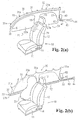
- Figs. 2(a) and 2(b) are perspective views showing another embodiment; and
- Figs. 3(a) and 3(b) are perspective views showing a further embodiment.
- In Fig. 1, a
seat 10 in the car includes aseat cushion 11, a seat back 12, and aheadrest 13. Although not shown, a shoulder anchor is provided on a B-pillar 16, and a shoulder belt is hung on the shoulder anchor. The shoulder belt is attached to abuckle 14 via a tongue. - A side
air bag device 20 including aside bag 21 that is inflated along afront door 22 and an inflator (not shown) for inflation is provided at thefront door 22 or the seat 10 (theseat 10 in this embodiment). - A
curtain sheet device 30 extends from anA-pillar 15 of the car to a C-pillar 17 through aroof side rail 18. In cases of a side collision and rolling, acurtain sheet 31 can be stretched between theA-pillar 15 and the C-pillar 17 to coverwindows front door 22 and arear door 23. - The
curtain sheet 31 is folded up in an elongated form, and is disposed along theroof side rail 18 while the form is retained by, for example, a breakable tape. Thecurtain sheet 31 is covered with a roof head lining (not shown). - A plurality of
lugs 31a project from an upper side of thecurtain sheet 31. Thelugs 31a are fastened to theA-pillar 15 and theroof side rail 18 by, for example, bolts or rivets. - A lower side of the
curtain sheet 31 is turned up and sewn to form a tunnel-shapedrope extending portion 31b. Arope 32 extends through therope extending portion 31b. A front end of therope 32 is connected to the bottom of the A-pillar 15 via arope anchor 33, and a rear end thereof is connected to the top of the C-pillar 17 via arope anchor 34. In this embodiment, thecurtain sheet device 30 includes aguide rail 35 that is mounted on the C-pillar 17 to function as a pulling means for pulling thecurtain sheet 31 downward and that extends vertically, aslider 36 that is slidable along theguide rail 35, anactuator 37 for moving theslider 36 by the action of the blow pressure of gas, and a one-way clutch 38 provided at the bottom of theguide rail 35. Theactuator 37 includes a gas generator, and a multistage piston (not shown) that extends along theguide rail 35 by the blow pressure of gas from the gas generator. When the gas generator starts, the piston expands to push theslider 36, and theslider 36 moves along theguide rail 35. When theslider 36 reaches a lower end of theguide rail 35, it is latched by the one-way clutch 38, and is thereby prevented from retracting upward. - The rear end of the
rope 32 drawn out of a rear end of therope extending portion 31b is hung on theslider 36, and is then connected to therope anchor 34. - When the car provided with the side
air bag device 20 and thecurtain sheet device 30 thus constructed is involved in a side collision or turns on its side, theactuator 37 and the inflator of the sideair bag device 20 are activated. By the activation of theactuator 37, theslider 36 moves along theguide rail 35, and pushes down the rear portion of therope 32, thereby stretching thecurtain sheet 31, as shown in Fig. 1(b). Thecurtain sheet 31 pushes a side edge of the roof head lining open, and stretches downward along the cabin sides of thewindows slider 36 is latched by the one-way clutch 28, therope 31 is tightly stretched between theslider 36 and therope anchor 33, and thecurtain sheet 31 covers thewindows doors - By the activation of the inflator of the side
air bag device 20, theside air bag 21 is inflated beside a part between the hip and head of an occupant on theseat 10. While theside air bag 21 is inflated, it is placed on the cabin side of the stretchedcurtain sheet 31. Since the inflatedside air bag 21 receives the occupant from the side, the impact applied to the occupant is absorbed. - Since the
stretched curtain sheet 31 covers thewindows doors curtain sheet 31 also backs up the inflatedside air bag 21, and prevents theside air bag 31 from moving toward the outside of the car. - While the
multistage actuator 37 using the gas generator as a driving power source is adopted in the above embodiment, a piston-shaped slider may be directly moved by the blow pressure of gas from the gas generator. Fig. 2 shows an example of such a method. A cylinder-shaped guide rail 40 extends in the front-rear direction of the vehicle body at the bottom of a C-pillar 17. A piston-shaped slider 41 is placed inside aguide rail 40. A rear end of arope 32 is connected to theslider 41. At least the rear end of therope 32 is resistant to heat. The rear end of therope 32 is guided into theguide rail 40 by asheave 42. - A front end of the
guide rail 40 is closed by a head end plate. The head end plate has an insertion hole (not shown) through which therope 32 is inserted. Agas generator 43 is connected to theguide rail 40 to supply gas between the head end plate and theslider 41. A one-way clutch 44 is provided at a rear end of theguide rail 40. - When the
gas generator 43 is activated, theslider 41 moves rearward along theguide rail 40 until it is latched by the one-way clutch 44, as shown in Fig. 2(b). Consequently, therope 32 is tightly stretched, and thecurtain sheet 31 is stretched to coverwindows side air bag 20 operates in a manner similar to that in the above embodiment. In this embodiment, operative advantages similar to those in the above embodiment are provided. - While the
guide rail 40 extends laterally in Fig. 2, it may extend vertically so that its end at the one-way clutch 44 is placed on the upper side. - Fig. 3 shows an embodiment in which
expandable chambers 50 and 51 are provided in acurtain sheet 31A, are inflated by the supply of gas from agas generator 53, and arope 32 is pulled by the force of inflation. - As shown in Fig. 3(b), the
chamber 50 extends in the front-rear direction of the vehicle body along an upper side of thecurtain sheet 31A. Thegas generator 53 is connected to a rear end of thechamber 50 via aduct 54. The chamber 51 branches off from thechamber 50 at a longitudinal midpoint, extends down through almost the center of awindow 23a, and reaches a lower side of thecurtain sheet 31A. - Sheaves 56, 57, and 58 are provided at the bottom of the C-
pillar 17 and in the rear of aroof side rail 18. Arope 32 extending from a rear end of arope extending portion 31b is hung on thesheave 56, is hung on thesheaves window 23a, and is guided into the chamber 51. Therope 32 extends inside the chamber 51, and is connected at the tail end to thecurtain sheet 31A near the lower end of the chamber 51. A one-way rope clutch 59 is provided between thesheaves rope 32 only to move from thesheave 56 to thesheave 57. - When the
gas generator 53 is activated, gas blown from thegas generator 53 flows straight, and first inflates thechamber 50. A roof lining covering thecurtain sheet 31A is thereby pushed open, and a space is formed between the roof lining and a side portion of the vehicle body. The gas flows from thechamber 50 into the chamber 51, and thechamber 50 expands downward through the space. A portion of thecurtain sheet 31A adjoining the chamber 51 also stretches downward through the space while being dragged by the chamber 51. With the downward expansion of the chamber 51, the tail end of therope 32 is pulled downward, and theentire curtain sheet 31A is stretched downward through the space. Finally, a stretch finished state shown in Fig. 3(b) is brought about, and thecurtain sheet 31A covers thewindows rope 32 is latched by therope clutch 59, and is held under high tension. - Other structures in Fig. 3 are similar to those in the above embodiments, and the same reference numerals denote the same components.
- This embodiment provides operational advantages similar to those in the above embodiments. This embodiment is also advantageous in that the chamber 51 receives the head of an occupant on a rear seat and absorbs an impact.
- The above embodiments are exemplary embodiments of the present invention, and the present invention also includes embodiments other than the illustrated embodiments. For example, a wire, a belt, a soft resin rod, or a tube may be used as a linear member, instead of the rope. The pulling means is not limited to the means using the gas generator as a power source, and, for example, a motor and a linear solenoid may be used as the power source.
Figs. 1(a) and 1(b) are perspective views of a front seat in a car provided with an occupant protection system according to an embodiment, respectively, showing a state before a side air bag is inflated and a curtain sheet is stretched, and a state after the side air bag is inflated and the curtain sheet is stretched.
Claims (6)
- An occupant protection system comprising:a side air bag that is inflated beside an occupant of a vehicle; anda curtain sheet that is normally out of a position such as to cover a window disposed beside a seat and that is stretched to cover the window from a cabin side of the vehicle in an emergency.
- The occupant protection system according to claim 1, wherein the side air bag is inflated beside at least a part between the hip and head of the occupant.
- The occupant protection system according to claim 1 or 2, wherein the curtain sheet is secured at an upper side to a chassis above the window, and is stretched to cover the window by being pulled at a lower side by pulling means.
- The occupant protection system according to claim 3, wherein a linear member is mounted along the lower side of the curtain sheet, and is fixed at one end to the chassis, and the pulling means pulls the other end of the linear member.
- The occupant protection system according to claim 3 or 4, wherein the pulling means has stopper means for preventing a retractive movement after pulling.
- The occupant protection system according to any one of claims 1 to 5, wherein the curtain sheet is placed between the side air bag and the window in a state in which the side air bag is completely inflated and the curtain sheet is completely stretched.
Applications Claiming Priority (1)
| Application Number | Priority Date | Filing Date | Title |
|---|---|---|---|
| JP2004252630A JP2006069280A (en) | 2004-08-31 | 2004-08-31 | Occupant crash protection device |
Publications (1)
| Publication Number | Publication Date |
|---|---|
| EP1630045A1 true EP1630045A1 (en) | 2006-03-01 |
Family
ID=35241002
Family Applications (1)
| Application Number | Title | Priority Date | Filing Date |
|---|---|---|---|
| EP05014879A Withdrawn EP1630045A1 (en) | 2004-08-31 | 2005-07-08 | Occupant protection system including an airbag and a curtain sheet |
Country Status (4)
| Country | Link |
|---|---|
| US (1) | US20060043706A1 (en) |
| EP (1) | EP1630045A1 (en) |
| JP (1) | JP2006069280A (en) |
| CN (1) | CN1743209A (en) |
Families Citing this family (14)
| Publication number | Priority date | Publication date | Assignee | Title |
|---|---|---|---|---|
| JP4851155B2 (en) * | 2005-10-20 | 2012-01-11 | オートリブ ディベロップメント エービー | Occupant protection system |
| WO2008011414A2 (en) * | 2006-07-17 | 2008-01-24 | Delphi Technologies, Inc. | Side curtain airbag with extended shoulder portion |
| JP4420067B2 (en) | 2007-05-23 | 2010-02-24 | トヨタ自動車株式会社 | Airbag device for vehicle |
| US8353529B2 (en) * | 2007-09-16 | 2013-01-15 | Toyota Motor East Japan, Inc. | Airbag apparatus |
| US8814202B2 (en) * | 2010-08-06 | 2014-08-26 | Autoliv Development Ab | Curtain airbag |
| JP5263367B2 (en) * | 2011-10-17 | 2013-08-14 | 日産自動車株式会社 | Vehicle occupant protection device |
| US9156427B2 (en) * | 2014-01-08 | 2015-10-13 | Autoliv Asp, Inc. | Cost-effective use of one-piece woven fabric for curtain airbags |
| US9333931B1 (en) | 2015-01-28 | 2016-05-10 | Ford Global Technologies, Llc | Passenger protection system |
| US9511734B2 (en) | 2015-01-29 | 2016-12-06 | Ford Global Technologies, Llc | Passenger protection system |
| JP6304166B2 (en) * | 2015-08-03 | 2018-04-04 | トヨタ自動車株式会社 | Crew protection device |
| CN112440926A (en) * | 2019-08-14 | 2021-03-05 | 郑州宇通客车股份有限公司 | Side air curtain protection system and vehicle |
| US11214227B2 (en) * | 2020-01-10 | 2022-01-04 | ZF Passive Safety Systems US Inc. | Airbag with deployment or movement controlling tensioner |
| JP7380499B2 (en) * | 2020-09-29 | 2023-11-15 | トヨタ自動車株式会社 | Vehicle occupant protection device |
| US11702029B1 (en) * | 2021-03-26 | 2023-07-18 | Apple Inc. | Deployable restraints with tensioning mechanisms |
Citations (7)
| Publication number | Priority date | Publication date | Assignee | Title |
|---|---|---|---|---|
| JPH10175499A (en) | 1996-12-20 | 1998-06-30 | Kansei Corp | Side air bag |
| JP2000062562A (en) | 1998-08-25 | 2000-02-29 | Toyota Motor Corp | Head protection airbag device |
| WO2001021449A1 (en) * | 1999-09-21 | 2001-03-29 | Simula, Inc. | Dynamically deployed device shield |
| EP1279571A1 (en) * | 2000-05-01 | 2003-01-29 | Toyoda Gosei Co., Ltd. | Occupant arresting device |
| EP1279570A1 (en) * | 2000-05-01 | 2003-01-29 | Toyoda Gosei Co., Ltd. | Occupant arresting device |
| US20030075906A1 (en) * | 2000-05-01 | 2003-04-24 | Michio Inoue | Occupant arresting device |
| US20030132619A1 (en) * | 2002-01-15 | 2003-07-17 | Winarto Joko P. | Containment impact protection system |
Family Cites Families (11)
| Publication number | Priority date | Publication date | Assignee | Title |
|---|---|---|---|---|
| DE4137749A1 (en) * | 1991-11-15 | 1993-05-19 | Kolbenschmidt Ag | SAFETY DEVICE |
| DE19538657A1 (en) * | 1995-10-17 | 1997-04-24 | Trw Repa Gmbh | Airbag side impact protection device |
| US5718450A (en) * | 1996-01-19 | 1998-02-17 | Takata, Inc. | Inflatable restraint system having a head/thorax cushion for side impact protection |
| US5848804A (en) * | 1996-05-29 | 1998-12-15 | Trw Vehicle Safety Systems Inc. | Side impact air bag module |
| GB9619613D0 (en) * | 1996-09-19 | 1996-10-30 | Breed Automotive Tech | An inflatable restraint for a vehicle |
| US6142507A (en) * | 1996-12-25 | 2000-11-07 | Kansei Corporation | Side air bag |
| JPH10297409A (en) * | 1997-02-27 | 1998-11-10 | Toyoda Gosei Co Ltd | Air bag for side collision |
| DE29806081U1 (en) * | 1998-04-02 | 1998-08-06 | TRW Occupant Restraint Systems GmbH & Co. KG, 73553 Alfdorf | Airbag restraint system |
| DE10022078B4 (en) * | 2000-05-03 | 2005-03-10 | Takata Petri Ag | Side impact protection device for vehicles |
| US6793239B2 (en) * | 2001-11-20 | 2004-09-21 | Trw Vehicle Safety Systems Inc. | Inflatable vehicle occupant protection device for a vehicle with third row seating |
| US6824164B2 (en) * | 2002-01-08 | 2004-11-30 | General Motors Corporation | Vehicle roof liner for occupant protection |
-
2004
- 2004-08-31 JP JP2004252630A patent/JP2006069280A/en not_active Withdrawn
-
2005
- 2005-07-08 EP EP05014879A patent/EP1630045A1/en not_active Withdrawn
- 2005-08-12 US US11/202,158 patent/US20060043706A1/en not_active Abandoned
- 2005-08-31 CN CNA2005100966802A patent/CN1743209A/en active Pending
Patent Citations (7)
| Publication number | Priority date | Publication date | Assignee | Title |
|---|---|---|---|---|
| JPH10175499A (en) | 1996-12-20 | 1998-06-30 | Kansei Corp | Side air bag |
| JP2000062562A (en) | 1998-08-25 | 2000-02-29 | Toyota Motor Corp | Head protection airbag device |
| WO2001021449A1 (en) * | 1999-09-21 | 2001-03-29 | Simula, Inc. | Dynamically deployed device shield |
| EP1279571A1 (en) * | 2000-05-01 | 2003-01-29 | Toyoda Gosei Co., Ltd. | Occupant arresting device |
| EP1279570A1 (en) * | 2000-05-01 | 2003-01-29 | Toyoda Gosei Co., Ltd. | Occupant arresting device |
| US20030075906A1 (en) * | 2000-05-01 | 2003-04-24 | Michio Inoue | Occupant arresting device |
| US20030132619A1 (en) * | 2002-01-15 | 2003-07-17 | Winarto Joko P. | Containment impact protection system |
Also Published As
| Publication number | Publication date |
|---|---|
| CN1743209A (en) | 2006-03-08 |
| US20060043706A1 (en) | 2006-03-02 |
| JP2006069280A (en) | 2006-03-16 |
Similar Documents
| Publication | Publication Date | Title |
|---|---|---|
| CN109094508B (en) | Roof mounted divided airbag | |
| US10836340B2 (en) | Airbag apparatus | |
| US20190248322A1 (en) | Airbag systems with tether pretensioning and load limiting | |
| US6942251B2 (en) | Actuating device for a safety means | |
| US7712773B2 (en) | Cinch ring for tightening tethers of an inflatable airbag | |
| US20030052476A1 (en) | Thin airbag module design for overhead applications | |
| US20120101688A1 (en) | Occupant protection apparatus and control method therefor | |
| EP1630045A1 (en) | Occupant protection system including an airbag and a curtain sheet | |
| US7347447B2 (en) | Curtain airbag device | |
| JPH1086786A (en) | Control device for vehicle crew member | |
| EP1686015B1 (en) | Vehicle restraint system | |
| CN104627112B (en) | The side curtain air bag with inflatable expansion for vehicle | |
| US6824164B2 (en) | Vehicle roof liner for occupant protection | |
| US20120025501A1 (en) | Curtain airbag for a motor vehicle | |
| US6902188B2 (en) | Cushion mount with slide device | |
| WO2004096614A1 (en) | Inflatable curtain module, compact tethering system and method of restraining an occupant | |
| US6964431B2 (en) | Loop cord slide device for airbag | |
| JP4987013B2 (en) | Curtain airbag device | |
| KR20080042612A (en) | Guidance device for deployment of curtain airbag | |
| KR101594774B1 (en) | Curtain airbag device | |
| US20060113757A1 (en) | Headliner restraint systems | |
| JP2006103411A (en) | Occupant restriction device | |
| KR20110132037A (en) | Curtain airbag device | |
| KR20060068735A (en) | Car Seat Belt Unit |
Legal Events
| Date | Code | Title | Description |
|---|---|---|---|
| PUAI | Public reference made under article 153(3) epc to a published international application that has entered the european phase |
Free format text: ORIGINAL CODE: 0009012 |
|
| AK | Designated contracting states |
Kind code of ref document: A1 Designated state(s): AT BE BG CH CY CZ DE DK EE ES FI FR GB GR HU IE IS IT LI LT LU LV MC NL PL PT RO SE SI SK TR |
|
| AX | Request for extension of the european patent |
Extension state: AL BA HR MK YU |
|
| 17P | Request for examination filed |
Effective date: 20060801 |
|
| 17Q | First examination report despatched |
Effective date: 20061009 |
|
| AKX | Designation fees paid |
Designated state(s): DE FR GB SE |
|
| 17Q | First examination report despatched |
Effective date: 20061009 |
|
| STAA | Information on the status of an ep patent application or granted ep patent |
Free format text: STATUS: THE APPLICATION HAS BEEN WITHDRAWN |
|
| 18W | Application withdrawn |
Effective date: 20080421 |