EP1630042A2 - Protector - Google Patents
Protector Download PDFInfo
- Publication number
- EP1630042A2 EP1630042A2 EP05018828A EP05018828A EP1630042A2 EP 1630042 A2 EP1630042 A2 EP 1630042A2 EP 05018828 A EP05018828 A EP 05018828A EP 05018828 A EP05018828 A EP 05018828A EP 1630042 A2 EP1630042 A2 EP 1630042A2
- Authority
- EP
- European Patent Office
- Prior art keywords
- lid
- lock
- protector body
- protector
- claw engaging
- Prior art date
- Legal status (The legal status is an assumption and is not a legal conclusion. Google has not performed a legal analysis and makes no representation as to the accuracy of the status listed.)
- Granted
Links
- 230000001012 protector Effects 0.000 title claims abstract description 112
- 210000000078 claw Anatomy 0.000 abstract description 4
- 230000002452 interceptive effect Effects 0.000 description 3
- 230000004048 modification Effects 0.000 description 2
- 238000012986 modification Methods 0.000 description 2
- 230000015572 biosynthetic process Effects 0.000 description 1
Images

Classifications
-
- B—PERFORMING OPERATIONS; TRANSPORTING
- B60—VEHICLES IN GENERAL
- B60R—VEHICLES, VEHICLE FITTINGS, OR VEHICLE PARTS, NOT OTHERWISE PROVIDED FOR
- B60R16/00—Electric or fluid circuits specially adapted for vehicles and not otherwise provided for; Arrangement of elements of electric or fluid circuits specially adapted for vehicles and not otherwise provided for
- B60R16/02—Electric or fluid circuits specially adapted for vehicles and not otherwise provided for; Arrangement of elements of electric or fluid circuits specially adapted for vehicles and not otherwise provided for electric constitutive elements
- B60R16/0207—Wire harnesses
- B60R16/0215—Protecting, fastening and routing means therefor
Definitions
- the lock-claw engaging frame 11c and 11d are opposite in a front-and-rear widthwise direction of the protector body 11.
- the lock-claw engaging frames 11c1, 11d1 positioned at intermediate position of the length direction of the protector body 11 are not opposed in the front-and-rear widthwise direction of the protector body 11, but are arranged to be displaced in the length direction of the protector body 11.
Landscapes
- Engineering & Computer Science (AREA)
- Mechanical Engineering (AREA)
- Details Of Indoor Wiring (AREA)
- Connection Of Plates (AREA)
Abstract
Description
- The present invention relates to a protector for armoring a wire harness to be laid on the automobile.
- It is a practice to pass a wire harness, to be laid on the automobile, through a resin-molded protector in a required wire-laying area in order to achieve route regulation and enhanced protection of significant wires. The protector has a protector body in a trough form that is lock-joined with a lid for closing an upper opening of the protector body after passing an electric-wire group of wire harness through the protector body (see JP-A-6-86426).
- The lid, in many cases, is integrally formed with the protector body through a thin-walled hinge at an upper end of one sidewall of the protector body. However, where the protector body is bent, the lid must be formed split. Because of the reasons of complicated formation, it is often a case to form a
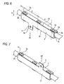
protector body 1 and alid 2 separately so that a wire harness can be passed through theprotector body 1 and then covered with thelid 2 thereby making a lock joining, as shown in Fig. 6. Meanwhile, thelid 2, a separate member, frequently is projected with a vehicle-fixing bracket 3 opened with abolt hole 3a for fixing the protector on a fixed member, such as a vehicle body panel. - Lock parts are provided on the
protector body 1 andlid 2 made separate as in the above. Lock-clawengaging frames 1c project with a required spacing along outer-surface upper ends of bothsidewalls 1a, 1b of theprotector body 1 while lockpieces 2b, having lockclaws 2a projecting down, project at widthwise both ends S1, S2 of thelid 2.
In this case, the lock-clawengaging frames 1c are provided at an equal pitch P in a lengthwise direction. Those are provided naturally at the equal pitch P lengthwise to thelock pieces 2b to be lock-joined with the lock-clawengaging frames 1c. Moreover, the lock-clawengaging frames 1c of theprotector body 1 and thelock pieces 2b of thelid 2 are provided in opposite positioned to each other with respect to a widthwise direction X. - Accordingly, even in case the
lid 2 is covered incorrectly widthwise onto theprotector body 1 as shown in Fig. 7, thelock claws 2a oflid 2 can be lock-joined with the lock-clawengaging frames 1c ofprotector body 1. However, when thelid 2 inverse widthwise, the vehicle-engaging bracket 3 in an incorrect mount position shown in Fig. 7 is directed upward X2 relative to the positioning of the vehicle-engaging bracket 3 directed downward X1 in the regular mount position shown in Fig. 7.
Accordingly, when fixing the protector onto a vehicle body, the bolt hole in the vehicle-engaging bracket 3 does not position on a vehicle panel side, posing a problem that the protector is not to be fixed on the vehicle panel. - It is an object thereof that, where there is a lid to be covered on and lock-joined with the protector body so that the lid can be projected with a vehicle fixing bracket, the lid is prevented from being attached incorrectly inverse widthwise on the protector body whereby the vehicle fixing bracket provided on the lid is provided projecting in a protector regular position this avoiding a situation not to be fixed onto a fixing member, such as a vehicle body panel.
- According to one aspect of the invention, there is provided a protector being outwardly attached to a wire harness disposed on a vehicle, the protector including: a protector body having a substantial trough shape, the protector body having both side walls being opposed to with each other so as to sandwich the wire harness therebetween; and a lock-claw engaging frame being projected from the protector body, the lock-claw engaging frame being provided on both side walls of the protector body which are along a width direction of the protector, the lock-claw engaging frame being provided at a first predetermined distance along a length direction of the protector body; and a lid attachable on the protector body after the wire harness has passed through the protector body, the lid having: a lock piece being downwardly projected from the lid, the lock piece having a lock-claw engageable with the lock-claw engaging frame, the lock piece of the lid being provided on both ends of the lid along a width direction of the lid, the lock piece of the lid being provided at a different predetermined distance from the first predetermined distance along a length direction of the lid, the lid having a vehicle fixing bracket projected from either one end of both ends of the lid along the width direction of the lid. The lid is not locked to the protector body by the lock piece of the lid and the lock-claw engaging frame of the protector body, when the lid is incorrectly assembled to the protector body in the width direction of the lid. The vehicle-fixing bracket is arranged in a regular direction.
- According to the above-structure, in case that the lock pieces and lock-claw engaging frames on widthwise both sides of the lid and protector body are mutually deviated in spacing, the lock pieces of the lid and the lock-claw engaging frames are not matched in respective position even when the lid is covered incorrectly widthwise onto the protector body. Thus, the lid is prevented from being locked with the protector body. Accordingly, the operator allows to aware the lid is attached in an incorrect direction to rearrange the lid into a correct regular position. The lid can be locked to the protector body.
Incidentally, in case the lid lock piece and the protector-body lock-claw engaging frame are in positions of point symmetry about a lengthwise center when those are incorrect widthwise, the lid lock piece and the protector-body lock-claw engaging frame are matched in position even when reverse widthwise. Accordingly, in order to provide a setting not for locking when the lid is put incorrectly widthwise, arrangement is not in point symmetry with the left and right lock piece and lock-claw-engaging frame. - According to another aspect of the invention, a lock-claw engaging frame of the protector body is provided at a front-rear opposite positions around a vicinity of both ends of the protector body in the length direction of the protector body. A lock piece of the lid is provided at a front rear opposite portions around a vicinity of both ends of the lid. The lock-claw engaging frame of the protector body is arranged to be displaced in the length direction of the protector body in an intermediate portion of the protector body. The lock piece of the lid is arranged to be displaced in the length direction of the lid in an intermediate portion of the lid.
By thus-configuration, on the protector, in case the lid is locked with the protector body particularly at lengthwise both ends and their around, the lid is not easily detached from the protector body by an external interfering member. At the lengthwise both ends, lock pieces and lock-claw engaging frames are arranged in opposite positions with respect to a front-rear widthwise direction. Accordingly, the left-and-right-pitch change point is taken at a lengthwise intermediate position. - According to another aspect of the invention, when the lid is incorrectly assemble to the protector body to be inverted in the width direction of the lid, the lock-claw is positioned to be interfered with a frame portion of the lock-claw engaging frame of the protector body.
By thus configuration, when the lock piece interferes with the lock-claw engager, the lid lock piece abuts against the protector-body lock-claw engaging frame into a state the opening is not closed tightly. Hence, the operator is allowed to aware that the lid is in an incorrect direction. - According to the above-aspects of the invention, in case the lid is put incorrect widthwise when attaching the separately-provided lid to the protector body in a manner closing the opening thereof, lock-joining is not effected because of mismatch in position between the lid and the protector body. The operator is allowed to be aware that the lid is in an incorrect direction, and to lock-join the lid and the protector body together after changing the lid into the regular direction.
Accordingly, the vehicle-fixing bracket projecting from the lid can be provided projecting to the regular position, thus preventing against being aware of incorrect lid direction for the first time upon fixing to a vehicle body panel, etc. - [0021]
- Fig. 1 is a perspective view of a protector in a first embodiment of the present invention.
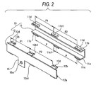
- Fig. 2 is an exploded perspective view of a protector body and lid of the protector according to the first embodiment.
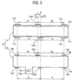
- Fig. 3 shows a positional relationship between the lock-claw engaging frames of protector main body of the protector and the lock pieces of the lid according to the first embodiment.
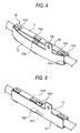
- Fig. 4 is a perspective view showing the case that the lid is incorrect in direction according to the first embodiment.
- Fig. 5 shows a modification of the first embodiment.
- Fig. 6 is a perspective view showing a related art.
- Fig. 7 is a perspective view showing a problem in the related art.
- With reference to the drawings, an embodiment of the present invention will now be explained.
Figs. 1 to 4 show aprotector 10 in a first embodiment. Theprotector 10 is made up by aprotector body 11 in a trough form formed of a resin-molded product, and alid 12 closing an opening of theprotector body 11. In this embodiment, the opening in theprotector body 11 is directed laterally so that thelid 12 can be arranged vertical at one side in a manner closing the opening and lock-joined to theprotector body 11, as shown in Fig. 1. - As shown in Figs. 2 and 3, lock-claw
engaging frames front side wall 11a andback side wall 11b which are opposite to with each other in a width direction of theprotector body 11.
Theframes
Incidentally, in the first embodiment shown in Fig. 1, the lock-clawengaging frames front wall 11a and therear wall 11b are respectively arranged with the lock-clawengaging frames protector body 11. The lock-claw engaging frame protector body 11. However, the lock-claw engaging frames 11c1, 11d1 positioned at intermediate position of the length direction of theprotector body 11 are not opposed in the front-and-rear widthwise direction of theprotector body 11, but are arranged to be displaced in the length direction of theprotector body 11. - As for the front lock-claw engaging frame 11c1, with reference to Fig. 3, the front lock-claw engaging frame 11c1 has a length "L". A center position of the front lock-claw engaging frame 11c1 in a direction thereof coincides with a center position "O" with respect to a lengthwise of the
protector body 11. Accordingly, in Fig. 3, a distance defined as "P" between a font lock-claw engaging frame 11c on a left side and the lock-claw engaging frame 11c1 is equal to a distance between the center lock-claw engaging frame 11c1 and the lock-claw engaging frame 11c on a right side.
As for the rear lock-claw engaging frame 11d1, with reference to Fig. 3, the rear lock-claw engaging frame 11d1 is provided deviated 1/2L leftward with respect to the center point O. Accordingly, there is a difference of 1/2L between a distance P1 between the lock-claw engaging frame 11d on the left side and the center lock-claw engaging frame 11d1 and a distance P2 between the lock-claw engaging frame 11d on right side and the center lock-claw engaging frame 11d1. - The
lid 12 has a plate shape to close an upper opening of theprotector body 11. lockpieces lid 12. the lock pieces are provided at front-and-rear both ends of the lid in a width direction of the lid with a predetermined distance in a length direction of the lid. Thelock pieces lock claws
Thelock pieces claw engaging frames protector body 11. - The lock pieces 12a1 and 12b1 positioned at intermediate positions in the direction of the lid are not opposed in a front-rear direction of the lid, but deviated in lengthwise positions. The front lock piece 12a1 is arranged in an opposite position to the front lock-claw engaging frame 11c1 while the rear lock piece 12b1 is arranged in an opposite position to the rear lock-claw engaging frame 11d1. Accordingly, the front lock piece 12a1 is matched with the lengthwise center O while the rear lock piece 12b1 is deviated 1/2L leftward. The distances to the left and right are differently given P1 and P2 similarly to the lock-claw engaging frames of the protector body.
- Meanwhile, the
lid 12 is projected with a plate-formedbracket 15 for fixing to the vehicle, between thefront lock piece 12a at lengthwise one end and the intermediate lock piece 12a1. The vehicle-fixingbracket 15 is opened with abolt hole 15a. The vehicle-fixingbracket 15, when mounted onto a vehicle body into an arrangement shown in Fig. 1, is placed projecting downward out of the lower end of thelid 12. - With the above structure of
protector 10, in case taking, as a regular direction, the front-rear widthwise of thelid 12 to be attached to theprotector body 11, the front lock piece 12a1 at the intermediate position of thelid 12 and the lock-claw engaging frame 11c1 of theprotector body 11 are in coincident opposite positions while the rear lock piece 12b1 and the lock-claw engaging frame 11d1 are in coincident opposite positions. Because the lid lock pieces at lengthwise both ends and the lock-claw engaging frames of protectormain body 11 are also in opposite positions, thelid 12 can be lock-joined to theprotector body 11. In this state, the vehicle-fixingbracket 15 projects in the regular direction from thelid 12. - Meanwhile, in the case to assemble the
lid 12 reverse in its front-rear width onto theprotector body 11, the lock piece 12a1 oflid 12 at its lengthwise one end becomes a state interfering with and getting onto a frame end of the lock-claw engaging frame 11d1 ofprotector body 11. Likewise, the lock piece 12b1 also becomes a state interfering with and getting onto the lock-claw engaging frame 11c1. Accordingly, thelid 12 at its center warps outward thus making it impossible to provide a close arrangement onto the opening of theprotector body 11. This allows the operator to be aware that the lid is in an incorrect direction. - Fig. 5 shows a modification. When the lock piece 12a1', 12b1' at intermediate position and the lock-claw engaging frame at intermediate position of the protector body 11' are assembled in incorrect direction of
lid 12' onto the protector body 11', in the case there is no mutual interference between the lock piece 12a1' and the lock-claw engaging frame 11d1' and also between 12b1' and 11c1', the lock-claw engaging frames of the protector body 11' are not in positions of the lock pieces 12a1', 12b1', thus not allowing for lock joining. Accordingly, the operator is allowed to be aware of incorrect direction.
Claims (3)
- A protector being outwardly attached to a wire harness disposed on a vehicle, the protector comprising:a protector body having a substantial trough shape, the protector body having both side walls being opposed to with each other so as to sandwich the wire harness therebetween; and a lock-claw engaging frame being projected from the protector body, the lock-claw engaging frame being provided on both side walls of the protector body which are along a width direction of the protector, the lock-claw engaging frame being provided at a first predetermined distance along a length direction of the protector body; anda lid attachable on the protector body after the wire harness has passed through the protector body, the lid having: a lock piece being downwardly projected from the lid, the lock piece having a lock-claw engageable with the lock-claw engaging frame, the lock piece of the lid being provided on both ends of the lid along a width direction of the lid, the lock piece of the lid being provided at a different predetermined distance from the first predetermined distance along a length direction of the lid, the lid having a vehicle fixing bracket projected from either one end of both ends of the lid along the width direction of the lid,
wherein the lid is not locked to the protector body by the lock piece of the lid and the lock-claw engaging frame of the protector body, when the lid is incorrectly assembled to the protector body in the width direction of the lid, and
wherein the vehicle-fixing bracket is arranged in a regular direction. - A protector according to claim 1, wherein a lock-claw engaging frame of the protector body is provided at a front-rear opposite positions around a vicinity of both ends of the protector body in the length direction of the protector body,
wherein a lock piece of the lid is provided at a front rear opposite portions around a vicinity of both ends of the lid,
wherein the lock-claw engaging frame of the protector body is arranged to be displaced in the length direction of the protector body in an intermediate portion of the protector body, and
wherein the lock piece of the lid is arranged to be displaced in the length direction of the lid in an intermediate portion of the lid. - A protector according to claim 1, wherein when the lid is incorrectly assemble to the protector body to be inverted in the width direction of the lid, the lock-claw is positioned to be interfered with a frame portion of the lock-claw engaging frame of the protector body.
Applications Claiming Priority (1)
| Application Number | Priority Date | Filing Date | Title |
|---|---|---|---|
| JP2004251664A JP4275599B2 (en) | 2004-08-31 | 2004-08-31 | Protector |
Publications (3)
| Publication Number | Publication Date |
|---|---|
| EP1630042A2 true EP1630042A2 (en) | 2006-03-01 |
| EP1630042A3 EP1630042A3 (en) | 2006-03-08 |
| EP1630042B1 EP1630042B1 (en) | 2008-08-27 |
Family
ID=35432540
Family Applications (1)
| Application Number | Title | Priority Date | Filing Date |
|---|---|---|---|
| EP05018828A Expired - Lifetime EP1630042B1 (en) | 2004-08-31 | 2005-08-30 | Protector |
Country Status (4)
| Country | Link |
|---|---|
| US (1) | US7214879B1 (en) |
| EP (1) | EP1630042B1 (en) |
| JP (1) | JP4275599B2 (en) |
| DE (1) | DE602005009297D1 (en) |
Families Citing this family (19)
| Publication number | Priority date | Publication date | Assignee | Title |
|---|---|---|---|---|
| JP4596430B2 (en) * | 2006-04-20 | 2010-12-08 | 矢崎総業株式会社 | Split protector connection fitting structure |
| JP4762969B2 (en) * | 2007-12-12 | 2011-08-31 | 古河電気工業株式会社 | Electrical connection box for mounting on vehicle and connection structure between electrical connection box unit and electronic control unit in electrical connection box for mounting on vehicle |
| US7798566B2 (en) * | 2007-12-14 | 2010-09-21 | Toyota Motor Engineering & Manufacturing North America, Inc. | Molded headliner reinforcement |
| JP5246618B2 (en) * | 2008-10-15 | 2013-07-24 | 株式会社フジクラ | Electrical component protector and its mounting structure |
| JP5983524B2 (en) * | 2013-05-08 | 2016-08-31 | 住友電装株式会社 | Protector and connected protector |
| JP5704195B2 (en) * | 2013-07-01 | 2015-04-22 | 株式会社オートネットワーク技術研究所 | Protector and wire harness with protector |
| JP2016131423A (en) * | 2015-01-13 | 2016-07-21 | 株式会社オートネットワーク技術研究所 | Wire protection member, wire harness with wire protection member, and slide wiring device |
| JP2016185023A (en) * | 2015-03-26 | 2016-10-20 | 住友電装株式会社 | Protector and wiring module with protector |
| DE102015110546A1 (en) * | 2015-06-30 | 2017-01-05 | Vibracoustic Gmbh | stop device |
| US10214161B2 (en) | 2015-07-06 | 2019-02-26 | Sumitomo Wiring Systems, Ltd. | Wire housing protector |
| USD761209S1 (en) | 2015-09-25 | 2016-07-12 | Sumitomo Wiring Systems, Ltd. | Wire harness protector |
| JP1548601S (en) | 2015-09-25 | 2016-05-09 | ||
| JP1548602S (en) | 2015-09-25 | 2016-05-09 | ||
| JP1548600S (en) | 2015-09-25 | 2016-05-09 | ||
| USD777115S1 (en) | 2015-09-25 | 2017-01-24 | Sumitomo Wiring Systems, Ltd. | Wire harness protector |
| USD786198S1 (en) | 2015-09-25 | 2017-05-09 | Sumitomo Wiring Systems, Ltd. | Wire harness protector |
| JP6439662B2 (en) * | 2015-11-18 | 2018-12-19 | 住友電装株式会社 | Protector |
| CA2950839C (en) * | 2016-01-30 | 2023-09-12 | Cooper Technologies Company | Equipment rack and components thereof |
| JP7008260B2 (en) | 2017-09-15 | 2022-01-25 | 住友電装株式会社 | Wire harness |
Citations (1)
| Publication number | Priority date | Publication date | Assignee | Title |
|---|---|---|---|---|
| JPH0686426A (en) | 1992-09-03 | 1994-03-25 | Yazaki Corp | How to lock the protector |
Family Cites Families (5)
| Publication number | Priority date | Publication date | Assignee | Title |
|---|---|---|---|---|
| JPH0419938Y2 (en) * | 1987-12-17 | 1992-05-07 | ||
| JPH0237515U (en) * | 1988-08-30 | 1990-03-13 | ||
| DE4204187C2 (en) * | 1992-02-13 | 1993-12-02 | Raymond A Gmbh & Co Kg | Cable duct for receiving cable bundles |
| JP2806225B2 (en) * | 1993-09-10 | 1998-09-30 | 住友電装株式会社 | Thermoplastic resin molded article and method for producing the same |
| US5597980A (en) * | 1994-11-30 | 1997-01-28 | Yazaki Corporation | Detachable mounting mechanism for a fuel injector wiring harness cover |
-
2004
- 2004-08-31 JP JP2004251664A patent/JP4275599B2/en not_active Expired - Fee Related
-
2005
- 2005-08-30 DE DE602005009297T patent/DE602005009297D1/en not_active Expired - Lifetime
- 2005-08-30 US US11/213,965 patent/US7214879B1/en not_active Expired - Fee Related
- 2005-08-30 EP EP05018828A patent/EP1630042B1/en not_active Expired - Lifetime
Patent Citations (1)
| Publication number | Priority date | Publication date | Assignee | Title |
|---|---|---|---|---|
| JPH0686426A (en) | 1992-09-03 | 1994-03-25 | Yazaki Corp | How to lock the protector |
Also Published As
| Publication number | Publication date |
|---|---|
| EP1630042B1 (en) | 2008-08-27 |
| EP1630042A3 (en) | 2006-03-08 |
| JP4275599B2 (en) | 2009-06-10 |
| JP2006074845A (en) | 2006-03-16 |
| US7214879B1 (en) | 2007-05-08 |
| DE602005009297D1 (en) | 2008-10-09 |
| US20070089895A1 (en) | 2007-04-26 |
Similar Documents
| Publication | Publication Date | Title |
|---|---|---|
| EP1630042B1 (en) | Protector | |
| EP2128946B1 (en) | Protector for wire harness | |
| US7586038B2 (en) | Electrical junction box and assembling method thereof | |
| US7544887B2 (en) | Electrical junction box | |
| JP3410951B2 (en) | Electrical junction box | |
| US8410361B2 (en) | Electrical junction box | |
| US6062633A (en) | Harness assembling structure on vehicle floor | |
| EP2085550B1 (en) | Hinge structure for vehicle open/close body | |
| KR20070098666A (en) | How to Mount Connector Joints, Clamping Members, and Connector Joints | |
| EP1630327B1 (en) | Vehicle door with door handle | |
| US20070267315A1 (en) | Case | |
| JPH0662718U (en) | Protector for wire harness | |
| US7075006B2 (en) | Electrical junction box | |
| JP6914823B2 (en) | Electrical junction box | |
| JP3376945B2 (en) | Electrical junction box | |
| JP4486589B2 (en) | Harness protector | |
| WO2007100122A1 (en) | Lamp protection cover mounting structure | |
| US20170028944A1 (en) | Cable guide attachment structure | |
| JP7833922B2 (en) | Exterior components | |
| JP5030508B2 (en) | Electrical junction box mounting structure | |
| JP4033124B2 (en) | Wiring harness routing structure for vehicles | |
| CN218754651U (en) | Bottom installation mould pressing floor | |
| JP7600911B2 (en) | Pull handle cap mounting structure | |
| CN210530545U (en) | Automobile tail door lock cover, automobile tail door and automobile | |
| JPH057093Y2 (en) |
Legal Events
| Date | Code | Title | Description |
|---|---|---|---|
| PUAI | Public reference made under article 153(3) epc to a published international application that has entered the european phase |
Free format text: ORIGINAL CODE: 0009012 |
|
| PUAL | Search report despatched |
Free format text: ORIGINAL CODE: 0009013 |
|
| AK | Designated contracting states |
Kind code of ref document: A2 Designated state(s): AT BE BG CH CY CZ DE DK EE ES FI FR GB GR HU IE IS IT LI LT LU LV MC NL PL PT RO SE SI SK TR |
|
| AX | Request for extension of the european patent |
Extension state: AL BA HR MK YU |
|
| AK | Designated contracting states |
Kind code of ref document: A3 Designated state(s): AT BE BG CH CY CZ DE DK EE ES FI FR GB GR HU IE IS IT LI LT LU LV MC NL PL PT RO SE SI SK TR |
|
| AX | Request for extension of the european patent |
Extension state: AL BA HR MK YU |
|
| 17P | Request for examination filed |
Effective date: 20060907 |
|
| 17Q | First examination report despatched |
Effective date: 20061017 |
|
| AKX | Designation fees paid |
Designated state(s): DE FR GB |
|
| GRAP | Despatch of communication of intention to grant a patent |
Free format text: ORIGINAL CODE: EPIDOSNIGR1 |
|
| GRAS | Grant fee paid |
Free format text: ORIGINAL CODE: EPIDOSNIGR3 |
|
| GRAA | (expected) grant |
Free format text: ORIGINAL CODE: 0009210 |
|
| AK | Designated contracting states |
Kind code of ref document: B1 Designated state(s): DE FR GB |
|
| REG | Reference to a national code |
Ref country code: GB Ref legal event code: FG4D |
|
| REF | Corresponds to: |
Ref document number: 602005009297 Country of ref document: DE Date of ref document: 20081009 Kind code of ref document: P |
|
| PLBE | No opposition filed within time limit |
Free format text: ORIGINAL CODE: 0009261 |
|
| STAA | Information on the status of an ep patent application or granted ep patent |
Free format text: STATUS: NO OPPOSITION FILED WITHIN TIME LIMIT |
|
| 26N | No opposition filed |
Effective date: 20090528 |
|
| REG | Reference to a national code |
Ref country code: FR Ref legal event code: PLFP Year of fee payment: 11 |
|
| PGFP | Annual fee paid to national office [announced via postgrant information from national office to epo] |
Ref country code: GB Payment date: 20150826 Year of fee payment: 11 Ref country code: DE Payment date: 20150825 Year of fee payment: 11 |
|
| PGFP | Annual fee paid to national office [announced via postgrant information from national office to epo] |
Ref country code: FR Payment date: 20150629 Year of fee payment: 11 |
|
| REG | Reference to a national code |
Ref country code: DE Ref legal event code: R119 Ref document number: 602005009297 Country of ref document: DE |
|
| GBPC | Gb: european patent ceased through non-payment of renewal fee |
Effective date: 20160830 |
|
| REG | Reference to a national code |
Ref country code: FR Ref legal event code: ST Effective date: 20170428 |
|
| PG25 | Lapsed in a contracting state [announced via postgrant information from national office to epo] |
Ref country code: GB Free format text: LAPSE BECAUSE OF NON-PAYMENT OF DUE FEES Effective date: 20160830 Ref country code: DE Free format text: LAPSE BECAUSE OF NON-PAYMENT OF DUE FEES Effective date: 20170301 Ref country code: FR Free format text: LAPSE BECAUSE OF NON-PAYMENT OF DUE FEES Effective date: 20160831 |