EP1629954A1 - Method of and system for controlling calender roll gap - Google Patents
Method of and system for controlling calender roll gap Download PDFInfo
- Publication number
- EP1629954A1 EP1629954A1 EP05107645A EP05107645A EP1629954A1 EP 1629954 A1 EP1629954 A1 EP 1629954A1 EP 05107645 A EP05107645 A EP 05107645A EP 05107645 A EP05107645 A EP 05107645A EP 1629954 A1 EP1629954 A1 EP 1629954A1
- Authority
- EP
- European Patent Office
- Prior art keywords
- internal passages
- heat transfer
- calender system
- gauge
- rollers
- Prior art date
- Legal status (The legal status is an assumption and is not a legal conclusion. Google has not performed a legal analysis and makes no representation as to the accuracy of the status listed.)
- Granted
Links
- 238000000034 method Methods 0.000 title claims abstract description 16
- 238000004891 communication Methods 0.000 claims abstract description 6
- 239000012530 fluid Substances 0.000 claims abstract description 5
- 238000010438 heat treatment Methods 0.000 claims description 7
- 239000007795 chemical reaction product Substances 0.000 claims description 4
- 239000013529 heat transfer fluid Substances 0.000 claims description 4
- 238000003490 calendering Methods 0.000 abstract description 7
- 238000001816 cooling Methods 0.000 description 3
- 239000000463 material Substances 0.000 description 2
- 230000002411 adverse Effects 0.000 description 1
- 230000001419 dependent effect Effects 0.000 description 1
- 230000006698 induction Effects 0.000 description 1
- 238000003754 machining Methods 0.000 description 1
- 239000000047 product Substances 0.000 description 1
- 239000004753 textile Substances 0.000 description 1
- XLYOFNOQVPJJNP-UHFFFAOYSA-N water Substances O XLYOFNOQVPJJNP-UHFFFAOYSA-N 0.000 description 1
Images


Classifications
-
- D—TEXTILES; PAPER
- D21—PAPER-MAKING; PRODUCTION OF CELLULOSE
- D21G—CALENDERS; ACCESSORIES FOR PAPER-MAKING MACHINES
- D21G1/00—Calenders; Smoothing apparatus
- D21G1/002—Opening or closing mechanisms; Regulating the pressure
- D21G1/004—Regulating the pressure
-
- B—PERFORMING OPERATIONS; TRANSPORTING
- B29—WORKING OF PLASTICS; WORKING OF SUBSTANCES IN A PLASTIC STATE IN GENERAL
- B29C—SHAPING OR JOINING OF PLASTICS; SHAPING OF MATERIAL IN A PLASTIC STATE, NOT OTHERWISE PROVIDED FOR; AFTER-TREATMENT OF THE SHAPED PRODUCTS, e.g. REPAIRING
- B29C43/00—Compression moulding, i.e. applying external pressure to flow the moulding material; Apparatus therefor
- B29C43/22—Compression moulding, i.e. applying external pressure to flow the moulding material; Apparatus therefor of articles of indefinite length
- B29C43/24—Calendering
- B29C43/245—Adjusting calender parameters, e.g. bank quantity
-
- D—TEXTILES; PAPER
- D21—PAPER-MAKING; PRODUCTION OF CELLULOSE
- D21G—CALENDERS; ACCESSORIES FOR PAPER-MAKING MACHINES
- D21G1/00—Calenders; Smoothing apparatus
- D21G1/02—Rolls; Their bearings
- D21G1/0226—Bearings
-
- F—MECHANICAL ENGINEERING; LIGHTING; HEATING; WEAPONS; BLASTING
- F16—ENGINEERING ELEMENTS AND UNITS; GENERAL MEASURES FOR PRODUCING AND MAINTAINING EFFECTIVE FUNCTIONING OF MACHINES OR INSTALLATIONS; THERMAL INSULATION IN GENERAL
- F16C—SHAFTS; FLEXIBLE SHAFTS; ELEMENTS OR CRANKSHAFT MECHANISMS; ROTARY BODIES OTHER THAN GEARING ELEMENTS; BEARINGS
- F16C13/00—Rolls, drums, discs, or the like; Bearings or mountings therefor
Definitions
- the present invention relates in general to calender systems, and more specifically to calender systems having a fine gauge adjustment.
- Calendering systems are often used by manufacturers to process textiles, paper or rubber in various stages of the tire making process.
- Many prior art systems lack the capability to fine tune the gauge of the part being calendered.
- the control of the gauge is done through adjusting the distance between the centerlines of the calender rolls.
- One way to accomplish this is by varying the temperature of the calender rolls, by either heating or cooling the rolls.
- this method has the disadvantage of affecting the processing of the rubber by adversely moving away from the optimal roll temperature.
- Another method of controlling the gauge is by running a draw or by changing the draw so that one roll spins faster than the other roll.
- this method has the disadvantage of causing additional stress to the rubber, which contributes to distortion and snap back.
- Another method of controlling the gauge is by machining the calender roll to decrease its diameter, thereby increasing the gauge. This method is time consuming and costly, and can only increase the gauge of the part, not decrease it.
- the invention provides in a first aspect a calender system suitable for processing a product to produce a desired gauge thickness, which has a fine gauge adjustment.
- the calender system preferably comprises:
- the invention provides in another aspect a method of adjusting a calender system having two or more rollers.
- the method comprises the steps of:
- the calendering system comprises a frame including a lower frame 14, and an upper frame 16 mounted to the lower frame 14.
- the lower frame 14 includes a plurality of support legs 18.
- the upper frame 16 is connected to the lower frame 14 and includes two opposed end supports 20, such as end support plates, for supporting a pair of rollers 30.
- One of the end supports 20 is fixed to the upper frame 16, while the opposite end support is preferably slidably mounted to the upper frame, to allow for adjustment.
- Each end support 20 further comprises a pair of rotatable hubs 22 mounted in parallel alignment, which are aligned with the rotatable hubs on the opposed end support for supporting a roller 30.
- Each hub 22 is received in an end of the roller.
- One of the hubs 22 for each roller 30 is connected to a drive shaft (not shown) which is driven by a motor 34.
- Each roller 30 may be rotated in the same or opposite direction of the adjacent roller, and at the same or different speeds.
- each end support 20 comprises one or more internal passages 40 for circulating a heat transfer medium such as water.
- the one ore or more internal passages 40 further comprise an inlet 42 and an outlet 44, so that the heat transfer medium may be circulated in an open loop through the end support 20.
- the one or more internal passages 40 are preferably located between the two centers of the rollers 30.
- passages 40, 46 run in a first direction, while a second set of passages 48, 50 extend in a second direction different than the first direction.
- the passages are strategically placed so that the end support 20 is responsive to temperature changes, and that there is a minimal temperature gradient over the entire end support.
- the heat transfer medium may be heated or cooled to the desired temperature prior to circulation within the end supports. If it is desired to increase or decrease the gap distance D between the rollers 30, then the heat transfer medium may be heated or cooled, respectively.
- the end support contracts or expands due to the temperature change.
- the distance between the centers of the rolls also likewise contracts or expands, depending upon whether the heat transfer medium is cooling or heating the end support. Precise control of the gap distance may be achieved by controlling the temperature of the heat transfer medium.
- the temperature of the heat transfer medium is preferably controlled by a temperature control unit (not shown) which is in electrical communication with a control mechanism (not shown).
- the desired gap distance or gauge of the material may be programmed into the controller.
- An active feedback loop may be utilized by the controller to maintain the gauge of the material by slightly varying the temperature of the heat transfer fluid.
- the gauge of the component may be varied up to 0.015 inch.
- the change in the gap distance D has a linear relationship with the coefficient of thermal expansion and the change in temperature of the end support plate, and is represented by the equation below.
- Change in gap distance D ( inches ) ⁇ * L * ⁇ T , where:
- the end support 20 may be heated by any other devices known to those skilled in the art, such as dielectric heating, radiant heating, induction heating or any other heating or cooling method known to those skilled in the art.
- each end support 20 may be independently heated to different temperatures to counteract any undesired asymmetries in the produced part, or produce desired asymmetries in the produced part.
- one side of the machine may be slightly different than the other side of the machine due to build up of machine tolerances.
Landscapes
- Engineering & Computer Science (AREA)
- General Engineering & Computer Science (AREA)
- Mechanical Engineering (AREA)
- Casting Or Compression Moulding Of Plastics Or The Like (AREA)
- Paper (AREA)
Abstract
Description
- The present invention relates in general to calender systems, and more specifically to calender systems having a fine gauge adjustment.
- Calendering systems are often used by manufacturers to process textiles, paper or rubber in various stages of the tire making process. Many prior art systems lack the capability to fine tune the gauge of the part being calendered. Typically the control of the gauge is done through adjusting the distance between the centerlines of the calender rolls. One way to accomplish this is by varying the temperature of the calender rolls, by either heating or cooling the rolls. However, this method has the disadvantage of affecting the processing of the rubber by adversely moving away from the optimal roll temperature. Another method of controlling the gauge is by running a draw or by changing the draw so that one roll spins faster than the other roll. However, this method has the disadvantage of causing additional stress to the rubber, which contributes to distortion and snap back. Another method of controlling the gauge is by machining the calender roll to decrease its diameter, thereby increasing the gauge. This method is time consuming and costly, and can only increase the gauge of the part, not decrease it.
- Thus an improved method and apparatus is desired which allows the fine adjustment of the calender gap so that the gauge of the component can be adjusted.
- The invention provides in a first aspect a calender system suitable for processing a product to produce a desired gauge thickness, which has a fine gauge adjustment. The calender system preferably comprises:
- a first and second roller each having a first and second end mounted in opposed end supports, said end support each having an inlet and an outlet in fluid communication with one or more internal passages, wherein a heat transfer medium may be circulated through said one or more internal passages.
- The invention provides in another aspect a method of adjusting a calender system having two or more rollers. The method comprises the steps of:
- determining the desired gauge of the end product, determining the actual gauge of the end product, circulating a heat transfer fluid in one or more internal passages of the end supports or end support plates of the rollers, and adjusting the temperature of the heat transfer medium until the desired gauge has been reached.
- Dependent claims cover preferred embodiments of the invention.
- The invention will be described by way of example and with reference to the accompanying drawings in which:
- Figure 1 is a perspective view of a calendering system;
- Figure 2 is an end view of the end support of the upper frame of the calender system of Figure 1;
- Figure 3 is an end view of the end support of Figure 2;
- Figure 4 is a top view of the frame of Figure 2;
- Figure 5 is a side view of the end support of Figure 2; and
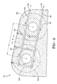
- Figure 6 is a cross-sectional view of the end support taken in the direction 6-6 of Figure 4.
- Turning to the drawings and in particular Figures 1-4, there is illustrated a calendering
system 10 embodying improvements especially suited for calendering rubber, although the invention is applicable to other applications. The calendering system comprises a frame including alower frame 14, and anupper frame 16 mounted to thelower frame 14. Thelower frame 14 includes a plurality ofsupport legs 18. Theupper frame 16 is connected to thelower frame 14 and includes twoopposed end supports 20, such as end support plates, for supporting a pair ofrollers 30. One of theend supports 20 is fixed to theupper frame 16, while the opposite end support is preferably slidably mounted to the upper frame, to allow for adjustment. Eachend support 20 further comprises a pair ofrotatable hubs 22 mounted in parallel alignment, which are aligned with the rotatable hubs on the opposed end support for supporting aroller 30. Eachhub 22 is received in an end of the roller. One of thehubs 22 for eachroller 30 is connected to a drive shaft (not shown) which is driven by amotor 34. Eachroller 30 may be rotated in the same or opposite direction of the adjacent roller, and at the same or different speeds. - Thus, there are two
rollers 30 mounted in parallel alignment, and spaced closely apart a gap distance D. The present invention concerns the fine adjustment of the gap distance D, by precise adjustment and control of the distance C located between the centers of therollers 30. In order to adjust the gap distance D, eachend support 20 comprises one or moreinternal passages 40 for circulating a heat transfer medium such as water. The one ore or moreinternal passages 40 further comprise aninlet 42 and anoutlet 44, so that the heat transfer medium may be circulated in an open loop through theend support 20. The one or moreinternal passages 40 are preferably located between the two centers of therollers 30. Preferably, there are two sets of passages located between the roll centers, wherein one set ofpassages passages end support 20 is responsive to temperature changes, and that there is a minimal temperature gradient over the entire end support. - The heat transfer medium may be heated or cooled to the desired temperature prior to circulation within the end supports. If it is desired to increase or decrease the gap distance D between the
rollers 30, then the heat transfer medium may be heated or cooled, respectively. As the heat transfer medium travels through the one or more internal passages, the end support contracts or expands due to the temperature change. As the end support contracts or expands, the distance between the centers of the rolls also likewise contracts or expands, depending upon whether the heat transfer medium is cooling or heating the end support. Precise control of the gap distance may be achieved by controlling the temperature of the heat transfer medium. - The temperature of the heat transfer medium is preferably controlled by a temperature control unit (not shown) which is in electrical communication with a control mechanism (not shown). The desired gap distance or gauge of the material may be programmed into the controller. An active feedback loop may be utilized by the controller to maintain the gauge of the material by slightly varying the temperature of the heat transfer fluid. Thus for example, by varying the temperature of the heat transfer medium from 80 to 160 degrees F, the gauge of the component may be varied up to 0.015 inch.
- The change in the gap distance D has a linear relationship with the coefficient of thermal expansion and the change in temperature of the end support plate, and is represented by the equation below.

- α is the coefficient of thermal expansion inch/(inch deg F)
- L is the distance between the centers of the
rollers 30, in inches - Δ T (deg F) is the change in temperature of the
end support 20. - In a second embodiment of the invention (not shown), the
end support 20 may be heated by any other devices known to those skilled in the art, such as dielectric heating, radiant heating, induction heating or any other heating or cooling method known to those skilled in the art. - In a third embodiment of the invention, each
end support 20 may be independently heated to different temperatures to counteract any undesired asymmetries in the produced part, or produce desired asymmetries in the produced part. For example, one side of the machine may be slightly different than the other side of the machine due to build up of machine tolerances.
Claims (10)
- A calender system having a fine gauge adjustment, wherein the calender system (10) comprises:a first and second roller (30) each having a first and second end mounted in opposed end supports (20), wherein at least one of said end supports (20) has an inlet (42) and an outlet (44) in fluid communication with one or more internal passages (40, 46), and wherein means for circulating a heat transfer medium through said one or more internal passages (40, 46) is provided.
- The calender system according to claim 1, wherein each of said end supports (20) has an inlet (42) and an outlet (44) in fluid communication with one or more internal passages (40, 46, 48, 50).
- The calender system of claim 1 or 2, wherein the first and second roller (30) each have a first and second end mounted in opposed first and second end supports (20), wherein each of said end supports (20) has an inlet (42) and an outlet (44) in fluid communication with one or more internal passages (40, 46, 48, 50), and wherein means for heating said first end support to a different temperature than said second end support is provided.
- The calender system of at least one of the previous claims, wherein the one or more internal passages (40, 46, 48, 50) are located between the centerlines of the first and second rollers (30).
- The calender system of at least one of the previous claims, further comprising a temperature control unit for controlling the temperature of the heat transfer fluid.
- The calender system of at least one of the previous claims, wherein the one or more internal passages (40, 46, 48, 50) are located between the rollers (30).
- The calender system of at least one of the previous claims, further comprising a plurality of internal passages (40, 46, 48, 50), wherein one of said passages is axially aligned in a first direction, while a second internal passage is axially aligned in a direction different than said first direction.
- A method of adjusting a calender system having two or more rollers (30), the method comprising the steps of: determining a desired gauge of an end product, determining an actual gauge of the end product, circulating a heat transfer fluid in one or more internal passages (40, 46, 48, 50) of at least one of end supports (20) of the rollers (30), adjusting the temperature of the heat transfer medium until the desired gauge has been reached.
- The method of claim 8, wherein the one or more internal passages (40, 46, 48, 50) are located between the centers of the rollers (30).
- The method of claim 8 or 9, wherein both end supports (20) have an internal passage (40, 46, 48, 50) for circulating a heat transfer medium, and wherein each end support (20) is heated to different temperatures.
Applications Claiming Priority (1)
| Application Number | Priority Date | Filing Date | Title |
|---|---|---|---|
| US10/924,535 US7431579B2 (en) | 2004-08-24 | 2004-08-24 | Calender gap control |
Publications (2)
| Publication Number | Publication Date |
|---|---|
| EP1629954A1 true EP1629954A1 (en) | 2006-03-01 |
| EP1629954B1 EP1629954B1 (en) | 2007-10-24 |
Family
ID=35276121
Family Applications (1)
| Application Number | Title | Priority Date | Filing Date |
|---|---|---|---|
| EP05107645A Expired - Lifetime EP1629954B1 (en) | 2004-08-24 | 2005-08-19 | Method of and system for controlling calender roll gap |
Country Status (7)
| Country | Link |
|---|---|
| US (2) | US7431579B2 (en) |
| EP (1) | EP1629954B1 (en) |
| JP (1) | JP4648799B2 (en) |
| CN (1) | CN1739936A (en) |
| BR (1) | BRPI0503423A (en) |
| DE (1) | DE602005002991T2 (en) |
| ES (1) | ES2296083T3 (en) |
Families Citing this family (6)
| Publication number | Priority date | Publication date | Assignee | Title |
|---|---|---|---|---|
| US7264477B1 (en) * | 2003-05-15 | 2007-09-04 | Mark Lloyd Hagan | Underwater drawing tablet |
| ATE426849T1 (en) * | 2004-12-29 | 2009-04-15 | Oce Tech Bv | TEMPERATURE CONTROL SYSTEM FOR BLADE SUPPORT PLATE OF A PRINTER |
| CN111002676A (en) | 2014-02-04 | 2020-04-14 | 古普里特·辛格·桑德哈 | Roofing membrane made of synthetic fiber fabric with anti-skid property |
| CN105538574A (en) * | 2015-09-09 | 2016-05-04 | 湖州格尔泰斯环保技术有限公司 | Adjustable polytetrafluoroethylene baseband calender |
| US11338608B2 (en) | 2018-11-12 | 2022-05-24 | Mark Lloyd Hagan | Tablet device for recording notes or markings in underwater or severe environment |
| US11691452B2 (en) | 2018-11-12 | 2023-07-04 | Mark Lloyd Hagan | Tablet device for underwater or severe environment |
Citations (6)
| Publication number | Priority date | Publication date | Assignee | Title |
|---|---|---|---|---|
| DE3014891A1 (en) * | 1980-04-17 | 1981-10-22 | Schwäbische Hüttenwerke GmbH, 7080 Aalen | Paper making machine or coating machine heated roller - has extra feeds to deliver heating medium to roller mantle end zones |
| US4503626A (en) * | 1981-10-12 | 1985-03-12 | Schwabische Huttenwerke Gmbh | Arrangement for manufacturing or treating web material |
| US4964202A (en) * | 1988-05-02 | 1990-10-23 | Kleinewefers Gmbh | Heatable roll for use in calenders and the like |
| US5101544A (en) * | 1988-10-15 | 1992-04-07 | Eduart Kusters Maschinenfabrik GmbH & Co. KG | Apparatus and method for regulating temperature in a flexure-controllable roll |
| DE4209712A1 (en) * | 1992-03-25 | 1993-09-30 | Escher Wyss Gmbh | Dia. control of ends of deflection controlled rolls - uses temp. control of fluid supplied to hydrostatic deflecting bearings at roll ends |
| US6468461B1 (en) * | 1997-02-28 | 2002-10-22 | Chiba Machine Industry Corporation | Process for forming sheet products |
Family Cites Families (20)
| Publication number | Priority date | Publication date | Assignee | Title |
|---|---|---|---|---|
| US2424856A (en) * | 1945-05-10 | 1947-07-29 | Farrel Birmingham Co Inc | Calender |
| US2933760A (en) * | 1957-08-22 | 1960-04-26 | Heide Elmer J Von Der | Process and apparatus for obtaining rubber or plastic sheeting of uniform thickness at high temperatures |
| US3060843A (en) * | 1961-11-09 | 1962-10-30 | Beloit Iron Works | Calender stack deflection control |
| US3201962A (en) * | 1961-11-13 | 1965-08-24 | Charles F Hautau | Rolling mill position control |
| US3389588A (en) * | 1965-03-09 | 1968-06-25 | United States Steel Corp | Apparatus for controlling the position of work rolls |
| US3460015A (en) * | 1966-01-12 | 1969-08-05 | Hines & Ass E W | Positioning control system |
| US3936258A (en) * | 1974-01-30 | 1976-02-03 | Intercole Automation, Inc. | Calender |
| US4514161A (en) * | 1983-12-09 | 1985-04-30 | Usm Corporation | Hydraulic roll protection system |
| US4734229A (en) * | 1984-11-13 | 1988-03-29 | Entek Manufacturing Inc. | Method for calendering temperature-critical thermoplastic material using a two-phase heat transfer medium |
| US4757582A (en) * | 1985-04-01 | 1988-07-19 | Valmet Oy | Roll with heated mantle and method |
| US4787835A (en) * | 1987-01-27 | 1988-11-29 | Marshall And Williams Company | Nip indicator for casting machines |
| DE3838852C1 (en) * | 1988-11-17 | 1990-05-23 | J.M. Voith Gmbh, 7920 Heidenheim, De | |
| JPH07281Y2 (en) * | 1989-02-17 | 1995-01-11 | 三菱重工業株式会社 | Single facer |
| DE4011427A1 (en) * | 1990-04-09 | 1991-10-10 | Troester Maschf Paul | METHOD AND DEVICE FOR PRODUCING A SEALING PLATE ON A CALENDAR |
| US5513560A (en) * | 1995-01-05 | 1996-05-07 | The Goodyear Tire & Rubber Company | Quick changeover method and apparatus for calender apparatus |
| US6280548B1 (en) * | 1995-01-05 | 2001-08-28 | Goodyear Tire & Rubber | Method and apparatus for building a laminate and forming a carcass subassembly for a tire |
| EP0889776B1 (en) * | 1996-03-16 | 2000-07-12 | Brückner Maschinenbau GmbH | Method of controlling the nip of the rolls of a calender, and rotatably mounted roll for use in the method |
| FI2640U1 (en) * | 1996-03-22 | 1996-11-22 | Valmet Corp | Roller, especially a roller for a soft or super calender |
| US6330024B1 (en) * | 1996-09-05 | 2001-12-11 | The Goodyear Tire & Rubber Company | System and method for controlling the size of material banks in calenders, mills, and feed mills |
| JP3756611B2 (en) * | 1997-02-28 | 2006-03-15 | 千葉機械工業株式会社 | Method and device for correcting the position of a sleeve when using the sleeve |
-
2004
- 2004-08-24 US US10/924,535 patent/US7431579B2/en not_active Expired - Fee Related
-
2005
- 2005-08-15 BR BRPI0503423-0A patent/BRPI0503423A/en not_active IP Right Cessation
- 2005-08-19 ES ES05107645T patent/ES2296083T3/en not_active Expired - Lifetime
- 2005-08-19 DE DE602005002991T patent/DE602005002991T2/en not_active Expired - Fee Related
- 2005-08-19 EP EP05107645A patent/EP1629954B1/en not_active Expired - Lifetime
- 2005-08-24 CN CN200510097715.4A patent/CN1739936A/en active Pending
- 2005-08-24 JP JP2005242351A patent/JP4648799B2/en not_active Expired - Fee Related
-
2008
- 2008-09-23 US US12/199,223 patent/US7897075B2/en not_active Expired - Fee Related
Patent Citations (6)
| Publication number | Priority date | Publication date | Assignee | Title |
|---|---|---|---|---|
| DE3014891A1 (en) * | 1980-04-17 | 1981-10-22 | Schwäbische Hüttenwerke GmbH, 7080 Aalen | Paper making machine or coating machine heated roller - has extra feeds to deliver heating medium to roller mantle end zones |
| US4503626A (en) * | 1981-10-12 | 1985-03-12 | Schwabische Huttenwerke Gmbh | Arrangement for manufacturing or treating web material |
| US4964202A (en) * | 1988-05-02 | 1990-10-23 | Kleinewefers Gmbh | Heatable roll for use in calenders and the like |
| US5101544A (en) * | 1988-10-15 | 1992-04-07 | Eduart Kusters Maschinenfabrik GmbH & Co. KG | Apparatus and method for regulating temperature in a flexure-controllable roll |
| DE4209712A1 (en) * | 1992-03-25 | 1993-09-30 | Escher Wyss Gmbh | Dia. control of ends of deflection controlled rolls - uses temp. control of fluid supplied to hydrostatic deflecting bearings at roll ends |
| US6468461B1 (en) * | 1997-02-28 | 2002-10-22 | Chiba Machine Industry Corporation | Process for forming sheet products |
Also Published As
| Publication number | Publication date |
|---|---|
| EP1629954B1 (en) | 2007-10-24 |
| ES2296083T3 (en) | 2008-04-16 |
| CN1739936A (en) | 2006-03-01 |
| JP4648799B2 (en) | 2011-03-09 |
| DE602005002991T2 (en) | 2008-07-24 |
| BRPI0503423A (en) | 2006-04-11 |
| DE602005002991D1 (en) | 2007-12-06 |
| US7897075B2 (en) | 2011-03-01 |
| US7431579B2 (en) | 2008-10-07 |
| US20060043624A1 (en) | 2006-03-02 |
| US20090011068A1 (en) | 2009-01-08 |
| JP2006062364A (en) | 2006-03-09 |
Similar Documents
| Publication | Publication Date | Title |
|---|---|---|
| US7897075B2 (en) | Calender gap control | |
| EP1088644B1 (en) | Deformation correcting method and apparatus for sheet materials | |
| KR100943038B1 (en) | Drawing Machine of Sheet Shape | |
| US8115143B2 (en) | Thermal roll, and drying apparatus and method | |
| US5125948A (en) | Heat conditioning chamber | |
| KR20020029748A (en) | Improved flat glass annealing lehrs | |
| US6282923B1 (en) | Heating glass sheets in tempering furnace | |
| US4375283A (en) | Method of controlling tensions in continuous annealing furnace and system therefor | |
| CN120206870A (en) | Rolling device and rolling method | |
| CN111890619A (en) | Sectional heating system for plastic calendering roller and control method thereof | |
| KR20080074048A (en) | Stretch-leveling method and apparatus of metal strip | |
| US7752961B2 (en) | Device and method for driving a preheating roll assembly in a calender unit | |
| KR20010042534A (en) | Calender with magnetic device for adjusting the contact pressure between the rolls | |
| RU2358918C2 (en) | Method and unit to heat glass plates | |
| KR100446096B1 (en) | A method for polishing a papermaking web and a polishing apparatus using the method | |
| CN101189080B (en) | Shape detection device and method thereof | |
| US12363804B2 (en) | Induction heated roll apparatus | |
| KR0160397B1 (en) | Calendar for treating a paper web and process for its use | |
| JP2818749B2 (en) | Glossy finishing method for paper sheet and calendar for implementing the method | |
| US20080121122A1 (en) | Calender Unit for Producing and/or Processing Thin Films | |
| CN223778033U (en) | Substrate cold-hot alternative pretreatment device | |
| JP5473752B2 (en) | Temperature rising roll soaking method and apparatus | |
| JPH08270641A (en) | Heating roller device | |
| CN120481163B (en) | A PVC film calendering apparatus and its multi-axis collaborative processing method | |
| CN223802936U (en) | Three-roll calendering equipment |
Legal Events
| Date | Code | Title | Description |
|---|---|---|---|
| PUAI | Public reference made under article 153(3) epc to a published international application that has entered the european phase |
Free format text: ORIGINAL CODE: 0009012 |
|
| AK | Designated contracting states |
Kind code of ref document: A1 Designated state(s): AT BE BG CH CY CZ DE DK EE ES FI FR GB GR HU IE IS IT LI LT LU LV MC NL PL PT RO SE SI SK TR |
|
| AX | Request for extension of the european patent |
Extension state: AL BA HR MK YU |
|
| 17P | Request for examination filed |
Effective date: 20060901 |
|
| 17Q | First examination report despatched |
Effective date: 20061006 |
|
| AKX | Designation fees paid |
Designated state(s): DE ES FR |
|
| GRAP | Despatch of communication of intention to grant a patent |
Free format text: ORIGINAL CODE: EPIDOSNIGR1 |
|
| GRAS | Grant fee paid |
Free format text: ORIGINAL CODE: EPIDOSNIGR3 |
|
| GRAA | (expected) grant |
Free format text: ORIGINAL CODE: 0009210 |
|
| AK | Designated contracting states |
Kind code of ref document: B1 Designated state(s): DE ES FR |
|
| REF | Corresponds to: |
Ref document number: 602005002991 Country of ref document: DE Date of ref document: 20071206 Kind code of ref document: P |
|
| REG | Reference to a national code |
Ref country code: ES Ref legal event code: FG2A Ref document number: 2296083 Country of ref document: ES Kind code of ref document: T3 |
|
| ET | Fr: translation filed | ||
| PLBE | No opposition filed within time limit |
Free format text: ORIGINAL CODE: 0009261 |
|
| STAA | Information on the status of an ep patent application or granted ep patent |
Free format text: STATUS: NO OPPOSITION FILED WITHIN TIME LIMIT |
|
| 26N | No opposition filed |
Effective date: 20080725 |
|
| PGFP | Annual fee paid to national office [announced via postgrant information from national office to epo] |
Ref country code: ES Payment date: 20080821 Year of fee payment: 4 Ref country code: DE Payment date: 20080829 Year of fee payment: 4 |
|
| PGFP | Annual fee paid to national office [announced via postgrant information from national office to epo] |
Ref country code: FR Payment date: 20080807 Year of fee payment: 4 |
|
| REG | Reference to a national code |
Ref country code: FR Ref legal event code: ST Effective date: 20100430 |
|
| PG25 | Lapsed in a contracting state [announced via postgrant information from national office to epo] |
Ref country code: FR Free format text: LAPSE BECAUSE OF NON-PAYMENT OF DUE FEES Effective date: 20090831 Ref country code: DE Free format text: LAPSE BECAUSE OF NON-PAYMENT OF DUE FEES Effective date: 20100302 |
|
| REG | Reference to a national code |
Ref country code: ES Ref legal event code: FD2A Effective date: 20090820 |
|
| PG25 | Lapsed in a contracting state [announced via postgrant information from national office to epo] |
Ref country code: ES Free format text: LAPSE BECAUSE OF NON-PAYMENT OF DUE FEES Effective date: 20090820 |