EP1629643B1 - Device, method, and program for performing master/slave switching process - Google Patents
Device, method, and program for performing master/slave switching process Download PDFInfo
- Publication number
- EP1629643B1 EP1629643B1 EP04745622A EP04745622A EP1629643B1 EP 1629643 B1 EP1629643 B1 EP 1629643B1 EP 04745622 A EP04745622 A EP 04745622A EP 04745622 A EP04745622 A EP 04745622A EP 1629643 B1 EP1629643 B1 EP 1629643B1
- Authority
- EP
- European Patent Office
- Prior art keywords
- master
- information
- slave
- state change
- predetermined
- Prior art date
- Legal status (The legal status is an assumption and is not a legal conclusion. Google has not performed a legal analysis and makes no representation as to the accuracy of the status listed.)
- Expired - Lifetime
Links
Images




Classifications
-
- H—ELECTRICITY
- H04—ELECTRIC COMMUNICATION TECHNIQUE
- H04W—WIRELESS COMMUNICATION NETWORKS
- H04W72/00—Local resource management
- H04W72/50—Allocation or scheduling criteria for wireless resources
- H04W72/51—Allocation or scheduling criteria for wireless resources based on terminal or device properties
-
- H—ELECTRICITY
- H04—ELECTRIC COMMUNICATION TECHNIQUE
- H04W—WIRELESS COMMUNICATION NETWORKS
- H04W84/00—Network topologies
- H04W84/18—Self-organising networks, e.g. ad-hoc networks or sensor networks
- H04W84/20—Leader-follower arrangements
-
- H—ELECTRICITY
- H04—ELECTRIC COMMUNICATION TECHNIQUE
- H04L—TRANSMISSION OF DIGITAL INFORMATION, e.g. TELEGRAPHIC COMMUNICATION
- H04L12/00—Data switching networks
- H04L12/28—Data switching networks characterised by path configuration, e.g. LAN [Local Area Networks] or WAN [Wide Area Networks]
- H04L12/2803—Home automation networks
-
- H—ELECTRICITY
- H04—ELECTRIC COMMUNICATION TECHNIQUE
- H04L—TRANSMISSION OF DIGITAL INFORMATION, e.g. TELEGRAPHIC COMMUNICATION
- H04L12/00—Data switching networks
- H04L12/28—Data switching networks characterised by path configuration, e.g. LAN [Local Area Networks] or WAN [Wide Area Networks]
- H04L12/2803—Home automation networks
- H04L12/2807—Exchanging configuration information on appliance services in a home automation network
- H04L12/2814—Exchanging control software or macros for controlling appliance services in a home automation network
-
- H—ELECTRICITY
- H04—ELECTRIC COMMUNICATION TECHNIQUE
- H04L—TRANSMISSION OF DIGITAL INFORMATION, e.g. TELEGRAPHIC COMMUNICATION
- H04L12/00—Data switching networks
- H04L12/28—Data switching networks characterised by path configuration, e.g. LAN [Local Area Networks] or WAN [Wide Area Networks]
- H04L12/40—Bus networks
- H04L12/403—Bus networks with centralised control, e.g. polling
-
- H—ELECTRICITY
- H04—ELECTRIC COMMUNICATION TECHNIQUE
- H04L—TRANSMISSION OF DIGITAL INFORMATION, e.g. TELEGRAPHIC COMMUNICATION
- H04L41/00—Arrangements for maintenance, administration or management of data switching networks, e.g. of packet switching networks
-
- H—ELECTRICITY
- H04—ELECTRIC COMMUNICATION TECHNIQUE
- H04W—WIRELESS COMMUNICATION NETWORKS
- H04W72/00—Local resource management
- H04W72/50—Allocation or scheduling criteria for wireless resources
- H04W72/54—Allocation or scheduling criteria for wireless resources based on quality criteria
-
- H—ELECTRICITY
- H04—ELECTRIC COMMUNICATION TECHNIQUE
- H04L—TRANSMISSION OF DIGITAL INFORMATION, e.g. TELEGRAPHIC COMMUNICATION
- H04L12/00—Data switching networks
- H04L12/28—Data switching networks characterised by path configuration, e.g. LAN [Local Area Networks] or WAN [Wide Area Networks]
- H04L12/2803—Home automation networks
- H04L12/2807—Exchanging configuration information on appliance services in a home automation network
- H04L12/2809—Exchanging configuration information on appliance services in a home automation network indicating that an appliance service is present in a home automation network
-
- H—ELECTRICITY
- H04—ELECTRIC COMMUNICATION TECHNIQUE
- H04L—TRANSMISSION OF DIGITAL INFORMATION, e.g. TELEGRAPHIC COMMUNICATION
- H04L12/00—Data switching networks
- H04L12/28—Data switching networks characterised by path configuration, e.g. LAN [Local Area Networks] or WAN [Wide Area Networks]
- H04L12/2803—Home automation networks
- H04L2012/284—Home automation networks characterised by the type of medium used
- H04L2012/2841—Wireless
-
- H—ELECTRICITY
- H04—ELECTRIC COMMUNICATION TECHNIQUE
- H04W—WIRELESS COMMUNICATION NETWORKS
- H04W72/00—Local resource management
- H04W72/20—Control channels or signalling for resource management
Definitions
- the present invention relates to devices, methods, and programs for performing master/slave switching process. More specifically, the present invention relates to a master/slave switching method for use in a network system where a master device manages slave devices, a device that performs the method, and a program for performing the method.
- one device manages all of the other devices (hereinafter referred to as slave device) in order to prevent a conflict in data communication performed among the devices.
- the master device provides a transmission right to a slave device, relays data transmission and reception among the slave devices, etc.
- each device is provided in advance with a level for use in determining the master device.
- all of the connected devices are compared with one another based on their levels, and a device having the highest level determined as the master device.
- the master device manages the entire network system, processing load and power consumption of the master device are large compared with those of the slave device.
- most devices that incorporate a wireless communication technology, such as Bluetooth (R) are battery-powered portables, and therefore the amount of power consumption required for functioning as the master device is hardly negligible.
- the device having the highest level is always set as the master device irrespectively of a device' s state changing with time, such as the remaining amount of battery and the processing load.
- the master device is never switched unless another device having a higher level than the current master device is newly connected to the network. Therefore, when an inconvenience, such as battery exhaustion, occurs to the current master device, the network might be down.
- the master device is set in consideration of the state of each device as well as the performance of each device.
- the network system is a home network system in which home electric appliances are connected to one another, for example, the state of each home electric appliance is likely to vary depending on time of day and season. Therefore, the master device is preferably set in consideration of the state and performance of each device at the time of setting and also a change in the state of each device that is expected to occur afterward.
- Patent Abstracts of Japan, vol. 2000, no. 21, 3 August 2001 (2001-08-03 ) & JP 2001-103570 A (Toshiba Corp.), 13 April 2001 (2001-04-13) discloses a device having a master function for use in a network system in which a master device manages at least one slave device.
- the device comprises a device's own device information managing section operable to manage device's own device information which includes a predetermined information, regarding a change of the device; a schedule information managing section operable to manage schedule information indicative of master device candidates; a device information processing section operable, when the device operates as the master device, to specify a slave device from among a plurality of slave devices which are the master device candidates indicated by the schedule information and operable to obtain predetermined information regarding a state change of the specified slave device from the specified slave device; and a switch controlling section operable to compare the predetermined information regarding the state change of the specified slave device obtained by the device information processing section with a predetermined information regarding the state change of the device included in the device's own device information, and operable, when the state change of the specified slave device is smaller than the state change of the device, to switch between a master operation operated by the device and a slave operation operated by the specified slave device.
- a device's own device information managing section operable to manage device's own device information which includes a predetermined information,
- WO 01/03379 A1 describes a data transmission network, comprising a number of nodes which are set up to function optionally as a master or a slave.
- the master is in a position to command a slave which guarantees the best transmission quality to the remaining slaves, to take over the master function.
- XP-002198269 also refers to a similar data transmission network.
- An object of the present invention is to provide a device that performs a master/slave switching process for dynamically changing a device most suitable as a master device in a network in consideration of the performance and state of each device at the time of setting and also a change in the state of each device that are expected to occur afterwards a method of performing the master/slave switching process and a program therefore.
- the device according to the present invention includes a device's own device information managing section, an other device information managing section, a schedule information managing section, a device information processing section, and a switch controlling section.
- the device's own device information managing section manages device's own device information regarding its own device.
- the other device information managing section manages other device information regarding at least one another device connected to the network system, the other device information including at least availability of the master function.
- the schedule information managing section manages schedule information indicative of master device candidates by predetermined segment.
- the device information processing section specifies a slave device which is one of the master device candidates having the master function based on the other device information and the schedule information, and obtains predetermined information from the specified slave device.
- the switch controlling section controls switching between a master operation and a slave operation based on the predetermined information obtained by the device information processing section and the predetermined information included in the device's own device information.
- Typical examples of the predetermined time are a time when a device having the master function is newly connected to the network system, and a time when a change occurs to the device's own device information managed by the device's own device information managing section.
- the change of the device's own device information is preferably resource information required for the master operation, a reduction in a remaining amount of battery, or a deterioration in communication quality.
- the predetermined segment may be a segment of time of day or season.
- the switch controlling section transmits the other device information managed by the other device information managing section to a device newly performing the master operation.
- the master/slave switching method includes the steps of: specifying, at a predetermined time, a slave device which is one of master device candidates having a master function based on other device information including at least availability of the master function of other devices connected to a network and schedule information indicative of master device candidates by predetermined segment; obtaining predetermined information from the specified slave device; and controlling switching of a master operation and a slave operation based on the predetermined information obtained in the information obtaining step and predetermined information of device' s own device information of the device currently performing the master operation.
- the functional blocks forming the above-described device may be achieved by an LSI.
- the master/slave switching method may be provided in a form of a program for causing a computer to perform a series of processes. This program may be introduced to a computer as being recorded on a computer-readable recording medium.
- the device functioning as the master device is dynamically changed among the devices forming the network. With this, even if an inconvenience, such as battery exhaustion, occurs to the current master device, the current master device is switched to a new master device for maintaining the network. Also, even if the environment of the devices changes with time, it is possible to narrow down the most suitable master device candidate with the use of the schedule information. This reduces the load on the system caused by the master/slave switching process.
- FIG. 1 is an illustration showing the concept of a network configured by devices performing a master/slave switching process according to a first embodiment of the present invention.
- the network according to the first embodiment is configured by one master device being connected to one or more slave devices in a wired or wireless manner for intercommunication.
- FIG. 1 shows an example of the network in which a device 1 functioning as a master device manages devices 2 through 5 functioning as slave devices. Description is made below to a mixed network of devices having a master function for functioning as a master device and a slave function for functioning as a slave device and devices having only the slave function
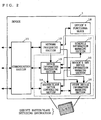
- FIG. 2 is a block diagram illustrating the detailed structure of the device 1, which is the master device in FIG. 1.
- the device 1 includes a communication section 11, a network processing section 12, a device information processing section 13, a master/slave switch controlling section 14, a device's own device information managing section 15, anotherdeviceinformation managing section 16, a schedule information managing section 17, and a device' s functional block 18.
- Each of the devices 2 through 5, which are the slave devices, has the same structure as that of FIG. 2 if they have the master function. If they do not have the master function, each of the devices 2 through 5 has a structure similar to that of FIG. 2, except that the master/slave switch controlling section 14 and the other device information managing section 16 are omitted.
- components included in a device i 1 to 5 are represented as a communication section i 1, a network processing section i 2, a device information processing section i 3, a master/slave switch controlling section i 4, a device's own device information managing section i 5, an other device information managing section i 6, a schedule information managing section i 7, and a device's functional block i 8.
- the communication section i 1 performs a predetermined communication with a communication section(s) j 1 ( j is any other than i ) of another device(s) j in response to instructions from the network processing section i 2, the device information processing section i 3 and the master/slave switch controlling section i 4.
- the network processing section i 2 performs a necessary process when its own device i or another device j newly participates in the network.
- the device information processing section i 3 performs an information obtaining process and an information comparing and determining process based on schedule information (which will be described further below) to determine whether a master/slave switching process is to be performed.
- the master/slave switch controlling section i 4 performs a predetermined switching process when the device information processing section i 3 determines that the master/slave switching process is to be performed.
- the device's own device information managing section i 5 stores and manages predetermined information (device's own device information) regarding the device i .
- the other device information managing section i 6 stores and manages predetermined information (other device information) regarding the device(s) j .
- the schedule information managing section i 7 stores and manages schedule information indicative of master device candidates by predetermined segment.
- the device's functional block i 8 is a section that performs primary functions of the device i. For example, if the device i is a television set, the device's functional block i 8 corresponds to a functional section for receiving a program and displaying the received program on a screen.
- the schedule information managed by the schedule information managing section i 7 is used for narrowing down master device candidates in performing a master/slave switching process. This schedule information is useful when the environment where devices are placed is changed with time, such as when the present invention is applied to a home network.
- the home network is assumed to include various home electric appliances connected to one another, such as information devices (personal computers, facsimile machines, etc.), audiovisual devices (televisions, video recorders, etc.), cooking devices (microwave ovens, refrigerators, etc.), and air-conditioning devices (coolers, fan heaters, etc.). Each type of such devices has its own time zone and season when the device is frequently used.
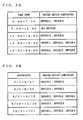
- FIG. 3A depicts a schedule divided into time zones. For example, in FIG. 3A, master device candidates in a time zone of 11:00 to 14:00 are the device 3 and the device 5.
- FIG. 3B depicts a schedule divided into seasons (dates). For example, in FIG. 3B, master device candidates from April 1 to June 20 are the device 2 and the device 3. Alternatively, the schedule information may have registered thereon devices not suitable as master devices.
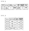
- FIG. 4 is an illustration showing one example of the device's own device information managed by the device's own device information managing section i 5. Note that not all items included in the device's own device information are required to be stored in the device's own device information managing section i 5, but it suffices that at least items that are referred to for the master/slave switching process, which will be described further below, are stored.
- the device's own device information includes items indicative of fixed performance of the device, such as its device ID, CPU power, and availability of the master function, and items indicative of variable states of the device, such as power supply type, the remaining amount of battery, and the device's condition.
- the device ID is identification information f or uniquely specifying the device.
- BD_Address corresponds to this device ID.
- the CPU power is represented by a type of the CPU and an operating clock frequency.
- Availability of the master function indicates whether the device has the master function (master process routine). Items other than the above included in the device's own device information are, for example, manufacturing date, standard price, rank set for each product.
- the power supply type indicates whether the device is powered by AC power supply or battery and, when powered by battery, indicates a type of battery (alkaline, lithium, etc).
- the remaining amount of battery indicates the remaining amount when the power supply type is battery. This remaining amount of battery may be represented by a ratio (%) of the remaining amount of battery to the maximum amount thereof or by an estimated remaining time for operation.
- the remaining amount of battery may be set to have a maximum value or a predetermined value other than the maximum value for distinction.
- the device's condition includes a power-applied time, a use time, a transmission output level, a time from reception of a request to transmission of a response (a response time), information indicative of whether the device is in a power-saving mode, a CPU running ratio for measuring a load on a CPU, and the like.
- FIG. 5 is an illustration showing one example of the other device information stored by the other device information managing section i 6. Note that the other device information is not restricted to the information depicted in FIG. 5, but may be freely set according to the information referred to when the master/slave switching process, which will be described further below, is performed.
- Examples of items included in the other device information are, as for each device j connected to the network as a slave device, a device ID (address), an operation mode (normal/power-saving), availability of the master function, the remaining amount of battery, and quality of communication between the device i and the device(s) j (error rate, electric field strength, etc).
- the master/slave switching process according to the present invention to be performed between the above-structured devices in the network shown in FIG. 1 is exemplarily described.
- description is made to the following two cases: one is that the master/slave switching process is performed upon participation of a new device in the network and the other is that the process is performed at other times.
- the master/slave switching process is performed based on the remaining amount of battery of each device.
- the master device 1 and the slave devices 2 through 5 have the device's own device information (FIG. 4) stored in the device's own device information managing section 15, 25, 35, 45, and 55, respectively. Furthermore, the master device 1 has the other device information regarding the slave devices 2 through 5 (FIG. 5) stored in the other device information managing section 16.
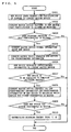
- the device information processing section 13 of the device 1 determines whether a predetermined time has come (step S1101).
- the predetermined time may be a predetermined time of day, a predetermined time interval, a time when the state of the device is changed, such as a time when a command is issued, a time when the remaining amount of battery is changed or a time when the communication quality is deteriorated, or a time when the processing load of the CPU is changed.
- the change of the remaining amount of battery can be easily detected by, for example, determining whether the remaining amount of battery is lower than a predetermined threshold.
- the degradation in communication quality can be easily detected by, for example, determining whether an error rate (frequency of occurrence of a retransmitting process) as to data received from each slave device has been increased or determining whether the electric field intensity has been attenuated.
- Examples of the time when a master/slave switching process unique to a home network is required are a time when a master video device starts preprogrammed recording and a time when a master facsimile machine starts receiving facsimile.
- the device information processing section 13 refers to the other device information stored in the other device information managing section 16 to extract devices having the master function (step S1102).
- the device information processing section 13 then refer to the schedule information managed by the schedule information managing section 17 to further extract only master device candidates from the devices extracted in step S1102 (step S1103).
- the device information processing section 13 transmits, to the extracted master device candidates, a request for the predetermined information required for determining whether to perform the master/slave switching process (in the present embodiment, a request for the remaining amount of battery) (step S1104).
- the device information processing section i 3 of each device i receiving the request for the remaining amount of battery extracts the information about the current remaining amount of battery from the device's own information managing section i 5, and then transmits the extracted information to the device 1 (step S1105).
- the device information processing section 13 stores the received remaining amount of battery in the other device information managing section 16, and also reports the received remaining amount of battery to the master/slave switch controlling section 14.
- the master/slave switch controlling section 14 extracts the information about the remaining amount of battery of each device i from the other device information managing section 16 and the information about the remaining amount of battery of the device 1 from the device's own device information managing section 15.
- the master /slave switch controlling section 14 compares all pieces of extracted information to determine whether a device that is more suitable as the master device than the device 1 is present, that is, whether a device whose performance as the master device is higher than that of the device 1 is present (step S1106). Specifically, the device whose ratio of the remaining amount is the largest or whose estimated remaining time for operation is the longest is determined as the device most suitable as the master device.
- the device 2 is determined as the device most suitable as the master device.
- a predetermined coefficient is set for each power supply type according to the priority order. Then, by adding the predetermined coefficient to the remaining amount of battery or by multiplying the remaining amount of battery by the predetermined coefficient, the device most suitable as the master device is determined (FIG. 12B). In this case, the device 3 is determined as the device most suitable as the master device. Determination to be made by using information other than the remaining amount of battery has been described above.
- the master/slave switch controlling section 14 of the device 1 Upon determination that a device that is more suitable (has a higher performance) as the master device than the device 1 is present, the master/slave switch controlling section 14 of the device 1 performs, in cooperation with the master/slave switch controlling section of the more suitable device, a master/slave switching process for causing the more suitable device to perform a master operation (steps S1107 and S1108).
- This master/slave switching process in step S1108 is performed basically in the above-described two ways (refer to FIGS. 7 through 10). However, the master/slave switching process in step S1108 is different from that shown in FIGS. 7 through 10 in the following point. That is, as shown in FIGS.
- the device 1 Upon receiving the response rejecting the request, the device 1 determines whether another slave device suitable as the master device is present (steps S1301 and S1401). If such a slave device is present, the device 1 again performs a master/slave switching process on this slave device (steps S1302 and S1402).
- the device functioning as the master device is dynamically changed among the devices forming the network.
- the current master device is switched to a new master device for maintaining the network.
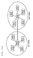
- FIG. 15A is an illustration showing the concept of a network configured by devices performing a master/slave switching process according to a second embodiment of the present invention.
- the network according to the second embodiment has the structure in which a first network and a second network, each of which includes one master device and one or more slave deices as described in the first embodiment, are connected to each other at their master devices.
- the wireless communication technology such as Bluetooth (R)
- the first network and the second network correspond to Piconets
- the network according to the second embodiment that includes these two networks corresponds to a Scatternet.
- a feature of the second embodiment is that the master/slave switching process is performed between the first network and the second network.
- the master devices of the first and second networks each perform the master function and the slave function simultaneously. This is because, when viewed from the master device of the first network, the master device of the second network is one of the slave devices and, when viewed from the master device of the second network, the master device of the first network is one of the slave devices.
- the master/slave switching process is performed on the relation between the master devices of the first and second networks.
- either one or both of the error rate and the electric field intensity are checked for all combinations of the devices included in the first and second networks.
- the schedule information is used together, the number of combinations of the devices can be reduced, thereby reducing the processing load on the system. Of these combinations, one combination of devices that is most suitable is then selected.
- the master/slave switching process is then performed in each of the first and second networks. Finally, a new master device in the first network after switching and a new master device in the second network after switching are connected to each other.
- a pair of devices, one in the first network and the other in the second network can be determined as the master devices.
- the device for performing the master/slave switching process of the second embodiment of the present invention even when a plurality of small networks are combined to form one large network, the effect of the first embodiment can be obtained.
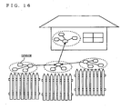
- a specific example is shown in FIG. 16, in which a plurality of security sensors (devices) for preventing crime form a several number of small networks, and these small networks further form a large network.
- each of the functional blocks of the device information processing section 13, the master/slave switch controlling section 14, the device's own device information managing section 15, the other device information managing section 16, and the schedule information managing section 17 are typically achieved by a large-scale integrated (LSI) circuit (called an IC, a system LSI, a super LSI, a ultra LSI, or the like, depending on the degree of integration) (refer to FIG. 2).
- LSI large-scale integrated circuit
- circuit integration is achieved not only by an LSI but also by a dedicated circuit or a general-purpose processor.
- a Field Programmable Gate Array FPGA
- FPGA Field Programmable Gate Array
- reconfigurable processor capable of reconfiguring the connection of circuit cells and the setting inside the LSI can be used.
- integration of the functional blocks can be performed by using a new circuit integration technology that would replace the LSI technology with the advance of the semiconductor technology or with the advent of another derivative technology.
- One possible technology that would be adapted for use is a biotechnological technique.
- the method of performing the master/slave switching process of the present invention is achieved by a CPU interpreting predetermined program data that is stored in a storage device (a ROM; a RAM, a hard disk, etc.) and is capable of causing the above-described processes to be performed.
- a storage device a ROM; a RAM, a hard disk, etc.
- the program data may be introduced through a recording medium to the storage device, or may be executed directly from the recording medium.
- the present invention can be used for a network system in which a master device manages slave devices, for example, and is particularly suitable when a device most suitable as the master device in the network system is dynamically changed in consideration of the performance and state of each device.
Landscapes
- Engineering & Computer Science (AREA)
- Computer Networks & Wireless Communication (AREA)
- Signal Processing (AREA)
- Automation & Control Theory (AREA)
- Quality & Reliability (AREA)
- Small-Scale Networks (AREA)
- Mobile Radio Communication Systems (AREA)
Description
- The present invention relates to devices, methods, and programs for performing master/slave switching process. More specifically, the present invention relates to a master/slave switching method for use in a network system where a master device manages slave devices, a device that performs the method, and a program for performing the method.
- In recent years, various technologies have been suggested for connecting a plurality of devices to form a network in which information stored in one device is used by another device and one device remotely controls another device. One example of such technologies is a technology using a PAN profile of Bluetooth (R).
- In general, in a network system formed by connecting a plurality of devices, one device (hereinafter referred to as a master device) manages all of the other devices (hereinafter referred to as slave device) in order to prevent a conflict in data communication performed among the devices. In this management, the master device provides a transmission right to a slave device, relays data transmission and reception among the slave devices, etc.
- In such a system in which the master device manages all of the slave devices, the communication performance in the entire network largely depends on the performance of the master device. Therefore, a technology has been suggested for automatically determining a device most suitable as the master device. In this conventional technology, each device is provided in advance with a level for use in determining the master device. When a new device is connected to the network, all of the connected devices are compared with one another based on their levels, and a device having the highest level determined as the master device.
- Now, since the master device manages the entire network system, processing load and power consumption of the master device are large compared with those of the slave device. Particularly, most devices that incorporate a wireless communication technology, such as Bluetooth (R), are battery-powered portables, and therefore the amount of power consumption required for functioning as the master device is hardly negligible. However, in the above-mentioned conventional technology, the device having the highest level is always set as the master device irrespectively of a device' s state changing with time, such as the remaining amount of battery and the processing load. Moreover, the master device is never switched unless another device having a higher level than the current master device is newly connected to the network. Therefore, when an inconvenience, such as battery exhaustion, occurs to the current master device, the network might be down.
- In order to get around the above problem, the master device is set in consideration of the state of each device as well as the performance of each device. However, when the network system is a home network system in which home electric appliances are connected to one another, for example, the state of each home electric appliance is likely to vary depending on time of day and season. Therefore, the master device is preferably set in consideration of the state and performance of each device at the time of setting and also a change in the state of each device that is expected to occur afterward.
- Patent Abstracts of Japan, vol. 2000, no. 21, 3 August 2001 (2001-08-03) &
JP 2001-103570 A -
WO 01/03379 A1 - Zhang W. et al.: "On Improving the Performance of Bluetooth Networks Through Dynamic Role Management", May 2001, (2001-05), XP-002198269 also refers to a similar data transmission network.
- An object of the present invention is to provide a device that performs a master/slave switching process for dynamically changing a device most suitable as a master device in a network in consideration of the performance and state of each device at the time of setting and also a change in the state of each device that are expected to occur afterwards a method of performing the master/slave switching process and a program therefore.
- This object is solved by the features of
claims claims 2 to 7. The device according to the present invention includes a device's own device information managing section, an other device information managing section, a schedule information managing section, a device information processing section, and a switch controlling section. - The device's own device information managing section manages device's own device information regarding its own device. The other device information managing section manages other device information regarding at least one another device connected to the network system, the other device information including at least availability of the master function. The schedule information managing section manages schedule information indicative of master device candidates by predetermined segment. When the device operates as the master device, the device information processing section specifies a slave device which is one of the master device candidates having the master function based on the other device information and the schedule information, and obtains predetermined information from the specified slave device. The switch controlling section controls switching between a master operation and a slave operation based on the predetermined information obtained by the device information processing section and the predetermined information included in the device's own device information.
- Typical examples of the predetermined time are a time when a device having the master function is newly connected to the network system, and a time when a change occurs to the device's own device information managed by the device's own device information managing section. The change of the device's own device information is preferably resource information required for the master operation, a reduction in a remaining amount of battery, or a deterioration in communication quality. Also, the predetermined segment may be a segment of time of day or season. Furthermore, preferably, the switch controlling section transmits the other device information managed by the other device information managing section to a device newly performing the master operation.
- Also, processes performed by the sections of the device can be collectively taken as a master/slave switching method including the series of these processes. That is, the master/slave switching method includes the steps of: specifying, at a predetermined time, a slave device which is one of master device candidates having a master function based on other device information including at least availability of the master function of other devices connected to a network and schedule information indicative of master device candidates by predetermined segment; obtaining predetermined information from the specified slave device; and controlling switching of a master operation and a slave operation based on the predetermined information obtained in the information obtaining step and predetermined information of device' s own device information of the device currently performing the master operation.
- The functional blocks forming the above-described device may be achieved by an LSI. Also, the master/slave switching method may be provided in a form of a program for causing a computer to perform a series of processes. This program may be introduced to a computer as being recorded on a computer-readable recording medium.
- As described above, according to the present invention, the device functioning as the master device is dynamically changed among the devices forming the network. With this, even if an inconvenience, such as battery exhaustion, occurs to the current master device, the current master device is switched to a new master device for maintaining the network. Also, even if the environment of the devices changes with time, it is possible to narrow down the most suitable master device candidate with the use of the schedule information. This reduces the load on the system caused by the master/slave switching process.
-
- FIG. 1 is an illustration showing the concept of a network configured by devices performing a master/slave switching process according to a first embodiment of the present invention.
- FIG. 2 is a block diagram illustrating the detailed structure of a master device.
- FIGS. 3A and 3B are illustrations showing examples of schedule information managed by a schedule information managing section.
- FIG. 4 is an illustration showing one example of device's own device information managed by a device's own device information managing section.
- FIG. 5 is an illustration showing one example of other device information managed by an other device information managing section.
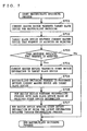
- FIG. 6 is a flowchart showing a procedure of a master/slave switching method performed by the devices according to the first embodiment of the present invention.
- FIG. 7 is a flowchart showing a detailed procedure of a master/slave switching process (step S610) of FIG. 6.
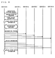
- FIG. 8 is a sequence diagram showing the procedure of FIG. 7.
- FIG. 9 is a flowchart showing another detailed procedure of the master/slave switching process (step S610) of FIG. 6.
- FIG. 10 is a sequence diagram showing the procedure of FIG. 9.
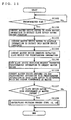
- FIG. 11 is a flowchart showing another procedure of the master/slave switching method performed by the devices according to the first embodiment of the present invention.
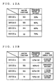
- FIGS. 12A and 12B are illustrations for describing schemes for determining a master device.
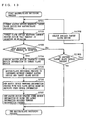
- FIG. 13 is a flowchart showing a detailed procedure performed in a master/slave switching process (step S1108) of FIG. 11.
- FIG. 14 is a flowchart showing another detailed procedure performed in the master/slave switching process (step S1108) of FIG. 11.
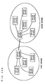
- FIGS. 15A and 15B are illustrations showing the concept of a network configured by devices performing a master/ slave switching process according to a second embodiment of the present invention.
- FIG. 16 is an illustration showing an example of a system specifically achieving the network of FIGS. 15A and 15B.
- FIG. 1 is an illustration showing the concept of a network configured by devices performing a master/slave switching process according to a first embodiment of the present invention. As shown in FIG. 1, the network according to the first embodiment is configured by one master device being connected to one or more slave devices in a wired or wireless manner for intercommunication. FIG. 1 shows an example of the network in which a
device 1 functioning as a master device managesdevices 2 through 5 functioning as slave devices. Description is made below to a mixed network of devices having a master function for functioning as a master device and a slave function for functioning as a slave device and devices having only the slave function - FIG. 2 is a block diagram illustrating the detailed structure of the
device 1, which is the master device in FIG. 1. In FIG. 2, thedevice 1 includes acommunication section 11, anetwork processing section 12, a deviceinformation processing section 13, a master/slaveswitch controlling section 14, a device's own deviceinformation managing section 15,anotherdeviceinformation managing section 16, a scheduleinformation managing section 17, and a device' sfunctional block 18. Each of thedevices 2 through 5, which are the slave devices, has the same structure as that of FIG. 2 if they have the master function. If they do not have the master function, each of thedevices 2 through 5 has a structure similar to that of FIG. 2, except that the master/slaveswitch controlling section 14 and the other deviceinformation managing section 16 are omitted. In the following description, for the sake of clear distinction of the components included in each device, components included in a device i (i = 1 to 5) are represented as a communication section i1, a network processing section i2, a device information processing section i3, a master/slave switch controlling section i4, a device's own device information managing section i5, an other device information managing section i6, a schedule information managing section i7, and a device's functional block i8. - First, each component included in the device i is schematically described.
- The communication section i1 performs a predetermined communication with a communication section(s) j1 (j is any other than i) of another device(s) j in response to instructions from the network processing section i2, the device information processing section i3 and the master/slave switch controlling section i4. The network processing section i2 performs a necessary process when its own device i or another device j newly participates in the network. The device information processing section i3 performs an information obtaining process and an information comparing and determining process based on schedule information (which will be described further below) to determine whether a master/slave switching process is to be performed. The master/slave switch controlling section i4 performs a predetermined switching process when the device information processing section i3 determines that the master/slave switching process is to be performed. The device's own device information managing section i5 stores and manages predetermined information (device's own device information) regarding the device i. The other device information managing section i6 stores and manages predetermined information (other device information) regarding the device(s) j. The schedule information managing section i7 stores and manages schedule information indicative of master device candidates by predetermined segment. The device's functional block i8 is a section that performs primary functions of the device i. For example, if the device i is a television set, the device's functional block i8 corresponds to a functional section for receiving a program and displaying the received program on a screen.
- The schedule information managed by the schedule information managing section i7 is used for narrowing down master device candidates in performing a master/slave switching process. This schedule information is useful when the environment where devices are placed is changed with time, such as when the present invention is applied to a home network. As well known, the home network is assumed to include various home electric appliances connected to one another, such as information devices (personal computers, facsimile machines, etc.), audiovisual devices (televisions, video recorders, etc.), cooking devices (microwave ovens, refrigerators, etc.), and air-conditioning devices (coolers, fan heaters, etc.). Each type of such devices has its own time zone and season when the device is frequently used. For example, it is expected that cooking devices are frequently used in the early evening for preparing dinner and so are televisions thereafter in family time, and coolers are frequently used in summer and so are fan heaters in winter. Therefore, it is preferable that a device expected to be used during a specific time zone or season should be excluded from master device candidates during that time zone or season. In order to narrow down master device candidates, schedule information as exemplarily illustrated in FIG. 3A or 3B is used. FIG. 3A depicts a schedule divided into time zones. For example, in FIG. 3A, master device candidates in a time zone of 11:00 to 14:00 are the
device 3 and thedevice 5. FIG. 3B depicts a schedule divided into seasons (dates). For example, in FIG. 3B, master device candidates from April 1 to June 20 are thedevice 2 and thedevice 3. Alternatively, the schedule information may have registered thereon devices not suitable as master devices. - FIG. 4 is an illustration showing one example of the device's own device information managed by the device's own device information managing section i5. Note that not all items included in the device's own device information are required to be stored in the device's own device information managing section i5, but it suffices that at least items that are referred to for the master/slave switching process, which will be described further below, are stored.
- In FIG. 4, the device's own device information includes items indicative of fixed performance of the device, such as its device ID, CPU power, and availability of the master function, and items indicative of variable states of the device, such as power supply type, the remaining amount of battery, and the device's condition. The device ID is identification information f or uniquely specifying the device. In Bluetooth (R), BD_Address corresponds to this device ID. The CPU power is represented by a type of the CPU and an operating clock frequency. Availability of the master function indicates whether the device has the master function (master process routine). Items other than the above included in the device's own device information are, for example, manufacturing date, standard price, rank set for each product. The power supply type indicates whether the device is powered by AC power supply or battery and, when powered by battery, indicates a type of battery (alkaline, lithium, etc). The remaining amount of battery indicates the remaining amount when the power supply type is battery. This remaining amount of battery may be represented by a ratio (%) of the remaining amount of battery to the maximum amount thereof or by an estimated remaining time for operation. When the power supply type is AC power supply, the remaining amount of battery may be set to have a maximum value or a predetermined value other than the maximum value for distinction. The device's condition includes a power-applied time, a use time, a transmission output level, a time from reception of a request to transmission of a response (a response time), information indicative of whether the device is in a power-saving mode, a CPU running ratio for measuring a load on a CPU, and the like.
- FIG. 5 is an illustration showing one example of the other device information stored by the other device information managing section i6. Note that the other device information is not restricted to the information depicted in FIG. 5, but may be freely set according to the information referred to when the master/slave switching process, which will be described further below, is performed.
- In FIG. 5, the other device information stored in the other device
information managing section 16 is related to every slave device j connected to the network, and is held only by the master device i. Every time a new device j participates in the network, the master device i obtains necessary information from the device' s own device information stored in the device's own device information managing section j5 of the new device j, and stores the obtained information in the other device information managing section i6. In the example of FIG. 1, since thedevice 1 is the master device, only the other deviceinformation managing section 16 of thedevice 1 has stored therein information regarding theother devices 2 through 5, which are the slave devices, as the other device information. Examples of items included in the other device information are, as for each device j connected to the network as a slave device, a device ID (address), an operation mode (normal/power-saving), availability of the master function, the remaining amount of battery, and quality of communication between the device i and the device(s) j (error rate, electric field strength, etc). - Next, with further reference to FIGS. 6 through 14, the master/slave switching process according to the present invention to be performed between the above-structured devices in the network shown in FIG. 1 is exemplarily described. In the present embodiment, description is made to the following two cases: one is that the master/slave switching process is performed upon participation of a new device in the network and the other is that the process is performed at other times. Furthermore, in the present embodiment, it is assumed that the master/slave switching process is performed based on the remaining amount of battery of each device.
- (1) The case where the master/slave switching process is performed upon participation of a new device in the network:
Here, the following discussion is based on the premise that themaster device 1 and theslave devices 2 through 5 have their device's own device information (FIG. 4) stored in the device's own deviceinformation managing sections 15, 25, 35, 45, and 55, respectively. Furthermore, themaster device 1 has the other device information regarding theslave devices 2 through 5 (FIG. 5) stored in the other deviceinformation managing section 16.
Adevice 6 to newly participate in the network generates a network participation request at the network processing section 62, and then transmits the generated request to the device 1 (step S601). When thedevice 1 receives the network participation request, thenetwork processing section 12 determines whether to allow participation, and then sends a response for allowing or rejecting participation to the device 6 (step S602). When allowing participation of thedevice 6, thenetwork processing section 12 stores the information received from thedevice 6 in the other device information managing section 16 (steps S603 and S604). With this, thedevice 6 participates in the network as a slave device. This new participation of thedevice 6 in the network is reported from thenetwork processing section 12 to the deviceinformation processing section 13.
Upon reception of the report, the deviceinformation processing section 13 sends a request through thecommunication section 11 to thedevice 6 for predetermined information required for determination to be made in the master/slave switching process, the predetermined information including information indicative of whether thedevice 6 has the master function (step S605). The predetermined information is resource information required for the master operation. In the present embodiment, as the predetermined information, availability of the master function and the remaining amount of battery are requested. However, the predetermined information to be requested can be freely designed depending on the performance and the objective of the system to be configured, and the like. Also, this request for the predetermined information can be sent at one time or a plurality of times. When the request is sent at a plurality of times, its response can be sent at one time or a plurality of times.
When thedevice 6 receives the request for the predetermined information from thedevice 1, the device information processing section 63 extracts information regarding availability of the master function and the current remaining amount of battery from the device's own device information managing section 65, and then sends the extracted information to the device 1 (step S606).
When thedevice 1 receives the predetermined information from thedevice 6, the deviceinformation processing section 13 stores the predetermined information, that is, availability of the master function and the remaining amount of battery, in the other deviceinformation managing section 16. Next, the deviceinformation processing section 13 determines whether thedevice 6 is to be subjected to the master/slave switching process (step S607). In this step S607, it is determined that thedevice 6 is to be subjected to the master/slave switching process when it is known based on the other device information and the schedule information that thedevice 6 has the master function and is a master device candidate. When determining that thedevice 6 is to be subjected to the switching process, the deviceinformation processing section 13 reports as such to the master/slaveswitch controlling section 14. Upon reception of the report, the master/slaveswitch controlling section 14 extracts the information regarding the remaining amount of battery of thedevice 6 from the other deviceinformation managing section 16 and the information regarding the remaining amount of battery of thedevice 1 from the device's own deviceinformation managing section 15. The master/slaveswitch controlling section 14 then compares both pieces of information to determine whether thedevice 6 is more suitable as the master device than thedevice 1, that is, whether the performance of thedevice 6 is higher as the master device than that of the device 1 (steps S608 and S609). Specifically, the device whose ratio of the remaining amount of battery is larger or whose estimated remaining time for operation is longer is determined as the device more suitable as the master device.
When information other than the remaining amount of battery is used for determination, the following scheme can be taken. When the power supply type is used, a priority order is set in advance, such as "AC power supply> lithium battery > nickel cadmium battery > alkaline battery> manganese battery". Based on the priority order, which of thedevices
Upon determination that thedevice 6 is more suitable (has a higher performance) as the master device, the master/slaveswitch controlling section 14 of thedevice 1 performs, in cooperation with the master/slave switch controlling section 64 of thedevice 6, a master/slave switching process for causing thedevice 6 to perform a master operation (step S610). This master/slave switching process is performed in the following two ways (refer to FIGS. 7 through 10).- a. First master/slave switching process (FIGS. 7 and 8)
Thedevice 1 transmits a master/slave switching request to thedevice 6, which is subjected to the master/slave switching process (step S701). Upon reception of the master/slave switching request, thedevice 6 transmits a response indicating that the request is accepted or rejected to the device 1 (step S702). The request is rejected in cases such as where thedevice 6 is once connected to the network but this connection is merely temporary and disconnection is scheduled shortly thereafter or where it is difficult to perform a master operation in view of the CPU power (for example, thedevice 6 is currently playing back moving pictures, and therefore taking on other tasks are not desired).
Upon reception of the response indicating that the request is accepted, thedevice 1 transmits the other device information stored in the other deviceinformation managing section 16 to the device 6 (steps S703 and S704). Thedevice 6 then stores the other device information received from thedevice 1 in the other device information managing section 66 and performs a master/slave switching process with the device 1 (step S705). With this, thedevice 6, which has been a slave device, becomes the master device, while thedevice 1, which has been the master device, becomes a slave device.
Thedevice 6 then performs a reconnecting process on theslave devices 2 through 5 based on the other device information stored in the other device information managing section 66, and reports to them that thedevice 6 has become a new master device (step S706). Simultaneously with this process, thedevice 6 obtains the latest other device information from each of thedevices 1 through 5 to update the other device information stored in the other device information managing section 66 (step S707). The connection that has been established between thedevice 1 and thedevices 2 through 5 may be cut out when thedevice 1 transmits the other device information to thedevice 6 or when thedevice 6 performs a reconnecting process on thedevices 2 through 5. - b. Second master/slave switching process (FIGS. 9 and 10)
Thedevice 1 transmits a master/slave switching request to the device 6 (step S901). Upon reception of the master/slave switching request, thedevice 6 transmits a response indicating that the request is accepted or rejected to the device 1 (step S902). The cases where the request is rejected have been described above.
Upon reception of the response indicating the request is accepted, thedevice 1 transmits the device ID (address) of thedevice 6, which will become a new master device, to each of thedevices 2 through 5 based on the other device information stored in the other device information managing section 16 (steps S903 and S904). Thedevice 6 then performs a master/slave switching process with the device 1 (step S905). With this, thedevice 6, which has been a slave device, becomes the master device, while thedevice 1, which has been the master device, becomes a slave device.
Thedevices 2 through 5 then use their device IDs to perform a reconnecting process on the device 6 (step S906). Simultaneously with this process, thedevice 6 obtains the latest other device information from each of thedevices 1 through 5, and stores the obtained information in the other device information managing section 66 (step S907). Alternatively, the other device information may be sent in advance from thedevice 1 to thedevice 6 for update at the time of the reconnecting process. Still alternatively, the other device information may be newly generated at the time of the reconnecting process. Also, the connection that has been established between thedevice 1 and thedevices 2 through 5 may be cut out when thedevice 1 performs a master/slave switching process with thedevice 6 or when thedevices 2 through 5 performs a reconnecting process on thedevice 6.
- a. First master/slave switching process (FIGS. 7 and 8)
- (2) The case where the master/slave switching process is performed at a predetermined time:
- Here, the following discussion is based on the premise that the
master device 1 and theslave devices 2 through 5 have the device's own device information (FIG. 4) stored in the device's own deviceinformation managing section 15, 25, 35, 45, and 55, respectively. Furthermore, themaster device 1 has the other device information regarding theslave devices 2 through 5 (FIG. 5) stored in the other deviceinformation managing section 16. - The device
information processing section 13 of thedevice 1 determines whether a predetermined time has come (step S1101). The predetermined time may be a predetermined time of day, a predetermined time interval, a time when the state of the device is changed, such as a time when a command is issued, a time when the remaining amount of battery is changed or a time when the communication quality is deteriorated, or a time when the processing load of the CPU is changed. The change of the remaining amount of battery can be easily detected by, for example, determining whether the remaining amount of battery is lower than a predetermined threshold. The degradation in communication quality can be easily detected by, for example, determining whether an error rate (frequency of occurrence of a retransmitting process) as to data received from each slave device has been increased or determining whether the electric field intensity has been attenuated. Examples of the time when a master/slave switching process unique to a home network is required are a time when a master video device starts preprogrammed recording and a time when a master facsimile machine starts receiving facsimile. - When it is determined that the predetermined time has come, the device
information processing section 13 refers to the other device information stored in the other deviceinformation managing section 16 to extract devices having the master function (step S1102). The deviceinformation processing section 13 then refer to the schedule information managed by the scheduleinformation managing section 17 to further extract only master device candidates from the devices extracted in step S1102 (step S1103). The deviceinformation processing section 13 then transmits, to the extracted master device candidates, a request for the predetermined information required for determining whether to perform the master/slave switching process (in the present embodiment, a request for the remaining amount of battery) (step S1104). - The device information processing section i3 of each device i receiving the request for the remaining amount of battery extracts the information about the current remaining amount of battery from the device's own information managing section i5, and then transmits the extracted information to the device 1 (step S1105).
- When the
device 1 receives the remaining amount of battery from each device i, the deviceinformation processing section 13 stores the received remaining amount of battery in the other deviceinformation managing section 16, and also reports the received remaining amount of battery to the master/slaveswitch controlling section 14. Upon reception of this report, the master/slaveswitch controlling section 14 extracts the information about the remaining amount of battery of each device i from the other deviceinformation managing section 16 and the information about the remaining amount of battery of thedevice 1 from the device's own deviceinformation managing section 15. The master /slaveswitch controlling section 14 then compares all pieces of extracted information to determine whether a device that is more suitable as the master device than thedevice 1 is present, that is, whether a device whose performance as the master device is higher than that of thedevice 1 is present (step S1106). Specifically, the device whose ratio of the remaining amount is the largest or whose estimated remaining time for operation is the longest is determined as the device most suitable as the master device. - For example, when the remaining amounts of battery of the
devices 1 through 5 are as shown in FIG. 12A, thedevice 2 is determined as the device most suitable as the master device. At this time, if the above-mentioned power supply type is taken into consideration, a predetermined coefficient is set for each power supply type according to the priority order. Then, by adding the predetermined coefficient to the remaining amount of battery or by multiplying the remaining amount of battery by the predetermined coefficient, the device most suitable as the master device is determined (FIG. 12B). In this case, thedevice 3 is determined as the device most suitable as the master device. Determination to be made by using information other than the remaining amount of battery has been described above. - Upon determination that a device that is more suitable (has a higher performance) as the master device than the
device 1 is present, the master/slaveswitch controlling section 14 of thedevice 1 performs, in cooperation with the master/slave switch controlling section of the more suitable device, a master/slave switching process for causing the more suitable device to perform a master operation (steps S1107 and S1108). This master/slave switching process in step S1108 is performed basically in the above-described two ways (refer to FIGS. 7 through 10). However, the master/slave switching process in step S1108 is different from that shown in FIGS. 7 through 10 in the following point. That is, as shown in FIGS. 13 and 14, assuming that there are a plurality of master device candidates, when a first one of them rejects the master/slave switching request, the next one is subjected to a predetermined process. A routine of such a predetermined process is shown in steps S1301 and S1302 of FIG. 13 and steps S1401 and S1402 of FIG. 14. Hereinafter, this different point is additionally described. - Upon receiving the response rejecting the request, the
device 1 determines whether another slave device suitable as the master device is present (steps S1301 and S1401). If such a slave device is present, thedevice 1 again performs a master/slave switching process on this slave device (steps S1302 and S1402). - As described above, according to the device performing the master/slave switching process of the first embodiment of the present invention, the device functioning as the master device is dynamically changed among the devices forming the network. With this, even if an inconvenience, such as battery exhaustion, occurs to the current master device, the current master device is switched to a new master device for maintaining the network. Also, even if the environment of the devices changes with time, it is possible to narrow down the most suitable master device candidate with the use of the schedule information. This reduces the load on the system caused by the master/slave switching process.
- FIG. 15A is an illustration showing the concept of a network configured by devices performing a master/slave switching process according to a second embodiment of the present invention. As shown in FIG. 15A, the network according to the second embodiment has the structure in which a first network and a second network, each of which includes one master device and one or more slave deices as described in the first embodiment, are connected to each other at their master devices. For example, in the wireless communication technology, such as Bluetooth (R), the first network and the second network correspond to Piconets, while the network according to the second embodiment that includes these two networks corresponds to a Scatternet. A feature of the second embodiment is that the master/slave switching process is performed between the first network and the second network. In the network according to the second embodiment, the master devices of the first and second networks each perform the master function and the slave function simultaneously. This is because, when viewed from the master device of the first network, the master device of the second network is one of the slave devices and, when viewed from the master device of the second network, the master device of the first network is one of the slave devices.
- In the state shown in FIG. 15A, when the device state is changed, such as when the communication quality is deteriorated, the master/slave switching process is performed on the relation between the master devices of the first and second networks. In this process, either one or both of the error rate and the electric field intensity are checked for all combinations of the devices included in the first and second networks. Here, if the schedule information is used together, the number of combinations of the devices can be reduced, thereby reducing the processing load on the system. Of these combinations, one combination of devices that is most suitable is then selected. On the selected devices, the master/slave switching process is then performed in each of the first and second networks. Finally, a new master device in the first network after switching and a new master device in the second network after switching are connected to each other. With this, as shown in FIG. 15B, for example, a pair of devices, one in the first network and the other in the second network, can be determined as the master devices.
- As has been described in the foregoing, according to the device for performing the master/slave switching process of the second embodiment of the present invention, even when a plurality of small networks are combined to form one large network, the effect of the first embodiment can be obtained. A specific example is shown in FIG. 16, in which a plurality of security sensors (devices) for preventing crime form a several number of small networks, and these small networks further form a large network.
- In the device that performs the master/slave switching process of the present invention, each of the functional blocks of the device
information processing section 13, the master/slaveswitch controlling section 14, the device's own deviceinformation managing section 15, the other deviceinformation managing section 16, and the scheduleinformation managing section 17 are typically achieved by a large-scale integrated (LSI) circuit (called an IC, a system LSI, a super LSI, a ultra LSI, or the like, depending on the degree of integration) (refer to FIG. 2). Each of the blocks may be formed on one chip, or all or part of the blocks may be formed on one chip. - Also, circuit integration is achieved not only by an LSI but also by a dedicated circuit or a general-purpose processor. Further, a Field Programmable Gate Array (FPGA), which is programmable after manufacturing the LSI, or a reconfigurable processor capable of reconfiguring the connection of circuit cells and the setting inside the LSI can be used.
- Furthermore, integration of the functional blocks can be performed by using a new circuit integration technology that would replace the LSI technology with the advance of the semiconductor technology or with the advent of another derivative technology. One possible technology that would be adapted for use is a biotechnological technique.
- Furthermore, the method of performing the master/slave switching process of the present invention is achieved by a CPU interpreting predetermined program data that is stored in a storage device (a ROM; a RAM, a hard disk, etc.) and is capable of causing the above-described processes to be performed. In this case, the program data may be introduced through a recording medium to the storage device, or may be executed directly from the recording medium.
- The present invention can be used for a network system in which a master device manages slave devices, for example, and is particularly suitable when a device most suitable as the master device in the network system is dynamically changed in consideration of the performance and state of each device.
Claims (10)
- A device having a master function for use in a network system in which a master device (1) manages at least one slave device (2, 3, 4, 5), the device comprising:a device's own device information managing section (15) operable to manage device's own device information, which includes at least predetermined information, regarding a state change of the device;an other device information managing section (16) operable to manage other device information regarding at least one another device connected to the network system, the other device information including at least availability of the master function;a schedule information managing section (17) operable to manage schedule information indicative of master device candidates by a plurality of segments of at least time of day or season;a device information processing section (13) operable, when the device operates as the master device, to specify, at a predetermined time, a slave device (2, 3, 4, 5) from among a plurality of slave devices (2, 3, 4, 5) which are the master device candidates indicated by the schedule information in a segment of time of day or season corresponding to the predetermined time based on the other device information, and operable to obtain predetermined information regarding a state change of the specified slave device (2, 3, 4, 5) from the specified slave device (2, 3, 4, 5) ; anda switch controlling section (14) operable to compare the predetermined information regarding the state change of the specified slave device (2, 3, 4, 5) obtained by the device information processing section with the predetermined information regarding the state change of the device included in the device's own device information, and operable, when the state change of the specified slave device (2, 3, 4, 5) is smaller than the state change of the device, to switch between a master operation operated by the device and a slave operation operated by the specified slave device (2, 3, 4, 5).
- The device according to claim 1, wherein
the master device candidates indicated by the schedule information in a segment of time of day is at least one device other than a device which is likely to be frequently used in the segment of time of day. - The device according to claim 1, wherein
the master device candidates indicated by the schedule information in a segment of season is at least one device other than a device which is likely to be frequently used in the segment of season. - The device according to claim 1, wherein
the switch controlling section transmits the other device information managed by the other device information managing section to the specified slave device (2, 3, 4, 5). - The device according to claim 1, wherein
the predetermined time is a time when a change occurs to the device's own device information managed by the device's own device information managing section (15). - The device according to claim 5, wherein
the change of the device's own device information is a reduction in a remaining amount of battery. - The device according to claim 5, wherein
the change of the device's own device information is a deterioration in communication quality. - A master/slave switching method to be performed on a device currently performing a slave operation by a device currently performing a master operation, the method comprising the steps of:managing a schedule information indicative of master device candidates by a plurality of segments of at least time of day or season;specifying, at a predetermined time, a slave device (2, 3, 4, 5) from among a plurality of slave devices (2, 3, 4, 5) which are master device candidates indicated by schedule information in a segment of at least time of day or season corresponding to the predetermined time based on the other device information including at least availability of the master function of other devices connected to a network;obtaining predetermined information regarding a state change of the specified device from the specified slave device (2, 3, 4, 5); andcomparing (S608) the predetermined information regarding the state change of the specified slave device (2, 3, 4, 5) obtained in the information obtaining step with predetermined information regarding the state change of the device of device's own device information of the device currently performing the master operation; andswitching (S610), when the state change of the specified slave device (2, 3, 4, 5) is smaller than the state change of the device, between a master operation operated by the device and a slave operation operated by the specified slave device (2, 3, 4, 5).
- A computer-readable program for causing a device currently performing a master operation to perform a method of performing a master/slave switching process on a device currently performing a slave operation, the program comprising the steps of:managing a schedule information indicative of master device candidates by a plurality of segments of at least time of day or season;specifying, at a predetermined time, a slave device (2, 3, 4, 5) from among a plurality of slave devices (2, 3, 4, 5) which are master device candidates indicated by schedule information in a segment of at least time of day or season corresponding to the predetermined time based on the other device information including at least availability of the master function of other devices connected to a network;obtaining predetermined information regarding a state change of the specified device from the specified slave device (2, 3, 4, 5); andcomparing (S608) the predetermined information regarding the state change of the specified slave device (2, 3, 4, 5) obtained in the information obtaining step with predetermined information regarding the state change of the device of device's own device information of the device currently performing the master operation; andswitching (S610), when the state change of the specified slave device (2, 3, 4, 5) is smaller than the state change of the device, between a master operation operated by the device and a slave operation operated by the specified slave device (2, 3, 4, 5).
- An integrated circuit for use in a device having a master function, the device being used in a network system in which a master device manages at least one slave device (2, 3, 4, 5), the circuit comprising:a device's own device information managing section (15) operable to manage device's own device information, which includes at least predetermined information, regarding a state change of a device including the circuit;an other device information managing section (16) operable to manage other device information regarding at least one another device connected to the network system, the other device information including at least availability of the master function;a schedule information managing section (17) operable to manage schedule information indicative of master device candidates by a plurality of segments of at least time of day or season;a device information processing section (13) operable, when the device operates as the master device, to specify, at a predetermined time, a slave device (2, 3, 4, 5) from among a plurality of slave devices (2, 3, 4, 5) which are the master device candidates indicated by the schedule information in a segment of time of day or season corresponding to the predetermined time based on the other device information, and operable to obtain predetermined information regarding a state change of the specified slave device (2, 3, 4, 5) from the specified slave device (2, 3, 4, 5); anda switch controlling section (14) operable to compare the predetermined information regarding the state change of the specified slave device (2, 3, 4, 5) obtained by the device information processing section with the predetermined information regarding the state change of the device included in the device's own device information, and operable, when the state change of the specified slave device (2, 3, 4, 5) is smaller than the state change of the device, to switch between a master operation operated by the device and a slave operation operated by the specified slave device (2, 3, 4, 5).
Applications Claiming Priority (2)
| Application Number | Priority Date | Filing Date | Title |
|---|---|---|---|
| JP2003156684 | 2003-06-02 | ||
| PCT/JP2004/007859 WO2004109996A1 (en) | 2003-06-02 | 2004-05-31 | Device, method, and program for performing master/slave switching process |
Publications (2)
| Publication Number | Publication Date |
|---|---|
| EP1629643A1 EP1629643A1 (en) | 2006-03-01 |
| EP1629643B1 true EP1629643B1 (en) | 2008-02-06 |
Family
ID=33508326
Family Applications (1)
| Application Number | Title | Priority Date | Filing Date |
|---|---|---|---|
| EP04745622A Expired - Lifetime EP1629643B1 (en) | 2003-06-02 | 2004-05-31 | Device, method, and program for performing master/slave switching process |
Country Status (7)
| Country | Link |
|---|---|
| US (1) | US20050262216A1 (en) |
| EP (1) | EP1629643B1 (en) |
| JP (1) | JP4393510B2 (en) |
| KR (1) | KR20060017576A (en) |
| CN (1) | CN1701570A (en) |
| DE (1) | DE602004011665T2 (en) |
| WO (1) | WO2004109996A1 (en) |
Families Citing this family (98)
| Publication number | Priority date | Publication date | Assignee | Title |
|---|---|---|---|---|
| JP4274050B2 (en) * | 2004-06-03 | 2009-06-03 | ソニー株式会社 | Information processing apparatus and method, recording medium, and program |
| US20060190549A1 (en) * | 2004-07-23 | 2006-08-24 | Kouichi Teramae | Multi-media information device network system |
| US7881757B2 (en) | 2004-12-21 | 2011-02-01 | Panasonic Corporation | Power management method of wireless nodes |
| JP4239987B2 (en) * | 2005-02-24 | 2009-03-18 | ブラザー工業株式会社 | Network systems, devices, and programs |
| US20060215673A1 (en) * | 2005-03-11 | 2006-09-28 | Interdigital Technology Corporation | Mesh network configured to autonomously commission a network and manage the network topology |
| US7624290B2 (en) * | 2005-03-22 | 2009-11-24 | Sony Corporation | Power-save control for network master device |
| JP4587384B2 (en) * | 2005-06-08 | 2010-11-24 | シャープ株式会社 | Data communication system and data communication apparatus |
| KR100696111B1 (en) * | 2005-07-15 | 2007-03-20 | 삼성전자주식회사 | Communication system |
| US7756942B2 (en) * | 2005-07-21 | 2010-07-13 | Sony Corporation | System and method for establishing master component in multiple home networks |
| CN100386734C (en) * | 2005-10-28 | 2008-05-07 | 北京和利时系统工程股份有限公司 | Dual-machine data acquisition master-slave switching method and device with multiple redundant modes coexisting |
| JP4906315B2 (en) * | 2005-10-31 | 2012-03-28 | キヤノン株式会社 | COMMUNICATION CONTROL DEVICE, COMPUTER CONTROL METHOD, AND CONTROL PROGRAM |
| US9215748B2 (en) | 2005-11-28 | 2015-12-15 | Canon Kabushiki Kaisha | Communication apparatus, control method for communication apparatus, and communication system |
| JP4829600B2 (en) * | 2005-11-28 | 2011-12-07 | キヤノン株式会社 | COMMUNICATION DEVICE AND COMMUNICATION DEVICE CONTROL METHOD |
| KR100693537B1 (en) * | 2006-03-17 | 2007-03-14 | 주식회사 팬택앤큐리텔 | Method and apparatus for sending and receiving messages with Bluetooth mobile communication terminal |
| JP4189469B2 (en) * | 2006-05-25 | 2008-12-03 | コニカミノルタビジネステクノロジーズ株式会社 | Information processing apparatus, information processing system, and information processing method |
| US7856002B2 (en) | 2006-09-11 | 2010-12-21 | Samsung Electronic Co., Ltd. | System and method for wireless communication having a device coordinator selection capability |
| US8312098B2 (en) * | 2006-11-09 | 2012-11-13 | Abbott Medical Optics Inc. | Serial communications protocol for safety critical systems |
| US7730362B2 (en) * | 2006-11-09 | 2010-06-01 | Abbott Medical Optics Inc. | Serial communications protocol |
| US8401001B2 (en) | 2007-03-28 | 2013-03-19 | Intel Corporation | Method and apparatus of connectivity recovery in wireless network |
| WO2009031320A1 (en) * | 2007-09-07 | 2009-03-12 | Panasonic Corporation | Wireless communication device and transmission method |
| US8468374B2 (en) * | 2008-07-11 | 2013-06-18 | Marvell World Trade Ltd. | Access point rotation for sharing power load |
| JP5564774B2 (en) * | 2008-09-24 | 2014-08-06 | ソニー株式会社 | Information processing apparatus and method, and program |
| JP5213672B2 (en) * | 2008-12-05 | 2013-06-19 | 能美防災株式会社 | Alarm system and alarm |
| JP5264453B2 (en) * | 2008-12-05 | 2013-08-14 | 能美防災株式会社 | Alarm |
| MX2011010025A (en) | 2009-03-24 | 2012-01-12 | Volvo Group North America Llc | Support for vertically mounted exhaust components. |
| JP5705415B2 (en) | 2009-04-06 | 2015-04-22 | ソニー株式会社 | Wireless communication apparatus, communication system, communication method, and program |
| JP5434230B2 (en) * | 2009-04-22 | 2014-03-05 | ソニー株式会社 | Wireless communication apparatus, wireless communication system, wireless communication method, and program |
| US8769108B2 (en) * | 2009-06-24 | 2014-07-01 | Intel Corporation | Peer-to-peer negotiation in a wireless network |
| US9084276B2 (en) * | 2009-09-11 | 2015-07-14 | Aerovironment, Inc. | Dynamic transmission control for a wireless network |
| US10836483B2 (en) | 2009-09-11 | 2020-11-17 | Aerovironment, Inc. | Ad hoc dynamic data link repeater |
| JP4823345B2 (en) * | 2009-09-18 | 2011-11-24 | 三菱重工業株式会社 | Battery system |
| JP5294416B2 (en) * | 2009-09-25 | 2013-09-18 | Kddi株式会社 | Remote control system and remote control method |
| JP5371047B2 (en) * | 2009-09-29 | 2013-12-18 | Kddi株式会社 | Method for autonomously determining a device for executing a predetermined function in a network, communication device and program for the method |
| KR101598886B1 (en) | 2009-10-13 | 2016-03-03 | 삼성전자주식회사 | Apparatus and method for connecting peer to peer using wlan in a mobile communication terminal |
| US9008581B2 (en) * | 2009-11-08 | 2015-04-14 | Intel Mobile Communications GmbH | Radio devices and methods for controlling radio devices |
| CN103210383A (en) * | 2010-09-30 | 2013-07-17 | 苹果公司 | Wireless accessory device pairing transfer between multiple host devices |
| KR101742985B1 (en) * | 2010-11-02 | 2017-06-02 | 엘지전자 주식회사 | The method of determining group owner in peer to peer network and the device thereof |
| JP2012109677A (en) * | 2010-11-15 | 2012-06-07 | I-O Data Device Inc | Communication device and recorder |
| US9270784B2 (en) * | 2011-02-16 | 2016-02-23 | Masque Publishing, Inc. | Peer-to-peer communications |
| US8838722B2 (en) | 2011-02-16 | 2014-09-16 | Masque Publishing, Inc. | Communications adaptable to mobile devices |
| JP5664390B2 (en) | 2011-03-23 | 2015-02-04 | ソニー株式会社 | Wireless communication apparatus, wireless communication method, program, and wireless communication system |
| JP5834568B2 (en) * | 2011-07-19 | 2015-12-24 | ソニー株式会社 | Information processing apparatus, information processing method, and computer program |
| JP5821390B2 (en) | 2011-08-10 | 2015-11-24 | 株式会社リコー | Wireless communication apparatus, wireless communication program, and wireless communication method |
| WO2013042630A1 (en) * | 2011-09-22 | 2013-03-28 | Necカシオモバイルコミュニケーションズ株式会社 | Communication system, portable terminal device, method for managing communication system, and program |
| CN102572721B (en) * | 2012-01-13 | 2014-08-13 | 中兴通讯股份有限公司 | Mobility management method, system and equipment for group terminals |
| JP5969775B2 (en) * | 2012-03-05 | 2016-08-17 | キヤノン株式会社 | Information processing apparatus, control method, and program |
| JP6080095B2 (en) * | 2012-07-30 | 2017-02-15 | カシオ計算機株式会社 | Wireless communication system and program |
| US9430090B2 (en) * | 2012-08-08 | 2016-08-30 | Uni-Structures, Inc. | Switch system for outputting multimedia content to a digital sign |
| US9508310B2 (en) * | 2012-08-08 | 2016-11-29 | Michael S. Barnes | Manual switch system for outputting multimedia content to a digital sign |
| JP5651662B2 (en) * | 2012-09-12 | 2015-01-14 | 株式会社東芝 | Wireless communication device |
| CN103813325B (en) * | 2012-11-07 | 2017-06-06 | 株式会社理光 | The network management of limited area self-organizing network, communication equipment and system |
| JP6347633B2 (en) * | 2013-06-14 | 2018-06-27 | キヤノン株式会社 | COMMUNICATION DEVICE, COMMUNICATION METHOD, AND PROGRAM |
| TWI506912B (en) * | 2013-08-02 | 2015-11-01 | Simplo Technology Co Ltd | System of wireless power transmission and method thereof |
| JP5858966B2 (en) * | 2013-09-24 | 2016-02-10 | キヤノン株式会社 | Communication device for executing communication parameter setting procedure, communication device control method, and program |
| CN103533588A (en) * | 2013-09-27 | 2014-01-22 | 宇龙计算机通信科技(深圳)有限公司 | Method for switching current operation application in sub machine to host machine for operation, and mobile terminal for method |
| US9078072B2 (en) * | 2013-10-07 | 2015-07-07 | Bose Corporation | Audio distribution |
| JP2015079291A (en) * | 2013-10-15 | 2015-04-23 | 富士ゼロックス株式会社 | Information processing device, information processing system and program |
| JP2014078981A (en) * | 2013-12-05 | 2014-05-01 | Sony Corp | Wireless communication device, wireless communication system, wireless communication method, and program |
| JP6109771B2 (en) | 2014-03-13 | 2017-04-05 | 株式会社東芝 | File transmission / reception device and file transmission / reception method |
| JP5708862B2 (en) * | 2014-04-14 | 2015-04-30 | ソニー株式会社 | Information processing apparatus and method, and program |
| US9875644B2 (en) | 2014-09-09 | 2018-01-23 | Tyco Fire & Security Gmbh | Master slave wireless fire alarm and mass notification system |
| WO2016104847A1 (en) * | 2014-12-26 | 2016-06-30 | 두산중공업 주식회사 | Wireless lan d2d duplexing terminal and method |
| CN104572193A (en) * | 2014-12-29 | 2015-04-29 | 联想(北京)有限公司 | Control method among multiple apparatuses and electronic apparatus thereof |
| CN105989717B (en) * | 2015-02-15 | 2018-07-31 | 北京东土科技股份有限公司 | A kind of distributed redundancy control method and system of intelligent transportation |
| CN104811895B (en) * | 2015-04-01 | 2018-04-20 | 石姗姗 | Connection method and device of low-power-consumption Bluetooth |
| JP5994893B2 (en) * | 2015-04-17 | 2016-09-21 | ソニー株式会社 | Wireless communication apparatus, wireless communication system, wireless communication method, and program |
| US10075836B2 (en) * | 2015-06-23 | 2018-09-11 | Intel Corporation | Group management of devices methods, apparatuses and systems |
| JP6314920B2 (en) * | 2015-06-25 | 2018-04-25 | 京セラドキュメントソリューションズ株式会社 | Image forming apparatus |
| US10644940B2 (en) * | 2015-07-08 | 2020-05-05 | Convida Wireless, Llc | M2M clustering management |
| WO2017015310A2 (en) | 2015-07-20 | 2017-01-26 | Aerovironment, Inc. | Ad hoc dynamic data link repeater |
| JP2016001919A (en) * | 2015-08-26 | 2016-01-07 | ソニー株式会社 | Wireless communication device |
| CN105224494A (en) * | 2015-10-28 | 2016-01-06 | 小米科技有限责任公司 | Method for handover control and device |
| CN105337822B (en) * | 2015-11-04 | 2019-04-16 | Oppo广东移动通信有限公司 | A kind of selection method and relevant device of main playback equipment |
| JP2016028354A (en) * | 2015-11-05 | 2016-02-25 | ソニー株式会社 | Information processing device, information processing method and computer program |
| WO2017113924A1 (en) * | 2015-12-31 | 2017-07-06 | Lam Cho Wing | System including alternation of sensor connection and transmission mechanism for motion sensing garment |
| JP6754127B2 (en) * | 2016-05-18 | 2020-09-09 | 国立研究開発法人情報通信研究機構 | Power saving communication system |
| JP6222314B2 (en) * | 2016-08-25 | 2017-11-01 | ソニー株式会社 | Wireless communication device |
| JP6918565B2 (en) * | 2017-05-02 | 2021-08-11 | 株式会社メガチップス | Communication terminal devices, information communication systems, programs and information communication methods |
| US10585706B2 (en) * | 2017-06-12 | 2020-03-10 | Dell Products, L.P. | System and method for allocating memory devices among information handling systems in a chassis |
| JP2018007270A (en) * | 2017-09-19 | 2018-01-11 | Kddi株式会社 | Terminal device, position acquisition method and program |
| CN107797461A (en) * | 2017-09-30 | 2018-03-13 | 广东美的制冷设备有限公司 | Progress control method, resource shared device and computer-readable recording medium |
| CN107807965B (en) * | 2017-09-30 | 2020-09-01 | 广东美的制冷设备有限公司 | Operation control method, resource sharing device, and computer-readable storage medium |
| US10742338B2 (en) * | 2018-01-26 | 2020-08-11 | Clip Interactive, Llc | Seamless integration of radio broadcast audio with streaming audio |
| JP6741720B2 (en) * | 2018-04-20 | 2020-08-19 | ソフトバンク株式会社 | Battery remaining amount estimation system, battery remaining amount estimation method, battery remaining amount estimation program, calculation system, calculation method, and calculation program |
| CN108848469B (en) * | 2018-09-21 | 2021-12-24 | 英华达(上海)科技有限公司 | Group establishing method, group establishing system, switching device, electronic equipment and storage medium |
| CN109542205B (en) * | 2018-11-15 | 2023-11-10 | Oppo广东移动通信有限公司 | Electronic equipment, data processing methods and storage media |
| DE102019206195A1 (en) * | 2019-04-30 | 2020-11-05 | Volkswagen Aktiengesellschaft | Method for configuring networked control units in a network and control unit arrangement |
| US12236275B2 (en) | 2019-08-20 | 2025-02-25 | Nokia Solutions And Networks Oy | Master slave processing acquisition and rotation |
| CN112954819B (en) * | 2019-12-11 | 2023-09-22 | 华为技术有限公司 | Device networking method, electronic device and system |
| JP7347272B2 (en) * | 2020-03-11 | 2023-09-20 | 株式会社デンソー | electrical equipment |
| WO2021226805A1 (en) * | 2020-05-11 | 2021-11-18 | Oppo广东移动通信有限公司 | Switching method and apparatus, and cloud platform and device |
| CN112399127B (en) * | 2020-10-29 | 2024-05-14 | 维沃移动通信有限公司 | Video communication control method and device and electronic equipment |
| JP7567573B2 (en) * | 2021-03-10 | 2024-10-16 | 株式会社富士通ゼネラル | Air conditioner and air conditioning system |
| JP7735722B2 (en) * | 2021-08-30 | 2025-09-09 | 株式会社デンソー | surveillance system |
| JP7711497B2 (en) * | 2021-08-30 | 2025-07-23 | 株式会社デンソー | Surveillance system |
| JP7711496B2 (en) * | 2021-08-30 | 2025-07-23 | 株式会社デンソー | Surveillance system |
| JP7710413B2 (en) | 2022-05-20 | 2025-07-18 | 株式会社メガチップス | COMMUNICATION TERMINAL DEVICE, INFORMATION COMMUNICATION SYSTEM, PROGRAM, AND INFORMATION COMMUNICATION METHOD |
| KR20250098532A (en) * | 2023-12-22 | 2025-07-01 | 주식회사 엘지에너지솔루션 | Battery unit and battery system comprising thereof |
Family Cites Families (15)
| Publication number | Priority date | Publication date | Assignee | Title |
|---|---|---|---|---|
| EP0752666A3 (en) * | 1995-07-06 | 2004-04-28 | Sun Microsystems, Inc. | Method and apparatus for fast-forwarding slave requests in a packet-switched computer system |
| US6199133B1 (en) * | 1996-03-29 | 2001-03-06 | Compaq Computer Corporation | Management communication bus for networking devices |
| US6005759A (en) * | 1998-03-16 | 1999-12-21 | Abb Power T&D Company Inc. | Method and system for monitoring and controlling an electrical distribution network |
| JP2000057217A (en) * | 1998-08-10 | 2000-02-25 | Ibm Japan Ltd | Schedule display method, schedule change method, schedule management system, schedule management device, storage medium storing schedule management program |
| US6222530B1 (en) * | 1998-08-21 | 2001-04-24 | Corporate Media Partners | System and method for a master scheduler |
| DE19930423A1 (en) * | 1999-07-01 | 2001-01-18 | Siemens Ag | Cordless data transmission network and method for its administration |
| JP2001103570A (en) * | 1999-09-30 | 2001-04-13 | Toshiba Corp | Communication system, communication device and communication method used in this communication system |
| US6658579B1 (en) * | 2000-05-20 | 2003-12-02 | Equipe Communications Corporation | Network device with local timing systems for automatic selection between redundant, synchronous central timing systems |
| KR100620289B1 (en) * | 2000-07-25 | 2006-09-07 | 삼성전자주식회사 | How to operate a private simple network when leaving the master |
| US7035275B2 (en) * | 2001-01-16 | 2006-04-25 | Texas Instruments Incorporated | Non-collaborative mechanisms for enhanced coexistence of wireless networks |
| EP1324540B1 (en) * | 2001-12-28 | 2011-08-17 | Fujitsu Toshiba Mobile Communications Limited | Radio communication device |
| JP3833145B2 (en) * | 2002-06-11 | 2006-10-11 | Tdk株式会社 | Multilayer feedthrough capacitor |
| US7277417B2 (en) * | 2003-04-29 | 2007-10-02 | Broadcom Corporation | Low power protocol for wireless terminal peer-to-peer communications |
| US7668923B2 (en) * | 2003-10-14 | 2010-02-23 | International Business Machines Corporation | Master-slave adapter |
| JP2005277655A (en) * | 2004-03-24 | 2005-10-06 | Sony Corp | Input / output terminal, master device, slave device, information processing system and method, and program for input / output terminal, master device and slave device |
-
2004
- 2004-05-31 CN CNA200480000733XA patent/CN1701570A/en active Pending
- 2004-05-31 KR KR20057002829A patent/KR20060017576A/en not_active Withdrawn
- 2004-05-31 JP JP2006508496A patent/JP4393510B2/en not_active Expired - Fee Related
- 2004-05-31 DE DE602004011665T patent/DE602004011665T2/en not_active Expired - Lifetime
- 2004-05-31 WO PCT/JP2004/007859 patent/WO2004109996A1/en not_active Ceased
- 2004-05-31 US US10/522,249 patent/US20050262216A1/en not_active Abandoned
- 2004-05-31 EP EP04745622A patent/EP1629643B1/en not_active Expired - Lifetime
Also Published As
| Publication number | Publication date |
|---|---|
| WO2004109996A1 (en) | 2004-12-16 |
| JP4393510B2 (en) | 2010-01-06 |
| DE602004011665D1 (en) | 2008-03-20 |
| US20050262216A1 (en) | 2005-11-24 |
| EP1629643A1 (en) | 2006-03-01 |
| DE602004011665T2 (en) | 2009-02-05 |
| JP2006526932A (en) | 2006-11-24 |
| CN1701570A (en) | 2005-11-23 |
| KR20060017576A (en) | 2006-02-24 |
Similar Documents
| Publication | Publication Date | Title |
|---|---|---|
| US20050262216A1 (en) | Device, method, and program for performing master/slave switching process | |
| EP3205057B1 (en) | Method and apparatus for dynamically changing group control mode by using user intervention information | |
| Wheeler | Commercial applications of wireless sensor networks using ZigBee | |
| CN105308630B (en) | Collaborative intelligence in IOT device clusters and decision | |
| CN105074684B (en) | Context-aware action between isomery Internet of Things (IOT) equipment | |
| US9989942B2 (en) | Preemptively triggering a device action in an Internet of Things (IoT) environment based on a motion-based prediction of a user initiating the device action | |
| US20180138742A1 (en) | System for managing energy, method of managing energy, and method of predicting energy demand | |
| EP2529562B1 (en) | I/o driven node commissioning in a sleeping mesh network | |
| JP2007219759A (en) | Multi-processing system | |
| MX2011008111A (en) | Method and system for implementing measurement. | |
| CN109756404A (en) | Sharing method, device, storage medium and the computer equipment of equipment control | |
| CN105723684A (en) | Mechanisms for routing IoT notifications based on user activity and/or proximity detection | |
| JP2010518728A (en) | Beacon slot allocation method using a beacon table in a wireless personal communication network (WPAN) and a WPAN device | |
| US9883472B1 (en) | Methods and apparatus for beaconing within a wireless network based on an indication of distance | |
| US20160011910A1 (en) | Method and Device for Executing a Function Between a Plurality of Electronic Devices | |
| WO2023217010A1 (en) | Cell re-selection method, cell re-selection processing method, and related device | |
| JP5431584B2 (en) | COMMUNICATION DEVICE, COMMUNICATION METHOD, AND COMPUTER PROGRAM | |
| JP6452259B2 (en) | Power control network system, control device, and control program | |
| JP5722162B2 (en) | COMMUNICATION CONTROL DEVICE, NETWORK SYSTEM, COMMUNICATION CONTROL METHOD, AND PROGRAM | |
| CN101662772A (en) | One-key corresponding code network accessing control method aiming at Zigbee network | |
| Lee et al. | Joint resource allocation for throughput enhancement in cognitive radio femtocell networks | |
| CN100450238C (en) | Mobile station, mobile communication system and network selection method | |
| US10257785B2 (en) | Device and method for controlling standby power of mobile terminal | |
| JP5208146B2 (en) | Arbitration server, arbitration method, and arbitration program | |
| US20150156644A1 (en) | Data transmission system and data transmission method |
Legal Events
| Date | Code | Title | Description |
|---|---|---|---|
| PUAI | Public reference made under article 153(3) epc to a published international application that has entered the european phase |
Free format text: ORIGINAL CODE: 0009012 |
|
| 17P | Request for examination filed |
Effective date: 20050722 |
|
| AK | Designated contracting states |
Kind code of ref document: A1 Designated state(s): DE FR GB |
|
| RIN1 | Information on inventor provided before grant (corrected) |
Inventor name: KASHIWABARA, KAZUYUKI Inventor name: ARESE, YOSHITAKA Inventor name: FUJIMORI, HIDEKI Inventor name: NISHIMURA, YOSHIKO |
|
| RBV | Designated contracting states (corrected) |
Designated state(s): DE FR GB |
|
| DAX | Request for extension of the european patent (deleted) | ||
| RBV | Designated contracting states (corrected) |
Designated state(s): DE FR GB |
|
| 17Q | First examination report despatched |
Effective date: 20060412 |
|
| GRAP | Despatch of communication of intention to grant a patent |
Free format text: ORIGINAL CODE: EPIDOSNIGR1 |
|
| RTI1 | Title (correction) |
Free format text: DEVICE, METHOD, AND PROGRAM FOR PERFORMING MASTER/SLAVE SWITCHING PROCESS |
|
| GRAS | Grant fee paid |
Free format text: ORIGINAL CODE: EPIDOSNIGR3 |
|
| RBV | Designated contracting states (corrected) |
Designated state(s): DE FR GB |
|
| RIN1 | Information on inventor provided before grant (corrected) |
Inventor name: FUJIMORI, HIDEKI Inventor name: NISHIMURA, YOSHIKO Inventor name: KASHIWABARA, KAZUYUKI Inventor name: ARASE, YOSHITAKA |
|
| GRAA | (expected) grant |
Free format text: ORIGINAL CODE: 0009210 |
|
| RIN1 | Information on inventor provided before grant (corrected) |
Inventor name: FUJIMORI, HIDEKI Inventor name: KASHIWABARA, KAZUYUKI Inventor name: ARASE, YOSHITAKA Inventor name: NISHIMURA, YOSHIKO |
|
| AK | Designated contracting states |
Kind code of ref document: B1 Designated state(s): DE FR GB |
|
| REG | Reference to a national code |
Ref country code: GB Ref legal event code: FG4D |
|
| REF | Corresponds to: |
Ref document number: 602004011665 Country of ref document: DE Date of ref document: 20080320 Kind code of ref document: P |
|
| RAP2 | Party data changed (patent owner data changed or rights of a patent transferred) |
Owner name: PANASONIC CORPORATION |
|
| EN | Fr: translation not filed | ||
| PLBE | No opposition filed within time limit |
Free format text: ORIGINAL CODE: 0009261 |
|
| STAA | Information on the status of an ep patent application or granted ep patent |
Free format text: STATUS: NO OPPOSITION FILED WITHIN TIME LIMIT |
|
| 26N | No opposition filed |
Effective date: 20081107 |
|
| PG25 | Lapsed in a contracting state [announced via postgrant information from national office to epo] |
Ref country code: FR Free format text: LAPSE BECAUSE OF FAILURE TO SUBMIT A TRANSLATION OF THE DESCRIPTION OR TO PAY THE FEE WITHIN THE PRESCRIBED TIME-LIMIT Effective date: 20081128 |
|
| PGFP | Annual fee paid to national office [announced via postgrant information from national office to epo] |
Ref country code: GB Payment date: 20120530 Year of fee payment: 9 |
|
| GBPC | Gb: european patent ceased through non-payment of renewal fee |
Effective date: 20130531 |
|
| PG25 | Lapsed in a contracting state [announced via postgrant information from national office to epo] |
Ref country code: GB Free format text: LAPSE BECAUSE OF NON-PAYMENT OF DUE FEES Effective date: 20130531 |
|
| PGFP | Annual fee paid to national office [announced via postgrant information from national office to epo] |
Ref country code: DE Payment date: 20190521 Year of fee payment: 16 |
|
| REG | Reference to a national code |
Ref country code: DE Ref legal event code: R119 Ref document number: 602004011665 Country of ref document: DE |
|
| PG25 | Lapsed in a contracting state [announced via postgrant information from national office to epo] |
Ref country code: DE Free format text: LAPSE BECAUSE OF NON-PAYMENT OF DUE FEES Effective date: 20201201 |