EP1628461A1 - Method and apparatus for uniform operational access across multiple information systems - Google Patents
Method and apparatus for uniform operational access across multiple information systems Download PDFInfo
- Publication number
- EP1628461A1 EP1628461A1 EP05254790A EP05254790A EP1628461A1 EP 1628461 A1 EP1628461 A1 EP 1628461A1 EP 05254790 A EP05254790 A EP 05254790A EP 05254790 A EP05254790 A EP 05254790A EP 1628461 A1 EP1628461 A1 EP 1628461A1
- Authority
- EP
- European Patent Office
- Prior art keywords
- user
- response systems
- systems
- telecommunication response
- information
- Prior art date
- Legal status (The legal status is an assumption and is not a legal conclusion. Google has not performed a legal analysis and makes no representation as to the accuracy of the status listed.)
- Withdrawn
Links
Images



Classifications
-
- H—ELECTRICITY
- H04—ELECTRIC COMMUNICATION TECHNIQUE
- H04M—TELEPHONIC COMMUNICATION
- H04M3/00—Automatic or semi-automatic exchanges
- H04M3/42—Systems providing special services or facilities to subscribers
- H04M3/50—Centralised arrangements for answering calls; Centralised arrangements for recording messages for absent or busy subscribers ; Centralised arrangements for recording messages
- H04M3/53—Centralised arrangements for recording incoming messages, i.e. mailbox systems
- H04M3/533—Voice mail systems
-
- H—ELECTRICITY
- H04—ELECTRIC COMMUNICATION TECHNIQUE
- H04M—TELEPHONIC COMMUNICATION
- H04M3/00—Automatic or semi-automatic exchanges
- H04M3/42—Systems providing special services or facilities to subscribers
- H04M3/42136—Administration or customisation of services
- H04M3/42153—Administration or customisation of services by subscriber
Definitions
- the present invention relates to operational access of multiple information systems that individually have different access operations.
- FIG. 1 illustrates an embodiment for implementing the invention
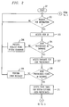
- FIGS. 2 and 3 illustrate, in flowchart form, operations performed by an embodiment of an information system
- FIG. 4 illustrates, in flowchart form, operations performed by an embodiment of a unit utilized to establish information system preferences for a user
- FIG. 5 illustrates, in block diagram form, an embodiment of an information system.
- FIG. 1 illustrates an embodiment for implementing the invention.
- Voice mail system 108 provides voice mail support for enterprise switching system 104.
- Voice mail system 109 provides voice mail support for public telephone switching network 106.
- voice mail system 111 is providing voice mail support for wireless switching system 107.
- Voice mail systems normally provide an user interface by implementing interactive voice response functions although other types of user interfaces to voice mail systems are known to ones skilled in the art.
- Another type of telecommunication response system illustrated in FIG. 1, is interactive voice response systems 118-119 that provides interactive voice response functions for systems other than voice mail systems.
- Interactive voice response system 117 provides the voice response functions for public telephone switching network 106.
- One skilled in the art would readily realize that there could be a plurality of information voice response units attached to any of the switching systems (104, 106 and 107) illustrated in FIG. 1.
- Interactive voice response unit 118 provides support for the enterprise switching system 104
- interactive voice response unit 119 provides support for wireless switching system 107.
- a user can access the voice mail systems 108-111 via telephone sets 101-103. Within FIG. 1, it is assumed that one user is assigned telephones 101-103. In general, any of the telephones can be utilized to access any of the voice mail systems as is well know to those skilled in the art.
- voice mail system 109 interrogates database 114 to obtain the operational preferences of the user.
- the interconnection between a voice mail system and database 114 may be done in a variety of ways. For example, it may be through the public telephone switching network 106 (as illustrated by dashed lines), wide area network 112 (as illustrated by dashed lines), or other mechanisms.
- Database 114 transmits the user's preference information to voice mail system 109 which then uses this information to interpret and respond to multi-frequencies tones or voice commands being received as the user performs various access operations.
- Voice mail system 109 uses the preference information to translate the received tones or commands to accomplish the access operations desired by the user.
- FIG. 1 illustrates personal computer 113 being interconnected to database 114 via WAN 112; however, one skilled in the art can envision a variety of ways that personal computer 113 could be interconnected to database 114.
- the user does not utilize personal computer 113 or any personal computer, but rather could use various devices such as a cellular phone (such as cellular phone 103), a personal digital assistant (PDA), or other devices known to those skilled in the art.
- Telephone 101, enterprise switching system 104, and voice mail system 108 are assumed to be part of organization 116 and may be located on one or more physical locations controlled by this organization. The organization may be a corporation, government agency, university, etc.
- Database 114 is shown to be one entity in FIG. 1; however, database 114 could be a distributed database. Indeed, database 114 could be incorporated into one of the voice mail systems. In another embodiment, database 114 is not one database but rather a plurality of databases.
- the user specifies the voice mail systems being used by the user when they utilize personal computer 113 to enter information. After finishing entering their operational preferences, the user then actuates the database to contact the voice mail systems that the user is utilizing and to inform the voice mail systems of the location of the operational preference information.
- the database may also immediately transfer the resulting state table defining the preference information to each of the voice mail systems or the voice mail systems may request it when the state table is needed.
- the user will utilize a telephone such as telephone set 101 to inform the voice mail system such as voice mail system 108 of which database should be utilized for obtaining the operational preference information.
- personal computer 113 directly distributes the operational preference information to the voice mail systems and the information is not stored in a database such as database 114.
- personal computer 113 internally stores the operational preference information hence is the database 114 for that particular user.
- a vendor controlling a voice mail system such as system 109 may establish database 114 on a server or internal to the voice mail system to be utilized by other voice mail systems simply to promote the use of voice mail system 109. Indeed the vendor controlling voice mail system 109 may charge for this service.
- a Regional Bell Operating Company may establish database 114 that could be accessed from a variety of geographical locations and also charge a fee for the users to utilize the database.
- the database may be established by one of the large Internet provider services such as America Online or Earthlink to promote the utilization of their Internet service. In which case, the user would access their operational preference data via the Internet such that WAN 112 would actually be the Internet itself.
- FIGS. 2 and 3 illustrate the operations performed by an embodiment of an information system such as a voice messaging system or an interactive voice response system.
- an information system such as a voice messaging system or an interactive voice response system.
- such a system could be one of the voice mail systems 108-111 or one of the interactive voice response systems 117-119.
- the information system determines if it is receiving a request for information in decision block 202. If the answer is no, decision block 202 is re-executed. If the answer is yes in decision block 202, the information system accesses in block 203 the user ID that the information system has stored for the user before transferring control to decision block 204. The latter decision block accesses a database such as database 114 to determine if the user has preferences stored within the database. If the answer is no, the information system attempts to process the information request using the normal system commands of the information system before transferring control back to decision block 202.
- block 207 accesses the database for the user's preferences.
- Decision block 208 determines if the user's preferences were found within the database. If the answer is no, block 209 performs error recovery before transferring control back to decision block 202. If the answer in decision block 208 is yes, block 211 accesses the state table for the information system defining the user's preferences. Note, if the preferred information system is the information system executing FIGS. 2 and 3, the state table access will simply do a one for one mapping of the preference commands received from the user into those of the information system. In addition, the user can create a state table defining different preferences that can also be stored in the information system. One skilled in the art could readily envision how the user could create such a table.
- Block 301 initializes the state table to transform the user preference commands to the system commands utilized by the information system executing the operations of FIGS. 2 and 3.
- block 302 receives the first command from the user which is called a preference command.
- decision block 303 determines if the preference command has a match within the state table. If the answer is no, this may mean that in order for a full match to be found in the state table, it may take more than one reference command in order to represent one system command. For example, in voice messaging systems, some systems allow the deletion of a message with one key push on a DTMF dialing pad where as others require the actuation of two keys or sometimes even three keys before the message will be deleted.
- decision block 304 determines if another preference command is needed according to the state table in order to result in a system command. If the answer is yes, control is transferred back to block 302. If the answer in decision block 304 is no, block 307 performs error recovery. It may well be that this particular information system does not provide the desired function that the user is attempting to actuate or the user may have simply made a mistake.
- decision block 306 executes the resulting system command obtained from the state table.
- decision block 308 determines if the information request is done. For example, this can be the result of the user hanging up the telephone or by inputting an input which signals that the information request is over. If the answer in decision block 308 is no, control is transferred back to block 302. If the answer is yes, control is transferred back to decision block 202 of FIG. 2.
- FIG. 4 illustrates, in flowchart form, operations performed by an embodiment of a device utilized by a user to determine their preferred system in database 114.
- This device may be a personal computer, such as personal computer 113 of FIG. 1, or may be any other type of device that can be utilized for this purpose such as a cellular telephone or a personal digital assistant.
- decision block 402 determines if the operation to be performed by the device is to configure access to information systems. If the answer is no, block 403 performs whatever normal processing is done by the device. If the answer in decision block 402 is yes, block 404 accesses the identity of the available information systems for the user from database 114. In block 406, the user selects the preferred information system.
- the user determines the operations that will be utilized to access the other information systems.
- the user selects the other systems used by the user.
- the device transmits the selections to the database in block 408.
- the device determines in decision block 409 whether the selections have been accepted by the database.
- the database performs a concurrent operation in verifying that the selected information systems are indeed available and that the user is authorized to utilize these systems. If the decision in decision block 409 is no, control is transferred to block 411 which performs error recovery before transferring control to block 412. If the answer in decision block 409 is yes, the operations are done as indicated by block 412.
- FIG. 5 illustrates a block diagram of a voice messaging system 501.
- Overall control of voice messaging system 501 is performed by control computer 503 executing programs and utilizing data stored in memory 502.
- Operating system 508 provides the overall control.
- Audio processing control application 509 controls the processing and response to audio information which is received from audio processing unit 506.
- User interface control application 511 is responsible for interpreting and performing the actions required by the user as the user inputs this control information via switch 504 from the switching system as was described with respect to FIG. 1.
- the switching system listed in FIG. 5 can be switching system 104, 102 or 103 of FIG. 1.
- Device control application 512 provides the lower level control for switch 504, audio processing 506 and mass storage 507.
- Audio processing unit 506 performs the audio processing such as conversion of audio information to digital information and digital information to audio information. In addition, audio processing unit 506 also performs the conversion of DTMF signals being received from the switching system via switch 504. As is well known to those skilled in the art, audio processing unit 506 may comprise a plurality of digital signal processors for performing the audio processing task.
- voice messages are stored in mass storage 507 under control of control computer 503.
- Control computer 503 can also utilize storage within mass storage 507 for other types of information.
- Interface 519 under control of control computer 503 provides an interface to database 114 such that control computer 503 can access and store information on database 114.
- Switch 504 is responsible for both digital and audio information being received from the switching system to properly route this to the various subunits of audio processing unit 506 as well as to route switching information to control computer 503.
- the operation and construction of switch 504 is well known to those skilled in the art.
- the interconnection between the switching system and switch 504 may be a plurality of various types of telecommunication links as is well known in the art.
- control computer 503 determines if the user attempting to obtain information is listed in user ID table 518. If the answer is yes, control computer 503 accesses database 114 to ascertain that the user has preferences stored within database 114. If this is true, control computer 503 accesses the state table representing the user's preference from database 114 and stores this state table in preference state table 514 which is illustrated as consisting of a plurality of state tables 516 through 517. There is one state table in preference state table 514 for each user who is actively requesting information from voice mail system 501.
- a computer-readable medium is an electronic, magnetic, optical, or other physical device or means that can contain or store a computer program for use by or in connection with a computer related system or method.
- the information system can be embodied in any computer-readable medium for use by or in connection with an instruction execution system, apparatus, or device such as a computer-based system, processor-containing system, or other system that can fetch the instructions from the instruction execution system, apparatus, or device and execute the instructions.
- a "computer-readable medium” can be any means that can store, communicate, propagate, or transport the program for use by or in connection with the instruction execution system, apparatus, or device.
- the computer-readable medium can be, but is not limited to, an electronic, magnetic, optical, electromagnetic, infrared, or semiconductor system, apparatus, device, or propagation medium.
- the computer-readable medium would include the following: an electrical connection (electronic) having one or more wires, a portable computer diskette (magnetic), a random access memory (RAM) (electronic), a read-only memory (ROM) (electronic), an erasable programmable read-only memory (EPROM, EEPROM, or Flash memory) (electronic), an optical fiber (optical), and a portable compact disc read-only memory (CDROM) (optical).
- an electrical connection having one or more wires
- a portable computer diskette magnetic
- RAM random access memory
- ROM read-only memory
- EPROM erasable programmable read-only memory
- Flash memory erasable programmable read-only memory
- CDROM portable compact disc read-only memory
- the computer-readable medium could even be paper or another suitable medium upon which the program is printed, as the program can be electronically captured, for instance, via optical scanning of the paper or other medium, then compiled, interpreted or otherwise processed in a suitable manner if necessary, and then stored in a computer memory.
- the information system can be implemented with any or a combination of the following technologies, which are each well known in the art: a discrete logic circuit(s) having logic gates for implementing logic functions upon data signals, an application specific integrated circuit (ASIC) having appropriate combinational logic gates, a programmable gate array(s) (PGA), a field programmable gate array (FPGA), etc.
- ASIC application specific integrated circuit
- PGA programmable gate array
- FPGA field programmable gate array
Landscapes
- Engineering & Computer Science (AREA)
- Signal Processing (AREA)
- Telephonic Communication Services (AREA)
- Information Transfer Between Computers (AREA)
Abstract
Description
- The present invention relates to operational access of multiple information systems that individually have different access operations.
- Within a similar type of information systems, different manufacturers may have different access operations to obtain or remove the same information. For example, voice mail systems which are controlled either by voice commands or dual-tone multi-frequency (DTMF) tones have varying access operations between different manufacturers, and one manufacturer may not maintain a consistent set of access operations for generations of their voice mail systems. Initially, this was not a problem for the majority of people since most people had at most one voice mail system to interact with. Now with the proliferation of voice mail systems for residential wired lines, cellular/mobile telephone service, and business based voice messaging systems, the average person is faced with having to contend with three or more different voice mail systems on almost a daily basis. This requires the user to remember three different sets of operations to do even simple tasks. Other informational system types also suffer from this type of problem. The end result normally is that the user of these informational systems limits themselves to one or two different operations simply so that they don't have to memorize three different sets. This results in low efficiency of use of these informational systems.
- A method and apparatus for determining operational preferences for a user access to a plurality of telecommunication response systems designating by the user that user operations of one of the plurality of telecommunication response systems will be the operational preferences of the user for all of the plurality of telecommunication response systems; storing the operational preferences for the user; accessing the stored operational preferences by a second one of the plurality of telecommunication response systems for use in communicating with the user during interactions with the user by the second one of plurality of telecommunication response systems; and interpreting user operations by the second one of plurality of telecommunication response systems using the accessed operational preferences.
- FIG. 1 illustrates an embodiment for implementing the invention;
- FIGS. 2 and 3 illustrate, in flowchart form, operations performed by an embodiment of an information system;
- FIG. 4 illustrates, in flowchart form, operations performed by an embodiment of a unit utilized to establish information system preferences for a user; and
- FIG. 5 illustrates, in block diagram form, an embodiment of an information system.
- FIG. 1 illustrates an embodiment for implementing the invention.
Voice mail system 108 provides voice mail support forenterprise switching system 104.Voice mail system 109 provides voice mail support for publictelephone switching network 106. In general, there would be a plurality of voice mail systems providing support for publictelephone switching network 106; but in general, there would only be one voice mail system associated with the public telephone switching network for each user.Voice mail system 111 is providing voice mail support forwireless switching system 107. Voice mail systems normally provide an user interface by implementing interactive voice response functions although other types of user interfaces to voice mail systems are known to ones skilled in the art. Another type of telecommunication response system illustrated in FIG. 1, is interactive voice response systems 118-119 that provides interactive voice response functions for systems other than voice mail systems. Interactivevoice response system 117 provides the voice response functions for publictelephone switching network 106. One skilled in the art would readily realize that there could be a plurality of information voice response units attached to any of the switching systems (104, 106 and 107) illustrated in FIG. 1. Interactivevoice response unit 118 provides support for theenterprise switching system 104, and interactivevoice response unit 119 provides support forwireless switching system 107. - A user can access the voice mail systems 108-111 via telephone sets 101-103. Within FIG. 1, it is assumed that one user is assigned telephones 101-103. In general, any of the telephones can be utilized to access any of the voice mail systems as is well know to those skilled in the art.
When a voice mail system such asvoice mail system 109 is accessed by a user,voice mail system 109 interrogatesdatabase 114 to obtain the operational preferences of the user. The interconnection between a voice mail system anddatabase 114 may be done in a variety of ways. For example, it may be through the public telephone switching network 106 (as illustrated by dashed lines), wide area network 112 (as illustrated by dashed lines), or other mechanisms.Database 114 transmits the user's preference information tovoice mail system 109 which then uses this information to interpret and respond to multi-frequencies tones or voice commands being received as the user performs various access operations.Voice mail system 109 uses the preference information to translate the received tones or commands to accomplish the access operations desired by the user. - The user establishes their preference information in
database 114 by utilizing an input device such aspersonal computer 113 to tailor their operational preference information indatabase 114. In one embodiment, the information is stored indatabase 114 utilizing the expert markup language (XML). FIG. 1 illustratespersonal computer 113 being interconnected todatabase 114 via WAN 112; however, one skilled in the art can envision a variety of ways thatpersonal computer 113 could be interconnected todatabase 114. In other embodiments, the user does not utilizepersonal computer 113 or any personal computer, but rather could use various devices such as a cellular phone (such as cellular phone 103), a personal digital assistant (PDA), or other devices known to those skilled in the art.Telephone 101,enterprise switching system 104, andvoice mail system 108 are assumed to be part oforganization 116 and may be located on one or more physical locations controlled by this organization. The organization may be a corporation, government agency, university, etc. -
Database 114 is shown to be one entity in FIG. 1; however,database 114 could be a distributed database. Indeed,database 114 could be incorporated into one of the voice mail systems. In another embodiment,database 114 is not one database but rather a plurality of databases. The user specifies the voice mail systems being used by the user when they utilizepersonal computer 113 to enter information. After finishing entering their operational preferences, the user then actuates the database to contact the voice mail systems that the user is utilizing and to inform the voice mail systems of the location of the operational preference information. The database may also immediately transfer the resulting state table defining the preference information to each of the voice mail systems or the voice mail systems may request it when the state table is needed. In another embodiment, the user will utilize a telephone such astelephone set 101 to inform the voice mail system such asvoice mail system 108 of which database should be utilized for obtaining the operational preference information. In yet another embodiment,personal computer 113 directly distributes the operational preference information to the voice mail systems and the information is not stored in a database such asdatabase 114. In yet another embodiment,personal computer 113 internally stores the operational preference information hence is thedatabase 114 for that particular user. In an embodiment, a vendor controlling a voice mail system such assystem 109 may establishdatabase 114 on a server or internal to the voice mail system to be utilized by other voice mail systems simply to promote the use ofvoice mail system 109. Indeed the vendor controllingvoice mail system 109 may charge for this service. In addition, a Regional Bell Operating Company may establishdatabase 114 that could be accessed from a variety of geographical locations and also charge a fee for the users to utilize the database. In addition, the database may be established by one of the large Internet provider services such as America Online or Earthlink to promote the utilization of their Internet service. In which case, the user would access their operational preference data via the Internet such that WAN 112 would actually be the Internet itself. - FIGS. 2 and 3 illustrate the operations performed by an embodiment of an information system such as a voice messaging system or an interactive voice response system. In FIG. 1, such a system could be one of the voice mail systems 108-111 or one of the interactive voice response systems 117-119. Once started in
block 201, the information system determines if it is receiving a request for information indecision block 202. If the answer is no,decision block 202 is re-executed. If the answer is yes indecision block 202, the information system accesses inblock 203 the user ID that the information system has stored for the user before transferring control todecision block 204. The latter decision block accesses a database such asdatabase 114 to determine if the user has preferences stored within the database. If the answer is no, the information system attempts to process the information request using the normal system commands of the information system before transferring control back todecision block 202. - If the answer in
decision block 204 is yes,block 207 accesses the database for the user's preferences.Decision block 208 then determines if the user's preferences were found within the database. If the answer is no, block 209 performs error recovery before transferring control back todecision block 202. If the answer indecision block 208 is yes, block 211 accesses the state table for the information system defining the user's preferences. Note, if the preferred information system is the information system executing FIGS. 2 and 3, the state table access will simply do a one for one mapping of the preference commands received from the user into those of the information system. In addition, the user can create a state table defining different preferences that can also be stored in the information system. One skilled in the art could readily envision how the user could create such a table. - After execution of
block 211, control is transferred to block 301 of FIG. 3.Block 301 initializes the state table to transform the user preference commands to the system commands utilized by the information system executing the operations of FIGS. 2 and 3. After execution ofblock 301, block 302 receives the first command from the user which is called a preference command. After the preference command is received,decision block 303 determines if the preference command has a match within the state table. If the answer is no, this may mean that in order for a full match to be found in the state table, it may take more than one reference command in order to represent one system command. For example, in voice messaging systems, some systems allow the deletion of a message with one key push on a DTMF dialing pad where as others require the actuation of two keys or sometimes even three keys before the message will be deleted. - If the answer is no in
decision block 303,decision block 304 determines if another preference command is needed according to the state table in order to result in a system command. If the answer is yes, control is transferred back to block 302. If the answer indecision block 304 is no, block 307 performs error recovery. It may well be that this particular information system does not provide the desired function that the user is attempting to actuate or the user may have simply made a mistake. - Returning to decision block 303, if the answer is yes, block 306 executes the resulting system command obtained from the state table. Finally,
decision block 308 determines if the information request is done. For example, this can be the result of the user hanging up the telephone or by inputting an input which signals that the information request is over. If the answer indecision block 308 is no, control is transferred back to block 302. If the answer is yes, control is transferred back to decision block 202 of FIG. 2. - FIG. 4 illustrates, in flowchart form, operations performed by an embodiment of a device utilized by a user to determine their preferred system in
database 114. This device may be a personal computer, such aspersonal computer 113 of FIG. 1, or may be any other type of device that can be utilized for this purpose such as a cellular telephone or a personal digital assistant. Once started inblock 401,decision block 402 determines if the operation to be performed by the device is to configure access to information systems. If the answer is no, block 403 performs whatever normal processing is done by the device. If the answer indecision block 402 is yes, block 404 accesses the identity of the available information systems for the user fromdatabase 114. Inblock 406, the user selects the preferred information system. By selecting the preferred information system, the user determines the operations that will be utilized to access the other information systems. Next, inblock 407, the user selects the other systems used by the user. Finally, the device transmits the selections to the database inblock 408. The device determines indecision block 409 whether the selections have been accepted by the database. The database performs a concurrent operation in verifying that the selected information systems are indeed available and that the user is authorized to utilize these systems. If the decision indecision block 409 is no, control is transferred to block 411 which performs error recovery before transferring control to block 412. If the answer indecision block 409 is yes, the operations are done as indicated byblock 412. - FIG. 5 illustrates a block diagram of a
voice messaging system 501. Overall control ofvoice messaging system 501 is performed bycontrol computer 503 executing programs and utilizing data stored inmemory 502.
Operating system 508 provides the overall control. Audioprocessing control application 509 controls the processing and response to audio information which is received fromaudio processing unit 506. Userinterface control application 511 is responsible for interpreting and performing the actions required by the user as the user inputs this control information viaswitch 504 from the switching system as was described with respect to FIG. 1. The switching system listed in FIG. 5 can be switchingsystem Device control application 512 provides the lower level control forswitch 504,audio processing 506 andmass storage 507. -
Audio processing unit 506 performs the audio processing such as conversion of audio information to digital information and digital information to audio information. In addition,audio processing unit 506 also performs the conversion of DTMF signals being received from the switching system viaswitch 504. As is well known to those skilled in the art,audio processing unit 506 may comprise a plurality of digital signal processors for performing the audio processing task. - After being converted to digital form by
audio processing unit 506, voice messages are stored inmass storage 507 under control ofcontrol computer 503.Control computer 503 can also utilize storage withinmass storage 507 for other types of information.Interface 519 under control ofcontrol computer 503 provides an interface todatabase 114 such thatcontrol computer 503 can access and store information ondatabase 114. -
Switch 504 is responsible for both digital and audio information being received from the switching system to properly route this to the various subunits ofaudio processing unit 506 as well as to route switching information to controlcomputer 503. The operation and construction ofswitch 504 is well known to those skilled in the art. The interconnection between the switching system and switch 504 may be a plurality of various types of telecommunication links as is well known in the art. - As was described with respect to the operations of FIG. 2, when
control computer 503 receives a request for information viaswitch 504 and/oraudio processing unit 506,control computer 503 determines if the user attempting to obtain information is listed in user ID table 518. If the answer is yes, controlcomputer 503 accessesdatabase 114 to ascertain that the user has preferences stored withindatabase 114. If this is true,control computer 503 accesses the state table representing the user's preference fromdatabase 114 and stores this state table in preference state table 514 which is illustrated as consisting of a plurality of state tables 516 through 517. There is one state table in preference state table 514 for each user who is actively requesting information fromvoice mail system 501. - When the operations of an information system are implemented in software, it should be noted that the software can be stored on any computer-readable medium for use by or in connection with any computer related system or method. In the context of this document, a computer-readable medium is an electronic, magnetic, optical, or other physical device or means that can contain or store a computer program for use by or in connection with a computer related system or method. The information system can be embodied in any computer-readable medium for use by or in connection with an instruction execution system, apparatus, or device such as a computer-based system, processor-containing system, or other system that can fetch the instructions from the instruction execution system, apparatus, or device and execute the instructions. In the context of this document, a "computer-readable medium" can be any means that can store, communicate, propagate, or transport the program for use by or in connection with the instruction execution system, apparatus, or device. For example, the computer-readable medium can be, but is not limited to, an electronic, magnetic, optical, electromagnetic, infrared, or semiconductor system, apparatus, device, or propagation medium. More specific examples (a non-exhaustive list) of the computer-readable medium would include the following: an electrical connection (electronic) having one or more wires, a portable computer diskette (magnetic), a random access memory (RAM) (electronic), a read-only memory (ROM) (electronic), an erasable programmable read-only memory (EPROM, EEPROM, or Flash memory) (electronic), an optical fiber (optical), and a portable compact disc read-only memory (CDROM) (optical). Note that the computer-readable medium could even be paper or another suitable medium upon which the program is printed, as the program can be electronically captured, for instance, via optical scanning of the paper or other medium, then compiled, interpreted or otherwise processed in a suitable manner if necessary, and then stored in a computer memory.
- In an alternative embodiment, where the information system is implemented in hardware, the information system can be implemented with any or a combination of the following technologies, which are each well known in the art: a discrete logic circuit(s) having logic gates for implementing logic functions upon data signals, an application specific integrated circuit (ASIC) having appropriate combinational logic gates, a programmable gate array(s) (PGA), a field programmable gate array (FPGA), etc.
Claims (10)
- A method of determining operational preferences for a user access to a plurality of telecommunication response systems, comprising the steps of:CHARACTERIZED IN THATdesignating (402-407) by the user that user operations of one of the plurality of telecommunication response systems will be the operational preferences of the user for all of the plurality of telecommunication response systems;storing (409, 412) the operational preferences for the user;accessing (202-211) the stored operational preferences by a second one of the plurality of telecommunication response systems for use in communicating with the user during interactions with the user by the second one of plurality of telecommunication response systems; andinterpreting (301-306) user operations by the second one of plurality of telecommunication response systems using the accessed operational preferences.
- The method of claim 1 wherein the step of designating comprises the steps of identifying (404) the one of the plurality of telecommunication response systems by the user; and
specifying (407) the other ones of the plurality of telecommunication response systems by the user. - The method of claim 1 wherein the step of storing comprises the step of storing (408, 409) the operational preferences in a database.
- The method of claim 1 wherein the step of accessing is performed each time the user communicates with the second one of the plurality of telecommunication response systems.
- The method of claim 1 wherein the step of accessing is performed only a first time the user communicates with the second one of the plurality of telecommunication response systems.
- A processor-readable medium 502) for determining operational preferences for a user access to a plurality of telecommunication response systems, comprising processor-executable instructions (509, 511) configured:CHARACTERIZED IN THATdesignating (402-407) by the user that user operations of one of the plurality of telecommunication response systems will be the operational preferences of the user for all of the plurality of telecommunication response systems;storing (409, 412) the operational preferences for the user;accessing (202-211) the stored operational preferences by a second one of the plurality of telecommunication response systems for use in communicating with the user during interactions with the user by the second one of plurality of telecommunication response systems; andinterpreting (301-306) user operations by the second one of plurality of telecommunication response systems using the accessed operational preferences.
- The processor-readable medium of claim 6 wherein the processor-readable medium for designating comprises processor-readable medium for identifying (404) the one of the plurality of telecommunication response systems by the user; and
specifying (407) the other ones of the plurality of telecommunication response systems by the user. - The processor-readable medium of claim 7 wherein the processor-readable medium for identifying and specifying use a telephone.
- The processor-readable medium of claim 7 wherein the processor-readable medium for identifying and specifying use at least one of a personal computer or personal digital assistant.
- The processor-readable medium of claim 6 wherein the processor-readable medium for storing comprises processor-readable medium for storing (408, 409) the operational preferences in a database.
Applications Claiming Priority (1)
| Application Number | Priority Date | Filing Date | Title |
|---|---|---|---|
| US10/923,489 US7359495B2 (en) | 2004-08-20 | 2004-08-20 | Method and apparatus for uniform operational access across multiple information systems |
Publications (1)
| Publication Number | Publication Date |
|---|---|
| EP1628461A1 true EP1628461A1 (en) | 2006-02-22 |
Family
ID=35335688
Family Applications (1)
| Application Number | Title | Priority Date | Filing Date |
|---|---|---|---|
| EP05254790A Withdrawn EP1628461A1 (en) | 2004-08-20 | 2005-07-29 | Method and apparatus for uniform operational access across multiple information systems |
Country Status (4)
| Country | Link |
|---|---|
| US (1) | US7359495B2 (en) |
| EP (1) | EP1628461A1 (en) |
| JP (1) | JP4490887B2 (en) |
| CA (1) | CA2514365A1 (en) |
Families Citing this family (3)
| Publication number | Priority date | Publication date | Assignee | Title |
|---|---|---|---|---|
| US7983723B2 (en) * | 2005-06-15 | 2011-07-19 | Sony Ericsson Mobile Communications Ab | Closed mode user interface for wireless communication devices |
| US8625750B2 (en) * | 2010-12-23 | 2014-01-07 | Cox Communications, Inc. | Call screening for voicemail |
| US8605871B2 (en) * | 2011-08-10 | 2013-12-10 | Blackberry Limited | Methods and apparatus to send voice messages |
Citations (2)
| Publication number | Priority date | Publication date | Assignee | Title |
|---|---|---|---|---|
| WO2000074358A2 (en) | 1999-06-01 | 2000-12-07 | Evoice, Inc. | Voice messaging system |
| GB2395394A (en) * | 2002-11-08 | 2004-05-19 | Hewlett Packard Co | Voice mail network where changes to one voicemail system are recorded centrally at an administrator and used to update other voicemail system databases |
Family Cites Families (3)
| Publication number | Priority date | Publication date | Assignee | Title |
|---|---|---|---|---|
| US5243643A (en) * | 1990-11-01 | 1993-09-07 | Voiceples Corporation | Voice processing system with configurable caller interfaces |
| US6229880B1 (en) * | 1998-05-21 | 2001-05-08 | Bell Atlantic Network Services, Inc. | Methods and apparatus for efficiently providing a communication system with speech recognition capabilities |
| US7180985B2 (en) * | 2003-08-27 | 2007-02-20 | International Business Machines Corporation | Interactive voice response (IVR) aggregation master service |
-
2004
- 2004-08-20 US US10/923,489 patent/US7359495B2/en active Active
-
2005
- 2005-07-29 CA CA002514365A patent/CA2514365A1/en not_active Abandoned
- 2005-07-29 EP EP05254790A patent/EP1628461A1/en not_active Withdrawn
- 2005-08-19 JP JP2005238364A patent/JP4490887B2/en not_active Expired - Fee Related
Patent Citations (2)
| Publication number | Priority date | Publication date | Assignee | Title |
|---|---|---|---|---|
| WO2000074358A2 (en) | 1999-06-01 | 2000-12-07 | Evoice, Inc. | Voice messaging system |
| GB2395394A (en) * | 2002-11-08 | 2004-05-19 | Hewlett Packard Co | Voice mail network where changes to one voicemail system are recorded centrally at an administrator and used to update other voicemail system databases |
Also Published As
| Publication number | Publication date |
|---|---|
| CA2514365A1 (en) | 2006-02-20 |
| US20060050855A1 (en) | 2006-03-09 |
| US7359495B2 (en) | 2008-04-15 |
| JP4490887B2 (en) | 2010-06-30 |
| JP2006060821A (en) | 2006-03-02 |
Similar Documents
| Publication | Publication Date | Title |
|---|---|---|
| US7254384B2 (en) | Multi-modal messaging | |
| US6788770B1 (en) | Intelligent voice response system with navigator database | |
| US7477907B2 (en) | Universal call control systems and methods | |
| EP0697780B1 (en) | Voice response system | |
| CN101188644A (en) | Bank voice service method and system | |
| US5819046A (en) | System for invoking in computer application associated with second user connected to the computer and subject to any active conditions associated with the second user | |
| CN105718267B (en) | A kind of more apply merges into the implementation method singly applied and its realization system | |
| WO1992015166A1 (en) | Integrated application controlled call processing and messaging system | |
| KR20160010190A (en) | Method for message automatic response service | |
| US8571199B2 (en) | Method and apparatus for proper routing of customers | |
| CA2216762C (en) | Methods for automatic service provisioning for telecommunications | |
| EP1001591B1 (en) | Redundant database storage of selected record information for an automated interrogation device | |
| CN101150775A (en) | A system and method for realizing platform-cross interaction of mobile terminal music service | |
| JP2005518765A (en) | How to operate a spoken dialogue system | |
| WO2003060881A1 (en) | My voice voice agent for use with voice portails and related products | |
| US7359495B2 (en) | Method and apparatus for uniform operational access across multiple information systems | |
| US6795537B1 (en) | Method for updating a database using a telephone | |
| KR101095232B1 (en) | Selective Spam Blocking Method for Mobile Devices | |
| EP3244333B1 (en) | Method and device for concealing personal information on calling interface | |
| US7328257B2 (en) | System for automatically assigning a telephone number to an existing telephone after detecting a network connection of a portable computer | |
| CN101026650A (en) | Communication service access system and method | |
| CN101299681B (en) | A query type intelligent business data system and its implementation method | |
| CN101902533A (en) | Telephone Book Management System Based on Intelligent Network | |
| JP2006185319A (en) | Customer support support method and customer support support system | |
| EP1496677A1 (en) | Communication apparatus having programmable soft keys and method of programming such soft keys |
Legal Events
| Date | Code | Title | Description |
|---|---|---|---|
| PUAI | Public reference made under article 153(3) epc to a published international application that has entered the european phase |
Free format text: ORIGINAL CODE: 0009012 |
|
| AK | Designated contracting states |
Kind code of ref document: A1 Designated state(s): AT BE BG CH CY CZ DE DK EE ES FI FR GB GR HU IE IS IT LI LT LU LV MC NL PL PT RO SE SI SK TR |
|
| AX | Request for extension of the european patent |
Extension state: AL BA HR MK YU |
|
| 17P | Request for examination filed |
Effective date: 20060727 |
|
| 17Q | First examination report despatched |
Effective date: 20060829 |
|
| AKX | Designation fees paid |
Designated state(s): DE FR GB |
|
| RAP1 | Party data changed (applicant data changed or rights of an application transferred) |
Owner name: AVAYA INC. |
|
| STAA | Information on the status of an ep patent application or granted ep patent |
Free format text: STATUS: THE APPLICATION IS DEEMED TO BE WITHDRAWN |
|
| 18D | Application deemed to be withdrawn |
Effective date: 20140603 |