EP1628362B1 - Heating sleeve for shrinking on of shrink tube connections - Google Patents
Heating sleeve for shrinking on of shrink tube connections Download PDFInfo
- Publication number
- EP1628362B1 EP1628362B1 EP20050017290 EP05017290A EP1628362B1 EP 1628362 B1 EP1628362 B1 EP 1628362B1 EP 20050017290 EP20050017290 EP 20050017290 EP 05017290 A EP05017290 A EP 05017290A EP 1628362 B1 EP1628362 B1 EP 1628362B1
- Authority
- EP
- European Patent Office
- Prior art keywords
- shrink tube
- heating element
- temperature
- elements
- shrinking
- Prior art date
- Legal status (The legal status is an assumption and is not a legal conclusion. Google has not performed a legal analysis and makes no representation as to the accuracy of the status listed.)
- Expired - Lifetime
Links
Images
Classifications
-
- B—PERFORMING OPERATIONS; TRANSPORTING
- B29—WORKING OF PLASTICS; WORKING OF SUBSTANCES IN A PLASTIC STATE IN GENERAL
- B29C—SHAPING OR JOINING OF PLASTICS; SHAPING OF MATERIAL IN A PLASTIC STATE, NOT OTHERWISE PROVIDED FOR; AFTER-TREATMENT OF THE SHAPED PRODUCTS, e.g. REPAIRING
- B29C65/00—Joining or sealing of preformed parts, e.g. welding of plastics materials; Apparatus therefor
- B29C65/02—Joining or sealing of preformed parts, e.g. welding of plastics materials; Apparatus therefor by heating, with or without pressure
- B29C65/18—Joining or sealing of preformed parts, e.g. welding of plastics materials; Apparatus therefor by heating, with or without pressure using heated tools
-
- B—PERFORMING OPERATIONS; TRANSPORTING
- B29—WORKING OF PLASTICS; WORKING OF SUBSTANCES IN A PLASTIC STATE IN GENERAL
- B29C—SHAPING OR JOINING OF PLASTICS; SHAPING OF MATERIAL IN A PLASTIC STATE, NOT OTHERWISE PROVIDED FOR; AFTER-TREATMENT OF THE SHAPED PRODUCTS, e.g. REPAIRING
- B29C65/00—Joining or sealing of preformed parts, e.g. welding of plastics materials; Apparatus therefor
- B29C65/66—Joining or sealing of preformed parts, e.g. welding of plastics materials; Apparatus therefor by liberation of internal stresses, e.g. shrinking of one of the parts to be joined
- B29C65/68—Joining or sealing of preformed parts, e.g. welding of plastics materials; Apparatus therefor by liberation of internal stresses, e.g. shrinking of one of the parts to be joined using auxiliary shrinkable elements
-
- B—PERFORMING OPERATIONS; TRANSPORTING
- B29—WORKING OF PLASTICS; WORKING OF SUBSTANCES IN A PLASTIC STATE IN GENERAL
- B29C—SHAPING OR JOINING OF PLASTICS; SHAPING OF MATERIAL IN A PLASTIC STATE, NOT OTHERWISE PROVIDED FOR; AFTER-TREATMENT OF THE SHAPED PRODUCTS, e.g. REPAIRING
- B29C66/00—General aspects of processes or apparatus for joining preformed parts
- B29C66/01—General aspects dealing with the joint area or with the area to be joined
- B29C66/05—Particular design of joint configurations
- B29C66/10—Particular design of joint configurations particular design of the joint cross-sections
- B29C66/11—Joint cross-sections comprising a single joint-segment, i.e. one of the parts to be joined comprising a single joint-segment in the joint cross-section
- B29C66/112—Single lapped joints
- B29C66/1122—Single lap to lap joints, i.e. overlap joints
-
- B—PERFORMING OPERATIONS; TRANSPORTING
- B29—WORKING OF PLASTICS; WORKING OF SUBSTANCES IN A PLASTIC STATE IN GENERAL
- B29C—SHAPING OR JOINING OF PLASTICS; SHAPING OF MATERIAL IN A PLASTIC STATE, NOT OTHERWISE PROVIDED FOR; AFTER-TREATMENT OF THE SHAPED PRODUCTS, e.g. REPAIRING
- B29C66/00—General aspects of processes or apparatus for joining preformed parts
- B29C66/50—General aspects of joining tubular articles; General aspects of joining long products, i.e. bars or profiled elements; General aspects of joining single elements to tubular articles, hollow articles or bars; General aspects of joining several hollow-preforms to form hollow or tubular articles
- B29C66/51—Joining tubular articles, profiled elements or bars; Joining single elements to tubular articles, hollow articles or bars; Joining several hollow-preforms to form hollow or tubular articles
- B29C66/52—Joining tubular articles, bars or profiled elements
- B29C66/522—Joining tubular articles
- B29C66/5221—Joining tubular articles for forming coaxial connections, i.e. the tubular articles to be joined forming a zero angle relative to each other
-
- B—PERFORMING OPERATIONS; TRANSPORTING
- B29—WORKING OF PLASTICS; WORKING OF SUBSTANCES IN A PLASTIC STATE IN GENERAL
- B29C—SHAPING OR JOINING OF PLASTICS; SHAPING OF MATERIAL IN A PLASTIC STATE, NOT OTHERWISE PROVIDED FOR; AFTER-TREATMENT OF THE SHAPED PRODUCTS, e.g. REPAIRING
- B29C66/00—General aspects of processes or apparatus for joining preformed parts
- B29C66/80—General aspects of machine operations or constructions and parts thereof
- B29C66/81—General aspects of the pressing elements, i.e. the elements applying pressure on the parts to be joined in the area to be joined, e.g. the welding jaws or clamps
- B29C66/812—General aspects of the pressing elements, i.e. the elements applying pressure on the parts to be joined in the area to be joined, e.g. the welding jaws or clamps characterised by the composition, by the structure, by the intensive physical properties or by the optical properties of the material constituting the pressing elements, e.g. constituting the welding jaws or clamps
- B29C66/8122—General aspects of the pressing elements, i.e. the elements applying pressure on the parts to be joined in the area to be joined, e.g. the welding jaws or clamps characterised by the composition, by the structure, by the intensive physical properties or by the optical properties of the material constituting the pressing elements, e.g. constituting the welding jaws or clamps characterised by the composition of the material constituting the pressing elements, e.g. constituting the welding jaws or clamps
-
- B—PERFORMING OPERATIONS; TRANSPORTING
- B29—WORKING OF PLASTICS; WORKING OF SUBSTANCES IN A PLASTIC STATE IN GENERAL
- B29C—SHAPING OR JOINING OF PLASTICS; SHAPING OF MATERIAL IN A PLASTIC STATE, NOT OTHERWISE PROVIDED FOR; AFTER-TREATMENT OF THE SHAPED PRODUCTS, e.g. REPAIRING
- B29C66/00—General aspects of processes or apparatus for joining preformed parts
- B29C66/80—General aspects of machine operations or constructions and parts thereof
- B29C66/81—General aspects of the pressing elements, i.e. the elements applying pressure on the parts to be joined in the area to be joined, e.g. the welding jaws or clamps
- B29C66/814—General aspects of the pressing elements, i.e. the elements applying pressure on the parts to be joined in the area to be joined, e.g. the welding jaws or clamps characterised by the design of the pressing elements, e.g. of the welding jaws or clamps
- B29C66/8145—General aspects of the pressing elements, i.e. the elements applying pressure on the parts to be joined in the area to be joined, e.g. the welding jaws or clamps characterised by the design of the pressing elements, e.g. of the welding jaws or clamps characterised by the constructional aspects of the pressing elements, e.g. of the welding jaws or clamps
- B29C66/81471—General aspects of the pressing elements, i.e. the elements applying pressure on the parts to be joined in the area to be joined, e.g. the welding jaws or clamps characterised by the design of the pressing elements, e.g. of the welding jaws or clamps characterised by the constructional aspects of the pressing elements, e.g. of the welding jaws or clamps being a wrap-around tape or band
-
- B—PERFORMING OPERATIONS; TRANSPORTING
- B29—WORKING OF PLASTICS; WORKING OF SUBSTANCES IN A PLASTIC STATE IN GENERAL
- B29C—SHAPING OR JOINING OF PLASTICS; SHAPING OF MATERIAL IN A PLASTIC STATE, NOT OTHERWISE PROVIDED FOR; AFTER-TREATMENT OF THE SHAPED PRODUCTS, e.g. REPAIRING
- B29C66/00—General aspects of processes or apparatus for joining preformed parts
- B29C66/90—Measuring or controlling the joining process
- B29C66/91—Measuring or controlling the joining process by measuring or controlling the temperature, the heat or the thermal flux
- B29C66/912—Measuring or controlling the joining process by measuring or controlling the temperature, the heat or the thermal flux by measuring the temperature, the heat or the thermal flux
- B29C66/9121—Measuring or controlling the joining process by measuring or controlling the temperature, the heat or the thermal flux by measuring the temperature, the heat or the thermal flux by measuring the temperature
- B29C66/91231—Measuring or controlling the joining process by measuring or controlling the temperature, the heat or the thermal flux by measuring the temperature, the heat or the thermal flux by measuring the temperature of the joining tool
-
- B—PERFORMING OPERATIONS; TRANSPORTING
- B29—WORKING OF PLASTICS; WORKING OF SUBSTANCES IN A PLASTIC STATE IN GENERAL
- B29C—SHAPING OR JOINING OF PLASTICS; SHAPING OF MATERIAL IN A PLASTIC STATE, NOT OTHERWISE PROVIDED FOR; AFTER-TREATMENT OF THE SHAPED PRODUCTS, e.g. REPAIRING
- B29C66/00—General aspects of processes or apparatus for joining preformed parts
- B29C66/90—Measuring or controlling the joining process
- B29C66/91—Measuring or controlling the joining process by measuring or controlling the temperature, the heat or the thermal flux
- B29C66/914—Measuring or controlling the joining process by measuring or controlling the temperature, the heat or the thermal flux by controlling or regulating the temperature, the heat or the thermal flux
- B29C66/9141—Measuring or controlling the joining process by measuring or controlling the temperature, the heat or the thermal flux by controlling or regulating the temperature, the heat or the thermal flux by controlling or regulating the temperature
- B29C66/91421—Measuring or controlling the joining process by measuring or controlling the temperature, the heat or the thermal flux by controlling or regulating the temperature, the heat or the thermal flux by controlling or regulating the temperature of the joining tools
-
- B—PERFORMING OPERATIONS; TRANSPORTING
- B29—WORKING OF PLASTICS; WORKING OF SUBSTANCES IN A PLASTIC STATE IN GENERAL
- B29C—SHAPING OR JOINING OF PLASTICS; SHAPING OF MATERIAL IN A PLASTIC STATE, NOT OTHERWISE PROVIDED FOR; AFTER-TREATMENT OF THE SHAPED PRODUCTS, e.g. REPAIRING
- B29C66/00—General aspects of processes or apparatus for joining preformed parts
- B29C66/90—Measuring or controlling the joining process
- B29C66/91—Measuring or controlling the joining process by measuring or controlling the temperature, the heat or the thermal flux
- B29C66/914—Measuring or controlling the joining process by measuring or controlling the temperature, the heat or the thermal flux by controlling or regulating the temperature, the heat or the thermal flux
- B29C66/9141—Measuring or controlling the joining process by measuring or controlling the temperature, the heat or the thermal flux by controlling or regulating the temperature, the heat or the thermal flux by controlling or regulating the temperature
- B29C66/91441—Measuring or controlling the joining process by measuring or controlling the temperature, the heat or the thermal flux by controlling or regulating the temperature, the heat or the thermal flux by controlling or regulating the temperature the temperature being non-constant over time
- B29C66/91443—Measuring or controlling the joining process by measuring or controlling the temperature, the heat or the thermal flux by controlling or regulating the temperature, the heat or the thermal flux by controlling or regulating the temperature the temperature being non-constant over time following a temperature-time profile
- B29C66/91445—Measuring or controlling the joining process by measuring or controlling the temperature, the heat or the thermal flux by controlling or regulating the temperature, the heat or the thermal flux by controlling or regulating the temperature the temperature being non-constant over time following a temperature-time profile by steps
-
- B—PERFORMING OPERATIONS; TRANSPORTING
- B29—WORKING OF PLASTICS; WORKING OF SUBSTANCES IN A PLASTIC STATE IN GENERAL
- B29C—SHAPING OR JOINING OF PLASTICS; SHAPING OF MATERIAL IN A PLASTIC STATE, NOT OTHERWISE PROVIDED FOR; AFTER-TREATMENT OF THE SHAPED PRODUCTS, e.g. REPAIRING
- B29C66/00—General aspects of processes or apparatus for joining preformed parts
- B29C66/90—Measuring or controlling the joining process
- B29C66/91—Measuring or controlling the joining process by measuring or controlling the temperature, the heat or the thermal flux
- B29C66/914—Measuring or controlling the joining process by measuring or controlling the temperature, the heat or the thermal flux by controlling or regulating the temperature, the heat or the thermal flux
- B29C66/9161—Measuring or controlling the joining process by measuring or controlling the temperature, the heat or the thermal flux by controlling or regulating the temperature, the heat or the thermal flux by controlling or regulating the heat or the thermal flux, i.e. the heat flux
- B29C66/91651—Measuring or controlling the joining process by measuring or controlling the temperature, the heat or the thermal flux by controlling or regulating the temperature, the heat or the thermal flux by controlling or regulating the heat or the thermal flux, i.e. the heat flux by controlling or regulating the heat generated by Joule heating or induction heating
-
- B—PERFORMING OPERATIONS; TRANSPORTING
- B29—WORKING OF PLASTICS; WORKING OF SUBSTANCES IN A PLASTIC STATE IN GENERAL
- B29C—SHAPING OR JOINING OF PLASTICS; SHAPING OF MATERIAL IN A PLASTIC STATE, NOT OTHERWISE PROVIDED FOR; AFTER-TREATMENT OF THE SHAPED PRODUCTS, e.g. REPAIRING
- B29C66/00—General aspects of processes or apparatus for joining preformed parts
- B29C66/90—Measuring or controlling the joining process
- B29C66/96—Measuring or controlling the joining process characterised by the method for implementing the controlling of the joining process
- B29C66/961—Measuring or controlling the joining process characterised by the method for implementing the controlling of the joining process involving a feedback loop mechanism, e.g. comparison with a desired value
-
- H—ELECTRICITY
- H01—ELECTRIC ELEMENTS
- H01R—ELECTRICALLY-CONDUCTIVE CONNECTIONS; STRUCTURAL ASSOCIATIONS OF A PLURALITY OF MUTUALLY-INSULATED ELECTRICAL CONNECTING ELEMENTS; COUPLING DEVICES; CURRENT COLLECTORS
- H01R4/00—Electrically-conductive connections between two or more conductive members in direct contact, i.e. touching one another; Means for effecting or maintaining such contact; Electrically-conductive connections having two or more spaced connecting locations for conductors and using contact members penetrating insulation
- H01R4/70—Insulation of connections
- H01R4/72—Insulation of connections using a heat shrinking insulating sleeve
Definitions
- Device for connecting two elements arrangement for connecting two elements; method for producing a device for connecting two elements; method for connecting two elements; and the use of a heating element for shrinking a shrink tube.
- the invention relates to a device for connecting two elements, an arrangement for connecting two elements, a method for producing a device for connecting two elements, a method for connecting two elements, and the use of a heating element for shrinking a shrink tube.
- a shrink tube is used to establish a connection between two elements to be connected.
- shrink tube may relate in particular to a tube made from a thermoplastic material, which tube contracts due to the effect of heat.
- the diameter of the shrink tube is irreversibly reduced under the effect of heat such that the shrunk shrink tube engages the two elements to be connected and thus establishes a connection between the elements.
- a shrink tube is pulled over a region of the abutting elements.
- Heat is applied to the shrink tube by means of an industrial hot-blast device or a Bunsen burner such that as a result of this the diameter of the shrink tube is reduced.
- the shrunk shrink tube thus contracts over the two ends of the elements and in this way forms a mechanical connection of the two elements.
- shrink tubes for connecting elements to be connected plays a role in particular in aircraft because shrink tube connections contribute to keeping the weight of the aircraft down. Furthermore, installation and deinstallation effort is reduced (making four or at least two steel strip clamps dispensible). Moreover, keeping hitherto-used special couplers is no longer necessary for the manufacturer or for the operator.
- an aircraft represents a temperature-sensitive environment in which the use of an open flame or some other strong heat source as used according to the state of the art for producing a shrink tube
- US 5,053,595 and US 4,883,925 disclose a connection system using heat shrink sleeves, wherein two cable elements can be connected via tubular heat schrink sleeves.
- the tubular sleeves are shrinkable when applying thermal energy.
- the thermal energy is applied in US 5,053,595 by using a heatable wire that is wrapped around the shrink sleeve several times or by using a rigid heating element.
- connection is critical.
- stringent safety regulations relating to aircraft regulations which often are not compatible with the use of a Bunsen burner or an industrial hot-blast device. Such basic conditions can also be found in other environments (railways, office blocks, etc.) in which shrink tube connections can be used.
- This object may be solved by a device for connecting two elements, by an arrangement for connecting two elements, by a method for producing a device for connecting two elements, by a method for connecting two elements, and by the use of a heating element for shrinking a shrink tube with the features according to the independent claims.
- the device according to the invention for connecting two elements by means of shrinking a shrink tube comprises a heating element and a control unit.
- the heating element is adapted for providing thermal or inductive energy and is further adapted such that with it a shrink tube, which can be pulled onto a connection region of two elements to be connected, can be encased along at least part of the circumference of the shrink tube.
- the control unit is adapted for supplying electrical energy to the heating element, and is further adapted such that with it the temperature of the heating element can be controlled in such a way that, by means of shrinking the shrink tube, the two elements are connectable.
- an arrangement for connecting a first element to a second element in a connection region by means of a shrink tube, wherein said arrangement comprises a first element, a second element, a shrink tube, a heating element and a control unit.
- the shrink tube is pullable onto a connection region of the first element and the second element.
- the heating element is adapted for providing thermal or inductive energy and is further adapted such that with it the shrink tube can be encased along at least part of the circumference of the shrink tube.
- the control unit is adapted for supplying electrical energy to the heating element and is further adapted such that with it the temperature of the heating element can be controlled such that, by means of shrinking the shrink tube, the first element can be connected to the second element.
- a heating element for providing thermal or inductive energy is formed and adapted such that with it a shrink tube which can be pulled onto a connection region of two elements to be connected can be encased along at least part of the circumference of the shrink tube.
- a control unit is formed for supplying electrical energy to the heating element and is adapted such that with it the temperature of the heating element can be controlled such that, by means of shrinking the shrink tube, the two elements are connectable.
- a method for connecting two elements by means of shrinking a shrink tube in which method a shrink tube is pulled onto a connection region of two elements to be connected, along at least part of its circumference the pulled-on shrink tube is encased by a heating element, and by means of the heating element thermal or inductive energy is supplied to the shrink tube, wherein the temperature of the heating element is controlled such that, by means of shrinking the shrink tube, the two elements are connected.
- a shrink tube is used along at least part of the heating element encasing its circumference to provide thermal or inductive energy for shrinking the shrink tube for connecting two elements onto which in a connection region the shrink tube is pulled.
- a basic idea of the invention may be seen in that a shrink tube for connecting two elements is supplied in a targeted way with a defined quantity of heat required for shrinking, in that the shrink tube is directly encased by a heating element for providing the thermal or inductive energy required for shrinking.
- the shrink tube is brought into direct contact with the heating element such that heat transfer/introduction can take place by means of heat conduction and/or heat radiation and/or heat convection.
- the heat source and the shrink tube are arranged so as to be directly spatially adjacent such that according to the invention the efficiency when supplying thermal or inductive energy for shrinking the shrink tube is significantly improved.
- the shrink tube connection according to the invention can be used even in critical, spatially confined, temperature-sensitive environments, for example in an aircraft.
- the solution according to the invention also meets stringent safety regulations because with the invention the quantity of heat emitted to the surroundings is reduced, and an open fire (as is the case with the use of a Bunsen burner) or a spatially non-confined flow of hot air (as is the case with the use of an industrial hot-blast device) is avoided.
- Application of the invention is therefore particularly advantageous in such scenarios in which due to confined installation space or stringent safety requirements (for example in an aircraft, in which a naked flame must at all costs be avoided, or in which the temperature sensitivity of the surroundings are to be taken into account) shrinking the shrink tube into place by means of an open heat source is problematic.
- the heating element of the invention can be implemented as a heating sleeve for shrinking into place a shrink tube connection.
- a secure lightweight connection between two elements can be implemented by means of a targeted supply of thermal or inductive energy, wherein the overall energy quantity arising and any undesired heating up of the environment are reduced.
- Two elements to be connected onto which elements the shrink tube is pulled, can be positioned such that the shrink tube is aligned by means of markings (for example colour markings) on the elements to be connected.
- a heating element (for example a heating mat) covers the shrink tube in a predefinable connection region, of sufficiently large size, of the elements to be connected.
- the heating element envelops the shrink tube over its entire circumference.
- the heating element envelops the shrink tube only along part of its circumference (for example half the circumference or a quarter of the circumference), for example with the use of a heating element with an essentially U-shaped profile, into which the shrink tube can be inserted.
- Additional elements may be provided, for example a temperature sensor for determining the temperature of the heating element or of the shrink tube, or hook and fleece tapes for attaching a heating mat placed around the shrink tube.
- thermal energy source By means of a thermal energy source it is then possible to supply heat directly to the shrink tube, for example by implementing temperature control according to the specifications of the shrink tube or of a diameter parameter, if required with the use of time control, as a result of which the shrinking process is initiated and controlled or regulated.
- temperature control according to the specifications of the shrink tube or of a diameter parameter, if required with the use of time control, as a result of which the shrinking process is initiated and controlled or regulated.
- a high-quality, secure and pressure-proof connection between the two elements has then been formed with little expenditure of energy.
- the heating sleeve can then be removed from the device and can be employed in some other position.
- the control unit which is electrically coupled to the heating element, can control the time-related and/or space-related temperature gradient on the shrink tube.
- a control routing used to this purpose can be adapted specifically to the particular shrink tube used or to the particular elements to be connected that are used.
- the control modalities (for example control algorithm or regulating algorithm, materials parameter or diameter parameter) of the control unit can be predefined so as to be fixed in the control unit or they can be set by the user by means of a user interface on the control unit and can thus be adjusted flexibly to the requirements of each individual case.
- control system can be implemented either by means of a computer program, i.e. by means of software, or by means of one or several special electronic circuits (for example on a printed circuit board or as a monolithically integrated circuit), i.e. in hardware, or in any desired hybrid form, i.e. by means of software components and hardware components, which algorithms take into account the materials characteristics of the shrink tube used, as well as its diameter.
- a control unit is provided.
- the device can comprise a carrier body on which and/or in which the heating element is arranged.
- the heating element can either be embedded in the carrier body or applied to the surface of said carrier body. Embedding provides safe protection of the heating element against damage because the heating element is surrounded by the material of the carrier body. Attachment of the heating element to the carrier body ensures particularly good heat transfer between the heating element and the shrink tube.
- the heating element and the carrier body can be a heating mat which is designed to be wrapped around the shrink tube.
- the heating mat can be mechanically flexible or bendable such that the heating mat can be wrapped around the shrink tube or around part of the shrink tube so as to establish good thermal contact.
- a heating mat or heating sleeve is an electrical heater, preferably comprising integrated thermal insulation.
- Such a heating sleeve can be made from a textile material and can comprise a heating surface, an electrically insulated heating line, thermal insulation and a robust outer casing.
- the heating sleeve can be fixed by means of an attachment device (for example a hook and loop fastener) such that the heating sleeve securely and steadily surrounds the shrink tube.
- an attachment device for example a hook and loop fastener
- Such an attachment device should be able to be detachable quickly such that after shrinking of the shrink tube the heating sleeve is removable and can be used immediately for establishing another shrink connection.
- the materials for such a heating sleeve can be selected based on the conditions of use (in particular the materials and geometric parameters of the shrink tube and the elements to be connected).
- silicon, textile glass or textile quartz glass can be used as materials for the carrier body.
- the heating element and the carrier body can comprise two (or more) shell elements which are adapted to be placed around a shrink tube.
- the heating element and the carrier body can comprise two semi-cylindrical shells, which are for example attached to each other by means of a hinge.
- the semi-cylindrical shells can be placed around the shrink tube and can subsequently be brought into direct contact with shrink tube, for example in that the hinge connection is closed.
- particularly robust carrier bodies can be used.
- the installation effort for attachment of the device around a shrink tube to be shrunk is very modest.
- the heating element can be adapted such that with it a shrink tube that can be pulled onto a connection region of two elements to be connected can be encased along the entire circumference of the shrink tube.
- This embodiment provides particularly good heat exchange between the shrink tube and the heating element because the shrink tube is entirely surrounded by the thermal or inductive energy source, i.e. by the heating element.
- the heating element can for example be implemented as a meander-shaped heating wire. With this configuration a large quantity of heat can be provided in a confined space. A spiral-shaped geometry is also possible.
- the control unit/regulating unit can be designed such that it controls/regulates the temperature of the heating element based on at least one material parameter of a shrink tube to be shrunk.
- the required quantity of heat or an advantageous temperature gradient for the shrinking process of a shrink tube depends on the material.
- a radiation cross-linked polyolefin, Kynar TM , Viton TM or Teflon TM can be used in a shrink tube.
- control unit or regulating unit can be designed such that it controls and/or regulates the temperature of the heating element based on at least one geometry parameter of a shrink tube to be shrunk, for example its length, its diameter, or wall thickness.
- the quantity of heat to be supplied or an advantageous time-related temperature gradient on the heating element depends on the diameter of the shrink tube, its length, and on the elements (pipes, cables, wires, etc.) onto which it is to be shrunk.
- the shrinking-on process can be optimised.
- control unit/regulating unit can be adapted in such a way that it controls/regulates a temperature-time gradient of the heating element. In this way a temperature cycle (heating - shrinking at a constant temperature - cooling) can in a targeted way be attuned to the materials used or to the elements to be connected.
- control unit is a regulating unit to which an actual temperature (i.e. a measured present temperature) of the heating element can be supplied and which, based on the actual temperature, regulates or sets a desired temperature of the heating element.
- control unit according to the invention can also comprise a regulating mechanism. This means that the quantity of heat produced by the heating element is readjusted on the basis of an acquired actual temperature of the heating element. In this way the supply of too much or too little thermal or inductive energy to a shrink tube can be corrected.
- the device can comprise a temperature sensor for determining the actual temperature of the heating element, which temperature is to be supplied to the regulating unit.
- a temperature sensor can for example be a Pt100 resistance thermometer.
- the first element can be a first pipe and the second element can be a second pipe.
- a high-quality pipe connection between two end regions of a pipe to be connected can be implemented with locally well-defined heat transfer.
- the first element can be a first cable (for example a wire with an insulation cover) and the second element can be a second cable (for example a wire with an insulation cover).
- first cable for example a wire with an insulation cover
- second element can be a wire with an insulation cover
- connection of the wires by means of the shrink tube can optionally, for example, be supported in that the wires in a border region comprise a means that strengthens the connection (for example a solder such as soldering tin).
- the heat transfer for shrinking the shrink tube can then also be used for melting the soldering tin.
- the first element can comprise a first alignment mark
- the second element can comprise a second alignment mark, wherein by means of the first alignment mark and/or the second alignment mark the shrink tube to be pulled on can be aligned on the first element and on the second element.
- Such an alignment mark on at least one of the two elements to be connected can be used for adapting the relative position of the first element in relation to the second element so as to achieve a high-quality good connection between the two elements.
- the first alignment mark and/or the second alignment mark can be a visually perceptible mark, a mark that is perceptible in a tactile sense, or a mechanical mark.
- a visual alignment mark can for example be a colour mark on the elements to be connected, for example a circumferential visible line provided on the first element and/or on the second element and which indicates optimum positioning of the two elements to be connected in that the two end regions of the shrink tube coincide with the colour marks with optimum positioning of the shrink tube pulled into place.
- the alignment mark can also be a scratch mark, in other words a mechanical indentation in one of the elements to be connected.
- An abutment mark is also possible, in other words a mechanical end stop for the pulled-on shrink tube on one of the elements to be connected.
- regulating (or controlling) the temperature of the heating element involves increasing the temperature from a starting temperature to a predefinable target temperature; maintaining the target temperature for a predefinable maintenance time; and reducing the temperature from the target temperature to the starting temperature.
- shrink connections by means of a defined supply of thermal or inductive energy to the shrink tube, with the use of a heating element enveloping said shrink tube for connecting two elements, can be carried out particularly advantageously in an aircraft.
- a shrink connection can be used as a reliable and weight-reducing connection between two elements, namely particularly advantageously when implementing such a shrink connection with the spatially exact supply, according to the invention, of thermal or inductive energy to a shrink tube to be shrunk, without there being any danger of overheating in a temperature-sensitive environment, or any danger of a fire breaking out.
- the arrangement 100 comprises a first pipe 101 and a second pipe 102 which are to be connected in a connection region 111 (mechanically abutting or for mechanical end coupling ⁇ pipes can oscillate> with a gap).
- the arrangement 100 further comprises a polyolefin shrink tube 103 which by way of the connection region 111 of the first pipe 101 is connected to the second pipe 102.
- a meandering heating wire 104 with a high value of relative ohmic resistance is provided (on which heating wire 104 thus an adequate quantity of ohmic heat can be released when an electric current flows through it).
- the heating wire 104 provides thermal energy for shrinking the polyolefin shrink tube 103 and is arranged such that with it the polyolefin shrink tube 103 is completely encased. Furthermore, a sleeve 105, i.e. a bendable carrier material, is provided, with the heating wire 104 arranged on the inside of said sleeve 105. The sleeve 105 encases the polyolefin shrink tube 103 such that good thermal coupling, preferably direct thermal contact, i.e. mechanical contact, is established between the heating wire 104 and the polyolefin shrink tube 103.
- a hook-tape closure 106 ensures that an end region of the sleeve 105, which end region comprises a hook-tape closure 106, is firmly attachable to a central section of the sleeve 105, comprising a fleece tape. In other words, by overlapping the hook-tape closure 106 with a fleece tape, stable fixing of the sleeve 105 becomes possible.
- Fig. 1 shows a first colour mark 109 on the first pipe 101 and a second colour mark 110 on the second pipe 102.
- the heating wire 104 is electrically coupled to a control circuit 108.
- the control circuit 108 comprises a monolithically integrated circuit in which a control program for controlling or regulating the time gradient of the temperature on the heating wire 104 is stored.
- a control program for controlling or regulating the time gradient of the temperature on the heating wire 104 is stored.
- parameters for a connection to be established material and dimensions of the polyolefin shrink tube 103; material and dimensions of the pipes 101, 102 to be connected; required strength of a connection to be established; etc.
- the program in the integrated circuit of the control circuit 108, controls and regulates the temperature gradient on the heating wire 104 in such a way that optimal shrinkage of the polyolefin shrink tube 103 becomes possible such that a permanent and stable connection between the first pipe 101 and the second pipe 102 is established.
- the circuit 108 provides electrical energy in a regulable quantity to the heating wire 104 by way of the cable 107, which electrical energy is convertible in the heating wire to ohmic or inductive heat and is thus convertible to thermal energy.
- the circuit 108 therefore also fulfils the function of an electrical energy source.
- the circuit 108 After a user has entered shrink connection parameters by means of a user interface, the circuit 108, based on these shrink connection parameters, supplies electrical energy to the heating wire 104, which energy due to (desirable) ohmic losses in the heating wire 104 is converted to thermal energy. Due to good spatial and thermal coupling between the heating wire 104 and the polyolefin shrink tube 103 this thermal energy is transferred to said shrink tube 103. As a result of this a defined quantity of heat is provided to the polyolefin shrink tube 103, which leads to shrinkage of the shrink tube 103. In this way a stable connection between the first pipe 101 and the second pipe 102 is established.
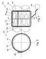
- Fig. 2 shows a cross-sectional view of the arrangement 100 along a line I-I' shown in Fig. 1.
- the arrangement 300 is used to connect a first electrical cable 301 to a second electrical cable 302.
- the first cable 301 comprises a copper core 301a and an insulation jacket 301 b, which envelops the copper core 301 a, for electrically insulating the copper core 301a.
- the second cable 302 comprises a copper core 302a and an insulation jacket 302b made from an electrically insulating material, which insulation jacket 302b envelops the copper core 302a.
- the first cable 301 and the second cable 302 are stripped of insulation.
- a Teflon shrink tube 303 has been pulled onto the stripped region of the first cable 301 and of the second cable 302.
- a heating mat 304 in other words a textile carrier material with a heating wire (not shown) provided therein, is provided which completely envelops the Teflon shrink tube.
- the heating wire of the heating mat 304 is connected to a circuit 108 by way of a cable 107.
- a defined quantity of thermal energy is supplied to the Teflon shrink tube 303 such that said Teflon shrink tube 303 shrinks, and produces a mechanical and electrical connection between the first wire 301 and the second wire 302. Since in the region stripped of the insulation the copper core 301a abuts the copper core 302a, the shrink tube 303, which tightly envelops the cables 301, 302, in the shrunk state establishes a mechanical and electrical connection.
- a device 400 for connecting two elements by means of shrinking a shrink tube according to one embodiment of the invention is described.
- the arrangement 400 again comprises a circuit 108 which is coupled to a heating element 404 by means of cables 107.
- the heating element 404 comprises a first semi-cylindrical heating element shell 401 and a second semi-cylindrical heating element shell 402, which are coupled by means of a hinge 403.
- the hinge 403 is closed such that complete enveloping of the heating element 404 by the shrink tube is possible.
- the heating element 404 comprises the robust solid body shells 401, 402 and a heating wire (the latter not shown in Fig. 4).
- a device 500 for connecting two elements by means of shrinking a shrink tube according to another embodiment of the invention is described.
- the device 500 comprises a circuit 108 which is electrically coupled to a heating wire 502 by way of cables 107.
- the heating wire 502 is embedded in a textile sleeve 501.
- a hook-tape closure 503 is provided in an end region of the textile sleeve 501 .
- the two elements are arranged so as to abut and are enveloped by a shrink tube. Then the sleeve 501 is wrapped around the shrink tube, wherein the textile sleeve 501 is fixed by means of the hook-tape closure 503.
- the circuit 108 provides electrical energy to the heating wire 502, wherein the heating wire 502 provides such an amount of energy to the shrink tube that said shrink tube shrinks and establishes a firm connection between the elements.
Landscapes
- Engineering & Computer Science (AREA)
- Mechanical Engineering (AREA)
- Physics & Mathematics (AREA)
- Thermal Sciences (AREA)
- Lining Or Joining Of Plastics Or The Like (AREA)
- Resistance Heating (AREA)
- Insulating Bodies (AREA)
- Protection Of Pipes Against Damage, Friction, And Corrosion (AREA)
- Laminated Bodies (AREA)
Abstract
Description
- Device for connecting two elements; arrangement for connecting two elements; method for producing a device for connecting two elements; method for connecting two elements; and the use of a heating element for shrinking a shrink tube.
- The invention relates to a device for connecting two elements, an arrangement for connecting two elements, a method for producing a device for connecting two elements, a method for connecting two elements, and the use of a heating element for shrinking a shrink tube.
- According to the state of the art, a shrink tube is used to establish a connection between two elements to be connected.
- The term "shrink tube" may relate in particular to a tube made from a thermoplastic material, which tube contracts due to the effect of heat. In other words, the diameter of the shrink tube is irreversibly reduced under the effect of heat such that the shrunk shrink tube engages the two elements to be connected and thus establishes a connection between the elements.
- According to the state of the art, in order to connect two elements with the use of a shrink tube, a shrink tube is pulled over a region of the abutting elements. Heat is applied to the shrink tube by means of an industrial hot-blast device or a Bunsen burner such that as a result of this the diameter of the shrink tube is reduced. The shrunk shrink tube thus contracts over the two ends of the elements and in this way forms a mechanical connection of the two elements.
- The use of shrink tubes for connecting elements to be connected plays a role in particular in aircraft because shrink tube connections contribute to keeping the weight of the aircraft down. Furthermore, installation and deinstallation effort is reduced (making four or at least two steel strip clamps dispensible). Moreover, keeping hitherto-used special couplers is no longer necessary for the manufacturer or for the operator.
- However, in an aircraft the available installation space is confined. Furthermore, an aircraft represents a temperature-sensitive environment in which the use of an open flame or some other strong heat source as used according to the state of the art for producing a shrink tube
-
US 5,053,595 andUS 4,883,925 disclose a connection system using heat shrink sleeves, wherein two cable elements can be connected via tubular heat schrink sleeves. The tubular sleeves are shrinkable when applying thermal energy. The thermal energy is applied inUS 5,053,595 by using a heatable wire that is wrapped around the shrink sleeve several times or by using a rigid heating element. connection is critical. Moreover, there are stringent safety regulations relating to aircraft; regulations which often are not compatible with the use of a Bunsen burner or an industrial hot-blast device. Such basic conditions can also be found in other environments (railways, office blocks, etc.) in which shrink tube connections can be used. - It is an object of the invention to provide a shrink tube connection for connecting two elements even in confined and temperature-sensitive environments.
- This object may be solved by a device for connecting two elements, by an arrangement for connecting two elements, by a method for producing a device for connecting two elements, by a method for connecting two elements, and by the use of a heating element for shrinking a shrink tube with the features according to the independent claims.
- The device according to the invention for connecting two elements by means of shrinking a shrink tube comprises a heating element and a control unit. The heating element is adapted for providing thermal or inductive energy and is further adapted such that with it a shrink tube, which can be pulled onto a connection region of two elements to be connected, can be encased along at least part of the circumference of the shrink tube. The control unit is adapted for supplying electrical energy to the heating element, and is further adapted such that with it the temperature of the heating element can be controlled in such a way that, by means of shrinking the shrink tube, the two elements are connectable.
- Furthermore, according to the invention, an arrangement is created for connecting a first element to a second element in a connection region by means of a shrink tube, wherein said arrangement comprises a first element, a second element, a shrink tube, a heating element and a control unit. The shrink tube is pullable onto a connection region of the first element and the second element. The heating element is adapted for providing thermal or inductive energy and is further adapted such that with it the shrink tube can be encased along at least part of the circumference of the shrink tube. The control unit is adapted for supplying electrical energy to the heating element and is further adapted such that with it the temperature of the heating element can be controlled such that, by means of shrinking the shrink tube, the first element can be connected to the second element.
- In the method according to the invention for producing a device for connecting two elements by means of shrinking a shrink tube, a heating element for providing thermal or inductive energy is formed and adapted such that with it a shrink tube which can be pulled onto a connection region of two elements to be connected can be encased along at least part of the circumference of the shrink tube. A control unit is formed for supplying electrical energy to the heating element and is adapted such that with it the temperature of the heating element can be controlled such that, by means of shrinking the shrink tube, the two elements are connectable.
- Furthermore, according to the invention, a method for connecting two elements by means of shrinking a shrink tube is provided, in which method a shrink tube is pulled onto a connection region of two elements to be connected, along at least part of its circumference the pulled-on shrink tube is encased by a heating element, and by means of the heating element thermal or inductive energy is supplied to the shrink tube, wherein the temperature of the heating element is controlled such that, by means of shrinking the shrink tube, the two elements are connected.
- According to the invention, furthermore, a shrink tube is used along at least part of the heating element encasing its circumference to provide thermal or inductive energy for shrinking the shrink tube for connecting two elements onto which in a connection region the shrink tube is pulled.
- A basic idea of the invention may be seen in that a shrink tube for connecting two elements is supplied in a targeted way with a defined quantity of heat required for shrinking, in that the shrink tube is directly encased by a heating element for providing the thermal or inductive energy required for shrinking. Preferably, the shrink tube is brought into direct contact with the heating element such that heat transfer/introduction can take place by means of heat conduction and/or heat radiation and/or heat convection. In other words, the heat source and the shrink tube are arranged so as to be directly spatially adjacent such that according to the invention the efficiency when supplying thermal or inductive energy for shrinking the shrink tube is significantly improved. Because the heat transfer is spatially more localised, and the quantity of heat to be provided overall is reduced as a result of increased efficiency during heat transfer when compared to the state of the art, the shrink tube connection according to the invention can be used even in critical, spatially confined, temperature-sensitive environments, for example in an aircraft. The solution according to the invention also meets stringent safety regulations because with the invention the quantity of heat emitted to the surroundings is reduced, and an open fire (as is the case with the use of a Bunsen burner) or a spatially non-confined flow of hot air (as is the case with the use of an industrial hot-blast device) is avoided.
- Application of the invention is therefore particularly advantageous in such scenarios in which due to confined installation space or stringent safety requirements (for example in an aircraft, in which a naked flame must at all costs be avoided, or in which the temperature sensitivity of the surroundings are to be taken into account) shrinking the shrink tube into place by means of an open heat source is problematic.
- Concretely, the heating element of the invention can be implemented as a heating sleeve for shrinking into place a shrink tube connection. In this way a secure lightweight connection between two elements can be implemented by means of a targeted supply of thermal or inductive energy, wherein the overall energy quantity arising and any undesired heating up of the environment are reduced.
- Two elements to be connected (for example two pipe ends to be connected or two cable ends to be connected), onto which elements the shrink tube is pulled, can be positioned such that the shrink tube is aligned by means of markings (for example colour markings) on the elements to be connected. A heating element (for example a heating mat) covers the shrink tube in a predefinable connection region, of sufficiently large size, of the elements to be connected. Preferably, the heating element envelops the shrink tube over its entire circumference. As an alternative it is possible that the heating element envelops the shrink tube only along part of its circumference (for example half the circumference or a quarter of the circumference), for example with the use of a heating element with an essentially U-shaped profile, into which the shrink tube can be inserted. Additional elements may be provided, for example a temperature sensor for determining the temperature of the heating element or of the shrink tube, or hook and fleece tapes for attaching a heating mat placed around the shrink tube.
- By means of a thermal energy source it is then possible to supply heat directly to the shrink tube, for example by implementing temperature control according to the specifications of the shrink tube or of a diameter parameter, if required with the use of time control, as a result of which the shrinking process is initiated and controlled or regulated. Once a desired shrinkage temperature has been achieved and this shrinkage temperature has been maintained for a specified period of time, the supply of energy can be terminated. A high-quality, secure and pressure-proof connection between the two elements (for example a pipe connection) has then been formed with little expenditure of energy. The heating sleeve can then be removed from the device and can be employed in some other position.
- The control unit, which is electrically coupled to the heating element, can control the time-related and/or space-related temperature gradient on the shrink tube. A control routing used to this purpose can be adapted specifically to the particular shrink tube used or to the particular elements to be connected that are used. The control modalities (for example control algorithm or regulating algorithm, materials parameter or diameter parameter) of the control unit can be predefined so as to be fixed in the control unit or they can be set by the user by means of a user interface on the control unit and can thus be adjusted flexibly to the requirements of each individual case.
- According to the invention, the control system can be implemented either by means of a computer program, i.e. by means of software, or by means of one or several special electronic circuits (for example on a printed circuit board or as a monolithically integrated circuit), i.e. in hardware, or in any desired hybrid form, i.e. by means of software components and hardware components, which algorithms take into account the materials characteristics of the shrink tube used, as well as its diameter. In this case a control unit is provided.
- Preferred improvements of the invention are stated in the dependent claims.
- Below, embodiments of the device according to the invention are described. These embodiments also apply to the arrangement according to the invention, to the methods according to the invention as well as to the use according to the invention.
- The device can comprise a carrier body on which and/or in which the heating element is arranged. The heating element can either be embedded in the carrier body or applied to the surface of said carrier body. Embedding provides safe protection of the heating element against damage because the heating element is surrounded by the material of the carrier body. Attachment of the heating element to the carrier body ensures particularly good heat transfer between the heating element and the shrink tube.
- The heating element and the carrier body can be a heating mat which is designed to be wrapped around the shrink tube. According to this embodiment, the heating mat can be mechanically flexible or bendable such that the heating mat can be wrapped around the shrink tube or around part of the shrink tube so as to establish good thermal contact. Concretely, such a heating mat or heating sleeve is an electrical heater, preferably comprising integrated thermal insulation. Such a heating sleeve can be made from a textile material and can comprise a heating surface, an electrically insulated heating line, thermal insulation and a robust outer casing. If such a heating sleeve is wrapped around a shrink tube, the heating sleeve can be fixed by means of an attachment device (for example a hook and loop fastener) such that the heating sleeve securely and steadily surrounds the shrink tube. Such an attachment device should be able to be detachable quickly such that after shrinking of the shrink tube the heating sleeve is removable and can be used immediately for establishing another shrink connection.
- According to the invention, the materials for such a heating sleeve can be selected based on the conditions of use (in particular the materials and geometric parameters of the shrink tube and the elements to be connected). For example silicon, textile glass or textile quartz glass can be used as materials for the carrier body.
- As an alternative to the described embodiment, the heating element and the carrier body can comprise two (or more) shell elements which are adapted to be placed around a shrink tube. For example, the heating element and the carrier body can comprise two semi-cylindrical shells, which are for example attached to each other by means of a hinge. The semi-cylindrical shells can be placed around the shrink tube and can subsequently be brought into direct contact with shrink tube, for example in that the hinge connection is closed. In this way particularly robust carrier bodies can be used. Furthermore, according to this embodiment, the installation effort for attachment of the device around a shrink tube to be shrunk is very modest.
- In the device, the heating element can be adapted such that with it a shrink tube that can be pulled onto a connection region of two elements to be connected can be encased along the entire circumference of the shrink tube. This embodiment provides particularly good heat exchange between the shrink tube and the heating element because the shrink tube is entirely surrounded by the thermal or inductive energy source, i.e. by the heating element.
- The heating element can for example be implemented as a meander-shaped heating wire. With this configuration a large quantity of heat can be provided in a confined space. A spiral-shaped geometry is also possible.
- The control unit/regulating unit can be designed such that it controls/regulates the temperature of the heating element based on at least one material parameter of a shrink tube to be shrunk. The required quantity of heat or an advantageous temperature gradient for the shrinking process of a shrink tube, among other things depends on the material. For example a radiation cross-linked polyolefin, Kynar™, Viton™ or Teflon™ can be used in a shrink tube.
- Furthermore, the control unit or regulating unit can be designed such that it controls and/or regulates the temperature of the heating element based on at least one geometry parameter of a shrink tube to be shrunk, for example its length, its diameter, or wall thickness. The quantity of heat to be supplied or an advantageous time-related temperature gradient on the heating element, among other things depends on the diameter of the shrink tube, its length, and on the elements (pipes, cables, wires, etc.) onto which it is to be shrunk. By means of adapting the temperature cycle, the shrinking-on process can be optimised.
- Furthermore, the control unit/regulating unit can be adapted in such a way that it controls/regulates a temperature-time gradient of the heating element. In this way a temperature cycle (heating - shrinking at a constant temperature - cooling) can in a targeted way be attuned to the materials used or to the elements to be connected.
- Preferably, the control unit is a regulating unit to which an actual temperature (i.e. a measured present temperature) of the heating element can be supplied and which, based on the actual temperature, regulates or sets a desired temperature of the heating element. In other words, the control unit according to the invention can also comprise a regulating mechanism. This means that the quantity of heat produced by the heating element is readjusted on the basis of an acquired actual temperature of the heating element. In this way the supply of too much or too little thermal or inductive energy to a shrink tube can be corrected.
- The device can comprise a temperature sensor for determining the actual temperature of the heating element, which temperature is to be supplied to the regulating unit. Such a temperature sensor can for example be a Pt100 resistance thermometer.
- Below, embodiments of the arrangement according to the invention are described. These embodiments also apply to the device according to the invention, the methods according to the invention, and to the use according to the invention.
- In the arrangement the first element can be a first pipe and the second element can be a second pipe. Thus, according to the invention, a high-quality pipe connection between two end regions of a pipe to be connected can be implemented with locally well-defined heat transfer.
- As an alternative, the first element can be a first cable (for example a wire with an insulation cover) and the second element can be a second cable (for example a wire with an insulation cover). It is thus for example possible to envelop two cable ends stripped of insulation, i.e. two bared wire ends, with a cylindrical shrink tube, and subsequently by means of targeted heat transfer to simultaneously interconnect the two wires mechanically and such that they are electrically conductive, and to provide electrical insulation to them. In this case the shrunk shrink tube is simultaneously a connection element and an electrical insulation element.
- Connection of the wires by means of the shrink tube can optionally, for example, be supported in that the wires in a border region comprise a means that strengthens the connection (for example a solder such as soldering tin). The heat transfer for shrinking the shrink tube can then also be used for melting the soldering tin.
- The first element can comprise a first alignment mark, and/or the second element can comprise a second alignment mark, wherein by means of the first alignment mark and/or the second alignment mark the shrink tube to be pulled on can be aligned on the first element and on the second element. Such an alignment mark on at least one of the two elements to be connected can be used for adapting the relative position of the first element in relation to the second element so as to achieve a high-quality good connection between the two elements.
- The first alignment mark and/or the second alignment mark can be a visually perceptible mark, a mark that is perceptible in a tactile sense, or a mechanical mark. A visual alignment mark can for example be a colour mark on the elements to be connected, for example a circumferential visible line provided on the first element and/or on the second element and which indicates optimum positioning of the two elements to be connected in that the two end regions of the shrink tube coincide with the colour marks with optimum positioning of the shrink tube pulled into place. The alignment mark can also be a scratch mark, in other words a mechanical indentation in one of the elements to be connected. An abutment mark is also possible, in other words a mechanical end stop for the pulled-on shrink tube on one of the elements to be connected.
- Below, one embodiment of the method for connecting two elements is described. This embodiment also applies to the device according to the invention, the arrangement according to the invention, the method according to the invention for producing the device, and to the use according to the invention.
- According to this embodiment, regulating (or controlling) the temperature of the heating element involves increasing the temperature from a starting temperature to a predefinable target temperature; maintaining the target temperature for a predefinable maintenance time; and reducing the temperature from the target temperature to the starting temperature. By predefining such a temperature cycle with predefinable parameters the shrinking process can be optimised. In this way a stable shrink tube connection is achieved with little heat transfer.
- Below, one embodiment of the use according to the invention is described. This embodiment also applies to the device according to the invention, the arrangement according to the invention, and the methods according to the invention.
- Shrinking shrink tubes by means of a defined supply of thermal or inductive energy to the shrink tube, with the use of a heating element enveloping said shrink tube for connecting two elements, can be carried out particularly advantageously in an aircraft. In an aircraft a shrink connection can be used as a reliable and weight-reducing connection between two elements, namely particularly advantageously when implementing such a shrink connection with the spatially exact supply, according to the invention, of thermal or inductive energy to a shrink tube to be shrunk, without there being any danger of overheating in a temperature-sensitive environment, or any danger of a fire breaking out.
- Embodiments of the invention are shown in the figures and are explained in further detail below.
- The following are shown:
- Figure 1
- a lateral view of an arrangement for connecting two pipes, according to a preferred embodiment of the invention;
- Figure 2
- a cross-sectional view, along sectional line I-I' shown in Figure 1, of the arrangement for connecting two pipes, according to the preferred embodiment of the invention;
- Figure 3
- a lateral view of an arrangement for connecting two cables, according to another embodiment of the invention;
- Figure 4
- a device for connecting two elements, according to one embodiment of the invention; and
- Figure 5
- a device for connecting two elements, according to another embodiment of the invention.
- Identical or similar components in various figures have identical reference numbers.
- The representations in the figures are schematically and not to scale.
- Furthermore, with reference to Figs 1 and 2, an
arrangement 100 for connecting afirst pipe 101 to asecond pipe 102 by means of shrinking apolyolefin shrink tube 103, according to a preferred embodiment of the invention is described. - As shown in Fig. 1, the
arrangement 100 comprises afirst pipe 101 and asecond pipe 102 which are to be connected in a connection region 111 (mechanically abutting or for mechanical end coupling <pipes can oscillate> with a gap). Thearrangement 100 further comprises apolyolefin shrink tube 103 which by way of theconnection region 111 of thefirst pipe 101 is connected to thesecond pipe 102. Furthermore, ameandering heating wire 104 with a high value of relative ohmic resistance is provided (on whichheating wire 104 thus an adequate quantity of ohmic heat can be released when an electric current flows through it). - The
heating wire 104 provides thermal energy for shrinking the polyolefin shrinktube 103 and is arranged such that with it the polyolefin shrinktube 103 is completely encased. Furthermore, asleeve 105, i.e. a bendable carrier material, is provided, with theheating wire 104 arranged on the inside of saidsleeve 105. Thesleeve 105 encases the polyolefin shrinktube 103 such that good thermal coupling, preferably direct thermal contact, i.e. mechanical contact, is established between theheating wire 104 and the polyolefin shrinktube 103. A hook-tape closure 106 ensures that an end region of thesleeve 105, which end region comprises a hook-tape closure 106, is firmly attachable to a central section of thesleeve 105, comprising a fleece tape. In other words, by overlapping the hook-tape closure 106 with a fleece tape, stable fixing of thesleeve 105 becomes possible. - Furthermore, Fig. 1 shows a
first colour mark 109 on thefirst pipe 101 and asecond colour mark 110 on thesecond pipe 102. When thepipes tube 103 covers theconnection region 111, then spatial correspondence of the colour marks 109, 110 with the marginal sections of the hollow cylindrical polyolefin shrinktube 103 or with thesleeve 105 indicates that the twosteel pipes - By means of a
cable 107, theheating wire 104 is electrically coupled to acontrol circuit 108. - The
control circuit 108 comprises a monolithically integrated circuit in which a control program for controlling or regulating the time gradient of the temperature on theheating wire 104 is stored. By means of a user interface, a user can enter parameters for a connection to be established (material and dimensions of the polyolefin shrinktube 103; material and dimensions of thepipes control circuit 108, controls and regulates the temperature gradient on theheating wire 104 in such a way that optimal shrinkage of the polyolefin shrinktube 103 becomes possible such that a permanent and stable connection between thefirst pipe 101 and thesecond pipe 102 is established. For this purpose thecircuit 108 provides electrical energy in a regulable quantity to theheating wire 104 by way of thecable 107, which electrical energy is convertible in the heating wire to ohmic or inductive heat and is thus convertible to thermal energy. Thecircuit 108 therefore also fulfils the function of an electrical energy source. - After a user has entered shrink connection parameters by means of a user interface, the
circuit 108, based on these shrink connection parameters, supplies electrical energy to theheating wire 104, which energy due to (desirable) ohmic losses in theheating wire 104 is converted to thermal energy. Due to good spatial and thermal coupling between theheating wire 104 and the polyolefin shrinktube 103 this thermal energy is transferred to saidshrink tube 103. As a result of this a defined quantity of heat is provided to the polyolefin shrinktube 103, which leads to shrinkage of theshrink tube 103. In this way a stable connection between thefirst pipe 101 and thesecond pipe 102 is established. - Fig. 2 shows a cross-sectional view of the
arrangement 100 along a line I-I' shown in Fig. 1. - Below, with reference to Fig. 3, an
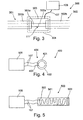
arrangement 300 according to another embodiment of the invention is described. - The
arrangement 300 is used to connect a firstelectrical cable 301 to a secondelectrical cable 302. As shown in Fig. 3, thefirst cable 301 comprises acopper core 301a and aninsulation jacket 301 b, which envelops thecopper core 301 a, for electrically insulating thecopper core 301a. Thesecond cable 302 comprises acopper core 302a and aninsulation jacket 302b made from an electrically insulating material, whichinsulation jacket 302b envelops thecopper core 302a. In aconnection region 111 to be established, thefirst cable 301 and thesecond cable 302 are stripped of insulation. In other words, in this abutting region theinsulation jacket 301b has been removed from thecopper core 301a, and theinsulation jacket 302b has been removed from thecopper core 302a. The twocables Teflon shrink tube 303 has been pulled onto the stripped region of thefirst cable 301 and of thesecond cable 302. Aheating mat 304, in other words a textile carrier material with a heating wire (not shown) provided therein, is provided which completely envelops the Teflon shrink tube. The heating wire of theheating mat 304 is connected to acircuit 108 by way of acable 107. - By way of providing electrical energy from the
circuit 108 to the heating wire of theheating mat 304, a defined quantity of thermal energy is supplied to the Teflon shrinktube 303 such that saidTeflon shrink tube 303 shrinks, and produces a mechanical and electrical connection between thefirst wire 301 and thesecond wire 302. Since in the region stripped of the insulation thecopper core 301a abuts thecopper core 302a, theshrink tube 303, which tightly envelops thecables - Below, with reference to Fig. 4 a
device 400 for connecting two elements by means of shrinking a shrink tube according to one embodiment of the invention is described. - The
arrangement 400 again comprises acircuit 108 which is coupled to aheating element 404 by means ofcables 107. Theheating element 404 comprises a first semi-cylindricalheating element shell 401 and a second semi-cylindrical heating element shell 402, which are coupled by means of ahinge 403. By opening thehinge 403, temporarily an opening can be established between the two semi-cylindricalheating element shells 401, 402, which opening is sufficient in size to insert a hollow-cylindrical shrink tube into theheating element 404. Then thehinge 403 is closed such that complete enveloping of theheating element 404 by the shrink tube is possible. Theheating element 404 comprises the robustsolid body shells 401, 402 and a heating wire (the latter not shown in Fig. 4). - Below, with reference to Fig. 5, a
device 500 for connecting two elements by means of shrinking a shrink tube according to another embodiment of the invention is described. - The
device 500 comprises acircuit 108 which is electrically coupled to aheating wire 502 by way ofcables 107. Theheating wire 502 is embedded in atextile sleeve 501. In an end region of the textile sleeve 501 a hook-tape closure 503 is provided. - To operate the
device 500 for connecting two elements, the two elements are arranged so as to abut and are enveloped by a shrink tube. Then thesleeve 501 is wrapped around the shrink tube, wherein thetextile sleeve 501 is fixed by means of the hook-tape closure 503. Thecircuit 108 provides electrical energy to theheating wire 502, wherein theheating wire 502 provides such an amount of energy to the shrink tube that said shrink tube shrinks and establishes a firm connection between the elements. -
- 100
- Arrangement
- 101
- First pipe
- 102
- Second pipe
- 103
- Polyolefin shrink tube
- 104
- Heating wire
- 105
- Sleeve
- 106
- Hook-tape closure
- 107
- Cable
- 108
- Circuit
- 109
- First colour mark
- 110
- Second colour mark
- 111
- Connection region
- 300
- Arrangement
- 301
- First cable
- 301a
- Copper core
- 301b
- Insulation jacket
- 302
- Second cable
- 302a
- Copper core
- 302b
- Insulation jacket
- 303
- Teflon shrink tube
- 304
- Heating mat
- 400
- Device
- 401
- First semi-cylindrical heating element shell
- 402
- Second semi-cylindrical heating element shell
- 403
- Hinge
- 404
- Heating element
- 500
- Device
- 501
- Textile sleeve
- 502
- Heating wire
- 503
- Hook-tape closure
Claims (18)
- A device for connecting two elements by means of shrinking a shrink tube (103; 303),• comprising a heating element (104, 404, 502);• comprising a control unit (108);• wherein the heating element (104, 404, 502) is adapted for providing thermal or inductive energy and is further adapted such that with it a shrink tube (103; 303), which is pullable onto a connection region of two elements (101, 102, 301, 302) to be connected, is encasable along at least a part of the circumference of the shrink tube (103; 303); and• wherein the control unit (108) is adapted for supplying electrical energy to the heating element (104, 404, 502) and furthermore is adapted such that with it the temperature of the heating element (104, 404, 502) is controllable in such a manner that, by means of shrinking the shrink tube (103; 303), the two elements (101, 102, 301, 302) are connectable;• wherein the device (100, 300, 400, 500) further comprises a bendable carrier body (105, 304, 501) on and/or in which the heating element (104, 404, 502) is arranged;• wherein the heating element (104, 404, 502) and the carrier body (105, 304, 501)are adapted for being flexibly wrapped around a shrink tube (103; 303).
- The device of claim 1,
in which the heating element (104, 404, 502) is adapted such that with it a shrink tube(103; 303), which is pullable onto a connection region of two elements (101, 102, 301, 302)to be connected, is encasable along the entire circumference of the shrink tube (103; 303). - The device of any one of claims 1 to 2,
in which the heating element (104, 404, 502) is a meander-shaped heating wire. - The device of any one of claims 1 to 3,
in which the control unit (108) is adapted such that it controls the temperature of the heating element (104, 404, 502) based on at least one material parameter of a shrink tube (103; 303) to be shrunk. - The device of any one of claims 1 to 4,
in which the control unit (108) is adapted such that it controls the temperature of the heating element (104, 404, 502) based on at least one geometry parameter of a shrink tube (103; 303) to be shrunk. - The device of any one of claims 1 to 5,
in which the control unit (108) is adapted such that it controls a predefinable temperature-time characteristics of the heating element (104, 404, 502). - The device of any one of claims 1 to 6,
in which the control unit (108) is a regulating unit to which an actual temperature of the heating element (104, 404, 502) is supplyable, and which, based on the actual temperature, controls a desired temperature of the heating element (104, 404, 502). - The device of claim 7,
comprising a temperature sensor for determining the actual temperature of the heating element (104, 404, 502), which actual temperature is supplyable to the regulating unit. - An arrangement for connecting a first element to a second element in a connection region by means of a (103; 303) shrink tube,
comprising a first element;
comprising a second element;
comprising a shrink tube (103; 303);
comprising a device (100, 300, 400, 500) of any of claims 1 to 8 for connecting the first element to the second element by means of shrinking the shrink tube (103; 303);
wherein the shrink tube is pullable onto a connection region of the first element with the second element; - The arrangement of claim 9,
in which the first element is a first pipe, and in which the second element is a second pipe. - The arrangement of claim 9,
in which the first element is a first cable, and in which the second element is a second cable. - The arrangement of any one of claims 9 to 11,
in which the first element comprises a first alignment mark and/or in which the second element comprises a second alignment mark, wherein by means of the first alignment mark and/or the second alignment mark the shrink tube (103; 303) to be pulled on is alignable on the first element and on the second element. - The arrangement of claim 12,
in which the first alignment mark and/or the second alignment mark is• a visually perceptible mark;• a mark that is perceptible in a tactile sense; or• a mechanical mark. - A method for producing a device according to one of the claims 1 to 8 for connecting two elements (101, 102, 301, 302) by means of shrinking a shrink tube (103; 303),
in which• a heating element (104, 404, 502) is adapted for providing thermal or inductive energy and is further adapted such that with it a shrink tube, which is pullable onto a connection region of two elements (101, 102, 301, 302) to be connected, is encasable along at least a part of a circumference of the shrink tube (103; 303) and wherein the heating element (104, 404, 502) and the bendable carrier body (105, 304, 501) are adapted for being flexibly wrapped around a shrink tube (103; 303); and• a control unit (108) is formed for supplying electrical energy to the heating element (104, 404, 502) and is adapted such that with it the temperature of the heating element (104, 404, 502) is controllable in such a manner that, by means of shrinking the shrink tube (103; 303), the two elements (101, 102, 301, 302) are connectable. - A method for connecting two elements (101, 102, 301, 302) by means of a device according to one of the claims 1 to 8,
in which• a shrink tube (103; 303) is pulled onto a connection region of two elements (101, 102, 301, 302) to be connected;• the pulled-on shrink tube (103; 303) is encased by a heating element (104, 404, 502) along at least a part of its circumference; wherein the heating element (104, 404, 502) and a bendable carrier body (105, 304, 501) are adapted for being flexibly wrapped around a shrink tube (103; 303); and• by means of the heating element (104, 404, 502) thermal or inductive energy is supplied to the shrink tube (103; 303), wherein the temperature of the heating element (104, 404, 502) is controlled in such a manner that the two elements (101, 102, 301, 302) are connected by means of shrinking the shrink tube (103; 303); - The method of claim 15,
in which controlling the temperature of the heating element (104, 404, 502) comprises• increasing the temperature from a starting temperature to a predefinable target temperature;• maintaining the target temperature for a predefinable maintenance time; and• reducing the temperature from the target temperature to the starting temperature. - The use of a device according to one of the claims 1 to 8, wherein a heating element (104, 404, 502)encases a shrink tube (103; 303) along at least part of its circumference for providing thermal or inductive energy for shrinking the shrink tube (103; 303) for connecting two elements (101, 102, 301, 302) in a connection region on which the shrink tube (103; 303) is pulled.
- The use of claim 17,
implemented in an aircraft.
Applications Claiming Priority (2)
| Application Number | Priority Date | Filing Date | Title |
|---|---|---|---|
| US60005504P | 2004-08-09 | 2004-08-09 | |
| DE102004038629A DE102004038629A1 (en) | 2004-08-09 | 2004-08-09 | Pipe connecting arrangement for use in e.g. aircraft, has heating unit embedded in carrier body, and heating wire providing thermal or inductive energy, where temperature of wire is controlled by shrinking shrink tube |
Publications (2)
| Publication Number | Publication Date |
|---|---|
| EP1628362A1 EP1628362A1 (en) | 2006-02-22 |
| EP1628362B1 true EP1628362B1 (en) | 2007-10-31 |
Family
ID=35058438
Family Applications (1)
| Application Number | Title | Priority Date | Filing Date |
|---|---|---|---|
| EP20050017290 Expired - Lifetime EP1628362B1 (en) | 2004-08-09 | 2005-08-09 | Heating sleeve for shrinking on of shrink tube connections |
Country Status (3)
| Country | Link |
|---|---|
| EP (1) | EP1628362B1 (en) |
| AT (1) | ATE377269T1 (en) |
| DE (1) | DE602005003073T2 (en) |
Families Citing this family (4)
| Publication number | Priority date | Publication date | Assignee | Title |
|---|---|---|---|---|
| BRPI0823105B1 (en) * | 2007-11-30 | 2020-11-17 | Aktiebolaget Skf | method for heating a bearing element bearing |
| DE102008025085A1 (en) * | 2008-05-26 | 2009-12-03 | Pirtek (Deutschland) Gmbh | Fluid hose for promotion of liquids or gases, has conduit, connected hose fitting for connection of fluid hose with device, and information element with visible optical coding |
| LT2987624T (en) * | 2014-08-21 | 2019-03-12 | Frans Nooren Afdichtingssystemen B.V. | Heating blanket |
| DE102023106306A1 (en) * | 2023-03-14 | 2024-09-19 | Deutsches Zentrum für Luft- und Raumfahrt e.V. | Electric resistance welding element and method for producing an electric resistance welding element |
Family Cites Families (2)
| Publication number | Priority date | Publication date | Assignee | Title |
|---|---|---|---|---|
| US5053595A (en) * | 1982-12-01 | 1991-10-01 | Metcal, Inc. | Heat shrink sleeve with high mu material |
| US4883925A (en) * | 1988-05-02 | 1989-11-28 | Graf Albert C | Sealed solder connector assembly and method of use |
-
2005
- 2005-08-09 AT AT05017290T patent/ATE377269T1/en not_active IP Right Cessation
- 2005-08-09 DE DE200560003073 patent/DE602005003073T2/en not_active Expired - Lifetime
- 2005-08-09 EP EP20050017290 patent/EP1628362B1/en not_active Expired - Lifetime
Also Published As
| Publication number | Publication date |
|---|---|
| EP1628362A1 (en) | 2006-02-22 |
| DE602005003073D1 (en) | 2007-12-13 |
| ATE377269T1 (en) | 2007-11-15 |
| DE602005003073T2 (en) | 2008-08-14 |
Similar Documents
| Publication | Publication Date | Title |
|---|---|---|
| US20060027536A1 (en) | Heating sleeve for shrinking on of shrink tube connections | |
| US5167545A (en) | Connector containing fusible material and having intrinsic temperature control | |
| KR100732782B1 (en) | Method of manufacturing soldering iron and soldering iron | |
| JP2673728B2 (en) | Electric terminal and method of manufacturing electric connector using the same | |
| JPH0375262B2 (en) | ||
| NL1023128C2 (en) | Cable sleeve. | |
| WO1997023924A1 (en) | Electrical connector | |
| JP2724623B2 (en) | Connector termination device and method | |
| EP1628362B1 (en) | Heating sleeve for shrinking on of shrink tube connections | |
| EP1204891B1 (en) | A device for heating shrinkable sleeves | |
| EP0554375B1 (en) | Self-regulating connecting device containing fusible material | |
| CA2547151C (en) | Method for the attachment of an electrical lead wire on a surface element, as well as a heating element, especially for a plastic-spraying device | |
| JPH0461575B2 (en) | ||
| CN114914855B (en) | Method for installing heat shrink cover, electric heating system and installation system | |
| KR20160007504A (en) | Method for producing a heating cable and heating cable produced according to this method | |
| EP3065932B1 (en) | Method for connecting plastic pipes and structure for connecting the same | |
| EP3574709B1 (en) | Devices for heating small-diameter tubing and methods of making and using | |
| EP0371455B1 (en) | Method of joining a plurality of associated pairs of electrical conductors | |
| US10525624B2 (en) | Heating element for a flow channel or a mould impression and injection-moulding nozzle with such a heating element | |
| GB2399680A (en) | Thermocouple for electro valves of gas burners | |
| CN216357366U (en) | Heater for semiconductor equipment | |
| JP3783272B2 (en) | Manufacturing method of thermal fuse | |
| JP3430370B2 (en) | Heater device | |
| JP3004043U (en) | Molten metal heating device | |
| CA3150126A1 (en) | Cable heating apparatus and method |
Legal Events
| Date | Code | Title | Description |
|---|---|---|---|
| REG | Reference to a national code |
Ref country code: SE Ref legal event code: TRGR |
|
| PUAI | Public reference made under article 153(3) epc to a published international application that has entered the european phase |
Free format text: ORIGINAL CODE: 0009012 |
|
| AK | Designated contracting states |
Kind code of ref document: A1 Designated state(s): AT BE BG CH CY CZ DE DK EE ES FI FR GB GR HU IE IS IT LI LT LU LV MC NL PL PT RO SE SI SK TR |
|
| AX | Request for extension of the european patent |
Extension state: AL BA HR MK YU |
|
| 17P | Request for examination filed |
Effective date: 20060817 |
|
| AKX | Designation fees paid |
Designated state(s): AT BE BG CH CY CZ DE DK EE ES FI FR GB GR HU IE IS IT LI LT LU LV MC NL PL PT RO SE SI SK TR |
|
| 17Q | First examination report despatched |
Effective date: 20061016 |
|
| GRAP | Despatch of communication of intention to grant a patent |
Free format text: ORIGINAL CODE: EPIDOSNIGR1 |
|
| GRAS | Grant fee paid |
Free format text: ORIGINAL CODE: EPIDOSNIGR3 |
|
| GRAA | (expected) grant |
Free format text: ORIGINAL CODE: 0009210 |
|
| AK | Designated contracting states |
Kind code of ref document: B1 Designated state(s): AT BE BG CH CY CZ DE DK EE ES FI FR GB GR HU IE IS IT LI LT LU LV MC NL PL PT RO SE SI SK TR |
|
| REG | Reference to a national code |
Ref country code: GB Ref legal event code: FG4D |
|
| REG | Reference to a national code |
Ref country code: IE Ref legal event code: FG4D |
|
| REG | Reference to a national code |
Ref country code: CH Ref legal event code: EP |
|
| REF | Corresponds to: |
Ref document number: 602005003073 Country of ref document: DE Date of ref document: 20071213 Kind code of ref document: P |
|
| NLV1 | Nl: lapsed or annulled due to failure to fulfill the requirements of art. 29p and 29m of the patents act | ||
| PG25 | Lapsed in a contracting state [announced via postgrant information from national office to epo] |
Ref country code: NL Free format text: LAPSE BECAUSE OF FAILURE TO SUBMIT A TRANSLATION OF THE DESCRIPTION OR TO PAY THE FEE WITHIN THE PRESCRIBED TIME-LIMIT Effective date: 20071031 Ref country code: CH Free format text: LAPSE BECAUSE OF FAILURE TO SUBMIT A TRANSLATION OF THE DESCRIPTION OR TO PAY THE FEE WITHIN THE PRESCRIBED TIME-LIMIT Effective date: 20071031 Ref country code: LI Free format text: LAPSE BECAUSE OF FAILURE TO SUBMIT A TRANSLATION OF THE DESCRIPTION OR TO PAY THE FEE WITHIN THE PRESCRIBED TIME-LIMIT Effective date: 20071031 Ref country code: ES Free format text: LAPSE BECAUSE OF FAILURE TO SUBMIT A TRANSLATION OF THE DESCRIPTION OR TO PAY THE FEE WITHIN THE PRESCRIBED TIME-LIMIT Effective date: 20080211 |
|
| REG | Reference to a national code |
Ref country code: CH Ref legal event code: PL |
|
| PG25 | Lapsed in a contracting state [announced via postgrant information from national office to epo] |
Ref country code: PL Free format text: LAPSE BECAUSE OF FAILURE TO SUBMIT A TRANSLATION OF THE DESCRIPTION OR TO PAY THE FEE WITHIN THE PRESCRIBED TIME-LIMIT Effective date: 20071031 Ref country code: LT Free format text: LAPSE BECAUSE OF FAILURE TO SUBMIT A TRANSLATION OF THE DESCRIPTION OR TO PAY THE FEE WITHIN THE PRESCRIBED TIME-LIMIT Effective date: 20071031 Ref country code: SI Free format text: LAPSE BECAUSE OF FAILURE TO SUBMIT A TRANSLATION OF THE DESCRIPTION OR TO PAY THE FEE WITHIN THE PRESCRIBED TIME-LIMIT Effective date: 20071031 Ref country code: LV Free format text: LAPSE BECAUSE OF FAILURE TO SUBMIT A TRANSLATION OF THE DESCRIPTION OR TO PAY THE FEE WITHIN THE PRESCRIBED TIME-LIMIT Effective date: 20071031 Ref country code: PT Free format text: LAPSE BECAUSE OF FAILURE TO SUBMIT A TRANSLATION OF THE DESCRIPTION OR TO PAY THE FEE WITHIN THE PRESCRIBED TIME-LIMIT Effective date: 20080331 Ref country code: IS Free format text: LAPSE BECAUSE OF FAILURE TO SUBMIT A TRANSLATION OF THE DESCRIPTION OR TO PAY THE FEE WITHIN THE PRESCRIBED TIME-LIMIT Effective date: 20080229 Ref country code: BG Free format text: LAPSE BECAUSE OF FAILURE TO SUBMIT A TRANSLATION OF THE DESCRIPTION OR TO PAY THE FEE WITHIN THE PRESCRIBED TIME-LIMIT Effective date: 20080131 |
|
| PG25 | Lapsed in a contracting state [announced via postgrant information from national office to epo] |
Ref country code: AT Free format text: LAPSE BECAUSE OF FAILURE TO SUBMIT A TRANSLATION OF THE DESCRIPTION OR TO PAY THE FEE WITHIN THE PRESCRIBED TIME-LIMIT Effective date: 20071031 |
|
| ET | Fr: translation filed | ||
| PG25 | Lapsed in a contracting state [announced via postgrant information from national office to epo] |
Ref country code: DK Free format text: LAPSE BECAUSE OF FAILURE TO SUBMIT A TRANSLATION OF THE DESCRIPTION OR TO PAY THE FEE WITHIN THE PRESCRIBED TIME-LIMIT Effective date: 20071031 Ref country code: CZ Free format text: LAPSE BECAUSE OF FAILURE TO SUBMIT A TRANSLATION OF THE DESCRIPTION OR TO PAY THE FEE WITHIN THE PRESCRIBED TIME-LIMIT Effective date: 20071031 |
|
| PG25 | Lapsed in a contracting state [announced via postgrant information from national office to epo] |
Ref country code: RO Free format text: LAPSE BECAUSE OF FAILURE TO SUBMIT A TRANSLATION OF THE DESCRIPTION OR TO PAY THE FEE WITHIN THE PRESCRIBED TIME-LIMIT Effective date: 20071031 Ref country code: BE Free format text: LAPSE BECAUSE OF FAILURE TO SUBMIT A TRANSLATION OF THE DESCRIPTION OR TO PAY THE FEE WITHIN THE PRESCRIBED TIME-LIMIT Effective date: 20071031 Ref country code: SK Free format text: LAPSE BECAUSE OF FAILURE TO SUBMIT A TRANSLATION OF THE DESCRIPTION OR TO PAY THE FEE WITHIN THE PRESCRIBED TIME-LIMIT Effective date: 20071031 |
|
| PLBE | No opposition filed within time limit |
Free format text: ORIGINAL CODE: 0009261 |
|
| STAA | Information on the status of an ep patent application or granted ep patent |
Free format text: STATUS: NO OPPOSITION FILED WITHIN TIME LIMIT |
|
| 26N | No opposition filed |
Effective date: 20080801 |
|
| PG25 | Lapsed in a contracting state [announced via postgrant information from national office to epo] |
Ref country code: GR Free format text: LAPSE BECAUSE OF FAILURE TO SUBMIT A TRANSLATION OF THE DESCRIPTION OR TO PAY THE FEE WITHIN THE PRESCRIBED TIME-LIMIT Effective date: 20080201 |
|
| PG25 | Lapsed in a contracting state [announced via postgrant information from national office to epo] |
Ref country code: FI Free format text: LAPSE BECAUSE OF FAILURE TO SUBMIT A TRANSLATION OF THE DESCRIPTION OR TO PAY THE FEE WITHIN THE PRESCRIBED TIME-LIMIT Effective date: 20071031 |
|
| PG25 | Lapsed in a contracting state [announced via postgrant information from national office to epo] |
Ref country code: MC Free format text: LAPSE BECAUSE OF NON-PAYMENT OF DUE FEES Effective date: 20080831 |
|
| PG25 | Lapsed in a contracting state [announced via postgrant information from national office to epo] |
Ref country code: EE Free format text: LAPSE BECAUSE OF FAILURE TO SUBMIT A TRANSLATION OF THE DESCRIPTION OR TO PAY THE FEE WITHIN THE PRESCRIBED TIME-LIMIT Effective date: 20071031 |
|
| PG25 | Lapsed in a contracting state [announced via postgrant information from national office to epo] |
Ref country code: CY Free format text: LAPSE BECAUSE OF FAILURE TO SUBMIT A TRANSLATION OF THE DESCRIPTION OR TO PAY THE FEE WITHIN THE PRESCRIBED TIME-LIMIT Effective date: 20071031 Ref country code: IE Free format text: LAPSE BECAUSE OF NON-PAYMENT OF DUE FEES Effective date: 20080811 |
|
| PG25 | Lapsed in a contracting state [announced via postgrant information from national office to epo] |
Ref country code: HU Free format text: LAPSE BECAUSE OF FAILURE TO SUBMIT A TRANSLATION OF THE DESCRIPTION OR TO PAY THE FEE WITHIN THE PRESCRIBED TIME-LIMIT Effective date: 20080501 Ref country code: LU Free format text: LAPSE BECAUSE OF NON-PAYMENT OF DUE FEES Effective date: 20080809 |
|
| PG25 | Lapsed in a contracting state [announced via postgrant information from national office to epo] |
Ref country code: TR Free format text: LAPSE BECAUSE OF FAILURE TO SUBMIT A TRANSLATION OF THE DESCRIPTION OR TO PAY THE FEE WITHIN THE PRESCRIBED TIME-LIMIT Effective date: 20071031 |
|
| REG | Reference to a national code |
Ref country code: FR Ref legal event code: CD Owner name: AIRBUS OPERATIONS GMBH Effective date: 20111118 |
|
| REG | Reference to a national code |
Ref country code: DE Ref legal event code: R082 Ref document number: 602005003073 Country of ref document: DE Representative=s name: LKGLOBAL | LORENZ & KOPF PARTG MBB PATENTANWAE, DE Ref country code: DE Ref legal event code: R082 Ref document number: 602005003073 Country of ref document: DE Representative=s name: KOPF WESTENBERGER WACHENHAUSEN PATENTANWAELTE , DE |
|
| REG | Reference to a national code |
Ref country code: FR Ref legal event code: PLFP Year of fee payment: 12 |
|
| PGFP | Annual fee paid to national office [announced via postgrant information from national office to epo] |
Ref country code: DE Payment date: 20160822 Year of fee payment: 12 Ref country code: GB Payment date: 20160819 Year of fee payment: 12 Ref country code: IT Payment date: 20160825 Year of fee payment: 12 |
|
| PGFP | Annual fee paid to national office [announced via postgrant information from national office to epo] |
Ref country code: FR Payment date: 20160822 Year of fee payment: 12 Ref country code: SE Payment date: 20160819 Year of fee payment: 12 |
|
| REG | Reference to a national code |
Ref country code: DE Ref legal event code: R119 Ref document number: 602005003073 Country of ref document: DE |
|
| GBPC | Gb: european patent ceased through non-payment of renewal fee |
Effective date: 20170809 |
|
| PG25 | Lapsed in a contracting state [announced via postgrant information from national office to epo] |
Ref country code: SE Free format text: LAPSE BECAUSE OF NON-PAYMENT OF DUE FEES Effective date: 20170810 |
|
| REG | Reference to a national code |
Ref country code: FR Ref legal event code: ST Effective date: 20180430 |
|
| PG25 | Lapsed in a contracting state [announced via postgrant information from national office to epo] |
Ref country code: DE Free format text: LAPSE BECAUSE OF NON-PAYMENT OF DUE FEES Effective date: 20180301 Ref country code: GB Free format text: LAPSE BECAUSE OF NON-PAYMENT OF DUE FEES Effective date: 20170809 |
|
| PG25 | Lapsed in a contracting state [announced via postgrant information from national office to epo] |
Ref country code: IT Free format text: LAPSE BECAUSE OF NON-PAYMENT OF DUE FEES Effective date: 20170809 Ref country code: FR Free format text: LAPSE BECAUSE OF NON-PAYMENT OF DUE FEES Effective date: 20170831 |