EP1628072A2 - Outgassing shield for lamp socket - Google Patents
Outgassing shield for lamp socket Download PDFInfo
- Publication number
- EP1628072A2 EP1628072A2 EP05015664A EP05015664A EP1628072A2 EP 1628072 A2 EP1628072 A2 EP 1628072A2 EP 05015664 A EP05015664 A EP 05015664A EP 05015664 A EP05015664 A EP 05015664A EP 1628072 A2 EP1628072 A2 EP 1628072A2
- Authority
- EP
- European Patent Office
- Prior art keywords
- socket
- lamp
- shield
- outgassing
- lamp socket
- Prior art date
- Legal status (The legal status is an assumption and is not a legal conclusion. Google has not performed a legal analysis and makes no representation as to the accuracy of the status listed.)
- Granted
Links
- 238000010943 off-gassing Methods 0.000 title claims abstract description 19
- 239000000463 material Substances 0.000 claims abstract description 14
- 239000004033 plastic Substances 0.000 claims description 2
- 239000002184 metal Substances 0.000 claims 1
- 229910001220 stainless steel Inorganic materials 0.000 claims 1
- 239000010935 stainless steel Substances 0.000 claims 1
- 230000002939 deleterious effect Effects 0.000 abstract 1
- 230000008030 elimination Effects 0.000 abstract 1
- 238000003379 elimination reaction Methods 0.000 abstract 1
- 230000002708 enhancing effect Effects 0.000 abstract 1
- 239000004677 Nylon Substances 0.000 description 2
- 230000002411 adverse Effects 0.000 description 2
- 230000008021 deposition Effects 0.000 description 2
- 239000007789 gas Substances 0.000 description 2
- 239000011521 glass Substances 0.000 description 2
- 229920001778 nylon Polymers 0.000 description 2
- 239000010965 430 stainless steel Substances 0.000 description 1
- 230000036760 body temperature Effects 0.000 description 1
- 239000003292 glue Substances 0.000 description 1
- 230000002401 inhibitory effect Effects 0.000 description 1
- 238000003780 insertion Methods 0.000 description 1
- 230000037431 insertion Effects 0.000 description 1
- 238000009434 installation Methods 0.000 description 1
- 238000012986 modification Methods 0.000 description 1
- 230000004048 modification Effects 0.000 description 1
- 229920003031 santoprene Polymers 0.000 description 1
Images

Classifications
-
- F—MECHANICAL ENGINEERING; LIGHTING; HEATING; WEAPONS; BLASTING
- F21—LIGHTING
- F21S—NON-PORTABLE LIGHTING DEVICES; SYSTEMS THEREOF; VEHICLE LIGHTING DEVICES SPECIALLY ADAPTED FOR VEHICLE EXTERIORS
- F21S45/00—Arrangements within vehicle lighting devices specially adapted for vehicle exteriors, for purposes other than emission or distribution of light
- F21S45/40—Cooling of lighting devices
-
- F—MECHANICAL ENGINEERING; LIGHTING; HEATING; WEAPONS; BLASTING
- F21—LIGHTING
- F21S—NON-PORTABLE LIGHTING DEVICES; SYSTEMS THEREOF; VEHICLE LIGHTING DEVICES SPECIALLY ADAPTED FOR VEHICLE EXTERIORS
- F21S41/00—Illuminating devices specially adapted for vehicle exteriors, e.g. headlamps
- F21S41/10—Illuminating devices specially adapted for vehicle exteriors, e.g. headlamps characterised by the light source
- F21S41/19—Attachment of light sources or lamp holders
-
- F—MECHANICAL ENGINEERING; LIGHTING; HEATING; WEAPONS; BLASTING
- F21—LIGHTING
- F21S—NON-PORTABLE LIGHTING DEVICES; SYSTEMS THEREOF; VEHICLE LIGHTING DEVICES SPECIALLY ADAPTED FOR VEHICLE EXTERIORS
- F21S43/00—Signalling devices specially adapted for vehicle exteriors, e.g. brake lamps, direction indicator lights or reversing lights
- F21S43/10—Signalling devices specially adapted for vehicle exteriors, e.g. brake lamps, direction indicator lights or reversing lights characterised by the light source
- F21S43/19—Attachment of light sources or lamp holders
-
- F—MECHANICAL ENGINEERING; LIGHTING; HEATING; WEAPONS; BLASTING
- F21—LIGHTING
- F21S—NON-PORTABLE LIGHTING DEVICES; SYSTEMS THEREOF; VEHICLE LIGHTING DEVICES SPECIALLY ADAPTED FOR VEHICLE EXTERIORS
- F21S45/00—Arrangements within vehicle lighting devices specially adapted for vehicle exteriors, for purposes other than emission or distribution of light
- F21S45/10—Protection of lighting devices
-
- F—MECHANICAL ENGINEERING; LIGHTING; HEATING; WEAPONS; BLASTING
- F21—LIGHTING
- F21S—NON-PORTABLE LIGHTING DEVICES; SYSTEMS THEREOF; VEHICLE LIGHTING DEVICES SPECIALLY ADAPTED FOR VEHICLE EXTERIORS
- F21S43/00—Signalling devices specially adapted for vehicle exteriors, e.g. brake lamps, direction indicator lights or reversing lights
- F21S43/10—Signalling devices specially adapted for vehicle exteriors, e.g. brake lamps, direction indicator lights or reversing lights characterised by the light source
- F21S43/19—Attachment of light sources or lamp holders
- F21S43/195—Details of lamp holders, terminals or connectors
-
- H—ELECTRICITY
- H01—ELECTRIC ELEMENTS
- H01R—ELECTRICALLY-CONDUCTIVE CONNECTIONS; STRUCTURAL ASSOCIATIONS OF A PLURALITY OF MUTUALLY-INSULATED ELECTRICAL CONNECTING ELEMENTS; COUPLING DEVICES; CURRENT COLLECTORS
- H01R33/00—Coupling devices specially adapted for supporting apparatus and having one part acting as a holder providing support and electrical connection via a counterpart which is structurally associated with the apparatus, e.g. lamp holders; Separate parts thereof
- H01R33/05—Two-pole devices
- H01R33/06—Two-pole devices with two current-carrying pins, blades or analogous contacts, having their axes parallel to each other
- H01R33/09—Two-pole devices with two current-carrying pins, blades or analogous contacts, having their axes parallel to each other for baseless lamp bulb
Definitions
- This invention relates to lamp sockets and more particularly to lamp sockets for an automotive application. Still more particularly, it relates to a lamp socket having a reduced tendency to outgas products that can deposit on the reflector and lens of a lamp body thereby reducing the efficiency of the lamp.
- this invention is particularly applicable to automotive sockets employed in taillights and turn signal lights.
- Such sockets are shown, for example, in U.S. Patent nos. 5,411,407 and 5,971,814, both assigned to the assignee of the present invention.
- Such sockets can be constructed of nylon with a 43% glass fill and are usually designated as S8 sockets that take S8 bulbs.
- the S8 bulb has a wedge base that frictionally engages contacts within the socket and these bulbs can operate at temperatures above 100°C. At such temperatures entrained gases can be out-gassed from the socket material and deposit upon the lamp envelope adversely affecting the lamp's performance.
- the socket has a socket body extending from a base, with the socket body being adapted to be inserted into a lamp body and the out-gassing shield being positioned on a part of the socket body that is positioned within the lamp body.
- the shield maintains a lower temperature upon the socket and prevents or severely limits the amount of outgassing that can occur.
- Fig. 1 is a diagrammatic elevational sectional view of a lamp employing the invention
- Fig. 2 is a perspective view of a lamp socket with which the invention can be used'
- Fig. 3 is a plan view of the outgassing shield of the invention.
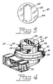
- Fig. 4 is perspective view of a lamp socket with the outgassing shield in place.
- a lamp 10 having a body 12 comprised of a cavity 14 and a lens 16.
- the inner surface 17 of the cavity 14 has a reflective finish thereon.
- a lamp unit 18 comprising a lamp 20 mounted in a socket body 22 is fitted into the base 24 of the lamp body, as is conventional.
- the socket body 22 is disposed about a longitudinal axis 26.
- the socket body is composed of a material, such as nylon with a 43% glass filling, that is subject to outgassing with elevated temperatures. While the use of higher temperature materials to prevent outgassing would be an option, it is not really a solution since the higher cost would be a negative factor.
- the body 22 has an opening 28 containing a plurality of electrical contacts and a reception area for the bulb 20.
- the body 22 further has a gasket reception area 30 surrounding the body 22 for receiving a gasket 32.
- the gasket 32 will be a pre-molded Santoprene gasket, which will stretch to fit over the conventional lamp socket threads 34 such that the gasket will bear against the reflector base 24 when the lamp socket is positioned for use.
- the gasket reception area 30 has an overhang 36 to aid in the installation of the lamp socket in the reflector.
- a shroud 38 projects from the socket body 22 and contains the electrical terminals for connection to a power source.
- an outgassing shield 40 that is substantially cup-shaped with a surface 42 and a circumferential sidewall 44. An opening 44 is provided in the surface 42 to allow insertion of the bulb 20.
- the shield 40 covers substantially all of the plastic components of the socket body that project within the lamp body 12 and creates a lower temperature zone when the lamp 20 is operating, thereby reducing the amount of outgassing and the consequent deposition of undesirable quantities of material upon the reflector surface 17 and the interior of the lens 19.
- the surface 42 substantially matches the reflectance characteristics of the reflector surface 17. With the shield installed the socket body is not apparent to a viewer when the lamp is not operating, thus contributing to the aesthetic appeal of the lamp. Further, it is possible under certain conditions that the light output of the lamp can be increased.
- the shield 40 is fitted over the interior portion of the socket body 22 and can be held in place frictionally or by other means, such as glue or pins.
- shield 40 While numerous materials are suitable for the shield 40, a preferred material is 430 stainless steel having a thickness of 0.4 mm.
- Tests run on sockets with and without the shield show a 23° C reduction in upper body temperature with the shield in place, thus effectively inhibiting outgassing and the subsequent unwanted deposition of extraneous material on the reflector and lens of the lamp assembly.
Landscapes
- Engineering & Computer Science (AREA)
- General Engineering & Computer Science (AREA)
- Non-Portable Lighting Devices Or Systems Thereof (AREA)
- Arrangement Of Elements, Cooling, Sealing, Or The Like Of Lighting Devices (AREA)
Abstract
Description
- TECHNICAL FIELD
- This invention relates to lamp sockets and more particularly to lamp sockets for an automotive application. Still more particularly, it relates to a lamp socket having a reduced tendency to outgas products that can deposit on the reflector and lens of a lamp body thereby reducing the efficiency of the lamp.
- BACKGROUND ART
- While applicable to any lamp socket constructed of a material having a tendency to outgass material that can be adversely deposited upon a viewing surface, this invention is particularly applicable to automotive sockets employed in taillights and turn signal lights. Such sockets are shown, for example, in U.S. Patent nos. 5,411,407 and 5,971,814, both assigned to the assignee of the present invention. Such sockets can be constructed of nylon with a 43% glass fill and are usually designated as S8 sockets that take S8 bulbs. The S8 bulb has a wedge base that frictionally engages contacts within the socket and these bulbs can operate at temperatures above 100°C. At such temperatures entrained gases can be out-gassed from the socket material and deposit upon the lamp envelope adversely affecting the lamp's performance.
- DISCLOSURE OF INVENTION
- It is, therefore, an object of the invention to obviate the disadvantages of the prior art.
- It is another object of the invention to enhance lamp sockets
- These objects are accomplished, in one aspect of the invention, by the provision, in a lamp socket formed from gas-containing material, of an out-gassing shield covering at least part of said socket.
- In a preferred embodiment of the invention the socket has a socket body extending from a base, with the socket body being adapted to be inserted into a lamp body and the out-gassing shield being positioned on a part of the socket body that is positioned within the lamp body.
- The shield maintains a lower temperature upon the socket and prevents or severely limits the amount of outgassing that can occur.
- BRIEF DESCRIPTION OF THE DRAWINGS
- Fig. 1 is a diagrammatic elevational sectional view of a lamp employing the invention;
- Fig. 2 is a perspective view of a lamp socket with which the invention can be used'
- Fig. 3 is a plan view of the outgassing shield of the invention; and
- Fig. 4 is perspective view of a lamp socket with the outgassing shield in place.
- BEST MODE FOR CARRYING OUT THE INVENTION
- For a better understanding of the present invention, together with other and further objects, advantages and capabilities thereof, reference is made to the following disclosure and appended claims taken in conjunction with the above-described drawings.
- Referring now to the drawings with greater particularity, there is shown in Fig. 1 a
lamp 10 having abody 12 comprised of acavity 14 and alens 16. Theinner surface 17 of thecavity 14 has a reflective finish thereon. Alamp unit 18 comprising alamp 20 mounted in asocket body 22 is fitted into thebase 24 of the lamp body, as is conventional. - The
socket body 22 is disposed about alongitudinal axis 26. The socket body is composed of a material, such as nylon with a 43% glass filling, that is subject to outgassing with elevated temperatures. While the use of higher temperature materials to prevent outgassing would be an option, it is not really a solution since the higher cost would be a negative factor. - The
body 22 has anopening 28 containing a plurality of electrical contacts and a reception area for thebulb 20. - The
body 22 further has agasket reception area 30 surrounding thebody 22 for receiving agasket 32. Typically, thegasket 32 will be a pre-molded Santoprene gasket, which will stretch to fit over the conventionallamp socket threads 34 such that the gasket will bear against thereflector base 24 when the lamp socket is positioned for use. Thegasket reception area 30 has anoverhang 36 to aid in the installation of the lamp socket in the reflector. Ashroud 38 projects from thesocket body 22 and contains the electrical terminals for connection to a power source. - Referring now to Fig. 3 there is shown an
outgassing shield 40 that is substantially cup-shaped with asurface 42 and acircumferential sidewall 44. Anopening 44 is provided in thesurface 42 to allow insertion of thebulb 20. Theshield 40 covers substantially all of the plastic components of the socket body that project within thelamp body 12 and creates a lower temperature zone when thelamp 20 is operating, thereby reducing the amount of outgassing and the consequent deposition of undesirable quantities of material upon thereflector surface 17 and the interior of thelens 19. Preferably, thesurface 42 substantially matches the reflectance characteristics of thereflector surface 17. With the shield installed the socket body is not apparent to a viewer when the lamp is not operating, thus contributing to the aesthetic appeal of the lamp. Further, it is possible under certain conditions that the light output of the lamp can be increased. - The
shield 40 is fitted over the interior portion of thesocket body 22 and can be held in place frictionally or by other means, such as glue or pins. - While numerous materials are suitable for the
shield 40, a preferred material is 430 stainless steel having a thickness of 0.4 mm. - Tests run on sockets with and without the shield show a 23° C reduction in upper body temperature with the shield in place, thus effectively inhibiting outgassing and the subsequent unwanted deposition of extraneous material on the reflector and lens of the lamp assembly.
- While there have been shown and described what are present considered to be the preferred embodiments of the invention, it will be apparent to those skilled in the art that various changes and modifications can be made herein without departing from the scope of the invention as defined by the appended claims.
Claims (5)
- In a lamp socket formed from gas-containing material the improvement comprising; an out-gassing shield covering at least part of said socket.
- The lamp socket of Claim 1 wherein said socket has a socket body extending from a base, said socket body being adapted to be inserted into a lamp body and said out-gassing shield being positioned on a part of said socket body that is positioned within said lamp body.
- The lamp socket of Claim 1 wherein said gas-containing material is a plastic material and said out-gassing shield is metal.
- The lamp socket of Claim 2 wherein said lamp body includes a reflector portion and a lens portion, said reflector portion having a reflector surface and said out-gassing shield having a reflector surface substantially matching said lamp body reflector surface.
- The lamp socket of Claim 4 wherein said out-gassing shield is constructed from stainless steel.
Applications Claiming Priority (1)
| Application Number | Priority Date | Filing Date | Title |
|---|---|---|---|
| US10/920,517 US7121900B2 (en) | 2004-08-18 | 2004-08-18 | Outgassing shield for lamp socket |
Publications (3)
| Publication Number | Publication Date |
|---|---|
| EP1628072A2 true EP1628072A2 (en) | 2006-02-22 |
| EP1628072A3 EP1628072A3 (en) | 2006-09-20 |
| EP1628072B1 EP1628072B1 (en) | 2008-01-16 |
Family
ID=35354994
Family Applications (1)
| Application Number | Title | Priority Date | Filing Date |
|---|---|---|---|
| EP05015664A Expired - Lifetime EP1628072B1 (en) | 2004-08-18 | 2005-07-19 | Outgassing shield for lamp socket |
Country Status (5)
| Country | Link |
|---|---|
| US (1) | US7121900B2 (en) |
| EP (1) | EP1628072B1 (en) |
| JP (1) | JP2006059810A (en) |
| CN (1) | CN100474711C (en) |
| DE (1) | DE602005004337T2 (en) |
Families Citing this family (11)
| Publication number | Priority date | Publication date | Assignee | Title |
|---|---|---|---|---|
| EP1949508B1 (en) * | 2005-10-26 | 2014-08-27 | Federal-Mogul Corporation | Molded lamp socket |
| US7618275B2 (en) * | 2006-11-13 | 2009-11-17 | Federal Mogul Corporation | Vented socket |
| US7621752B2 (en) * | 2007-07-17 | 2009-11-24 | Visteon Global Technologies, Inc. | LED interconnection integrated connector holder package |
| US20090207617A1 (en) * | 2008-02-20 | 2009-08-20 | Merchant Viren B | Light emitting diode (led) connector clip |
| CN104421791A (en) * | 2013-09-06 | 2015-03-18 | 深圳市海洋王照明工程有限公司 | Cabin top lamp |
| JP1573409S (en) * | 2016-06-14 | 2017-04-10 | ||
| JP1652398S (en) * | 2019-01-15 | 2020-02-10 | ||
| JP1652408S (en) * | 2019-01-15 | 2020-02-10 | ||
| USD899639S1 (en) * | 2019-05-30 | 2020-10-20 | Shenzhen Sangshen E-commerce Co., Ltd. | LED lamp |
| USD899640S1 (en) * | 2019-05-30 | 2020-10-20 | Shenzhen Sangshen E-commerce Co., Ltd. | LED lamp |
| USD914607S1 (en) * | 2019-07-12 | 2021-03-30 | Neutrik Ag | Electrical connector |
Citations (2)
| Publication number | Priority date | Publication date | Assignee | Title |
|---|---|---|---|---|
| US5411407A (en) | 1994-09-02 | 1995-05-02 | Osram Sylvania Inc. | Lamp socket |
| US5971814A (en) | 1998-09-08 | 1999-10-26 | Osram Sylvania Inc. | Lamp socket |
Family Cites Families (11)
| Publication number | Priority date | Publication date | Assignee | Title |
|---|---|---|---|---|
| BE441281A (en) * | 1940-01-19 | |||
| JPS5896606A (en) * | 1981-12-03 | 1983-06-08 | Asahi Chem Ind Co Ltd | Catalyst for olefin polymerization |
| JPS5896606U (en) * | 1981-12-24 | 1983-06-30 | 市光工業株式会社 | vehicle headlights |
| EP0462780A1 (en) * | 1990-06-18 | 1991-12-27 | General Electric Company | Shield for high pressure discharge lamps |
| US5600909A (en) * | 1995-05-19 | 1997-02-11 | Hooper; Steve A. | Illuminated changeable message display |
| JPH1064303A (en) * | 1996-08-22 | 1998-03-06 | Koito Mfg Co Ltd | Decorative plate for bulbs for automotive lighting |
| US6027236A (en) * | 1997-12-04 | 2000-02-22 | Honda Giken Kogyo Kabushiki Kaisha | Light assembly for a vehicle having a collar and socket locking connection |
| US6254252B1 (en) * | 1999-05-14 | 2001-07-03 | Osram Sylvania Inc. | Lamp and lamp base assembly |
| JP4572311B2 (en) * | 1999-11-30 | 2010-11-04 | スタンレー電気株式会社 | Automotive lamp |
| JP2002270010A (en) * | 2001-03-12 | 2002-09-20 | Koito Mfg Co Ltd | Discharge lamp device |
| FR2828926B1 (en) * | 2001-08-23 | 2003-12-19 | Valeo Vision | SMOOTH WINDOW LIGHT FOR VEHICLE, AND METHOD FOR MANUFACTURING PART OF THIS LIGHT |
-
2004
- 2004-08-18 US US10/920,517 patent/US7121900B2/en not_active Expired - Lifetime
-
2005
- 2005-07-19 EP EP05015664A patent/EP1628072B1/en not_active Expired - Lifetime
- 2005-07-19 DE DE602005004337T patent/DE602005004337T2/en not_active Expired - Fee Related
- 2005-08-15 JP JP2005235548A patent/JP2006059810A/en active Pending
- 2005-08-18 CN CNB2005100926913A patent/CN100474711C/en not_active Expired - Fee Related
Patent Citations (2)
| Publication number | Priority date | Publication date | Assignee | Title |
|---|---|---|---|---|
| US5411407A (en) | 1994-09-02 | 1995-05-02 | Osram Sylvania Inc. | Lamp socket |
| US5971814A (en) | 1998-09-08 | 1999-10-26 | Osram Sylvania Inc. | Lamp socket |
Also Published As
| Publication number | Publication date |
|---|---|
| EP1628072B1 (en) | 2008-01-16 |
| US20060040566A1 (en) | 2006-02-23 |
| EP1628072A3 (en) | 2006-09-20 |
| CN100474711C (en) | 2009-04-01 |
| JP2006059810A (en) | 2006-03-02 |
| DE602005004337T2 (en) | 2008-05-21 |
| US7121900B2 (en) | 2006-10-17 |
| CN1738113A (en) | 2006-02-22 |
| DE602005004337D1 (en) | 2008-03-06 |
Similar Documents
| Publication | Publication Date | Title |
|---|---|---|
| US7121900B2 (en) | Outgassing shield for lamp socket | |
| CN101416273B (en) | single side lamp base lamp | |
| CN1655410A (en) | Holder for securing light bulbs and lamps to which they belong | |
| CN1382299A (en) | Headlight bulb | |
| US5072348A (en) | Vehicle lamp | |
| EP2062280B1 (en) | Light source with sealant cover | |
| US7388324B2 (en) | All-rounded illumination enveloped fluorescent lamp | |
| US5382876A (en) | Cord connection structure for connecting a ballast circuit and a starter circuit | |
| CN101749624A (en) | Vehicle headlamp | |
| EP1052447A3 (en) | Vehicle discharge lighting unit | |
| JP2600052B2 (en) | Discharge tube base for automotive headlamp | |
| US6616474B2 (en) | Bulb socket | |
| JPH01302601A (en) | Lighting fixture for vehicle | |
| KR100416425B1 (en) | Vehicle lamp | |
| US7345412B2 (en) | High pressure electric lamp having a base at one end | |
| JP2003118479A (en) | Vehicle room lamp | |
| US20060133095A1 (en) | Exterior projector lens lamp | |
| HU207904B (en) | Electric lamp with cap unit | |
| US6913376B2 (en) | Sealing bulb boot for moveable reflectors | |
| US20050088076A1 (en) | Fluorescent lamp | |
| CN100578071C (en) | Bulb-shaped fluorescent lamp and lighting fixture | |
| JP2761132B2 (en) | Automotive headlamp | |
| JP2648247B2 (en) | Automotive headlamp | |
| JP2548800Y2 (en) | Automotive headlamp | |
| US20070108882A1 (en) | Incandescent lamp including self sealing mount base |
Legal Events
| Date | Code | Title | Description |
|---|---|---|---|
| PUAI | Public reference made under article 153(3) epc to a published international application that has entered the european phase |
Free format text: ORIGINAL CODE: 0009012 |
|
| AK | Designated contracting states |
Kind code of ref document: A2 Designated state(s): AT BE BG CH CY CZ DE DK EE ES FI FR GB GR HU IE IS IT LI LT LU LV MC NL PL PT RO SE SI SK TR |
|
| AX | Request for extension of the european patent |
Extension state: AL BA HR MK YU |
|
| PUAL | Search report despatched |
Free format text: ORIGINAL CODE: 0009013 |
|
| AK | Designated contracting states |
Kind code of ref document: A3 Designated state(s): AT BE BG CH CY CZ DE DK EE ES FI FR GB GR HU IE IS IT LI LT LU LV MC NL PL PT RO SE SI SK TR |
|
| AX | Request for extension of the european patent |
Extension state: AL BA HR MK YU |
|
| 17P | Request for examination filed |
Effective date: 20061107 |
|
| AKX | Designation fees paid |
Designated state(s): DE FR IT NL |
|
| GRAP | Despatch of communication of intention to grant a patent |
Free format text: ORIGINAL CODE: EPIDOSNIGR1 |
|
| GRAS | Grant fee paid |
Free format text: ORIGINAL CODE: EPIDOSNIGR3 |
|
| GRAA | (expected) grant |
Free format text: ORIGINAL CODE: 0009210 |
|
| AK | Designated contracting states |
Kind code of ref document: B1 Designated state(s): DE FR IT NL |
|
| REF | Corresponds to: |
Ref document number: 602005004337 Country of ref document: DE Date of ref document: 20080306 Kind code of ref document: P |
|
| ET | Fr: translation filed | ||
| PLBE | No opposition filed within time limit |
Free format text: ORIGINAL CODE: 0009261 |
|
| STAA | Information on the status of an ep patent application or granted ep patent |
Free format text: STATUS: NO OPPOSITION FILED WITHIN TIME LIMIT |
|
| PGFP | Annual fee paid to national office [announced via postgrant information from national office to epo] |
Ref country code: NL Payment date: 20080707 Year of fee payment: 4 |
|
| 26N | No opposition filed |
Effective date: 20081017 |
|
| PGFP | Annual fee paid to national office [announced via postgrant information from national office to epo] |
Ref country code: FR Payment date: 20090708 Year of fee payment: 5 |
|
| PGFP | Annual fee paid to national office [announced via postgrant information from national office to epo] |
Ref country code: DE Payment date: 20090730 Year of fee payment: 5 |
|
| NLV4 | Nl: lapsed or anulled due to non-payment of the annual fee |
Effective date: 20100201 |
|
| PGFP | Annual fee paid to national office [announced via postgrant information from national office to epo] |
Ref country code: IT Payment date: 20090730 Year of fee payment: 5 |
|
| REG | Reference to a national code |
Ref country code: FR Ref legal event code: ST Effective date: 20110331 |
|
| PG25 | Lapsed in a contracting state [announced via postgrant information from national office to epo] |
Ref country code: DE Free format text: LAPSE BECAUSE OF NON-PAYMENT OF DUE FEES Effective date: 20110201 |
|
| REG | Reference to a national code |
Ref country code: DE Ref legal event code: R119 Ref document number: 602005004337 Country of ref document: DE Effective date: 20110201 |
|
| PG25 | Lapsed in a contracting state [announced via postgrant information from national office to epo] |
Ref country code: IT Free format text: LAPSE BECAUSE OF NON-PAYMENT OF DUE FEES Effective date: 20100719 Ref country code: FR Free format text: LAPSE BECAUSE OF NON-PAYMENT OF DUE FEES Effective date: 20100802 |
|
| PG25 | Lapsed in a contracting state [announced via postgrant information from national office to epo] |
Ref country code: NL Free format text: LAPSE BECAUSE OF NON-PAYMENT OF DUE FEES Effective date: 20100201 |